

Price AW-I Series, AW-I-3, AW-I-4 Installation Manual
MANUAL – INSTALLATION
AW-I
Gas Fired Make-Up Air Series
v200 – Issue Date: 09/07/18
© 2018 Price Industries Limited. All rights reserved.
AW-I
TABLE OF CONTENTS
Overview
General Safety Information ............................................ 1
Safety Notices ............................................................... 1
Unit Description ............................................................. 2
Unit Nameplate ............................................................. 2
Unit Inspection .............................................................. 2
Installation Instructions
Mechanical Installation .................................................. 3
Vent Stack and Combustion Air Opening ....................... 7
Electrical Installation ...................................................... 9
Gas Piping Connection ................................................ 13
Hot Water and Chilled Water Coil Connections ............ 15
Safety Shut-off Valve Leak Check ................................ 17
Installation Checklist .................................................... 18
Supply Fan Start-Up .................................................... 20
Typical Sequence of Operation .................................... 23
Maintenance
Maintenance ............................................................... 24
Service and Warranty Procedure ................................. 25
AW-I Start-Up Report Form ......................................... 26
Quality Assurance Report ............................................ 28
Limited Warranty .........................................................29
Appendices
Appendix A: Assembly of Split Units ............................ 30
WARNING
FIRE OR EXPLOSION HAZARD
Failure to follow safety warning exactly could result in
serious injury, death or property damage.
Be sure to read and understand the installation, operation
and service instructions in this manual.
Improper installation, adjustment alteration, service or
maintenance can cause serious injury, death or property
damage.
• Do not store or use gasoline or other flammable vapors
and liquids in the vicinity of this or any other appliance.
WHAT TO DO IF YOU SMELL GAS
• Do not try and light any appliance.
• Do not touch any electrical switch; do not use any
phone in your building.
• Leave building immediately.
• Immediately call your gas supplier from a phone
remote from the building. Follow the gas supplier’s
instructions.
• If you cannot reach your gas supplier, call the fire
department.
• Installation and service must be performed by a
qualified installer, service agency or the gas supplier.
MANUFACTURED BY
Price Industries Limited
404 Egesz Street
Winnipeg, MB R2R 1X5
115 Turnbull Court
Cambridge, ON N1T 1C6
ANSI Z83.8
Commercial Industrial Gas Heating Equipment
CSA 2.6-2009
Industrial Package Gas Fired Package Furnaces

AW-I
OVERVIEW
General Safety Information
This manual provides information on installation, start-up and
maintenance for a gas fired unit. Improper installation can lead
to unsatisfactory operation or dangerous situations. This unit
should only be installed and maintained by qualified personnel.
Qualified personnel should have a clear understanding of
the contents of this manual prior to installation. Improper
installation may lead to electric shock, possible injury from
contact with moving parts and/or possible burns from contact
with heating components. Additional safety concerns can
arise from unit location such as a roof or inclement weather
(outdoor installations). Additional safety precautions may be
required.
Installer shall follow all national and local electrical code
requirements such as the National Electrical Code (NEC)
and the Canadian Electrical Code (CEC) in Canada. Where
applicable, follow National Fire Protection Association (NFPA)
requirements. The appliance must be electrically grounded in
accordance with local codes or, in the absence of local codes,
with the National Electrical Code, ANSI/NFPA 70, and /or the
Canadian Electrical Code, CSA C22.1, if an external electrical
source is utilized.
The appliance installation shall conform to local building codes
or, in the absence of local codes, with the National Fuel Gas
Code, ANSI Z223.1/NFPA 54, or the Natural Gas and Propane
Installation Code, CSA B149.1.
Safety Notices
Throughout this manual Caution and Warning notices are used
where additional safety information may be required. Warnings
are provided to alert personnel of a potential situation that
could result in personal injury or death. Cautions are provided
to alert personnel of a potential situation that could result in
personal injury.
In addition to Warnings and Cautions, Notices are used to
indicate a situation that may result in property damage.
WARNING
Indicates a potential situation that, if not avoided, could
lead to serious personal injury or death.
CAUTION
Indicates a potential situation that, if not avoided, could
lead to minor or moderate personal injury. Cautions may
also be used to indicate unsafe practices.
NOTICE: Indicates a situation or action that may cause
damage to the unit or the facility.
In addition to this manual, start-up and commissioning
videos are available at www.priceindustries.com. Additional
information on this unit can be found by scanning the QR code
sticker or by contacting Price Industries.
WARNING
The manufacturer’s warranty does not cover any
damage or defect caused by modifications to the
unit including unauthorized attachments of other
components. Such activity may lead to unsatisfactory
performance and may endanger life and property.
NOTE: This document is customer property and must be
retained by the unit’s owner for use by maintenance personnel.
priceindustries.com | AW-I - Manual
1
AW-I
OVERVIEW
UNIT DESCRIPTION TABLE
A B C D E F G H I
AW-I - 3 100 - S - AC DX - 010 - S - HR
Unit Description
The AW-I model is an indirect fired gas
heating unit with a drum and tube type
heat exchanger. The unit can be either
indoor or outdoor and may include
supplemental cooling and/or energy
recovery.
A: Unit Model
B: Furnace Passes
2 = Two furnace passes
3 = Three furnace passes
4 = Four furnace passes
C: Nominal heating output in kBtu/h
D: Efficiency
S = Standard efficiency
H = High efficiency
E: Cooling type
AC = Air cooled
WC = Water cooled
EC = Evaporatively cooled
F: Refrigeration design
DX = Cooling
HP = Heat pump
G: Nominal cooling capacity in tons. This
is based on nominal condensing unit
model.
H: Cooling efficiency
S = Standard efficiency
H = High efficiency
I: Single path heat recovery
Blank = None
HR = Heat Recovery
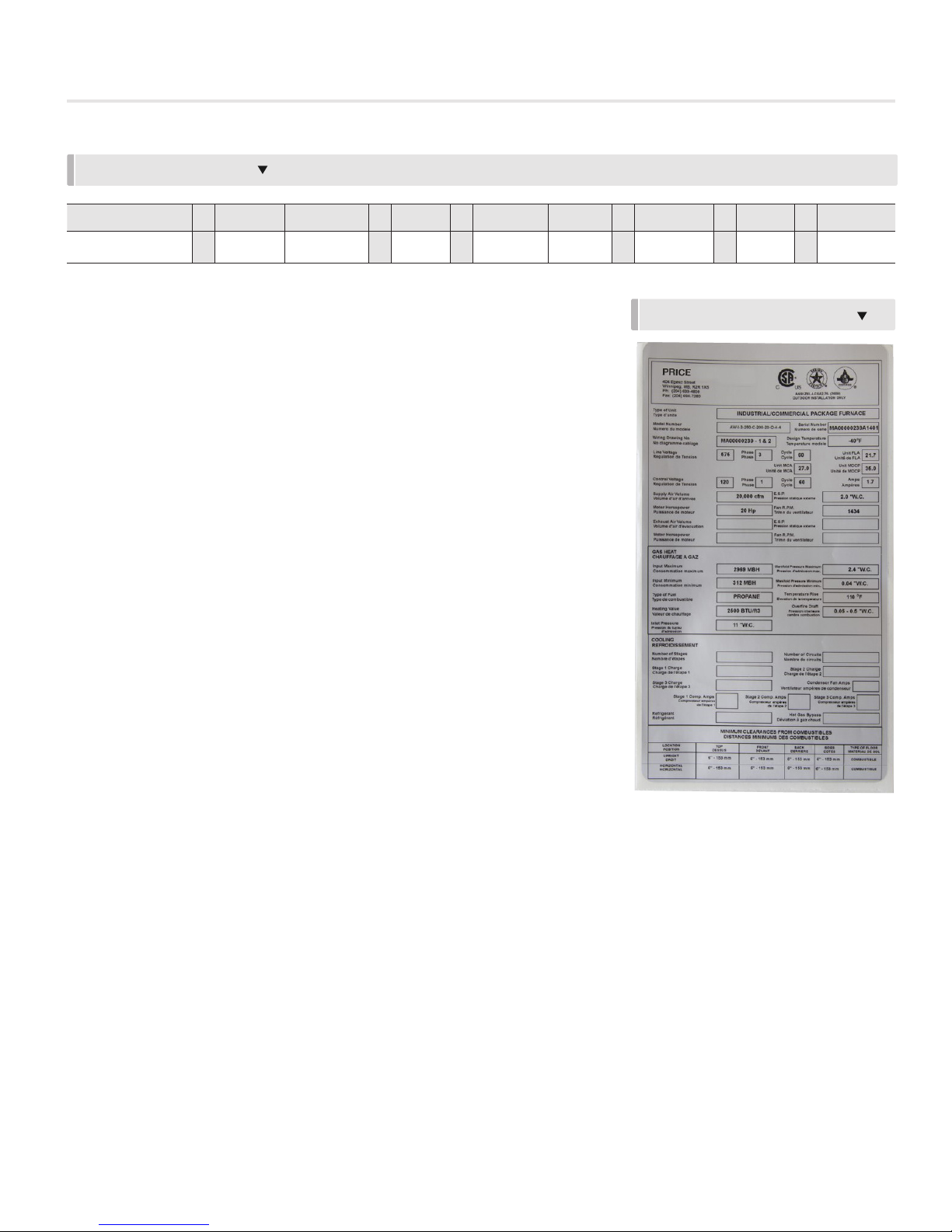
Unit Nameplate
Figure 1 shows a typical nameplate for
an AW-I unit. The nameplate is generally
located in the gas train weather housing.
The nameplate includes model number,
serial number, electrical characteristics
and other pertinent data.
Unit Inspection
This unit has been inspected and test
fired prior to shipment to make sure
the unit is free from defects from the
manufacturer. It is possible that damage
may occur during shipping, rigging and
installation.
Upon receiving the unit, check that
all items have been delivered by
comparing the Bill of Lading to the
equipment received. If anything is
missing or damaged, notify the carrier
immediately. The carrier should note
this on the packing slip or other form
of documentation and provide a
copy. Note: it is a good idea to take a
photograph of any possible damage for
record purposes.
Check the unit model number, heater
size and electrical characteristics to
make sure they are correct. If there
are any issues, do not proceed with
the installation. Contact your sales
representative.
Storage
If the unit is to be stored, take
precautions to prevent condensate
from forming inside the unit’s electrical
compartments. Make sure the
equipment is protected from weather and
dust from site conditions by temporarily
FIGURE 1: TYPICAL NAMEPLATE
sealing all openings to the air tunnel for
outdoor units and completely covering
indoor units.
Do not use the unit for temporary heat
without first completing the start-up
procedure. Price Industries will not
assume any responsibility for equipment
damage resulting from condensate
accumulation on the unit’s electrical and /
or mechanical components.
2
AW-I - Manual | priceindustries.com

ACCESS SIDE
30” (75 cm)
FLUE
9” (22 cm)
FLUE LOCATION
NO ACCESS SIDES
6” (15 cm) minimum
24” (60 cm) recommended
CONTROL CABINET
36” (1 m) minimum
48” (1.3 m) recommended
TOP
6” (15 cm) minimum
NO ACCESS BACK
20” (50 cm) minimum
24” (60 cm) recommended
ACCESS SIDE
30” (75 cm)
FLUE LOCATION
NO ACCESS SIDES
6” (15 cm) minimum
24” (60 cm) recommended
CONTROL CABINET
36” (1 m) minimum
48” (1.3 m) recommended
NO ACCESS BACK
20” (50 cm) minimum
24” (60 cm) recommended
ACCESS SIDE
30” (75 cm)
FLUE
9” (22 cm)
FLUE LOCATION
NO ACCESS SIDES
6” (15 cm) minimum
24” (60 cm) recommended
CONTROL CABINET
36” (1 m) minimum
48” (1.3 m) recommended
TOP
6” (15 cm) minimum
NO ACCESS BACK
20” (50 cm) minimum
24” (60 cm) recommended
ACCESS SIDE
30” (75 cm)
NO ACCESS SIDES
6” (15 cm) minimum
24” (60 cm) recommended
CONTROL CABINET
36” (1 m) minimum
48” (1.3 m) recommended
FLUE LOCATION
AW-I
INSTALLATION INSTRUCTIONS
Mechanical Installation
Location
Price AW-I units are approved for both indoor and outdoor
installations. The installation must conform with local building
codes or in absence of local codes, with the Natural Gas and
Propane Installation Code, CAN/CSA-B149.1, or with the
National Fuel Gas Code, ANSI Z223.1/NFPA 54.
The unit is suitable for use in aircraft hangars, parking
structures and repair garages when marked and installed, as
applicable, in accordance with:
Standard for Airport Hangars, ANSI/NFPA 409
Standard for Parking Structures, ANSI/NFPA 88A
Standard for Repair Garages, ANSI/NFPA 88B
Natural Gas and Propane Installation Code, CAN/CSA-B149.1
No alterations are to be made on this unit.
Unit Clearances
WARNING
COMBUSTIBLE PRODUCTS: The unit must not be operated
in the presence of hazardous atmospheres containing
flammable vapors or combustible dust for risk of fire or
explosion. The use and storage of any flammable material
in the vicinity of the appliance is hazardous.
CORROSIVE PRODUCTS: The unit must not be operated
in the presence of chlorinated vapors, halogenated
hydrocarbons, cleaning solvents, refrigerants, swimming
pool exhaust or in application with airborne substances
containing silicone. When such vapor mixes with the
products of combustion, highly corrosive compounds
result causing premature failure of the heat exchanger and
other components. In such event, the warranty is void.
Exposure to these compounds can lead to personal injury
or death.
Before placing the unit, clearances to combustible materials
and obstructions should be considered.
FIGURE 2: TYPICAL UNIT CLEARANCES FOR AW-I-3 UNITS
FIGURE 3: TYPICAL UNIT CLEARANCES FOR AW-I-4 UNITS
Maintain minimum clearances to combustible materials as
indicated as shown in Figure 2 and 3.
For ease of service, it is also advisable to maintain a minimum
of 48" (1.2 m) clearance to the control side of the unit and 24"
(60 cm) or more on the side opposite of the controls.
If the unit is to be operated within a confined space or within a
building of tight construction, air for combustion and ventilation
must be obtained from outdoors or other spaces freely
communicating with the outdoors.
priceindustries.com | AW-I - Manual
3

AW-I
INSTALLATION INSTRUCTIONS
Roof Curb or Base
Price AW-I units can be installed on a concrete housekeeping
pad, sleepers or a roof curb. The entire perimeter base and
frame structure must be continuously supported with either
field supplied sleepers or structural steel. Make sure that the
sleepers or structural steel supports are the correct dimensions
for the unit and that it is flat and level.
NOTICE - CONTINUOUS STRUCTURAL SUPPORT REQUIREMENT:
The unit is designed to have continuous structural
support around its entire perimeter. Failure to provide
continuous structural support will damage the unit and
void the warranty.
Check that the housekeeping pad is the correct dimensions for
the unit and that it is flat and level. Check that there is enough
trapping height and that a floor drain is nearby where the
furnace condensate drain will be located.
Generally the curb is shipped in advance of the unit delivery.
It should be installed along with any required ductwork prior
to unit installation. Where a roof curb has been supplied
in knocked-down condition, absolute care must be taken
to make sure that all corners are square, and that finished
dimensions exactly match those provided on the drawings. If
this is not done, problems could arise with the seal of the unit
to the curb.
CURB INSTALLATION DETAIL
NOTE: To minimize sound transmission, only cut openings in
roof deck for ductwork penetrations. Do not cut out the entire
roof deck within in the curb perimeter.
If the unit is elevated, a field constructed cat walk around the
unit is strongly recommended to provide access for service.
Check diagonal dimensions prior to securing the curb to
ensure that dimensional integrity has been maintained during
shipping. Shim the curb to the deck as required and complete
roofing in accordance with accepted roofing practices.
Prior to the installation of the unit, check that the curb is the
correct dimensions for the unit and that the curb profile is
correct (this is especially important if the curb is not supplied
by Price Industries). Check that the curb is both level and
square. Curb ductwork that passes down through the
curb must be installed by installing contractor prior to unit
placement. Gasketing or other forms of sealant must be used
around the curb perimeter and at the duct connections. When
the curb is supplied by Price Industries, a neoprene gasket is
included. Prior to the installation of the unit, secure the gasket
to the mating surface of the curb by peeling the backing off the
gasket material and applying adhesive-side down.
4
AW-I - Manual | priceindustries.com
AW-I
INSTALLATION INSTRUCTIONS
Unit Assembly
CAUTION
HEAVY COMPONENTS: The unit sections are very heavy
and significant force will need to be applied to cinch the
sections together. Make sure everyone is clear of the
sections prior to cinching to avoid injury.
SLIP UNITS: Price AW-I units may be shipped as a single
unit or in sections for field assembly by the installing
contractor. For proper assembly of split units, refer
to Appendix A of this manual. Failure to follow the
instructions in this manual may void your warranty.
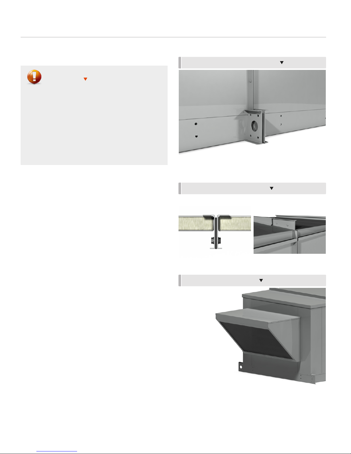
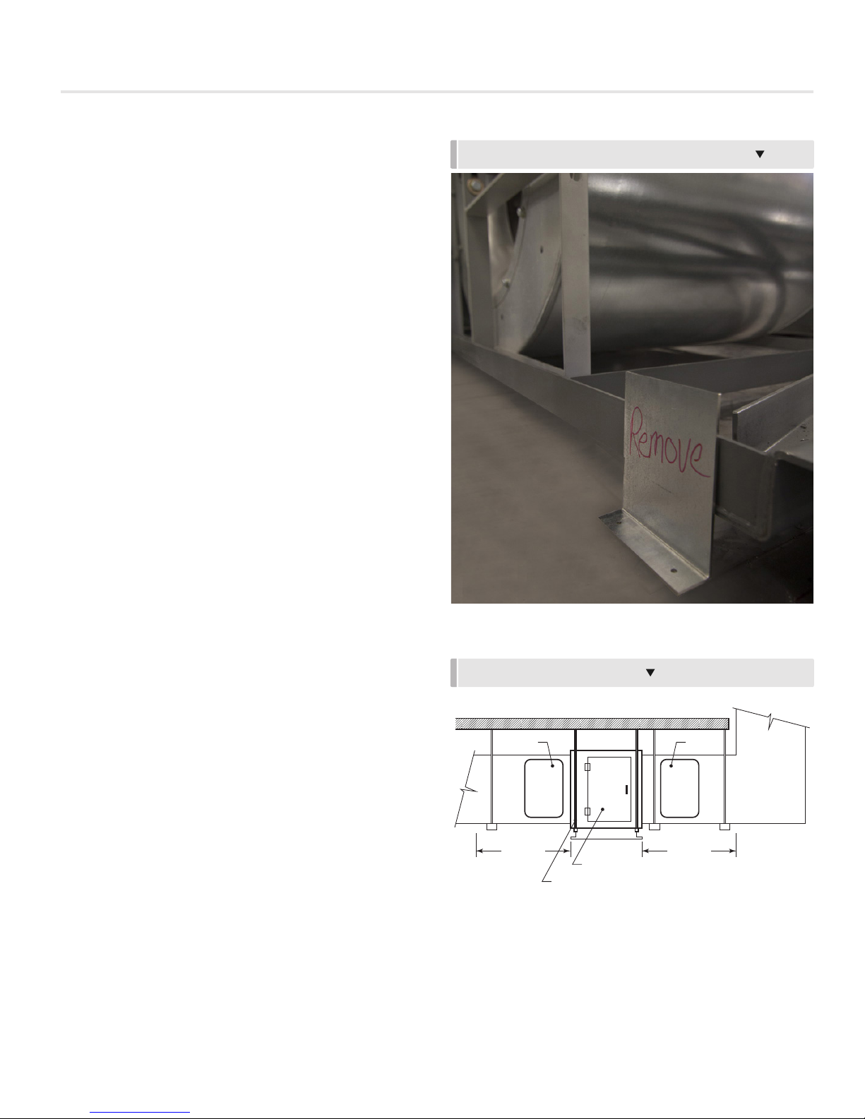
Figure 4: Split unit sections shall only be pulled together using
the provisions on the base. Trying to pull sections together
from the cabinet walls or roof will damage the cabinet and void
the warranty. Refer to Appendix A.
Figure 5: Where sections join together, a flanged joining strip
with bolt holes is provided. Refer to Appendix A for detailed
instructions on how to attach these strips and all other
components needed to properly seal between the unit splits.
FIGURE 4: TYPICAL BASE CINCH POINTS
FIGURE 5: TYPICAL FLANGE JOINTS
Figure 6: Mount any loose items such as intake hoods and
secure them to the unit with self-tapping fasteners.
Figure 7 (on the next page): Remove all shipping braces, packing
etc. from the unit.
FIGURE 6: OUTDOOR AIR HOOD
priceindustries.com | AW-I - Manual
5
AW-I
INSTALLATION INSTRUCTIONS
Duct Connections
On outdoor units with ducting passing down through the
curb, the ducting will be installed prior to unit placement and
attached to the curb. For all other duct connections, the
ductwork will be connected to the unit casing using sheet
metal screws by the installing contractor. Unless indicated on
the submittal drawings, the weight of the ducting should not
be placed directly on the unit. The installing contractor should
provide an external means to carry the duct weight.
Access panels in the ducting near the unit are recommended.
Where no access to the unit inlet or discharge section is
provided as part of the unit (for example an access door in the
unit), access panels are strongly recommended for inspection
and service.
Duct Furnace Installation
Where AW-I furnaces are supplied as duct furnaces, the
following installation requirements apply:
1. Duct furnaces shall be installed on the positive pressure
side of the fan.
2. Duct furnaces shall be installed with an inlet duct which will
provide air distribution equivalent to a straight run of duct
having the same cross-sectional area as the inlet connection
and no less than two equivalent diameters in length.
FIGURE 7: TYPICAL FAN BASE SHIPPING BRACKET
3. Provide removable access panels on both upstream and
downstream sides of the duct furnace. These openings
shall be accessible when the appliance is in service, and
shall be of such a size that smoke or light may observed
inside the casing to indicate the presence of leaks in the
heating element. The access panels shall be attached in
such a manner as to prevent leaks.
4. High static packaged heaters must be adjusted to obtain
temperature rise, manifold pressure and air flow within
the range specified on the unit rating plate. Duct furnaces
must be adjusted to obtain an air flow rate within the
range specified on the appliance rating plate.
5. For altitudes of 2000 – 4500 feet (600 and 1350 m),
derate the maximum rated input by 10%.
6. The appliance shall not be installed downstream from
evaporative coolers, air washers or cooling units of
refrigerating systems unless the following optional
conditions are met.
a) if the heating element is made of corrosion resistant
material as per ANSI 83.8/CSA 2.6 clause 4.29.1 , it
can be installed downstream for evaporative coolers or
air washers.
DUCT FURNACE INSTALLATION
ACCESS
PANEL
2 diameters
DUCT FURNACE
HANG UNIT WITH ROD
CONNECTED TO BASE
ACCESS
PANEL
2 diameters
b) if the appliance complies with all of the optional provisions
outlined in ANSI 83.8/CSA 2.6 clause 4.29 and 5.30
the appliance may also be installed downstream from
refrigerated units supplying air below the dew point of the
ambient air surrounding the appliance.
6
AW-I - Manual | priceindustries.com

AW-I
INSTALLATION INSTRUCTIONS
Vent Stack and Combustion Air Opening
Outdoor Installation
AW-I units are certified as Category III appliances with positive
vent pressure and stack temperature not exceeding 500°F
(260 °C). Outdoor AW-I units are equipped with a factory
mounted exhaust stack. This stack is made especially for the
unit and should not be removed or altered in any way.
The gas train and burner vestibule is equipped with ventilation
and combustion air openings. The appliance must be installed
so that these openings are unobstructed. The unit must be
installed in a location with adequate clearances to provide
sufficient combustion air space, service, inspection and
clearance from combustible material as marked on rating plate
or as per local codes and authorities having jurisdiction.
Indoor Installation
WARNING
POISONOUS GASES: The products of combustion from any
gas appliance contain poisonous gases including Carbon
Monoxide. Failure to properly install the chimney for an
indoor installation could lead to dangerous gases being
released within the building that in turn lead to death or
serious injury. Follow the installation instructions carefully.
OUTDOOR EXHAUST STACK
NOTICE - CONDENSATE: Some chimney installations will
cause condensate to form in the chimney. Failure to
properly drain the condensate from the chimney could
lead to damage in both the chimney and the unit. This will
void the warranty.
Vent installation shall conform with local codes or, in the absence
of local codes, with the National Fuel Gas Code, ANSI Z223.1/
NFPA 54, or the National Gas and Propane Installation Guide,
B149.1.
The unit must be installed in a location with adequate clearances
to provide sufficient combustion air space, service, inspection
and clearance from combustible material as marked on rating
plate or as per local codes and authorities having jurisdiction.
The appliance shall be located in such a manner that it does not
interfere with the circulation of the air in the space being served.
Outdoor air must be introduced in accordance with National
Fuel Gas Code, ANSI Z223.1/NFPA 54, or the National Gas and
Propane Installation Guide, B149.1.
Install air openings that provide a total free area in accordance
with the following;
1. Air from inside the building – Opening of 1 square inch per
1000 Btu/h ( 22 cm² per kW) input but not less than 100
square inches (650 cm).
2. Air from outside ducted – Opening of 1 square inch per
2000 Btu/h ( 11 cm² per kW) input.
3. Air from outside, direct opening - Opening of 1 square
inch per 4000 Btu/h ( 6 cm² per kW) input.
The combustion products must be vented to the outdoors.
All venting installation shall conform with local codes or, in the
absence of local codes, the National Fuel Gas Code, ANSI
Z223.1/NFPA 54, or the National Gas and Propane Installation
Guide, B149.1. Indoor AW-I units are supplied with a round
flue connection as shown on the unit drawing. AW-I units are
certified as Category III appliances, with positive vent pressure
and stack temperature not exceeding 500°F (260 °C). Care
must be taken to avoid flue products from entering the space.
Only use vent material and components that are UL listed and
approved for Category III appliances.
priceindustries.com | AW-I - Manual
7
AW-I
INSTALLATION INSTRUCTIONS
Before starting installation, examine all components for
possible shipping damage.
1. Venting shall be installed in accordance with the appliance
manufacturer's instructions. Venting shall conform with
local codes or the National Fuel Gas Code, ANSI Z223.1/
NFPA S4, or the Natural Gas and Propane Installation
Code, CSA B149.1.
2. AW-I units are approved with type “A” vents.
3. Each unit must have its own individual vent pipe and
terminal. Do not common vent or connect more than one
appliance to the venting system.
4. All vent pipe joints must be sealed to prevent leakage.
The joints must be screwed with a minimum of five #10
stainless steel screws. Use approved high temperature
sealant to seal the joints.
5. The total equivalent length of vent pipe must not exceed
50 feet (15.25 m). Avoid unnecessary turns and any other
features that create resistance to the flow of flue gases.
6. Maintain the same vent diameter all the way to the end.
7. The vent shall be extended high enough above either
a building or the neighboring obstructions so that wind
from any direction will not create a positive pressure in the
vicinity of the vent termination. The vent shall extend at
least 18” (450mm) above the highest point where it passes
through the roof surface and any other obstruction within
a horizontal distance of 18” (450mm).
14. The vent shall terminate in accordance with the National
Fuel Gas Code, ANSI Z223.1/NFPA S4, or The Natural
Gas and Propane Installation Code, CSA B149.1. Provide
minimum vent termination clearances to the building as
shown below:
Structure Min. Clearances
Public paved driveway 7’ above (2.1m)
Grade/snow level 1’ (300mm)
Mechanical air supply inlet 6’ (1.8m)
Window, door or any other opening 3’ (900mm)
Meter/regulator
15. All horizontal runs shall include ¼” per ft (21 mm per m)
pitch and a maximum horizontal length of 10 ft. (3 m)
without a power vent.
16. Do not connect into any portion of mechanical draft system
operating under positive pressure.
3’ (900mm) horizontally
15’ (4.5m) vertically
TYPICAL CHIMNEY INSTALLATION
8. The venting system shall be firmly attached to flue collar
with stainless steel screws.
9. The venting system shall be securely supported by
noncombustible hangers suitable for the weight at a
minimum of 36” (1m).
10. When a vent penetrates a floor or ceiling and is not
running through the fire rated shaft, a fire stop and support
is required.
11. The vent system must be installed to prevent collection of
condensate. Use a condensation drain if necessary. The
heat exchangers are equipped with condensate drain(s)
and all the condensation must be disposed in accordance
with local codes.
12. Maintain a minimum of 9” (22 cm) clearance between the
vent pipe and combustible material. Insulate the pipe run
longer than 10’ (3m) for pipe routed through unheated
area with a minimum of ½” (12.5mm) thick foil face
fiberglass, 1 ½ lb. (680,4 g). density insulation.
13. Venting system must be accessible for inspection.
NOTE: Do not intermix vent parts from different manufacturers in
the same vent system.
8
AW-I - Manual | priceindustries.com
AW-I
INSTALLATION INSTRUCTIONS
Electrical Installation
WARNING
ELECTRICAL SHOCK HAZARD: Disconnect all electric power,
including remote disconnects before servicing. Follow
proper lockout/tagout procedures to ensure the power
cannot be inadvertently energized. Failure to disconnect
power before servicing could result in death or serious
injury.
NOTICE - USE COPPER CONDUCTORS ONLY: Unit terminals
are designed for copper conductors only. Failure to use
copper conductors may result in unit damage.
Main Power Connection
All connections to the unit and the main disconnect switch
must conform to the Canadian Electrical Code/National
Electrical Code and local codes.
1. Before proceeding with electrical connections, ensure that
the unit characteristics and the intended supply match.
The proper voltage for connection is listed on the rating
plate attached to the unit.
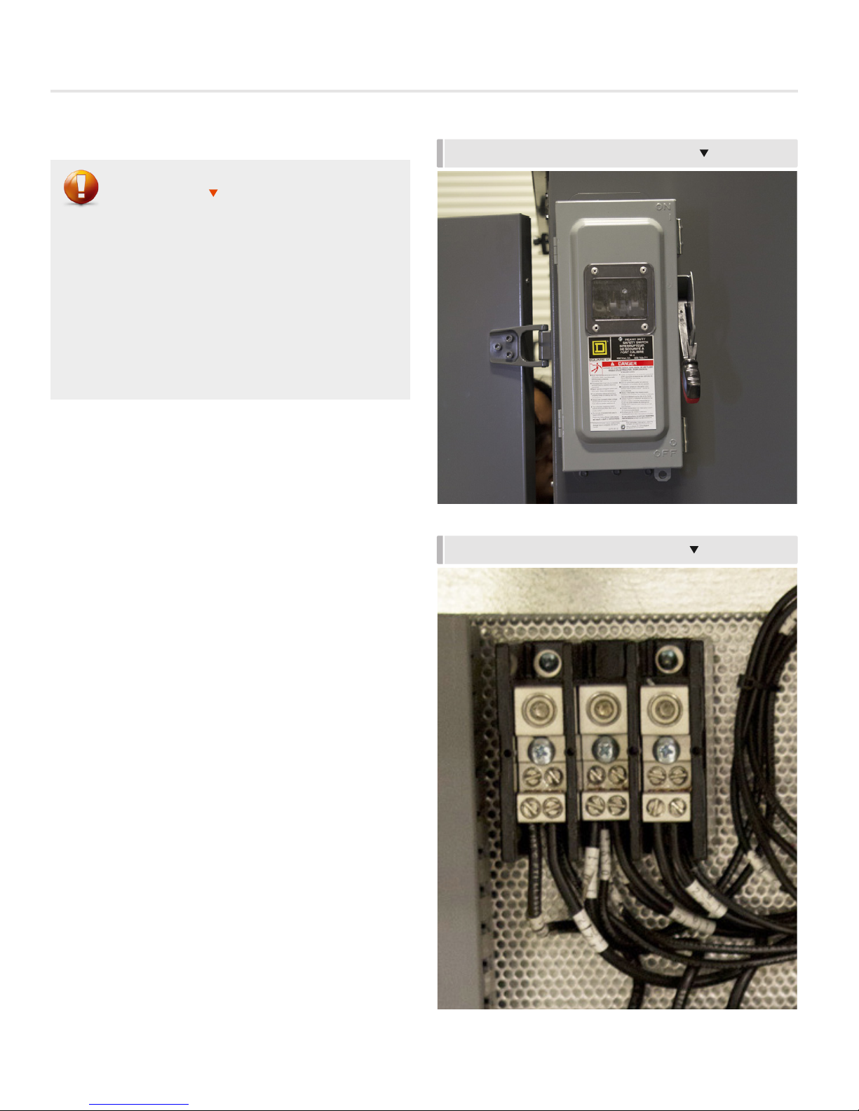
TYPICAL FACTORY SUPPLIED DISCONNECT
TYPICAL SPLITTER BLOCK TERMINATION
2. Unit must be electrically grounded in accordance with local
codes, or in the absence of local codes, with the National
Electrical Code, ANSI/NFPA 70, and /or the Canadian
Electrical Code, CSA C22.1, if an external electrical source
is utilized.
3. Refer to the unit submittal drawing to determine the
suggested location of the field wired power supply. Where
a disconnect is supplied as part of the unit, the main
power connection will be the line side of the disconnect.
4. If the unit is not supplied with a factory mounted
disconnect, a field supplied disconnect must be installed
in accordance with local codes, or in the absence of local
codes, with the National Electrical Code, ANSI/NFPA
70, and /or the Canadian Electrical Code, CSA C22.1.
Where a disconnect is supplied by others, the main power
connection to the unit will be the line side of the main
splitter block. Refer to unit electrical wiring diagrams for
details.
5. Ensure that the routing of the power supply wiring does
not interfere with removal of any unit access door, or in any
way hinder servicing of the unit.
priceindustries.com | AW-I - Manual
9

AW-I
INSTALLATION INSTRUCTIONS
6. Refer to the submittals for electrical service routing.
Unless indicated on the submittals, DO NOT penetrate
the floor of the unit to route electrical conduits to the unit
control panel. Provide a pitch pocket in accordance with
standard roofing practice.
7. For units that are shipped in multiple sections, some
electrical connections may have to be made by the
installer in the field. Field wiring to be done by the installer
appears as a dotted line on the wiring diagram. Wiring
to connect two sections of a unit will be marked by the
factory and a terminal block will be provided for such
connections.
8. Fuses are furnished and installed by the factory in
accordance with the National Electrical Code, ANSI/NFPA
70, and /or the Canadian Electrical Code, CSA C22.1.
Should the replacement of any fusing become necessary,
the replacement MUST be of the same amperage as
the original. Failure to use equivalent replacement fuses
may result in damage to components within the electrical
system of the unit and/or the building. If any of the original
wires need to be replaced, they must be replaced with
type TEW 105° or equivalent except where noted.
9. On units with three-phase power supplies, make sure that
motor rotation is correct as connected.
ELECTRICAL INSTALLATION W/PITCH POCKET
CONVENIENCE OUTLET AND LIGHTS
Auxiliary Power Connections
A separate 120/1/60 power supply may be required on
units with convenience outlets and lights. Refer to unit wiring
diagrams for wiring sizing details and connection points.
Controls Installation
All field wiring must be in accordance with local codes, or in
the absence of local codes, with the National Electrical Code,
ANSI/NFPA 70, and /or the Canadian Electrical Code, CSA
C22.1.
Field controls wiring requirements will depend on the controls
provided with the unit. A basic unit will require controls by
others. Only the minimum safety controls are provided by
Price Industries. A controller or thermostat must be provided
by the installing contractor. Refer to unit electrical wiring
diagrams for details.
Units supplied with controls may require field wiring to a
remote sensor or control panel. Refer to unit electrical wiring
diagrams for details.
10
AW-I - Manual | priceindustries.com
 Loading...