

PRIAM DISKOS 3450, DISKOS 7050 Service Manual
OEM/SERVICE MANUAL
DISKOS 3450
DISKOS 7050
EIGHT INCH
WINCHESTER
DISC DRIVES

IPIRllAM
a-Inch
Winchester
OEM/Service
Disc
Drives
Manual
JULY
1982

IPRllAM
a-Inch
Winchester
OEM/Service
Changestothis
This manual
it
current
Changes
that
alert field service
lem areas and changes in maintenance procedures.
After
a seriesofthese notes are issuedora critical one is issued, we
which
type. A vertical bar in the marginofthe changed
page
20%
reissue the entire manual. When PRIAM prepares
a change package,itsends
users. The change packages are available upon
request and
Reader
If you are
wanttohear from you. Tell us
formation,
mation. If you
please let us know
cific
the paragraph number,ifpossible.
are the remove-the-old and insert-the-new
indicates
of
the
Comments
and give the page number, line reference, and
Manual
will
be changed
with
improvements as we make them.
start
with
Field Engineering
technicianstocritical
will
the revised material.
manual's
without
dissatisfied
typographical
know
pages are changed, we
charge.
a waytoimprove a procedure,
about
periodicallytokeep
publish
with
errors,ormissing
that, too. Please be spe-
changed pages,
announcementstoits
this
publication,
about
inaccurate
Bulletins
After
prob-
about
will
we
in-
infor-
Disc
Drives
Manual
Safety Precautions
As
with
any
electronic
consistent
tices
ment
voltages. Any servicing
cabinet
service personnel. Always
to
inspectionorservicing.
Admonishments
manual
situations
damage,orpersonal injury.
A WARNING
cedures that,ifnot
in injurytothe service technician. A CAUTION statement
strictly
structionofequipment
NOTE
maintenance
facts. NOTEs also provide information that, though
not
necessary, is helpfultothe understandingofa
conceptorthe
with
all standard
must
be observed
since
precedes the
statement
it
contains
covers should be performed by
are included
to
alert the readertoproblem areas
that
could
statement
observed, could result in damageorde-
highlights
procedures,
completionofa procedure.
equipment,
industrial
while
servicing
potentially
that
requires removing
disconnect
cause lossofdata, hardware
precedes the
strictly
textofa procedure that,ifnot
observed, could result
(hardwareorsoftware). A
essential operating
conditions,orclarifying
precautions
safety
this
dangerous
qualified
power prior
throughout
textofpro-
prac-
equip-
this
or
or
Change
A vertical line in the
cates the
Shaded areas
and diagrams.
The total number ofpagesinthis document is 69.
Page No. Change Number*
Dates of issue for original and changes pages are: *0inthis
column indicates an original page.
Notation
portion
indicate
of
outer
marginofa page indi-
text
affected
changes
to
Page No. Change No.*
by changes.
illustrations
The
following
are not related
thereforedonot
Personnel
phasesofinstallation
KEEPAWAY FROM LIVE CIRCUITS.
Observe
all the CAUTIONS and WARNINGS in
when
working
DO
NOT SERVICEORADJUST ALONE.
Never reach
ment unless someone capable
present.
must
safety
into
are general
to
appear elsewhere in
heed these
WARNING
precautions
with
the equipment.
the
safety
any
specific
warnings
and maintenance.
at all times. Observe
cabinettoservice the equip-
precautions
procedure and
of
that
this
manual.
during many
this
manual
giving aid is

The
following
inside the
where in the
here
for
emphasis:
Voltage hazardoustohuman
the cabinet. Use extreme
WARNING appliestoany service
equipment
textofthis
cabinet.
manual and is introduced
WARNING
caution
It
appears else-
life
are exposed in
when servicing
either
terminals
Warranty
For warranty
the power
are exposed.
supplyorany area where power
information,
contact
PRIAM:
(408) 946-4600.
TABLE
Section
1.
GENERAL INFORMATION .
1.1
1.2
2.
INSTALLATION .
2.0
2.1
2.2 Shipping Damage
Overview .
Options
Introduction
Unpacking and Receiving
Inspection .
Inspection
Page
.
.
.
2.3 System Unpacking .
2.4 Inspection Procedures .
2.5 Reshipping Procedures .
2.6
Switch
Settings
.
2.7 Cabling .
2.8
Unlocking
.
2.9 Locking .
2.10 Repacking .
2.11 Storage .
2.12
Shipping
.
2.13 Spindle and Head Locks .
2.14 Powering Up/Down .
2.15 Performance Check .
3.
FUNCTIONAL DESCRIPTION. . . . . . . . . . . 9
3.1 Overview. . . . . . . . . . . . . . . . . . . . . . 9
3.2 Servo
3.3 Servo Pattern. . . . . . . . . . . . . . . .
3.4 Data
3.5
3.6 Defect
3.7 Data
3.8 Overview. . . . . . . . . . . . . . . . . . . .
3.9
3.10
3.11
Surface.
Surface..................
Track
Drive
Power Up/Down Sequences 12
Motor
Format..................
Location
Sector
Selection................
Control
. . . . . . . . . . . . . . . . . 9
Record
Format.
Circuitry.
Format..
. . . . . . . . . ...11
. . . . . . .
..
10
11
11
..
12
12
..
12
OF
CONTENTS
1
1
1
3
3
3
3
3
3
3
3
3
4
4
5
5
5
5
7
7
9
Section
3.12
3.13
3.14
3.15
3.16
3.17
3.18
3.19
3.20
3.20.1
3.20.2
3.20.3
3.20.4
3.20.5
3.20.6
3.20.7
3.20.8
4.
TROUBLESHOOTING
4.0
4.1
4.2 General
4.3
4.4
4.5
4.6
4.7 Head Disc
4.8 Servo and
Seek Modes 12
Servo
Data Read/Write
PLO/VFO 17
Microprocessor
PRIAM
Connectors
Interface Signal
SMD Interface
Overview. . . . . . . . . . . . . . . . . . . .
Connectors
Interface Signal
Interface
Interface
Format Design
Write Format Procedure
Control
Introduction.
Field
Maintenance
Status
Symptoms
Seek Errors and Fault
Precautions.
Circuitry.
Interface...............
DC
Timing
Adjustments
Inspection
and Error Codes
. . . . . . . . . . . . . .
Functions.
Flow
and Pin
and Pin
Characteristics
Timing
. . . . . . . . . . . . . . . .
and Causes
. . . . . . . . . . . . . . . .
Assembly
Motor
Assignments.
Descriptions..
Assignments.
Descriptions..".
and Preventive
Control PCB..".
4.9 Read/Write Digital PCB
4.10 Power Supply
Spare Parts
Schematics.
List
. . . . . . . . . . . . . . . .
. . .
Charts.
Conditions.
. .
..
..
..
..
".
..
".
".
".
".
".
".
..
".
".
".
".
...
".
".
".
".
..
Page
14
14
18
18
18
35
45
45
45
46
50
52
54
54
55
57'
57
57'
57
57
57
62
63;
63
63
63
63
64
65
ii
LIST
OF
FIGURES
Figur~
2-1.
2-2.
2-3.
Read/Write Digital
Servo and
Daisy-Chaining an 8-inch Drive
PRIAM Interface
2-4.
3-1.
3-2.
3-3.
LocationofHead and Spindle
Servo and Data Surfaces
Servo Track Signals
Simplified Block Diagramofa PRIAM Receivers
8-inch Disc Drive
3-4.
3-5.
3-6.
3-7.
3-8.
3-9.
3-10.
3-11.
3-12.
3-13.
3-14.
3-15.
3-16.
3-17.
3-18.
3-19.
3-20.
3-21.
3-22.
3-23.
3-24.
Motor
Servo Circuitry
Read/Write Timing and Encoding
Data Read and Write Circuitry
Initialization Flow Chart
First Idle Flow Chart
Idle Flow Chart
Command Decode Flow Chart
Sequence Up Flow Chart#1........
SequenceUpFlow Chart#2........
Sequence Down Flow Chart
Restore Flow Chart
Seek Flow Chart
Restore Subroutines Flow Chart
Seek Subroutines Flow Chart#1....
Seek Error Flow Chart.
Last Track Flow Chart#1..........
Last Track Flow Chart#2..........
Seek Done Flow Chart.
Fault Reset Flow Chart
Read Drive ID and
Read Bytes/Sectors Flow Chart
3-25.
Seek Start Flow Chart.
Motor
Controller
...................
...................
PCB
...........
Control PCB
.................
..........
...............
.................
.................
......'.....
..............
........
...............
.................
............
............
............
............
......
with
Lock.
...
......
......
....
.....
Page
4
4
5
6
9
10
13
14
15
16
17
19
20
21
22
23
24
25
25
25
26
27
28
29
30
31
32
32
33
Figure
3-26.
3-27.
3-28.
3-29.
3-30.
3-31.
3-32.
3-33.
3-34.
3-35.
3-36.
3-37.
3-38.
3-39.
3-40.
3-41.
3-42.
3-43.
3-44.
3-45.
3-46.
3-47.
3-48.
3-49.
3-50.
3-51.
Calibrate Flow Chart.
DBUS Transceiver
.............
................
Single End Line Receiver Gated By
DRIVE SELECT
Single End Line Receiver
Single End Line Driver
..................
..........
.............
Differential Line Drivers and
.......................
Register Load Timing
Register Read Timing
Reset
Timing
....................
.............
.............
INDEX and SECTOR MARK Timing
WRITE DATA and
WRITE CLOCK Timing
............
READ DATA and
READ CLOCK Timing
Record Writing Timing
Record Reading Timing
.............
............
...........
Read and Write Transitions
During Gap
Typical Read/Write Data and
Transmitter and Receiver
Control Line Transmitter
Control Line Receiver
Tag and Bus Timing
Typical Read Timing
Typical Read Control Timing
Typical Write Control Timing
Index and Sector Mark
Drive Select Timing
NRZ Data and Read
Recommended Sector Format
......................
...........
.............
...............
..............
............
...............
Clock
Clock
..........
.......
.......
Timing
......
...
..
Page
34
38
38
38
39
39
40
40
40
40
40
41
41
42
42
50
51
51
52
53
53
53
53
53
54
55
iii
LIST
OF
TABLES
Table
1-1.
2.4.
3-1.
3-2.
3-3.
3-4.
3-5.
3-6.
3-7.
3-8.
3-9.
Table Page
3-10.
3-11.
3-12.
3-13.
Specifications
Disc Drives
S~itch
Settings
Digital PCB
for
.......................
.......................
Head Selection
DBUS Transceiver
Characteristics
PRIAM 8-inch
on the Read/Write
...................
DC
...................
Page
2
3
37
38 AC
Single End Line Receiver Gated by 3-14.
DRIVE SELECTED
Single End Line Receiver
Characteristics
Single End Driver
Characteristics
Differential Receiver
Characteristics
Differential Line Driver
Characteristics
Register Load AC
Register Read AC
Characteristics
DC
...................
DC
...................
DC
...................
DC
...................
Characteristics
Characteristics
....
...
...
38
38
39
39
39
39
40
3-15.
3-16.
3-17.
3-18.
3-19.
3-20.
3-21.
3-22. Tag Bus Decode
3-23.
Reset AC
Characteristics
...........
INDEX and SECTOR MARKAC
Characteristics
.................
WRITE DATA and WRITE CLOCK
AC
Characteristics
................
READ DATA and READ CLOCK
Characteristics
Record
Writing
Characteristics
................
Control AC
...................
Record Reading Control AC
Characteristics
Register Selection
Command Code Summary
Drive ID
Status
Assignments
Register
Address Register
Tag Bus I/O Interface
"B"
Cable Interface
...................
.................
..........
..............
Bit
Definitions
Bit
Definitions
("A"
Cable)
("A"
Cable)
................
........
......
.....
....
40
".
40
40
41
41
42
43
43
44
44
45
46
47
47
iv

1.
GENERAL INFORMATION
1.1
ogiestoprovide users
having high capacity, fast access, and long-term
reliability. Linear
track
and 7050
quickly
sure high
The DISKOS 3450 and 7050 use advanced
Winchester
following
to
and precisely. These low-force heads as-
data
and
microprocessor
with
low-cost
motor
servos enable the DISKOS 3450
position
reliability.
voice
coil
Winchester
positioners
technol-
disc
drives
type heads
with
The Servo and
the
circuitry
from the servo read head, and
positionofthe head carriage.
The Read/Write Digital PCB
cuitry
mand execution, and
the user interface.
1.2
associated
Options
used
Motor
control
for
processing the servo
with
read/write
information
PCB also
for
controlling
contains
all the cir-
control,
transfers across
contains
signals
the
com-
Advanced 8-inch Winchester-technology
driven by an outer-rotor, brushless
head
discs
resistant
One head serves each
face is
servoed
write
per inch are used in the DISKOS 3450toprovide a
capacity
DISKOS 7050, the three
tracks
(unformatted)ofdata.
Microprocessors
tronicstoprovide interface
tor
power up and
program
power-up sequence. Any
these
the chanceoflossofdataordamagetothe drive.
PRIAM
fashion, so
easily replaced. This greatly reduces down
duetoservicing. The three
The Head Disc Assembly(HDA) is a sealed enclo-
sure. It
motor, Hall
head carriage assembly,
netic
The Servo and
circuitry
tor. This
from the Read/Write Digital PCB, and
tation
the HDA.
positioner
are enclosed in a sealed,
chambertoassure high reliabilIty.
dedicatedtoservo
track
timing.
of
per
inchtoaccommodate
drive operation. For example, they
checks
tests
disc
Head Disc
Servo and
Read/Write
contains
discs, and
associated
circuitry
feedback from the Hall
coil
and carriage, heads and
contamination-
disc
surface, and a full sur-
information
following,
Three
35
will
drives are
that
Effect
discs
megabytes,
are used in the disc-drive elec-
down
drive performance
prevent drive start-up, reducing
defective
the drive
sensors, voice
air
filter
Motor
receives an
head
recordedat480
discs
sequencing, and a self-test
malfunction
constructed
assemblies
Assembly
Motor
Digital
spindle
read/write
assemblies.
Control PCB
with
driving the
positioning,
unformatted.
are recorded at 960
flexibility
assemblies
control
PCB
assembly, drive
On/Off
Effect
discs
DC
motor. The
for
tracks
In the
70
megabytes
andtomoni-
control
during
detected
in a
modular
can be
are:
PCB
coil
actuator,
heads, mag-
contains
spindle
command
spindle
sensors in
are
fully
and
each
by
time
the
mo-
ro-
1.2.1
interface
can be used,
drive in the 8-inch family. All PRIAM
clude
The standard PRIAM
cost
based systems. Up
chained, when
intEHface provides a basic 8-bit
which
and 16-bit microprocessors. It
serial NRZ data exchange. No elaborate handshaking
built
50-conductor
the PRIAM
The SMD Interface
used
controllers. In the 8-inch drives the SMD
is available as an adapter
tween the drive electronics and the SMD controller.
The line drivers and line receivers in the SMD in-
terface are
trollers. There are
the host
disc
twisted-pair
ductor
The ANSI
interface
Committee
terface
data
and radial
eight
50-conductor
1.2.2 Interface Cables and Terminators. I/O
necting the user's controller
drive, and
one another.
Interface
disc
options.
on-board
and
for
may be used
protocols
into
the
interface
with
existing
matchedtothoseoftypical
system's
drive's SMD Interface - a 60-conductor
flat
ribbon cable
interface
standard proposed by ANSI Technical
X3T9.
include
transfer
attention
drives may be daisy-chained, on a
cables are available from PRIAM,
for
Options. The PRIAM 8-inch
drives are available
Eachofthese
without
data
efficient
this
are required. The PRIAM
disc
flat
flat
cable
variable and fixed
rates upto10
flat
connecting
modification,
separation.
interface
use
to
four
interface
with
the
drive's
ribbon cable is
SMD
Characteristicsofthe ANSI in-
ribbon cable.
read/write
and the
permits
Storage
two
interface cables between
controller
("A"
("B"
complies
and
select
daisy-chained drives
with
interface
is designed
with
microprocessor-
drives may be daisy-
is used. The PRIAM
bidirectional
currently
also
digital
Ulsed
host
system.
a PRIAM drivetobe
Module
whichisinstalled
and the PRIAM
cable) and a 26-con-
cable).
with
the
megabits
capability. Up
to
the PRIAM
a variety
options
on any
interfaces
for
popular
provides bit-
interface
PCB. A
between
Drive (SMD)
interface
SMD con-
disc
sector
per second,
for
disc
in-
low
bus,
8-bit
be-
drive
sizes,
single
con-
disc
to
of
is
to
1
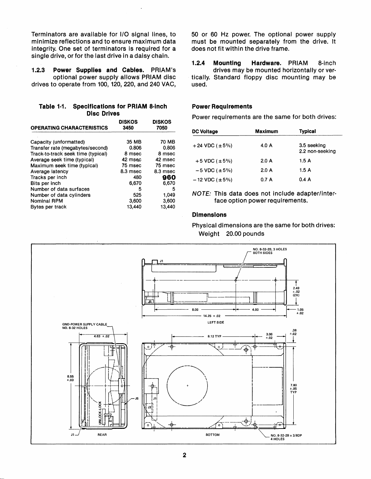
Terminators are available for I/O signal lines, to
minimize reflections and
integrity. One set
of
to
ensure maximum data
terminators is required for a
single drive, or for the last drive in a daisy chain.
1.2.3 Power Supplies and Cables. PRIAM's
optional power supply allows- PRIAM disc
drives to operate from
1·1.
Table
Specifications
100,
120,220, and
for
PRIAM a-inch
240
VAG,
Disc Drives
OPERATING CHARACTERISTICS
Capacity (unformatted)
Transfer rate (megabytes/second)
Track-to-track seek time (typical)
Average seek time (typical)
Maximum seek time (typical)
Average latency
Tracks per inch
Bits per inch
Number
Number
Nominal RPM
Bytes per track
of
data surfaces
of
data cylinders
DISKOS DISKOS
3450
35
MB
0.806
8msec
42
mse.c
75
msec
8.3msec
480
6,670
525
3,600
13,440
5
7050
70
0.806
8 msec
42
msec
75
msec
8.3 msec
960
6,670
1,049
3,600
13,440
MB
50
or
60
Hz
power. The optional power supply
must
does not
be
mounted separately from the drive. It
fit
within the drive frame.
1.2.4 Mounting Hardware. PRIAM a-inch
drives may be mounted horizontally or
vertically. Standard floppy disc mounting may be
used.
Power Requirements
Power requirements are the same for both drives:
DC
Voltage
+24
VDC
(±5%)
+5
VDC
(±5%)
-5
VDC
(±5%)
-12
VDC(±5%)
5
NOTE: This data does not include adapter/inter-
Maximum
4.0 A
2.0
A
2.0
A
0.7
A
Typical
3.5
seeking
2.2
non-seeking
1.5 A
1.5
A
0.4
A
face option power requirements.
Dimensions
GND-POWER SUPPL V CABLE
NO. 8-32 HOLES
8.55
±.03
Physical dimensions are the same for both drives:
Weight 20.00 pounds
--------
-----iL-
______
8.00
.J
-----11+--
14.25
LEFT SIDE
8.12
±.02
TYP
__
-----/-ot-
I
~--l
J
7.80
±.05
TYP
I I
J5
I I
f------
I~f_+---------_r_--_J_---
_____
J1
REAR
~--
BOTTOM
-J-=-~
~
---i+-e-"t+---'-
.....
I
NO. 8-32-2B x 3/8DP
4 HOLES
2

2.
INSTALLATION
2.0
It includes
specting, and procedures
equipment
2.1
Introduction.
cedures
for
instructions
to
the powersource.
This Chapter
installing
for
for
contains
pro-
the 3450 Disk Drive.
unpacking and in-
interconnecting
the
Unpacking and Receiving Inspection. When
the 3450 Disc Drive is delivered by a transfer company,
the shipping
If
the
unitisto
it
must
be carefully inspected (inside
container
as well as out)
be reshipped,itmust
for
damage.
be repacked
in amannerthat will prevent damage while in transit.
2.2 Shipping Damage Inspection. Prior
accepting
from the carrier, carefully inspect
container
note
agent
pany
for obvious damage.Ifdamage is found,
it
on the waybill and require the delivery
to
sign the waybill.
immediately
deliveryofthe 3450 Disc Drive
the shipping
and
Notify
submit
the transfer com-
a damage report
to
to
the carrier.Ifno exterior damage exists, unpack
the system and
inspect
for hidden damage.
2.5 Reshipping Procedures. Should the equipment
be reshipped prepare the
for
shipping
a.
Check the
rity
of
b.
Place the drive
as follows:
integrityofthe cabling and the secu-
internal mounting hardware.
place the spindle head
flat
on a bench
lock
in the LOCK position.
equipment
top
and then
c. Repack the equipment in the original shipping
container
Table
2.4-1.
or other
Switch
suitable
Settings
materials.
on the Read/Write
Digital PCB
Switch #
in
Group
1
2
3 Drive Select 3
Switch Group Location on PCB
6K
Drive Select 1 1
Drive Select 2
5H
sector/track
sectors/track
2
sectors/track
4
2.3 System Unpacking. The 3450 Disc Drive
is shipped
matics
in one shipping container.
Unpack the system from the shipping
with
care; avoid using sharp
the container.
materials
for
with
the accessories and sche-
container
instrumentstoopen
We
recommend saving all packing
possible reuse in reshipping the
equipment.
If
hidden damage is found, immediately
transfer company
materials for the transfer
file
a damage report
of
the damage. Save all packing
company's
with
the carrier. Damage
notify
the
inspection,
to
the equipment is not covered under warranty. All
repairs for shipping
tionofdamage
will
will
be billed. Prompt notifica-
ensure
claim
validity
and
will
help expedite payment for necessary repairs by
the transfercompany
2.4
Inspection
the 3450 Disc Drive, Inspect
or
its
insurance agent.
Procedures.
After
unpacking
it
thoroughly
for damage hidden by the packaging and for loose
componentsorfittings,
a.
Inspect the Interiorfor shipping damage.
b.
Examine internally mounted
loose or
missing
as follows:
hardware.
components
for
c. Tighten all loose hardware.
d. Clean the cabinet
interior
by removing loose
debris.
e.
Check
that
head and spindle
lock
is secure.
4 Drive Select 4
5
6
Write
7
8 On = Write Enable See Note Below
NOTE:
2.6
128
Switch
Clock
Off=Open
On = Closed
SECTORS
/TRACK
Settings. The drive address,
protect parameters and
switch
the read/write
andtoT
selectable. The
digital
2.4-1
, set the
switches
PCB. ReferringtoFigure
switches
sectors/track
8
16
sectors/track
32
sectors/track
64
sectors/track
write
sector
size are all
are located on
accordingtothe
2-1
desired operating conditions.
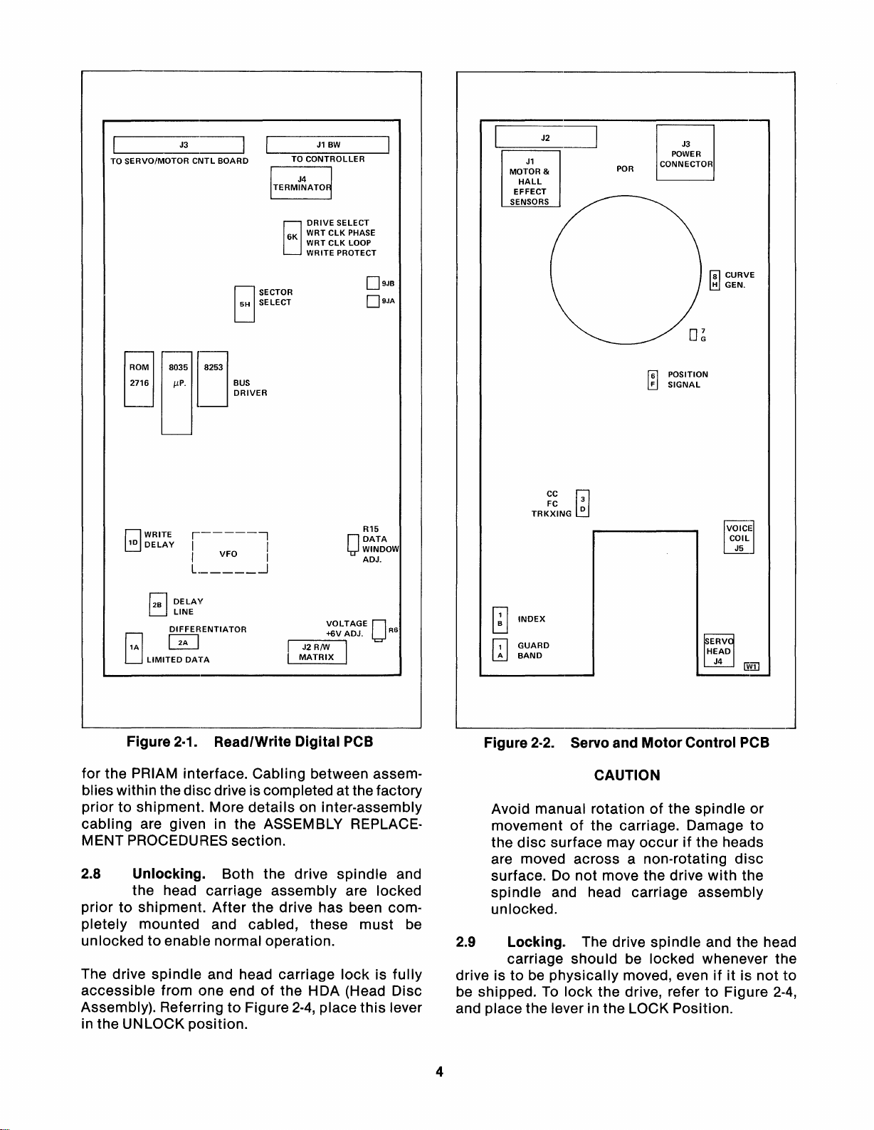
2.7 Cabling. The power cable should
motor
stalled
control board (See Figure
to
connector
J3 on the servo and
2.2).
The
DC
be
in-
volt-
ages required at the respective pins on J3 are
to
listed in the 3.18.2 section. Interface cables
host
system are described in the
ing each
of
the available interface options. Figure
sections
the
cover-
2.3 shows how the interface cables are connected
3
____
TO
SERVO/MOTOR
0M
2716 IlP. BUS
tj
rJWRITE
~DELAY
J3_~
CNTL
lJ035
r------,
I
I I
L
BOARD
oSECTOR
oSELECT
J253
DRIVER
VFO
..J
EJ
I
J1
TO
CONTROLLER
DRIVE
6K
WRT
• WRT
WRITE PROTECT
BW
SELECT
CLK
CLK
PHASE
LOOP
O
D9JB
D9JA
R15
DATA
WINDOW
ADJ.
J1
MOTOR &
HALL
EFFECT
SENSORS
TRKXING
J2
CC
FC
"-;:===~
~
W
3
0
POR
POWER
CONNECTOR
f61
POSITION
F
~
SIGNAL
J3
f8l
CURVE
l!!1
GEN.
VOICI
=
COIL
J5
J
r;;l
DELAY
L:J
LINE
o
LJ
0ENTIATOR
LIMITED
DATA
Figure 2·1. Read/Write
Digital
PCB
for the PRIAM interface. Cabling between assem·
blies within the discdrive is completed atthe factory
priortoshipment. More
cabling
are given in the ASSEMBLY REPLACE-
details
on inter-assembly
MENT PROCEDURES section.
2.8 Unlocking. Both the drive
spindle
and
the head carriage assembly are locked
priortoshipment.
pletely
mounted and cabled, these
After
the drive has been com·
must
be
unlockedtoenable normal operation.
The drive spindle and head carriage
accessible
from one endofthe HDA (Head Disc
Assembly). ReferringtoFigure 2·4, place
in the UNLOCK
position.
lockisfully
this
lever
o
INDEX
GUARD
IT]
BAND
Figure 2·2. Servo and
Motor
Control PCB
CAUTION
Avoid manual rotationofthe
spindle
movementofthe carriage. Damage
the
disc
surface may
occurifthe heads
are moved across a non-rotating
surface. Do
spindle
not
move the drive
with
and head carriage assembly
unlocked.
2.9 Locking. The drive
spindle
and the head
carriage shouIdbe locked whenever the
drive istobe
be shipped.
physically
To
lock
moved, evenifitisnot
the drive, refertoFigure
and place the lever in the LOCK Position.
or
to
disc
the
to
2-4,
4
•
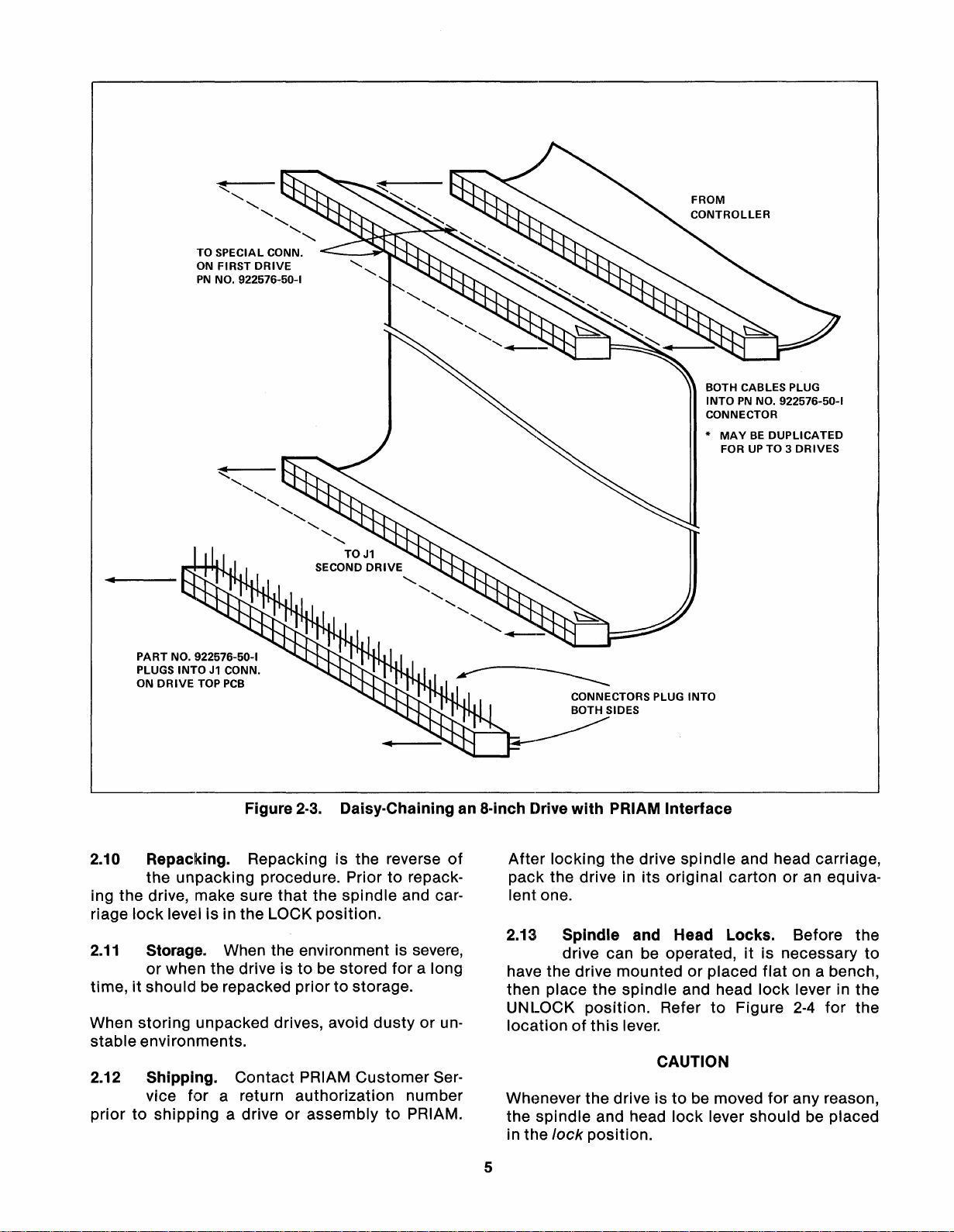
PART NO. 922576-50-1
PLUGS
INTOJ1CONN.
ON
DRIVE
~
........
.........
........
",
TO SPECIAL CONN.
ON FIRST
PN
TOP
DRIVE
NO. 922576-50-1
................
................
................
PCB
........
........
........
SECOND
TOJ1
DRIVE
FROM
CONTROLLER
BOTH CABLES PLUG
INTOPNNO. 922576-50-1
CONNECTOR
*
MAYBEDUPLICATED
FORUPTO 3
DRIVES
,
........
........
........
........
........
'...--
•
Figure
2.10 Repacking. Repacking is the reverse
the
unpacking
ing the drive, make sure
riage
lock
level is in the LOCK
2.11
Storage. When the environment is severe,
or
when
the
drive istobe stored
time,itshould be repacked
When
stable
2.12 Shipping.
priortoshipping
storing
unpacked drives, avoid
environments.
vice
for
a return
a driveorassemblytoPRIAM.
Contact
2-3.
Daisy-Chaining an a-inch Drive
procedure. Priortorepack-
that
the
spindle
and car-
position.
for
a long
priortostorage.
dustyorun-
PRIAM
authorization
Customer
number
of
Ser-
with
After
pack
PRIAM
locking
the drive
the drive in
Interface
its
original
spindle
lent one.
2.13
Spindle
and Head Locks. Before the
drive can be operated,itis necessary
have the drive mountedorplaced
then place the
UN
LOCK
locationofthis
spindle
position.
lever.
and head
Refer
CAUTION
Whenever the drive istobe moved
the
spindle
in the
lock
and head
position.
lock
5
and head carriage,
cartonoran equiva-
to
flat
on a bench,
lock
lever in the
to
Figure
2-4
for
any reason,
for
the
lever should be placed

;iiiiiiiiiiiiiiiii';_iiiiiiHi
iiiiiiiiiiiiiiiiiiiiiiiiiii_iiiiiiii_=
o
_
SPINDLE LOCK
Figure 2·4.
2.14 Powering Up/Down. The
dure
for
powering up the drive depends on
the
interface
option
present:
LocationofHead and Spindle
exact
If the drive has a standard PRIAM interface,
apply
DC
power,
select
the drive (via the -DRIVE
SELECT lines) and issue a Sequence Up
command.
If the drive has an SMD interface, apply
power,
select
the drive (via the UNIT SELECT
lines), then bring PICK and HOLDtoground.
If
the drive has an ANSI interface,
power,
select
the drive (via the SELECT/ATTEN-
apply
TION lines), then issue a Spin Up command.
Similarly, the procedure
depends on the interface
If
the drive has a standard PRIAM interface, issue a Sequence Down
nectDCpower
supply.
for
powering
option
command
down
present:
and discon-
If the drive has an SMD interface, remove the
ground from PICKorHOLD and
disconnect
powersupply.
proce-
DC
DC
also
DC
Lock
If the drive has an ANSI interface, issue a Spin
Down command and disconnectDCpowersupply.
2.15 Performance Check. The
following
cedures are recommended as an
check
a.
for
properoperation on the
disc
drive:
Watch for the drivetobecome Ready.Ifno faults
are detected during the power up sequence,
this
will
take
about30seconds.Ifa
tected
Ready
will
processor
that
speed, READY
tation
b.
Check the head positioning operation by issuing
seek commands. The
(by the
will
safety
be
inhibited
be reported. If,
within
the
spindle
will
will
stop.
circuits
within
and a
after
two
minutes, the micro-
the drive is unabletosense
is
rotating
be
inhibited
at the
following
fault
the drive),
fault
condition
specified
and
spindle
seek pattern
suggested:
From 000to001to000to002to000to003
000to004to000to005to000
cylinder
c.
Check
address.
for
proper
data
transfer
...tomaximum
operation by writ-
pro-
initial
is de-
ro-
is
to
6

ing and then reading data with each read/write
head.
CAUTION
Write operations alter previously recorded data
Most
disc
s/ystems require a formatted
disc
be-
fore datatransfer can be performed.
A
disc
surface
with
each
the location
disc
of
defect
defects
map is supplied by PRIAM
drive. The defect map indicates
discovered during manufacturing and testing. A defect location is speci'fied by the numberofbyte
positions
from the
index mark.
7

NOTES
8
3. FUNCTIONAL DESCRIPTION
3.1
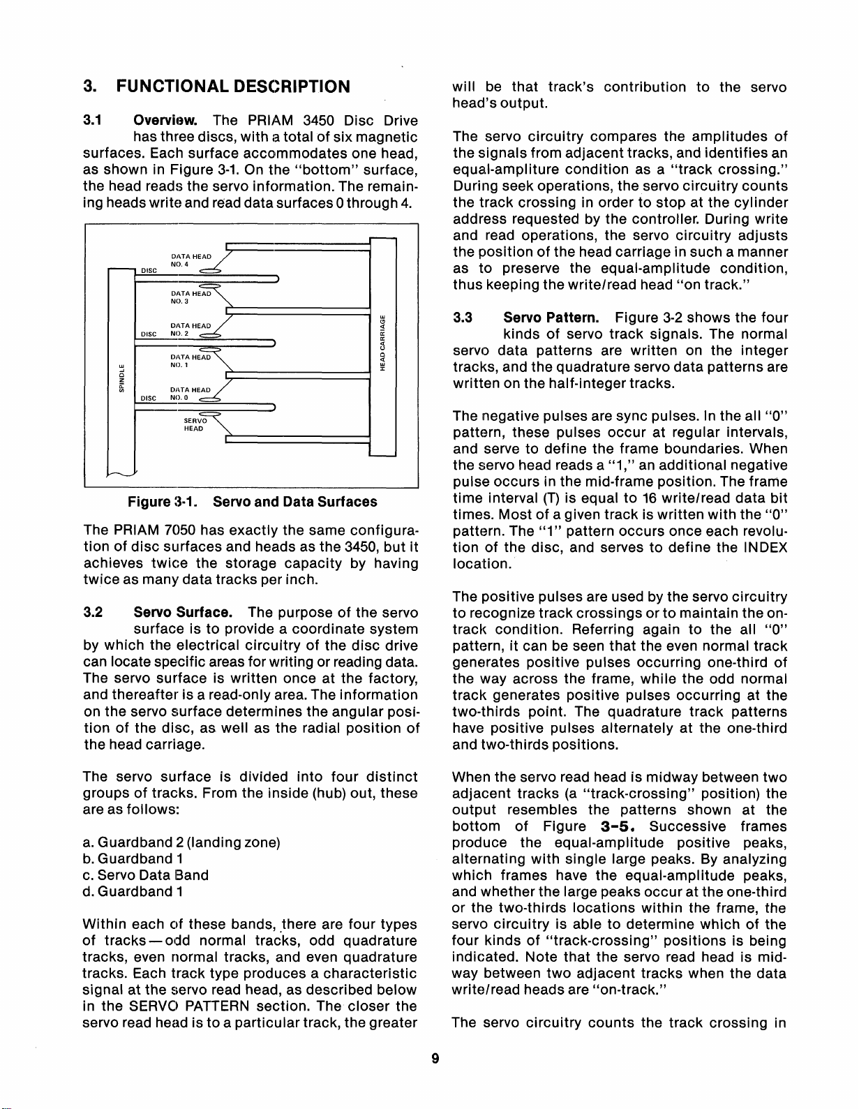
surfaces. Each surface accommodates one head,
as shown in Figure
the head reads the servo information. The remaining heads write and read datasurfaces0 through
Overvh!w. The PRIAM 3450 Disc Drive
has three discs, with a total
3-1.
On the
DATAH~
NO.4
DISC
-
DATAH~
NO.3
DIHAHE~
NO.2
DISC
DATAHE~
w
....
0
Z
g;
NO.1
DIHAHE~
NO.O
DISC
SER\~
HEAD
I
)
)
"bottom"
)
of
six magnetic
surface,
4.
r---
w
t:l
«
~
«
u
0
~
:I:
-
.....----....
Figure
The PRIAM 7050 has exactly the same configuration
of
disc
achieves
twice
as many data tracks per inch.
3.2
by which the electrical
can locate spe'cific areas for writing or reading data.
The servo surface is written once at the factory,
and thereafter is a read-only area. The information
on the servo surface determines the angular posi-
of
tion
the head carriage.
:~·1.
Servo and Data Surfaces
surfaces and heads as the
twice
the storage capacity by having
3450,
but
Servo Surface. The purposeofthe servo
surface is
the disc, as well as the radial position
to
provide a coordinate system
circuitryofthe
disc
drive
of
will
be
that track's contribution
to
the servo
head's output.
The servo
circuitry
compares the amplitudes
of
the signals from adjacent tracks, and identifies an
equal-ampliture
During seek operations, the
the track crossing in order
condition
as a
"track
servo
to
stop at the cylinder
crossing."
circuitry
counts
address requested by the controller. During write
and read operations, the servo
the position
as
to
of
the head carriage in such a manner
preserve the equal-amplitude condition,
thus keeping the write/read head
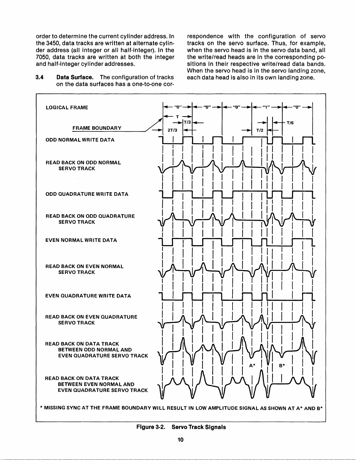
3.3
Servo Pattern. Figure
kinds
of
servo track signals. The normal
circuitry
"on
3-2
shows the four
adjusts
track."
servo data patterns are written on the integer
tracks, and the quadrature servo data patterns are
written on the half-integer tracks.
The negative pulses are sync pulses.
pattern, these pulses
occur
at regular intervals,
the all
"0"
In
and serve to define the frame boundaries. When
the servo head reads a
"1,"anadditional negative
pulse occurs in the mid-frame position. The frame
(T)
time interval
is equalto16
times. Mostofa given track is written
pattern. The
it
tion
of
"1"
pattern occurs once each revolu-
the disc, and servestodefine the INDEX
write/read data
with
the
bit
"0"
location.
The positive pulses are used by the servo
to
recognize track crossings ortomaintain the on·
track condition. Referring again
to
circuitry
the all
"0"
pattern,itcan be seen that the even normal track
generates positive pulses occurring one-third
of
the way across the frame, while the odd normal
track generates positive pulses occurring at the
two-thirds point. The quadrature track patterns
have positive pulses alternately at the one-third
and two-thirds positions.
The servo surface is divided into four
distinct
groupsoftracks. From the inside (hub) out, these
are as follows:
a.
Guardband 2(landing zone)
b.
Guardband 1
c.
Servo Data Band
d.
Guardband 1
Within each
of
tracks- odd normal tracks, odd quadrature
of
these bands, ,there are four types
tracks, even normal tracks, and even quadrature
tracks. Each track type produces a characteristic
signal at the
in the SERVO
servo read
servo read head, as described below
PATTERN
section. The closer the
head istoa particular track, the greater
When the servo read head is midway between
adjacent tracks(a"track-crossing"
output
bottom
resembles the patterns shown at the
of
Figure
3-5.
Successive frames
position) the
produce the equal-amplitude positive peaks,
alternating
with
single large peaks. By analyzing
which frames have the equal-amplitude peaks,
and whether the large peaks
or the two-thirds locations
servo
circuitry
four kinds
is abletodetermine whichofthe
of
"track-crossing"
occur
at the one-third
within
the frame, the
positions is being
indicated. Note that the servo read head is mid-
two
way between
write/read heads are
The servo
circuitry
adjacent tracks when the data
"on-track."
counts the track crossing in
9
two
ordertodetermine the current cylinderaddress.
the 3450, data tracks are written at alternate cylinder address (all integer or all half-integer).
7050,
data tracks are written at both the integer
In
the
and half-integer cylinder addresses.
3.4 Data Surface. The configuration
of
tracks
on the data surfaces has a one-to-one cor-
In
respondence with the configuration
of
servo
tracks on the servo surface. Thus, for example,
when the servo head is in the servo data band, all
the write/read heads are in the corresponding positions
in their respective write/read data bands.
When the servo head is in the servo landing zone,
each data head is also in
its
own landing zone.
LOGICAL
ODD
READ BACKONODD
ODD
READ BACKONODD
EVEN
READ BACK ON EVEN
FRAME
FRAME
NORMAL
SERVO
QUADRATURE
SERVO
NORMAL
SERVO
WRITE
TRACK
TRACK
WRITE
TRACK
BOUNDARY
DATA
NORMAL
WRITE
DATA
QUADRATURE
DATA
NORMAL
EVEN
QUADRATURE
READ BACKONEVEN
SERVO
READ
BETWEEN ODD
EVEN
READ
BETWEEN EVEN
EVEN
* MISSING SYNCATTHE FRAME
TRACK
BACKONDATA
QUADRATURE
BACKONDATA
QUADRATURE
WRITE
QUADRATURE
TRACK
NORMAL
SERVO
TRACK
NORMAL
SERVO
DATA
AND
TRACK
AND
TRACK
BOUNDARY
WILL
RESULTINLOW
AMPLITUDE
Figure 3·2. Servo Track Signals
10
SIGNAL
AS SHOWNATA*
AND
B*
The write/read
utively,
edgeofthe disc. Each write/read
vided
tors can be adjusted by the user through
settingsonthe
in the INSTALLATION section.
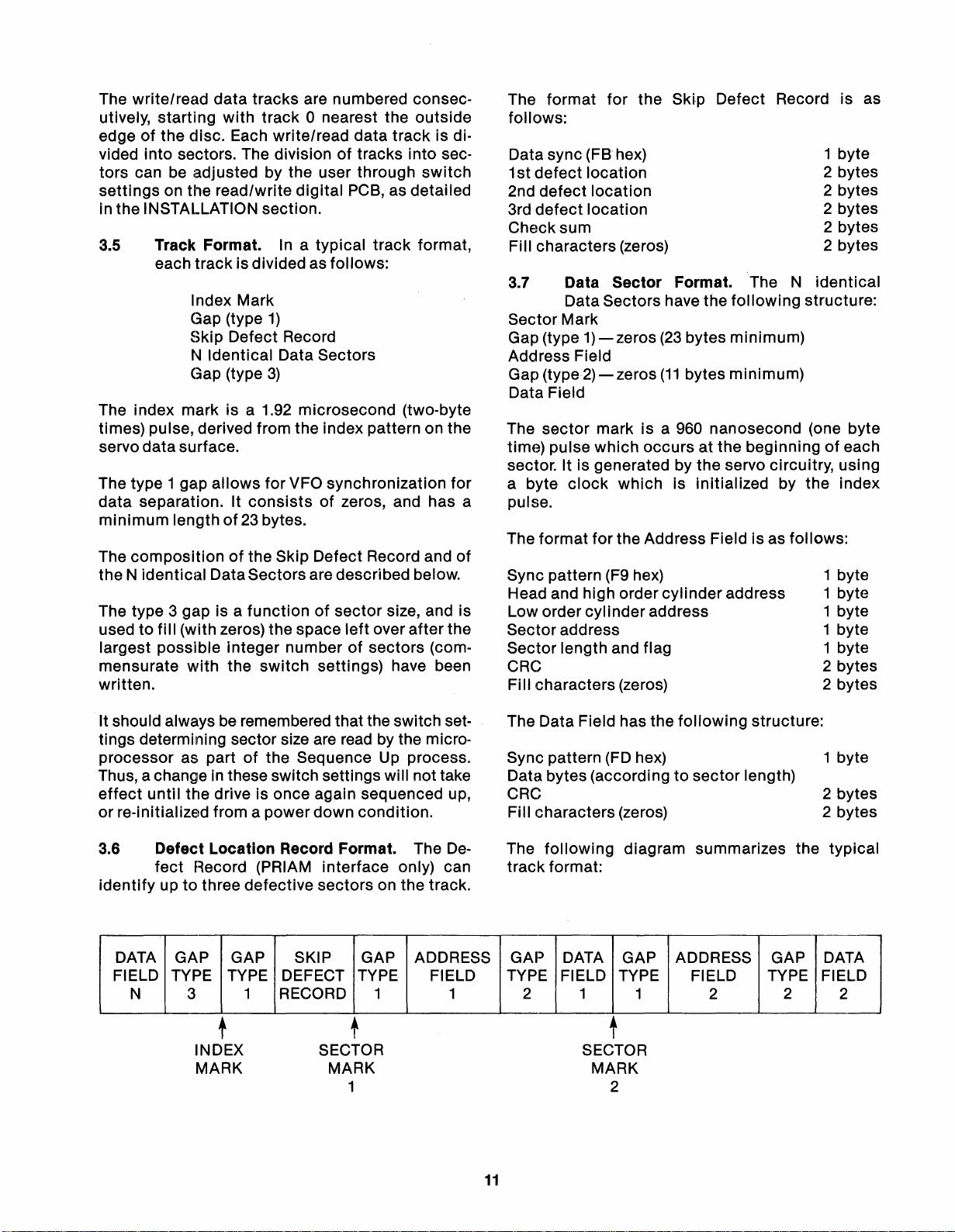
3.5 Track Format. In a
The index mark is a 1.92
times) pulse, derived from the index pattern on the
servo
The type 1 gap
data
minimum
The
theNidentical
The type 3 gap is a
usedtofill
largest
mensurate
written.
starting
into
each
data
separation. It
compositionofthe Skip Defect Record and
possible
data
tracks
with
sectors. The divisionoftracks
read/write
track
isdivided as
Index Mark
Gap (type
SkiP Defect Record
N
Identical
Gap (type
surface.
allows
consistsofzeros, and has a
lengthof23
DataSectors are described below.
functionofsector
(with zeros) the space
integer
with
the
are numbered consec-
track
0 nearest the
data
digital
1)
Data Sectors
3)
microsecond
for
VFO synchronization
bytes.
numberofsectors
switch
PCB, as detailed
typical
settings) have been
track
follows:
left
over
outside
track
is di-
into
sec-
switch
format,
(tWO-byte
for
of
size, and is
after
the
(com-
The
format
follows:
Data sync (FB hex)
1stdefect
2nd
defect
3rd
defect
Checksum
Fill characters (zeros)
3.7 Data
Sector
Gap (type
Address Field
Gap
(type2)-zeros
Data Field
The
sector
time) pulse
sector. It is generated by
a byte
pulse.
The
format
Sync pattern (F9 hex)
Head and high order
Low order
Sector
Sector
CRC
FiIIcharacters (zeros)
address
for
the
Ski·p
location
location
location
Sector
Data Sectors have the
Mark
1)-zeros
markisa 960 nanosecond (one byte
which
clock
length and flag
which
for
the Address Field is as
cylinder
Format. The N
(23
(11
occursatthe beginningofeach
is
cylinder
address
Defect Record is as
following
bytes
minimum)
bytes
minimum)
the
servo circuitry, using
initialized
address
structure:
by the index
follows:
1 byte
2 bytes
2 bytes
2 bytes
2 bytes
2 bytes
identical
1 byte
1 byte
1 byte
1 byte
1 byte
2 bytes
2 bytes
It should alwaysberemembered that the switch set-
tings determining sector size are read by the micro-
processor as partofthe Sequence Up process.
Thus, a change in these switch settings will not take
effect
or
3.6 Defect
identifyupto
until
the drive is once again sequenced up,
re-initialized from a power
Location
fect
Record (PRIAM
three
defective
DATA
FIELD TYPE TYPE DEFECT TYPE FIELD TYPE FIELD TYPE FIELD TYPE FIELD
GAP GAP SKIP GAP ADDRESS GAP DATA GAP ADDRESS GAP DATA
N 3
1 RECORD 1 1 2 1
t
INDEX
MARK
down
condition.
Record Format. The
interface
sectors
only) can
on the track.
t
SECTOR
MARK
1
De-
The Data Field has the
Sync pattern (FD hex)
Data bytes (accordingtosector
CRC
Fill characters (zeros)
The
track
following
format:
diagram summarizes
t
SECTOR
MARK
2
following
1 2
structure:
1 byte
length)
2 bytes
2 bytes
the
2
typical
2
11

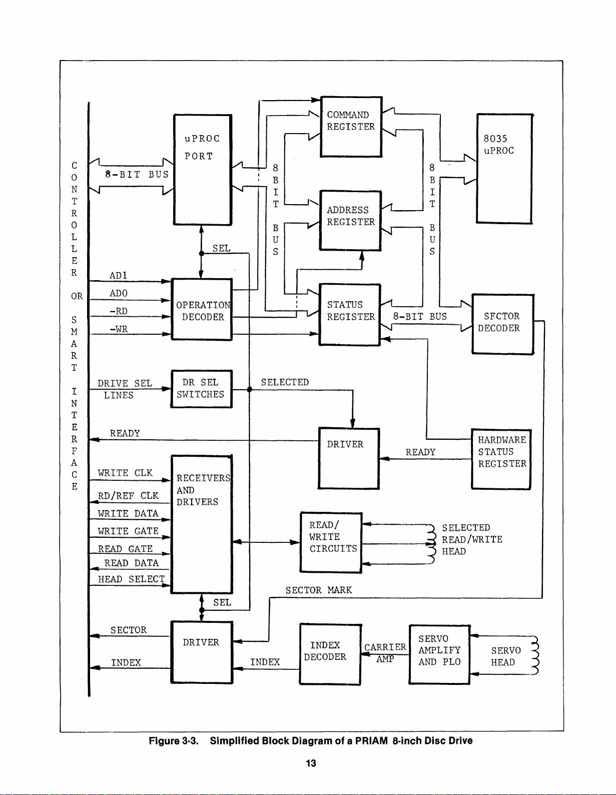
3.8
Overview. Figure
3-3
is a simplified
diagramofa PRIAM 8-inch
disc
block
drive with
the standard PRIAM interface. The overall organization shown is the same for all drives in the
family. However, the namesofthe
face signals vary as a function
specific
of
the interface
8"
interoption present.
The
disc
drive has its own
which controls the sequencing
tions
that
3.9
occur
Drive Selection. The
in the drive.
(8035)
disc
microprocessor,
of
all the opera-
drive must
be
properly selected beforeitwiIIrespond
anyofthe signals on the controller interface. On
the standard PRIAM interface, this is accomplished
t11e
by placing the proper address on
SELECT
1-4
lines.
On
the SMD interface, the
proper address is placed on the UNIT SELECT
4 and 8 lines and the UNIT SELECT
tivated.
may
(below) describing the
The address
by
In
general, the interface linestobe used
be
determined by referring
of
an
individual drive is determined
switch
settings on the read/write digital
specific
TAG
to
interface involved.
DRIVE
1,
line is ac-
the section
PCB,
as discussed in the INSTALLATION section. The
drive responds
its
when
switch-selected address matches that
to
the selection procedure only
placed on the interface by the controller.
3.10 Power Up/Down Sequences. When power
is applied, the Microprocessor Initialization
sequence occurs automatically. The microprocessor then goes
into
the idle state, in whichitmoni-
tors the controller interface for acommand.
The controller may then issue a Sequence
Up
commandtothe drive (the exact manner in which
this
is done depends on the interface option
present). The microprocessor recognizes
this
command and starts the spindle motor. When the
motor
is running at the proper speed, the micro-
processor reads the sector length switches, and
to
configures the drive
chosen sector length. Next
operate in terms
it
calls the
subroutine, which moves the heads
RSTRGO
to
cylinder
of
the
zero. It then enables the drive ready status, resets
to
the busy condition, and returns
the idle state.
The drive is'stopped by issuing a Sequence Down
to
command. This causes the heads
returntothe
landing zone, and stops the spindle motor.
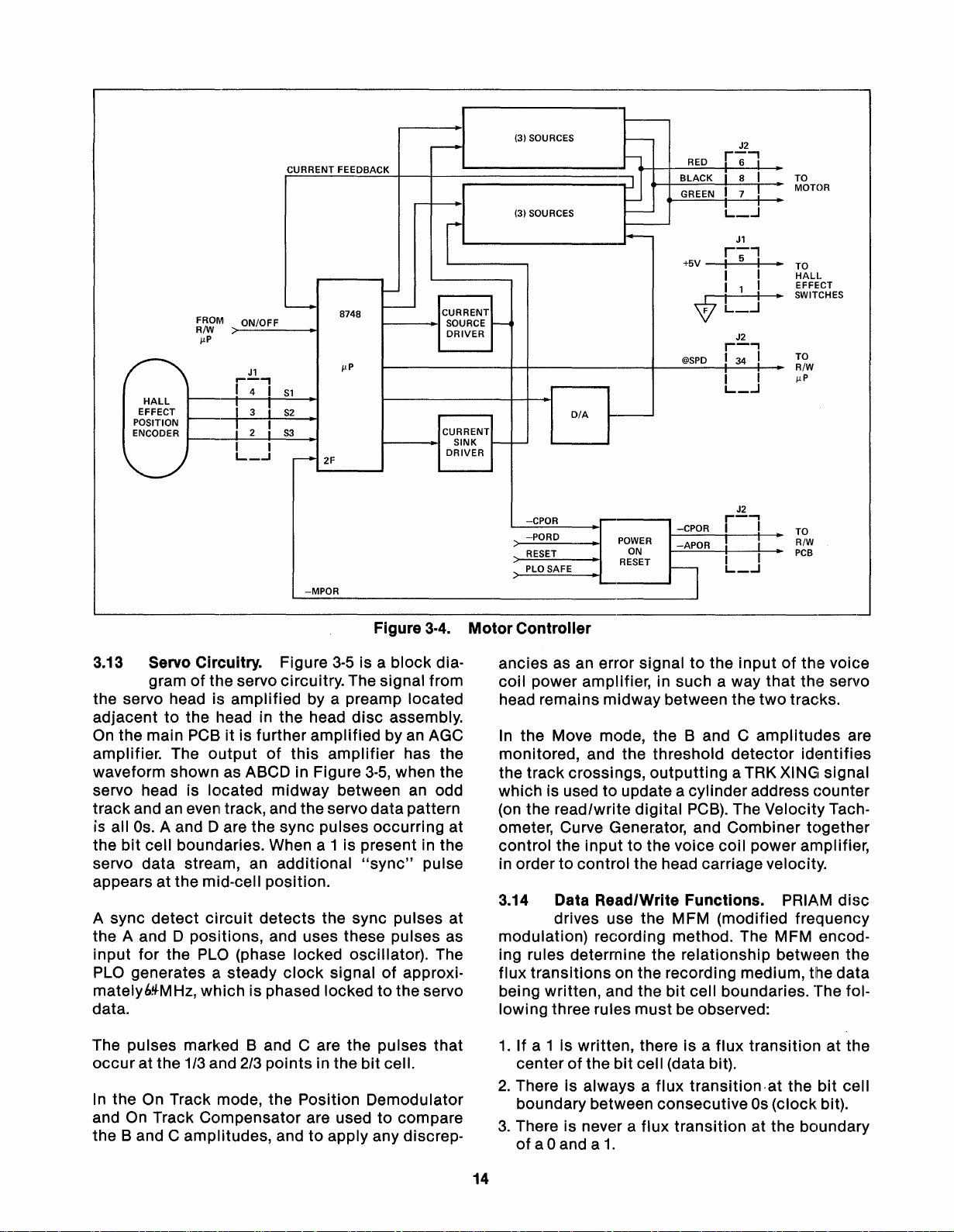
3.11
MotorControl Circuitry. The spindle motor
is a brushless (electronic commutating)
DC
permanent magnet
motor. The speed
of
the
to
2,
motor
taining Hall
Figure
is controlled by a closed-loop
3-4
effect
is a
sensors and a comparator.
block
diagramofthe motor control
circuit
con-
circuitry. The microprocessor sets the OFF signal
to
true
inhibit
spindle rotation, or falsetoallow
spindle rotation. The microprocessor monitors
of
the speed
up sequence, the
fied speed
operation, the
specified speed range, the microprocessor
spindle rotation. If, during the power
within
motor
one minute, or if, during normal
motor
does not reach
its
speci-
speed passes outsicJe the
will
set the Fault condition, restore the headstothe
landing zone, and
3.12 Seek Modes. The servo system has
main
inhibit
mocJes
the spindle rotation.
of operation -
On
Track mode
two
(also called Position mode) and Move mode.
Move mode becomes active when the drive is
to
commanded
move the heads. The microplrocessor receives the new target cylinder address and
the seek command, determines the direction
travel and the numberoftrackstobe
crossed, and
of
sets Move mode.
When the servo is in Move mode, a velocity profile
(produced by a digital-to-analog converter) is compared (via a summing junction) with the
output
an electronic tachometer, which indicates the
of
velocityofheadmotion. The difference signal from
the summing
junction
is fedtothe servo power
amplifiers, which control the voice coil motion.
The heads are driven toward the new cylinder
address. The servo
circuitry
crossings and decreases the velocity
motion as the selected cylinder is
When the heads are
within
monitors the track
of
approachE~d.
100
microinchesofthe
head
new cylinder, the On Track mode becomes active.
In
the On Track mode, the heads are held precisely
over the designated track. Any unintended head
movement is detected by the electronic tachom-
eter and fed
causes the servo power amplifiers
to
the summing junction. This in turn
to
adjust the
head position, so that the heads remain at the
desired location.
Servo safety
circuits
ing zone upon detection
or
if
both Move and
taneously. The safety
voice coil speed.
ceeded,
orifthe continuous position information
drive the headstothe land-
of
a low power condition,
On
Track modes
circuits
also
occur
monitor
simul-
the
If the specified speed is ex-
is lost, an Overspeed signal is established and the
servo power amplifiers are disabled. Seek Fault is
set
if
anyofthe above
conditions
develop.
12
C
o
N
T
R
o
L
L
E
R
OR
S
M
A
R
T
I
N
T
E
R
F
A
C
E
V1
B-BIT
........,-
ADI
ADO
-RD
-WR
DRIVE
LINES
READY
-
WRITE
_RD/REF
WRITE
WRITE
READ
_
READ
HEAD
BUS
SEL
CLK
CLK
DATA
GATE_
GATE
DATA
SELECI
uPROC
PORT
'"
V
-
-
OPERATION
DECODER
-
_
DR
..
SWITCHES
~
RECEIVERS
AND
DRIVERS
_
I
SEL
SEL
SEL
VL-.-
N--
-
-
-
--
~
COMMAND
REGISTER
r----v
8
I
I
B
I I
T
L-J
........
ADDRESS
--V
B
U
S
LL
i
,
;V
SELECTED
..
SECTOR
REGISTER
STATUS
REGISTER
-
DRIVER
READ/
WRITE
CIRCUITS
MARK
/l
~
.....-1
N
A
8-BIT
"'i
-
"'
_
~------~--~
8
B
T
B
U
S
BUS
~----~
READY
L-f'..
-
r---v-
--.1'.;
V
8035
uPROC
SFCTOR
DECODER
HARDWARE
STATUS
REGISTER
-
...
_
SECTOR
INDEX
DRIVER
INDEX
Figure 3·3. Simplified Block Diagram of a PRIAM a·inch Disc Drive
INDEX
DECODER
13
~ARRIER
AMP
SERVO
AMPLIFY
AND
PLO
-
SERVO
HEAD
~
~
"')
-<
FROM ON/OFF
RIW
>----
/-LP
r--,
HALL
EFFECT I 3 ,
POSITION I 2
ENCODER
t------0I-------.I
I 4 I
I!
I I
L_.J
CURRENT FEEDBACK
J1
S1
S2
,I
53
r--+
..
2F
-MPOR
8748
-
-
1-----1
1-----1
Ioo-.-------
CURRENT
SOURCE
1---4
DRIVER
CURRENT
SINK
r---""-
DRIVER
L.::£!CP~O~R
(3) SOURCES
...
D/A
--11---'
-PORD
RESET
PLO SAFE RESET
L..------I'
J2
h RED
~J.-+-l-----:....:.:;;.;;;;....--......-.:i:........a.-
POWER
ON
-CPOR
~--A-PO-R~!~-~I-
r--l
BLACK
+5V
~I
'V'
@SPD
r-;l
8 I TO
J1
r-'
I 5 I •
I I
I 1 I
I·
L_.J
J2
r-"
! 34 I
J2
r-l
I I
L_...J
MOTOR
TO
HALl.
EFFECT
SWITCHES
TO
R/W
/-LP
TO
R/W
PCB
I
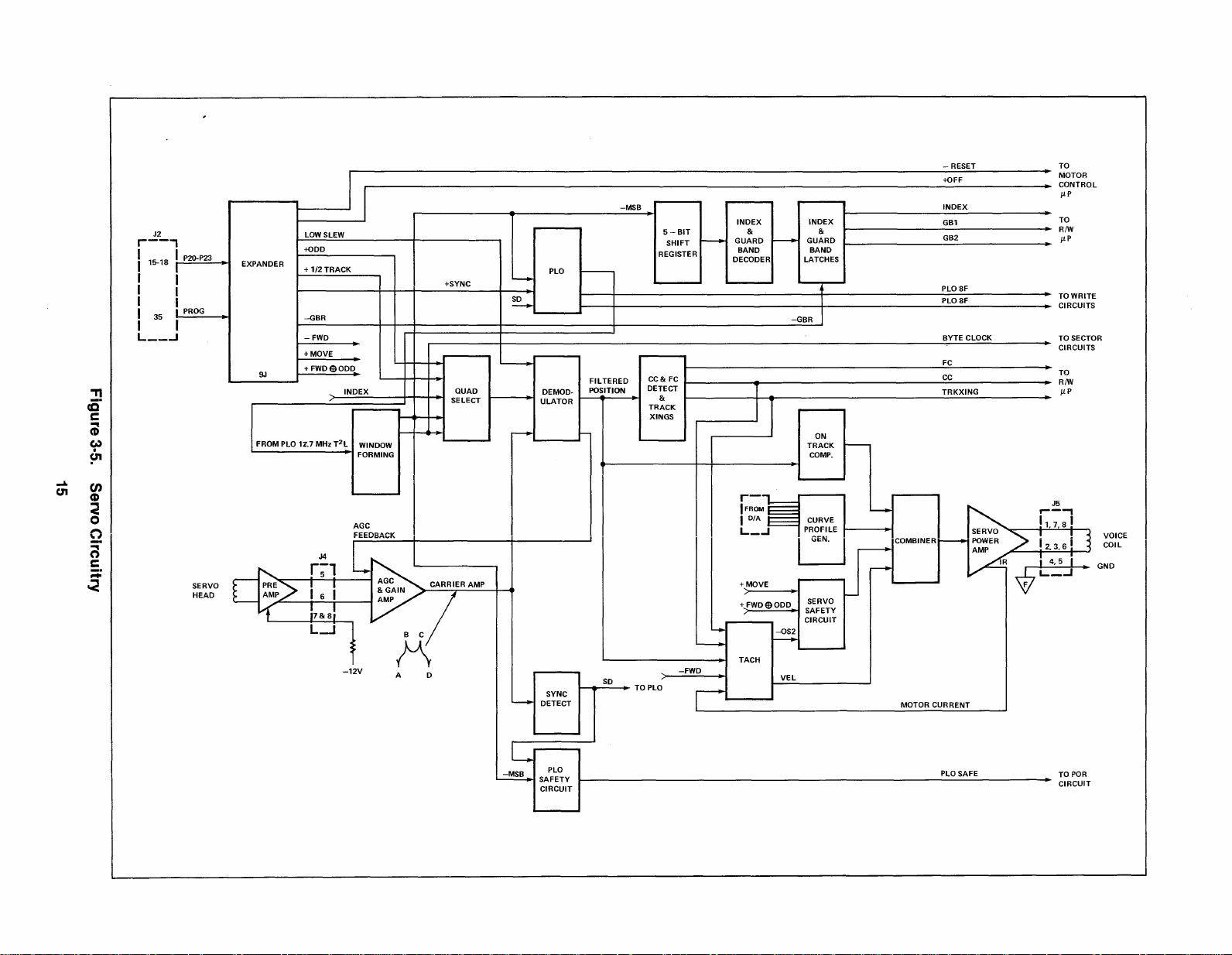
3.13 Servo Circuitry.
gram
of
the servo circuitry. The signal from
Figure
Figure
3-5
is a block dia-
3-4.
the servo head is amplified by a preamp located
to
adjacent
On
the main PCBitis further amplified byanAGC
amplifier. The
the head in the head
output
of
this
waveform shown as ABCD in Figure
servo head is located midway between
disc
amplifier
3-5,
assembly.
has the
when the
an
odd
track and an even track, and the servo datapattern
is aliOs. A and D are the sync pUlses occurring at
bit
the
cell boundaries. When
servo data stream, an additional
a1
is present in the
"sync"
pulse
appears at the mid-cell position.
A sync detect
circuit
detects the sync pulses at
the A and D positions, and uses these pulses as
input for the
PLO
generates a steady
PLO
(phase locked oscillator). The
clock
signalofapproximately69-MHz, which is phased lockedtothe servo
data.
The pulses marked
occur
at the 1/3 and
In
the On Track mode, the Position Demodulator
and
On
Track Compensator are usedtocompare
the
Band
C amplitudes, andtoapply any discrep-
Band
2/3
points in the
C are the pulses that
bit
cell.
Motor
Controller
ancies as an error signaltothe inputofthe voice
coil power amplifier, in such a way that the servo
two
head remains midwaybetween the
In
the Move mode, the
monitored, and the threshold
the track crossings,
Band
outputting
C amplitudes are
detector
aTRK XING signal
tracks.
which is used to update a cylinder address Gounter
(on the read/write digital
PCB).
The Velocity Tachometer, Curve Generator, and Combiner together
control the
in order
inputtothe voice coil power amplifier,
to
control the head carriage velocity.
3.14 Data Read/Write Functions. PRIAM
drives use the MFM (modified frequency
modulation) recording method. The MFM encoding rules determine the relationship between the
flux transitions on the recording medium,
bit
being written, and the
lowing three rules must
cell boundaries. The fol-
be
observed:
1.Ifa 1 Is written, there is a flux transition at the
of
the
bit
center
2.
There is always a flux transition-at the
boundary between consecutive
3.
There is never a flux transition at the boundary
of
a0 and a
cell (data bit).
1.
Os
(clock bit).
identifies
disc
the data
bit
cell
14
..
c.n
~.
c
;
w
(JJ
CD
o
Q
n
c
::;:
~
"T1
~
<
J2
r--,
I I P20-P23
I
15-18
r--
I I
I I
I I
l
PROG
I
I
35
I
L
__
..J
SERVO
HEAD
IJ
LOW SLEW
EXPANDER I I DECODER LATCHES
+ODD REGISTER
+
1/2
TRACK
-GBR -GBR
- FWD BYTE CLOCK
+ MOVE
+
9J
It-
FWDeODD
.
p
•
INDEX
+SYNC _
I
I
QUAD
SELECT
~
PLO
L.-.-
~
DEMOD- POSITION DETECT T
ULATOR
_,I
~
5S~I~~
r-----.
FIL
TERED
CC
& FC
T & I
TRACK
~I
INDEX
GU:RD
BAND
----
INDEX
GU:RD
BAND
---.
I
I
IXINGS
FROM PLO
12'.7 MHz
T2L
I WINDOW I I r-I h I
FORMING I - I
AGC
FEEDBACK
II
r-
I
FROM
lOlA
L_...i
I ITRO:CK
COMPo
CURVE I
PROFILE
o
+ MOVE
~
,
VEL
SERVO
SAFETY
CIRCUIT
-12V
B C
K
A
+
FWDeODD
--
l..+
L-
o
SYNC
~
DETECT
SO
I.
• TO PLO
-FWD
TACH
r'
i
t--
~
~
::~'
GBl
GB2
PLO 8F
PL08F
FC
CC
TRKXING
dOOM""'"
t-
MOTOR CURRENT
TO
MOTOR
CONTRO
/lP
TO
RIW
/lP
TO WRITE
CIRCUITS
TO SECTOR
CIRCUITS
TO
RIW
/lP
GND
VOICE
COIL
L
I
-MSB.1SAFETY
CIRCUIT
PLO
PLO SAFE
POR
TO
CIRCUIT
Figure
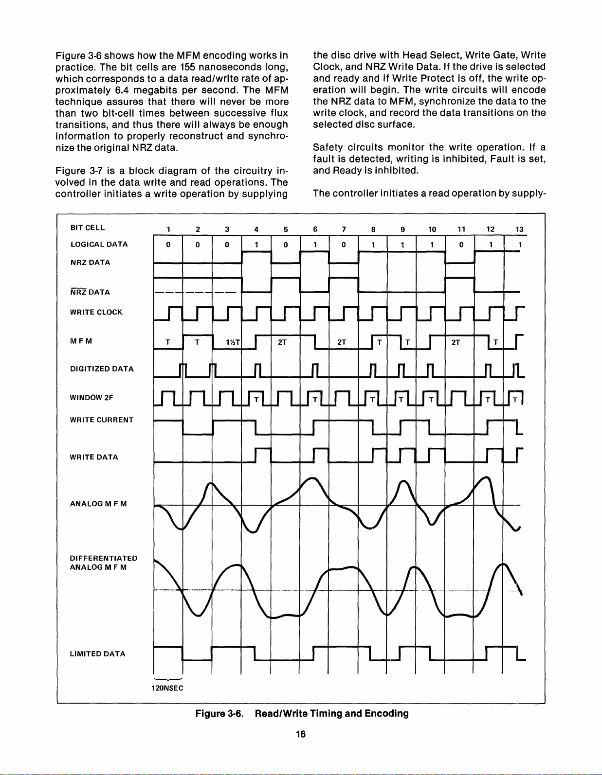
practice. The
which
proximately
technique
than
transitions, and
3-6
shows
how the MFM encoding works in
bit
cells
correspondstoa
6.4
megabits
assures
two
bit-cell
times
thus
are
data
that
there
informationtoproperly
nize the original NRZdata.
Figure
volved in the
controller
3-7
is a
initiates
BIT
CELL
LOGICAL
NRZ
NRZ
WRITE CLOCK
DATA
DATA
DATA
block
data
diagramofthe
write
a write operation by
o
155
nanoseconds long,
read/write rateofap-
per second. The MFM
there
will
never be more
between successive
will
always be enough
reconstruct
and synchro-
circuitry
flux
in-
and read operations. The
supplying
2
3
o
o
4
the
disc
drive
with
Head Select, Write Gate, Write
Clock, and NRZWrite Data. If the drive is selected
and ready andifWrite Protect is off, the
eration
the NRZ
write
selected
Safety
fault
will
begin. The
write
circuits
datatoMFM, synchronize the
clock, and record the
disc
surface.
circuits
is detected,
monitor
writingisinhibited,
data
the write operation. If a
transitions
write
will
encode
datatothe
on the
Fault is
op-
se~t,
and Ready is inhibited.
The
controller
5
o
6 7
o
initiates
8
1
a read operation by supply-
10
9
1
11
12
o
MFM
DIGITIZED
WINDOW 2F
WRITE CURRENT
WRITE
ANALOG
DIFFERENTIATED
ANALOG
DATA
DATA
M F M
M F M
LIMITED
DATA
-.-
120NSEC
Figure
3-6.
Read/Write
16
Timing
and Encoding
 Loading...