

Page 1

SOFTWARE VERSION 3.7
WWW.PRG.COM
MBOX® MEDIA SERVER
USER MANUAL
Page 2

AutoPar®, Bad Boy®, Best Boy 4000®, PRG Series 400®, MBOX®, MBOX Extreme®, OHM™, Super Node™, V476®, V676®, Virtuoso®,
Virtuoso® DX, Virtuoso® DX2, and VL6C+™ are trademarks of Production Resource Group, LLC, registered in the U.S. and other countries.
Mac®, QuickTime® and FireWire® are registered trademarks of Apple Computer, Inc.
All other brand names which may be mentioned in this manual are trademarks or registered trademarks of their respective companies.
This manual is for informational use only and is subject to change without notice. Please check www.prg.com for the latest version.
PRG assumes no responsibility or liability for any claims resulting from errors or inaccuracies that may appear in this manual.
Mbox® Media Server User Manual
Version as of: January 6, 2014
PRG part number: 02.9800.0001.37
Production Resource Group
Dallas Office
8617 Ambassador Row, Suite 120
Dallas, Texas 75247
www.prg.com
©2013-2014 Production Resource Group, LLC. All Rights Reserved.
Mbox® Media Server User Manual
Page 3

TABLE OF CONTENTS
Introduction
About This Manual........................................................................................................................................................................ 1
Important Note About Consoles!.................................................................................................................................................. 1
Additional Documentation ............................................................................................................................................................ 1
Training Videos ............................................................................................................................................................................. 2
Customer Service......................................................................................................................................................................... 2
Chapter 1. Overview
General Overview
Important Terminology.................................................................................................................................................................. 4
Features........................................................................................................................................................................................ 4
Concepts of Operation................................................................................................................................................................. 6
Components
Mbox Extreme Case Assembly .................................................................................................................................................... 7
Dual I/O Module ........................................................................................................................................................................... 8
Auxiliary Input Panel ................................................................................................................................................................... 10
Mac Computer............................................................................................................................................................................ 11
Fixture Descriptions
Mbox Environment Concept....................................................................................................................................................... 13
Fixture and Layer Overview........................................................................................................................................................ 14
Fixture, Layer and Parameter Details ......................................................................................................................................... 16
Ambient Light and Spot Lights 1 - 4 ................................................................................................................................... 16
Camera ............................................................................................................................................................................... 16
Shutter Control.................................................................................................................................................................... 16
Keystone Control................................................................................................................................................................. 16
Layers: Texture + Object..................................................................................................................................................... 17
Operating Modes
Mbox Designer v3.7 Modes ....................................................................................................................................................... 18
Single Output Mode ............................................................................................................................................................ 18
Dual Independent Mode...................................................................................................................................................... 18
Panoramic Wide Mode........................................................................................................................................................ 19
Panoramic Dual Mode......................................................................................................................................................... 19
Chapter 2. Installation and Power-Up
Sample Configuration Diagrams
Overview..................................................................................................................................................................................... 22
DMX512 Input Configuration: Single Media Server with DMX512 Devices ............................................................................... 22
Art-Net Input Configuration: Network Switch and Multiple Media Servers................................................................................ 23
Output Configuration: Single Media Server with Plasma Display and LCD Projector................................................................ 24
Setup
Basic Setup and Connections.................................................................................................................................................... 25
Connecting the Stage Output..................................................................................................................................................... 26
Networking Multiple Mbox Extreme Servers.............................................................................................................................. 26
Getting Started
Power-Up Overview.................................................................................................................................................................... 27
Power-Up Procedure.................................................................................................................................................................. 28
Mbox Daemon............................................................................................................................................................................ 28
Patching Fixtures
Patching Overview...................................................................................................................................................................... 29
Layer Guidelines......................................................................................................................................................................... 29
Parameter Mapping.................................................................................................................................................................... 30
Playing Back Video - Quick Start ............................................................................................................................................... 33
MBOX® MEDIA SERVER USER MANUAL III
Page 4

Chapter 3. Operation
Media Content
File Type Specifications .............................................................................................................................................................. 36
Recommended Practices ........................................................................................................................................................... 36
Media Content Management...................................................................................................................................................... 37
Folder and File Numbering ......................................................................................................................................................... 38
Additional Media Content Organization Guidelines.................................................................................................................... 39
Adding Media Content................................................................................................................................................................ 40
Grouped Content........................................................................................................................................................................ 41
Description .......................................................................................................................................................................... 41
Usage .................................................................................................................................................................................. 41
Configuration/Setup ............................................................................................................................................................ 42
Creating and Viewing Content Thumbnails ................................................................................................................................ 43
Console Interface........................................................................................................................................................................ 43
Viewing Thumbnails in a Browser............................................................................................................................................... 44
Application Window
Overview ..................................................................................................................................................................................... 45
Setup .......................................................................................................................................................................................... 46
Setup: Control ..................................................................................................................................................................... 47
Setup: Window Mode.......................................................................................................................................................... 47
Setup: Fullscreen Mode ...................................................................................................................................................... 48
Setup: Rendering................................................................................................................................................................. 50
Setup: License..................................................................................................................................................................... 50
Setup: Texture Size ............................................................................................................................................................. 50
Setup: Screen Selection (Screen Arrangement).................................................................................................................. 50
Setup: Network.................................................................................................................................................................... 51
Setup: Video Inputs............................................................................................................................................................. 51
Setup: I/O Module ............................................................................................................................................................... 52
Setup: Options .................................................................................................................................................................... 52
Setup: Media Log (Media Errors)......................................................................................................................................... 53
Heads Up Displays (HUDs)
Overview ..................................................................................................................................................................................... 54
Using the HUDs .......................................................................................................................................................................... 55
Dual I/O Module
Operation Overview .................................................................................................................................................................... 56
Connected Display Devices and EDID ....................................................................................................................................... 57
Overview.............................................................................................................................................................................. 57
Switching Between Modes.................................................................................................................................................. 58
Switching Between Standard EDID or Capturing EDID ...................................................................................................... 59
SDI Output (SD - Standard Definition & HD - High Definition).................................................................................................... 61
Genlock (Generator Lock)........................................................................................................................................................... 62
Enhancing Mbox Performance
Recommended Practices ........................................................................................................................................................... 64
Chapter 4. Advanced Features
3D Objects and Digital Gobos
About 3D Models and Digital Gobos (Objects)........................................................................................................................... 66
Lighting................................................................................................................................................................................ 66
Vertex Array Files (Compiling) ............................................................................................................................................. 66
Preloading 3D Objects ........................................................................................................................................................ 67
Normalization....................................................................................................................................................................... 67
DHA and VARI*LITE Digital Gobos ............................................................................................................................................. 68
Creating Custom Digital Gobos.................................................................................................................................................. 69
Overview.............................................................................................................................................................................. 69
Scale-To-Fit vs. Arbitrary Fit................................................................................................................................................ 69
Creating a Digital Gobo with Adobe Illustrator CS5............................................................................................................ 69
Animated Digital Gobos.............................................................................................................................................................. 74
EuroFlag (002/000) .............................................................................................................................................................. 74
IV MBOX® MEDIA SERVER USER MANUAL
Page 5

TV Screen v1.4 (002/001) .................................................................................................................................................... 75
Snow v1.2 (002/002) ........................................................................................................................................................... 76
Tunnel v1.1 (002/003).......................................................................................................................................................... 77
Flag v1.0 (002/004).............................................................................................................................................................. 77
Ring Stripe (002/005)........................................................................................................................................................... 78
Stripe Ring (002/006)........................................................................................................................................................... 78
Fisheye (002/007) ................................................................................................................................................................ 78
CylinderScreen (002/008).................................................................................................................................................... 79
MultiScreen Gobo (002/009) ............................................................................................................................................... 79
Fit To Screen (002/010)....................................................................................................................................................... 80
Animated Textures
Using Animated Textures (Animations)....................................................................................................................................... 81
Layer Copy
Using Layer Copy ....................................................................................................................................................................... 82
Drawmodes
Using Drawmodes ...................................................................................................................................................................... 83
Drawmode 16 - Orthographic View............................................................................................................................................ 84
The Stencil.................................................................................................................................................................................. 85
Layer Blending
Layer Blending Modes................................................................................................................................................................ 88
Special Effects
Decay.......................................................................................................................................................................................... 89
Fog ............................................................................................................................................................................................. 90
Text Files
Support for Text Files ................................................................................................................................................................. 91
Audio
Audio Output Features ............................................................................................................................................................... 92
Overview.............................................................................................................................................................................. 92
External Audio Tracks (Associated AIFF Files).................................................................................................................... 93
Embedded Audio Tracks (in QuickTime Movies) ................................................................................................................ 93
Synchronization
Timecode Synchronization (Timecode Sync Playmode)............................................................................................................ 94
Layer-To-Layer Synchronization................................................................................................................................................. 98
Kiosk Playmodes........................................................................................................................................................................ 99
Playout Playmodes..................................................................................................................................................................... 99
Alignment Rectangles
Using Alignment Rectangles .................................................................................................................................................... 100
Effects and Transitions
Effects and Transitions with Additional Input Files ................................................................................................................... 102
Adding Custom Effects or Transitions...................................................................................................................................... 103
Projection Mapping
Overview.......................................................................................................................
............................................................ 106
Chapter 5. Pixel-Mapping
Basic Pixel-Mapping
Overview................................................................................................................................................................................... 108
Setup ........................................................................................................................................................................................ 109
Advanced Pixel-Mapping
Creating Custom Fixtures......................................................................................................................................................... 115
Sampling Areas ........................................................................................................................................................................ 116
MBOX® MEDIA SERVER USER MANUAL V
Page 6

Chapter 6. Pixel Remapping
About Pixel Remapping
Overview ................................................................................................................................................................................... 120
Pixel Remapping Tutorial
Overview ................................................................................................................................................................................... 121
Projected Mapping ................................................................................................................................................................... 122
Discrete Mapping...................................................................................................................................................................... 135
Advanced Control
Triangle Strips and Triangle Fans (3D Vertex Array Screen Objects) ........................................................................................ 136
Glossary
Screen Object Control Types (Units, Typical Scale Value) ........................................................................................................ 138
Chapter 7. Video Input
Overview
Video Input................................................................................................................................................................................ 142
QuickTime Streaming with Video Capture Card ............................................................................................................... 142
USB/FireWire Input............................................................................................................................................................ 143
Configuration
Setting Video Input for Video Capture Card ............................................................................................................................. 144
Configuring Video Input within Mbox ....................................................................................................................................... 146
Chapter 8. Content Creation and Utilities
Creating Custom Content
Creating Movies and Audio Files.............................................................................................................................................. 150
File Extension .................................................................................................................................................................... 150
Codec ................................................................................................................................................................................ 150
Compression (Bit Rate)...................................................................................................................................................... 151
Frame Rate ........................................................................................................................................................................ 151
Resolution.......................................................................................................................................................................... 151
Audio ................................................................................................................................................................................. 151
Discrete Audio Support for Multichannel Audio ....................................................................................................................... 152
Alpha Channel in Movies – the Animation and ProRes 4444 Codecs ...................................................................................... 153
Applications for Content Creation ............................................................................................................................................ 153
Media Utility Applications
Mbox Media Lock..................................................................................................................................................................... 154
Mbox File Converter ................................................................................................................................................................. 156
About File Conversion ....................................................................................................................................................... 156
File Conversion Settings.................................................................................................................................................... 156
Pre-Multiplying Alpha ........................................................................................................................................................ 157
File Conversion Procedure ................................................................................................................................................ 157
Appendix A. Mbox Remote Application
General Operation
About Mbox Remote ................................................................................................................................................................ 160
Mbox Daemon .......................................................................................................................................................................... 160
Starting Mbox Remote.............................................................................................................................................................. 161
Adding Servers .................................................................................................................................................................. 161
Setting Mbox Remote Preferences ................................................................................................................................... 163
Server Status ............................................................................................................................................................................ 164
Setup ................................................................................................................................................................................. 164
Indicators........................................................................................................................................................................... 166
VI MBOX® MEDIA SERVER USER MANUAL
Page 7

Content Management
Overview................................................................................................................................................................................... 167
About Mbox Remote Content Management ..................................................................................................................... 167
Terminology....................................................................................................................................................................... 167
Network Gear .................................................................................................................................................................... 168
Managing Content.................................................................................................................................................................... 169
Configuring Network Bandwidth ....................................................................................................................................... 169
Configuring Server Master/Member Roles........................................................................................................................ 170
Selecting Content to Sync ................................................................................................................................................ 171
Synchronizing Content...................................................................................................................................................... 172
Organizing Content Files................................................................................................................................................... 173
Sync History ...................................................................................................................................................................... 174
Content Management Archive.................................................................................................................................................. 175
File Conflicts............................................................................................................................................................................. 176
Monitor and Manage Modes .................................................................................................................................................... 177
Setting Server Preferences
Setting Mbox Server Preferences Remotely ............................................................................................................................ 178
Server Control Commands....................................................................................................................................................... 179
Timecode Window.................................................................................................................................................................... 180
Projection Mapping
Overview................................................................................................................................................................................... 181
Getting Started ......................................................................................................................................................................... 181
Basic Mode .............................................................................................................................................................................. 184
Setup of Output and Keystone/Warp................................................................................................................................ 184
Multihead Setup ....................................................................................................................................................................... 188
Advanced Mode ....................................................................................................................................................................... 190
Advanced Projection Setup............................................................................................................................................... 190
Topography ....................................................................................................................................................................... 192
ModelInfo .......................................................................................................................................................................... 197
Vignette ............................................................................................................................................................................. 198
Model (Object) Creation Guidelines.......................................................................................................................................... 198
Appendix B. Maintenance
Routine Maintenance
Cleaning or Replacing the Air Filter.......................................................................................................................................... 202
Removing the Computer .......................................................................................................................................................... 203
Appendix C. Parameter Mapping
Parameter Mapping Charts ...................................................................................................................................................... 206
MBOX® MEDIA SERVER USER MANUAL VII
Page 8

REVISION HISTORY
This manual has been revised as follows:
Version Release Date Notes
02.9800.0001.36 January 8, 2013 Initial release.
02.9800.0001.36 A May 22, 2013 Updated to software version 3.6.1
02.9800.0001.37 January 6, 2014 Updated to software version 3.7
VIII MBOX® MEDIA SERVER USER MANUAL
Page 9

INTRODUCTION
About This Manual
This manual provides necessary information regarding product safety, installation, and operation for the following
PRG product:
+ Mbox® Media Server
This manual applies to Mbox Designer software version 3.7.
Familiarizing yourself with this information will help you get the most out of your PRG product.
WARNING: It is important to read ALL accompanying safety and installation instructions to avoid damage to
the product and potential injury to yourself or others.
Important Note About Consoles!
The Mbox Media Server is designed to work with moving-light consoles. Consequently, most of its features are not
compatible with conventional consoles. Mbox Designer v3.7 works with the following moving-light consoles: PRG
V676™, V476™ and Virtuoso® consoles, MA Lighting grandMA 1 and 2 consoles, High End Systems Hog® 3 or iPC
consoles (running Hog 3 software only), the ChamSys MagicQ console, and the Martin Maxxyz™ console. Mbox
Designer v3.7 is not compatible with High End Systems Hog® 2 or iPC consoles running Hog 2 software. Neither PRG
nor High End Systems will support the use of Mbox Designer v3.7 on any console running Hog 2 software.
In general, if you are using Mbox with any console other than Vx76, Virtuoso or grandMA, it is a good idea to contact
PRG for more information.
Additional Documentation
For more information, refer to the following manuals:
+ Mbox® Director User Manual (02.9800.0002.xx)
+ Mbox® Studio User Manual (02.9800.0003.xx)
+ PRG Lighting Systems Networking Guide (02.3004.1000.0)
+ Vx76 Software User Manual (02.9814.0001.xx)
For more information regarding DMX512 systems, refer to the DMX512/1990 & AMX 192 Standards publication
available from United States Institute for Theatre Technology, Inc. (USITT).
USITT
6443 Ridings Road
Syracuse, NY 13206-1111 USA
1-800-93USITT (phone)
www.usitt.org
For more information regarding Art-Net protocol, refer to the specification for Art-Net II Ethernet Communication
Standard available from Artistic Licence Ltd.
Artistic Licence (UK) Ltd (Registered Office)
24 Forward Drive, Christchurch Avenue,
Harrow, Middlesex, HA3 8NT, United Kingdom
+44 (0)20 88 63 45 15 (phone)
+44 (0)20 84 26 05 51 (fax)
www.artisticlicence.com
MBOX® MEDIA SERVER USER MANUAL 1
Page 10

Training Videos
Mbox Media Server Training Videos are available on the PRG website. The following is a list of videos that apply to
Mbox Media Server:
+ Introduction: http://www.prg.com/mbox-media-server-training-video-1/
+ Hardware Set Up- Front: http://www.prg.com/mbox-media-server-training-video-2/
+ Hardware Set Up - Rear: http://www.prg.com/mbox-media-server-training-video-3/
+ Patching: http://www.prg.com/mbox-media-server-training-video-4/
+ CITP - Streaming Feedback & Thumbnails: http://www.prg.com/mbox-media-server-training-video-6/
+ Daemon Application: http://www.prg.com/mbox-media-server-training-video-7/
+ Media Server Concepts: http://www.prg.com/mbox-media-server-training-video-10/
+ Play Modes: http://www.prg.com/mbox-media-server-training-video-11/
+ Transitions: http://www.prg.com/mbox-media-server-training-video-13/
+ Texture Effects: http://www.prg.com/mbox-media-server-training-video-17/
+ 3D Functionality: http://www.prg.com/mbox-media-server-training-video-18/
+ Shutters & Keystone: http://www.prg.com/mbox-media-server-training-video-19/
+ Codes, Storage, and Media Types: http://www.prg.com/mbox-media-server-training-video-20/
+ Pixel Remapping (9 videos): http://www.prg.com/mbox-training-videos/
Direct links to the videos are also provided throughout this manual, where applicable.
Customer Service
For technical assistance, contact the PRG International Service Center or contact your nearest PRG office. Contact
information for all PRG office locations can be found on our website at: www.prg.com/about-us/locations/
PRG Dallas (International Service)
8617 Ambassador Row, Suite 120
Dallas, Texas 75247 USA
Phone: 214.630.1963
Fax: 214.630.5867
Service Fax: 214.638.2125
Service Email: [email protected]
For Mbox support, please contact: [email protected]
For additional resources and documentation, please visit our website at: www.prg.com
2 MBOX® MEDIA SERVER USER MANUAL
Page 11

1.
OVERVIEW
This chapter provides an overview of Mbox features, components, and operations.
+
GENERAL OVERVIEW
+ COMPONENTS
+ FIXTURE DESCRIPTIONS
+ OPERATING MODES
Page 12

GENERAL OVERVIEW
Important Terminology
When discussing the Mbox Media Server, it is important to understand the terminology which distinguishes the
hardware components from the software. These concepts are as follows:
+ "Mbox Designer" refers to the software.
+ "Mbox Extreme" or "Mbox Extreme server" refers to the rental hardware which runs the Mbox Designer software.
+ The term "Mbox" may refer generically to one or both.
+ Any discussion of hardware is limited to the provided rental hardware, but may be applicable in some cases to
user-supplied hardware for running the Mbox Designer software.
Features
Mbox Designer allows advanced video playback and effects to be integrated into an automated lighting system.
Powerful real time rendering, built-in effects, and interactive 3D objects provide tools for combining pre-recorded
movies and still images to create visual imagery, which can be displayed by any projector, LED wall, plasma screen or
low-res LED lighting fixture.
The Mbox Designer software can be programmed and operated directly from any Art-Net or DMX512-based moving
light console, allowing ease of coordination between movie/image effects and lighting cues. Intricate Mbox
sequences can be generated instantly on site without the need for offline video processing, rendering or editing. The
stock library included with the rental Mbox server contains a wide variety of movie clips, still images and 3D objects.
Custom media files may be used with Mbox Designer.
The Mbox Designer software runs on an Apple® Mac® computer controlled by DMX512 or Art-Net. All movies, still
images and 3D objects are stored directly on the computer’s hard drive, allowing instant access to any file. The Mbox
Extreme server is a single rack unit equipped with two video outputs that can be used to drive a variety of video
display devices. The included Dual I/O Module provides VGA, DVI, SDI (SD/HD) stage outputs for video, along with
DVI preview capability.
Note: The minimum OS requirement for Mbox Designer is the Snow Leopard® X 10.6.7 operating system.
4 MBOX® MEDIA SERVER USER MANUAL
Page 13

Feature List
+ Single-server rack with integrated UPS, I/O module, and Auxiliary Input panel. *
+ Digital Dual I/O Module with built-in DMX-to-Art-Net conversion and Ethernet switch. VGA (RGBHV), DVI, and SDI
(SD/HD) stage outputs, DVI preview output. *
+ Dual video output per server with multiple operating modes: Single Output, Dual Independent, Panoramic Wide,
and Panoramic Dual.
+ Accepts live video input SDI (HD/SD), composite and FireWire® (DV).
+ 1080p HD Video playback.
+ Movable camera viewpoint.
+ Ambient and directional light sources.
+ Up to twelve interactive, scalable layers that can be configured as backgrounds or 3D geometric objects.
+ Digital gobos that can be used as backgrounds, masks, or for advanced layer blending effects.
+ Image tiling and edge-blending for multiple-server configurations.
+ Pixel-mapping.
+ Mapping of textures (movies or still images) to 3D objects and digital gobos.
+ Real-time crossfades and transitions between movies, images, and objects on the same layer.
+ Effects including blur, pixelate, LED wall, twirl, color, exposure and alpha adjustment can be applied individually or
in combination.
+ Advanced video playback with direction, speed, and in-point/out-point control.
+ User-configurable aspect ratio and output resolution control.
+ Control by DMX512 or Art-Net.
+ Stores up to 65,535 movies and still images.
+ Stores up to 65,535 3D objects.
* This feature only applies to the Mbox Extreme server (hardware). It does not apply to the Mbox Designer software.
MBOX® MEDIA SERVER USER MANUAL 5
Page 14
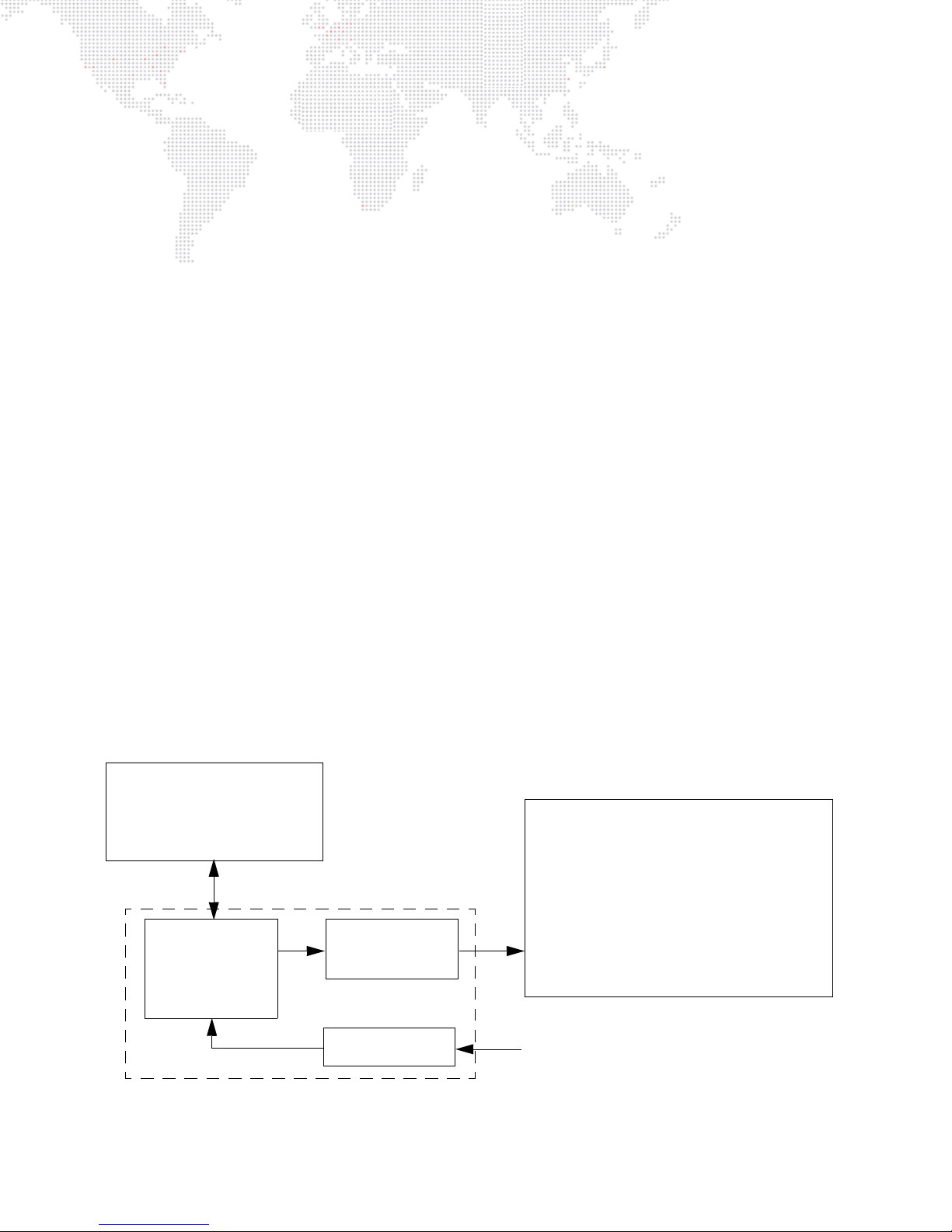
Concepts of Operation
CONSOLE
MAC COMPUTER
DUAL I/O MODULE
FINAL MEDIA OUTPUT
Mbox Extreme MEDIA SERVER
(stored media)
(interface)
(to projector, LED wall, plasma screen, etc.)
AUXILIARY PANEL
(other signals)
Audio, MIDI, SMPTE, SDI video, etc.
Basic Function
The basic function of the Mbox Designer software is to control dynamic media - such as movie clips, still images and
3D objects - during a stage show or other performance. The resulting visual imagery is output to a display device such
as a projector, LED wall, plasma screen or low-res LED lighting fixture. Built-in features allow the media to be
manipulated "on the fly" so that changes can be made during the actual performance and immediately projected. This
eliminates the need to modify media clips in advance, which can take considerable time to be re-rendered. Mbox
Designer is like a combination of After Effects, Photoshop, Maya, and Studio Cut Pro which can be used in real-time
to project custom imagery.
Control
Mbox Designer can be controlled by either a lighting console or a personal computer running Mbox Director software.
In either case, the console or computer can be used to configure and control all aspects of the Mbox media content
and playback parameters.
+ Console - Since a lighting console would typically be used in a stage production, this method is a convenient and
logical way to consolidate all stage control elements into a single device. Control protocol options include
DMX512 and Art-Net which can be input from the console to the Mbox Dual I/O module.
+ Mbox Director - Mbox Director is a software application that allows control of an Mbox Media Server from a
personal computer or from the Mbox server’s computer itself.
This manual assumes that a lighting console is being used to control an Mbox Extreme Media Server. The same
concepts apply to any computer running the Mbox Designer software, although some aspects of the hardware may
be different. For instructions on using Mbox Director, refer to the separate Mbox Director User Manual
(02.9800.0002.xx).
Primary Components
The Mbox Extreme Media Server is made up of several different components that work together to achieve the final
result. The three primary components are the Mac computer, Dual I/O module and Auxiliary panel. The media is stored
on the Mac hard drive, while the Dual I/O module provides the interface between the Mac computer and the
projection devices. The Auxiliary panel provides input/output connectors for signals other than video and DMX512/
Art-Net.
The following simplified diagram illustrates how the components work together:
6 MBOX® MEDIA SERVER USER MANUAL
Figure 1-1: Simplified Component Diagram
Page 15
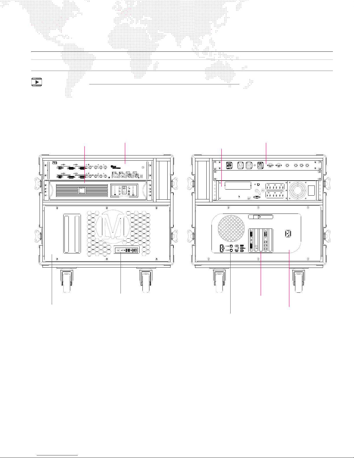
COMPONENTS
SITEWIRING
FAULT
OUTPUT: 120V 50/60Hz
SENSIBILITY
INPUT
RESET
PUSH TO
PROTECTOR
OVERLOAD
USBPORT
2
out
optical
audio
LEFT RIGHT SMPTE IN
MIDIIN MI DIOUT SDI IN R-Y IN B-Y IN
1
in
2 1
(COMPOSITE)
YIN
BALANCED AUDIO OUT
ETHERNET
EDIDC AP TURE
BA
PREVIEW1
SDI1
OUTPU T1
PREVIEWDIM EDID CA PTURE
A
B
Rx
VGA2
DVI2 PREVIEW2
SDI2
STAGEBLACKOUT
VGA1
STAGEBLACKOU T PREVIEWDIM
OUTPU T2
DVI1
RDMTx
INPUT1GENLOCK2 INPUT 2 PORT1 PORT2
BA
ETHERNET
Dual I/O M odule
USB
OUTIN
DMXRx
RDMRx
GENLOCK1
DMX
TM
IN
OUT
USB
COMPU TER
Tx
LINK
MODEL20-9804-0100
POWE R
ACTIVE
ACTIVE
Mac Computer ***
(under faceplate cover)
UPS Power Unit
Dual I/O Module *
Headphone, FireWire,
and USB Connections
Mac
Computer ***
Auxiliary Input Panel **
UPS Power Unit
FRONT VIEW REAR VIEW
Ethernet, Audio, USB,
and FireWire Connections
Graphics, Genlock,
and Capture Cards
Note: This section deals with Mbox Extreme hardware and may not be pertinent to a computer-only installation.
Training Video: Mbox Media Server Training Video Chapter 1: Introduction
Mbox Extreme Case Assembly
The following illustrations show the main case components for the Mbox Extreme v3 hardware:
* Refer to "Dual I/O Module" on page 8.
Figure 1-2: Mbox Extreme v3 Single Rack Unit
** Refer to "Auxiliary Input Panel" on page 10.
*** Refer to "Mac Computer" on page 11.
MBOX® MEDIA SERVER USER MANUAL 7
Page 16
Dual I/O Module
PREVIEW2
A
PREVIEW1
A
STAGEBLACKOUT PREVIEW DIM
TM
SDI 2
B
GENLOCK 2
IN
OUT
ACTIVE
SDI 1
B
PREVIEW DIM
DVI 2
OUTPUT 2
DVI 1
OUTPUT 1
GENLOCK 1
USB
IN
OUT
RDM Rx
RDMT x
DMXRx
INPUT 1
DMX
Dual I/O Module
PORT 2
PORT 1
INPUT 2
ETHERNET
COMPUTER
AB
LINK
Rx
Tx
POWER
ACTIVE USB
MODEL20-9804-0100
EDIDCAPTURE
EDIDCAPTURE
VGA 2
STAGEBLACKOUT
VGA1
Stage
Blackout
Switch
Preview
Dim
Switch
EDID Capture
Switch
LED Indicates
Active Server
LED
Indicates
USB
RGBHV (VGA)
Output to Stage
DVI
Output to
Stage
Preview
(Monitor)
Output
SDI (SD/HD)
Stage Output
Genlock
Input/Output *
DMX512
Inputs
Ethernet (Art-Net) Ports
SDI (SD/HD)
Preview Output
* Only the top set of Genlock connectors (GENLOCK 1) are connected to the Mac computer.
Server
Output 1
Server
Output 2
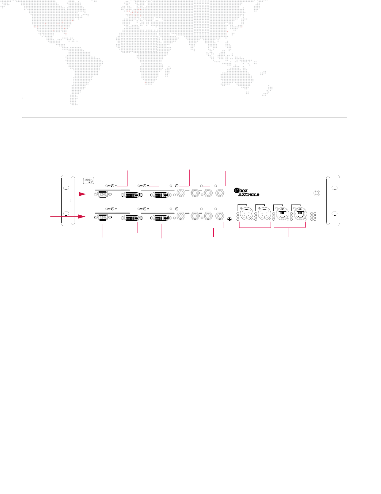
The function of the Dual I/O module is to provide video conversion, final dimming of the video signal, and to send
EDID information to the Mac computer. The module also handles DMX512 and Art-Net input for the computer.
The module functions as a "dual" unit since it provides two independent output sections. These sections are noted in
the drawing below as "Server Output 1" and "Server Output 2."
Note: This is intended to be an overview of the Dual I/O module components. For more information regarding module
operation, refer to "Dual I/O Module" on page 56.
Front Panel Components
Figure 1-3: Mbox Extreme Dual I/O Module (Front View)
Stage Outputs - The module provides three (3) stage outputs: VGA, DVI, and SDI. The intensity level of these stage
outputs can be mastered by the Camera fixture. The stage output may also be suppressed in the case of a system
crash.
Stage Blackout - When this switch is set to "Yes," the stage outputs will be blacked out. When active, the middle
switch causes the preview outputs to dim in parallel with the stage outputs. The right-hand switch controls the EDID
capture functions of the I/O module.
Preview Outputs - The module provides two (2) preview outputs: DVI and SDI. The preview outputs are for local
monitors and are not affected by the hardware dimmer in the Dual I/O module (controlled by the intensity channel on
the Camera fixture).
Preview Dim - When this switch is set to "Yes," the preview will mimic the stage output.
EDID Capture - This switch is used to read and capture data from any EDID (Extended Display Identification Data)
compliant device.
Genlock In/Out - The Genlock ports are used with the Generator Lock function, which syncs all Mbox Extreme
servers in the system so they will begin drawing frames at the same time. Genlock Input and Output connectors are
provided on both output sections, however, only the top pair of Genlock connectors are active. (Note that the Genlock
Out is not a pass-thru. This output should only be used if the Mbox Extreme server is the master for syncing (rather
than using it as a daisy-chain port).
8 MBOX® MEDIA SERVER USER MANUAL
Page 17
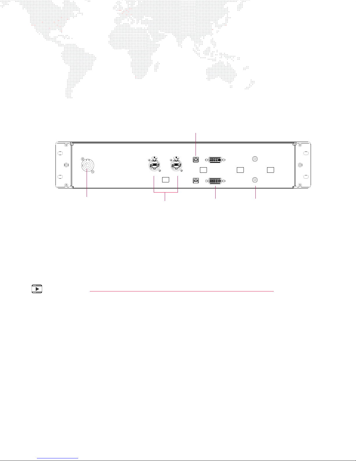
DMX Input Ports - The DMX512 XLR ports are used to receive DMX512 data from an external console or other
USB 1
DVI IN 1
VIDEO SYNC 1
100 -240 VAC
1A MAX
50 / 60 Hz
AC IN
ETHERNET A
USB 2
DVI IN 2
VIDEO SYNC 2
ETHERNET B
Ethernet (Art-Net)
USB Ports (1 & 2)
Video Sync
DVI Inputs
A/C Input Connector
Ports (A & B)
Ports (1 & 2)
(1 & 2)
controller. The left DMX512 port is automatically configured as Art-Net universe 0, while the right DMX512 port is
configured as Art-Net universe 1. (DMX512 cables can only carry one universe of data at a time, and in some cases
the Mbox Designer software requires two universes.)
Ethernet Ports - In general, the two Ethernet ports on the front panel should only be used with Art-Net input from a
control console. If the Mbox Extreme server is receiving DMX512 data, then Ethernet should not be connected to
either of these ports. Since Art-Net has the ability to transmit data for more than one universe at a time, the Ethernet
ports (In & Thru) can be used to daisy-chain multiple Mbox Extreme servers together.
Rear Panel Components
Figure 1-4: Mbox Extreme Dual I/O Module (Rear View)
+ Ethernet - These ports allow Art-Net signals to pass from the I/O module to the Mac computer.
+ USB - These ports allow for control of the I/O module by the Mac computer.
+ DVI Input - These ports receive DVI signals from the Mac computer.
+ Video Sync - These ports allow Genlock signals to pass from the I/O module to the Mac. (Only one of these two
connectors will be connected at a time.)
Training Video: Mbox Media Server Training Video Chapter 2: Hardware Set Up – Front
MBOX® MEDIA SERVER USER MANUAL 9
Page 18
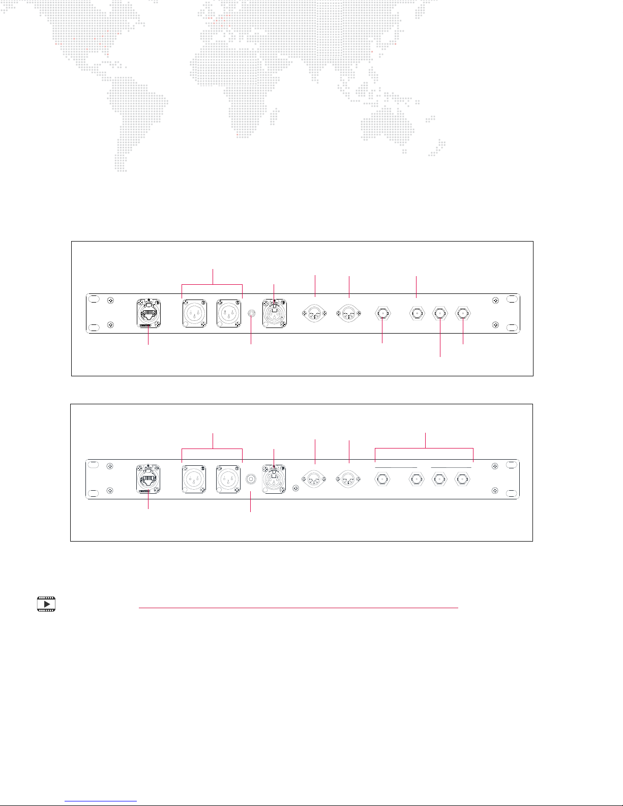
Auxiliary Input Panel
BALANCED AUDIO OUT
RIGHT
MIDI IN
(COMPOSITE)
Y IN
SDI IN R-Y IN B-Y IN
ETHERNET LEFT
MIDI OUT
SMPTE IN
Balanced XLR Audio Out
(Left and Right)
MIDI
In
MIDI
Out
Y Input
(composite)
Ethernet
Port
SMPTE
SDI (SD/HD)
Input
R-Y Input
B-Y Input
Unbalanced Mini Plug Audio Out
(3.5mm Mini Jack)
In
Auxiliary Panel Detail (v3.4)
SDI 1
2 3 4
1
MIDI OUTMIDI IN
SMPTE INRIGHTLEFTETHERNET
BALANCED AUDIO OUT
UNBALANCED
AUDIO OUT
Balanced XLR Audio Out
(Left and Right)
MIDI
In
MIDI
Out
Ethernet
Port
SMPTE
In
Auxiliary Panel Detail (v3.5)
SDI (SD/HD) Inputs
Unbalanced Mini Plug Audio Out
(3.5mm Mini Jack)
The Auxiliary Input panel provides input/output connectors for signals other than video and DMX/Art-Net.
+ Ethernet - This port is used when networking multiple Mbox Extreme servers together.
+ Audio Out - The XLR audio outputs are balanced. The mini plug audio output is unbalanced.
+ SMPTE In - The SMPTE input will accept balanced or unbalanced signals.
+ MIDI In/Out - The MIDI input currently accepts MIDI timecode.
+ SDI Video Inputs - These ports will accept SDI (SD/HD), component, or composite video signals as indicated in
the illustrations below. Note that the v3.5 hardware will only accept SDI (SD/HD).
Figure 1-5: Mbox Extreme Auxiliary Input Panel
Training Video: Mbox Media Server Training Video Chapter 3: Hardware Set Up – Rear
10 MBOX® MEDIA SERVER USER MANUAL
Page 19
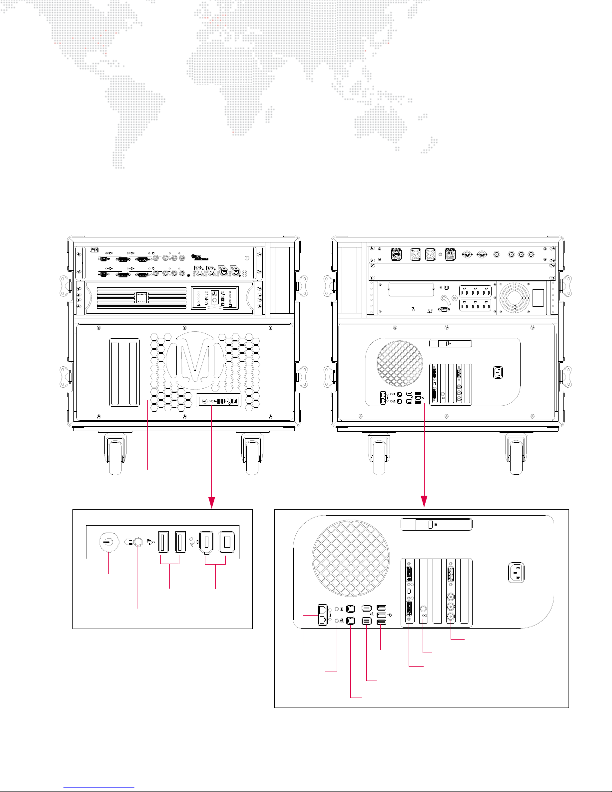
Mac Computer
SITEWIRING
FAULT
OUTPUT: 120V 50/60Hz
SENSIBILITY
INPUT
RESET
PUSH TO
PROTECTOR
OVERLOAD
USBPORT
2
out
optical
audio
LEFT RIGHT SMPTE IN
MIDIIN MI DIOUT SDI IN R-Y IN B-Y IN
1
in
2 1
(COMPOSITE)
YIN
BALANCED AUDIO OUT
ETHERNET
EDIDC AP TURE
BA
PREVIEW1
SDI1
OUTPU T1
PREVIEWDIM EDID CA PTURE
A
B
Rx
VGA2
DVI2 PREVIEW2
SDI2
STAGEBLACKOUT
VGA1
STAGEBLACKOU T PREVIEWDIM
OUTPU T2
DVI1
RDMTx
INPUT1GENLOCK2 INPUT 2 PORT1 PORT2
BA
ETHERNET
Dual I/O M odule
USB
OUTIN
DMXRx
RDMRx
GENLOCK1
DMX
TM
IN
OUT
USB
COMPU TER
Tx
LINK
MODEL20-9804-0100
POWE R
ACTIVE
ACTIVE
2
out
optical
audio
1
in
2 1
Graphics Card
FireWire
SPDIF Audio In/Out
Ethernet
Audio
USB
Genlock Card
Video Capture Card
Mac Rear Detail (v3)
FRONT VIEW REAR VIEW
Mac Front Detail
Power
Button
Headphone Jack
USB
FireWire
CD/DVD ROM (2)
The Mbox Extreme Media Server contains a Mac Pro computer which has been customized by PRG. The Mac
computer is used to operate the Mbox system and store the media. It also provides standard computer connectors
such as USB and FireWire® for the purpose of importing or exporting media data.
+ Hard Drives - The Mac computer contains four hard drives: one which is used to boot the system, and three
which are arranged in a striped raid array (treating them as a single drive). All media files - including the standard
media library and all custom files - are stored on the computer and recalled as needed during a show.
+ Cards - The Mac computer contains a modified Graphics card (which allows for Genlock), a Genlock card, and a
Blackmagic Decklink Video Capture card that can receive an SDI (SD/HD), component, or composite video signal,
and a Sonnet Ethernet card (v3.5 racks only - see details on next page).
Figure 1-6: Mbox Extreme Mac Computer
MBOX® MEDIA SERVER USER MANUAL 11
Page 20
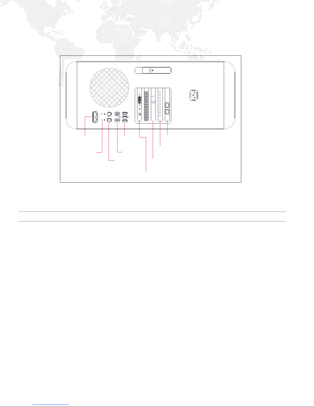
The v3.5 Mbox Extreme rack contains upgraded and new components as shown below:
21
audio
optical
in out
Graphics Card
Genlock Card
Video Capture Card (upgraded in v3.5)
Ethernet Card (v3.5 only)
FireWire
SPDIF
Ethernet
Audio
USB
Audio In/Out
Mac Rear Detail (v3.5)
Figure 1-7: Mbox Extreme v3.5 Components
Note: Version 3.5 racks can be easily identified by the "v3.5" label on the top of the Mbox Extreme rack case.
12 MBOX® MEDIA SERVER USER MANUAL
Page 21
FIXTURE DESCRIPTIONS
DIRECTIONAL
SPOT LIGHT
SPOT LIGHT
DIRECTIONAL
SPOT LIGHT
DIRECTIONAL
3D OBJECT 1
3D OBJECT 2
3D OBJECT 3
3D OBJECT 6
3D OBJECT 5
ORBITY
SPOT LIGHT
DIRECTIONAL
ORBIT
X
AMBIENT
LIGHT
3D OBJECT
3D OBJECT
3D OBJECT
OBJECT
3D
3D OBJECT 4
CAMERA
Note:
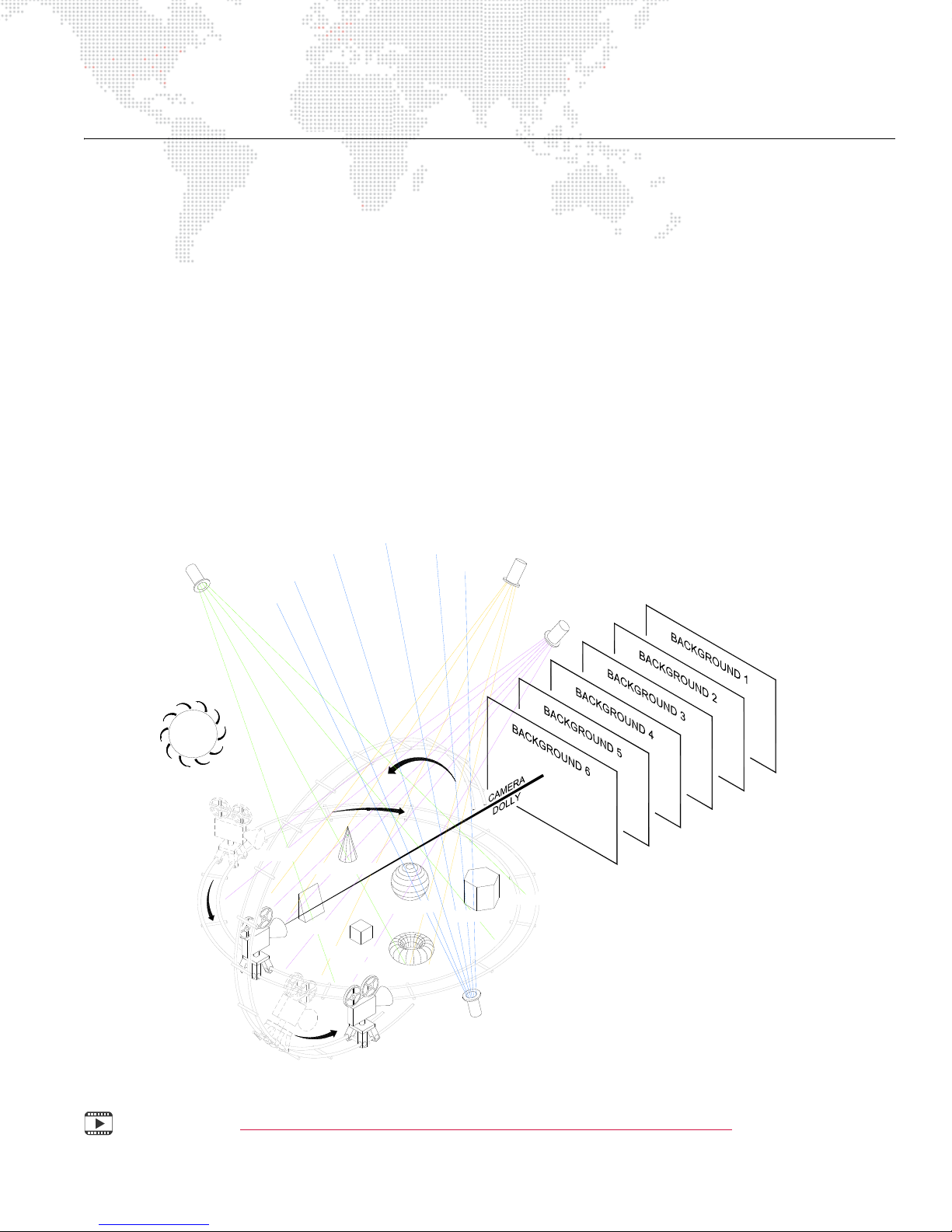
This concept drawing shows six backgrounds
and six 3D objects. The system allows up to 12
active entities at one time. For example, 12
backgrounds; 6 backgrounds and 6 objects; 3
backgrounds and 9 objects; 1 background and 11
objects; etc.
Mbox Environment Concept
In order to get the most from Mbox Designer, it is important to understand the overall concept of the Mbox
environment, which is essentially a building platform for "virtual scenery." The final "look" of this virtual scenery is
comprised of multiple
all of which are controllable elements within the Mbox environment. Likewise, each of these elements has a set of
controllable parameters such as color, texture, size, and rotation. When all combined, it provides an infinite number of
possibilities for the virtual scenery.
At first, the interaction of these elements may seem complicated, but as they are broken down into individual
components, you will find that they are similar to automated lighting parameters which you may already be familiar
with. The only difference is that luminaire parameters coincide with physical hardware - e.g. a motor that controls an
iris - while the Mbox parameters coincide with software elements. For example, just as you would control a luminaire’s
beam color from a console encoder or keypad, you can control the color of an Mbox 3D object.
Once configured, the entire Mbox environment (i.e. the virtual scenery) can be output on any compatible video device
connected to the server.
The following illustration is a virtual representation of each element within the Mbox environment. (More detailed
descriptions of each element are provided on subsequent pages.)
layers
. These layers can be made up of backgrounds, 3D objects, camera angles, and lighting,
Training Video: Mbox Media Server Training Video Chapter 10: Media Server Concepts
Figure 1-8: Mbox 3D Environment
MBOX® MEDIA SERVER USER MANUAL 13
Page 22
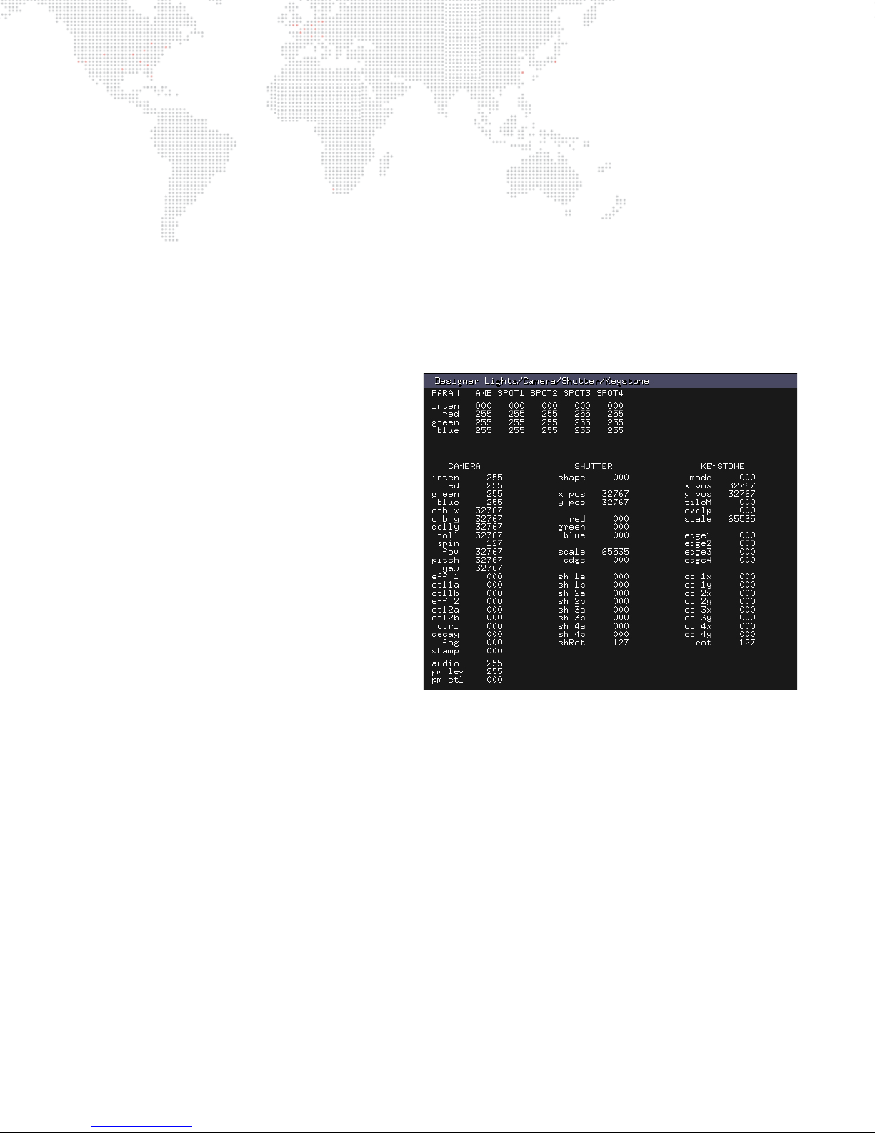
Fixture and Layer Overview
The Mbox environment is based on the concept of
layers
. The system supports up to 12 active layers at a time, each
having its own particular elements and parameters. The elements include a choice of still images, movies, or 3D
objects. The parameters include settings such as opacity, texture, intensity, color, blending, rotation, and many more.
The combination of all 12 layers results in the final "look" of the virtual scenery.
For control purposes, each layer is considered a "fixture" by the console. Some consoles may use one fixture to
control 2D textures and another fixture to control 3D objects. In addition, a set of overall master settings are
considered as yet another fixture. All parameters are controlled by mapping them to control channels on the console.
An appendix at the end of this manual contains tables for all channels used with the Mbox Designer software.
The fixtures and their controllable parameters are outlined below. To help illustrate these concepts, an image of the
corresponding "Heads Up Display" is shown. The HUDs provide feedback regarding the values (VAL) assigned to the
parameters (PARAM). The HUDs will be covered in more detail later in this manual.
MASTER
+ Fixtures: Lights (Ambient, Spotlights 1-4)
- Intensity
- Color: Red, Green, Blue
+ Fixture: Camera
- Intensity
- Master Color: Red, Green, Blue
- Orbit X and Y
- Dolly
- Roll (Spin)
- Field of View
- Pitch
- Yaw
- Effect 1 with Controls A & B
- Effect 2 with Controls A & B
- HUD Control
- Decay
- Fog
- Shutter Damping
- Audio Output Level
- Pixel-Mapping Output Level
- Pixel-Mapping Control
+ Fixture: Shutter (Framing)
- Shape
- X and Y Positions
- Color: Red, Green, Blue
- Scale
- Edge Blending
- Shutter Controls 1a - 4b
- Rotation
+ Fixture: Keystone
- Enable
- X and Y Positions
- Tiling (with Overlap control)
- Edge Blending
- Keystone Controls 1x - 4y
- Rotation
14 MBOX® MEDIA SERVER USER MANUAL
Page 23
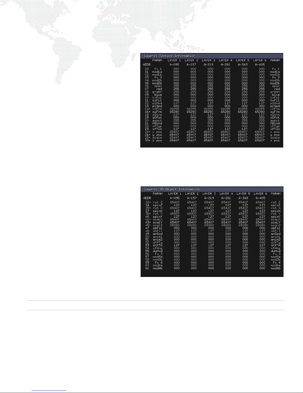
LAYERS
Fixture: Textu re (2 D )
+ Effect 1 with Controls A & B
+ Effect 2 with Controls A & B
+ (Opacity
+ Color: Red, Green, Blue
+ Texture Folder Number
+ Texture File Number
+ Playmode and Playspeed
+ In-Frame
+ Out-Frame
+ Sync Stream and Sync Offset
(Timecode and Layer-to-Layer)
+ Aspect Ratio
+ Frame Blending
+ Crossfade Type and Timing
+ X, Y, and Z Positions
+ Scale
Fixture: Objects (3D)
+ X, Y, Z Rotation, Spin, and Scale
+ Object Folder Number
+ Object File Number
+ Animation Speed
+ Animation 1 and 2
+ Crossfade Type and Timing
+ Drawmode / Layer Blend Mode
+ 3D Effect 1 with Controls A & B
+ 3D Effect 2 with Controls A & B
For a complete parameter maps, refer to "Parameter Mapping" on page 205.
MBOX® MEDIA SERVER USER MANUAL 15
Page 24

Fixture, Layer and Parameter Details
Ambient Light and Spot Lights 1 - 4
The Ambient and Spotlight fixtures are used to light 3D objects or digital gobos and have no effect upon textures used
as backgrounds. Each lighting fixture has an intensity parameter along with color controls for red, green and blue.
Guidelines:
+ If no lights are turned on (i.e., have an intensity level above 0), then the 3D objects will not be visible on the screen.
Camera
The Camera fixture is primarily used to adjust the perspective view of 3D objects. Control options include orbit, dolly,
roll, spin, field of view, pitch, and yaw. The Camera’s secondary function is to provide mastering controls for the final
output color, intensity, pixel-mapping intensity and control, and audio output volume.
The Camera fixture has overall color mixing and two texture effects that affect the composite image created by the
twelve content layers.
Guidelines:
+ The Camera intensity level must be above 0 to see any output from the stage output connectors on the I/O
module.
+ Textures that are not applied to 3D objects or digital gobos are referred to as
in a fixed positional relationship to the camera. The camera cannot move around them as it can with 3D objects
and digital gobos.
backgrounds
. Backgrounds remain
IMPORTANT! When using the Mbox Dual I/O Module, the Camera fixture intensity controls the built-in hardware
dimmer on the I/O module. If this channel is at 0, there will be no visible output from the I/O module’s stage outputs –
though there will be output on the module’s preview outputs.
Shutter Control
Mbox has shutters, much like a Leko, which can be used to mask off areas of the final image. The shutters can be
thought of as sitting in between the camera and the layers. They do not affect any one layer or group of layers, only
the final image. Shutters can be positioned, scaled, rotated, colored, and softened.
Guidelines:
+ The first channel of the Shutter fixture (mode) controls the mode/shape of the shutters; it must be set to a value
other than default to activate the shutters.
+ Each shutter has two channels of control for its position/angle. These channels operate differently depending on
the chosen shutter mode: two depth controls in moving light mode, or depth and angle controls in Leko mode.
Keystone Control
The Keystone fixture allows the final output image to be "straightened up" (i.e., squared) in case it is being projected
onto a surface with an irregular angle. This is accomplished by controlling geometrical keystone adjustments, edge
blending, and tiling. To allow precise keystone corrections, there are individual X and Y controls for each corner of the
output. Scale, rotation and overall X/Y position controls allow further manipulation of the keystone frame.
If using arrayed display devices to create one larger image, Mbox can assist with edge blending and tiling. There are
four independent edge blend controls and three blending curves that may be selected: steep, medium, and shallow.
The tile mode, tile scale, and tile overlap controls allow it to automatically subdivide or "tile" a single image to play on
multiple display devices. With the tile mode control it is possible to select a 2 x 2, 3 x 3, or 4 x 4 array and the grid
position within that array which corresponds to the desired position for each server’s output. To help in creating the
best edge blend between servers, the tile scale and overlap controls allow control of how large the image is and the
overlap between each server’s output.
16 MBOX® MEDIA SERVER USER MANUAL
Page 25
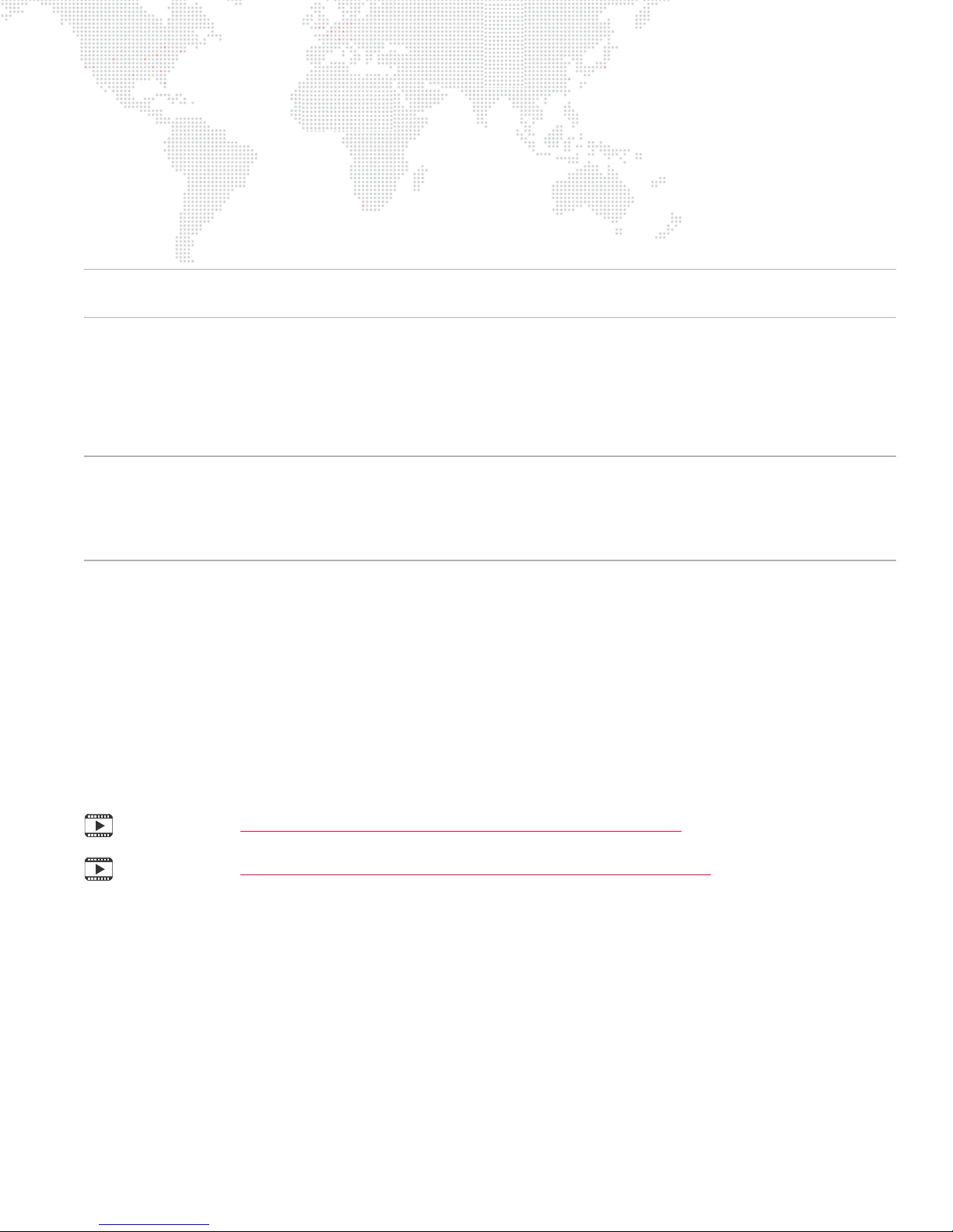
Guidelines:
+ The keystone adjustments act upon the composite image created by the 12 content layers.
Layers: Texture + Object
Each of the 12 content layers incorporates both Texture (2D) and Object (3D) functionality. The Texture element
displays still images and movies as backgrounds. The Object element displays 3D objects or digital gobos. The
combination of the Texture and Object elements make up the final composition of each layer.
CAUTION! Even if you are not actively using 3D objects or digital gobos, there are object-related controls on each
layer that can affect a background texture on that layer (e.g. X & Y Scale, Z Rotation).
Texture
In addition to texture selection, the Texture controls allow further manipulation of each layer. For the most part, the
Texture controls act in 2D space. Each layer can be colored individually; the position, aspect ratio, and scale can be
changed; the playback mode, rate, in/out points, and frame blending can be controlled; the transition type and timing
can be modified; and effects can be applied.
IMPORTANT! Mbox can transition from one texture to another on the same layer. This feature makes Mbox both
powerful and easy to use. The ability to transition on the same layer speeds up programming and can help in live
situations. A transition style (e.g. dissolves, wipes, bleeds) and a time for the Texture transition can be set on each
layer. If a layer’s transition time control is set above 0, Mbox will use the layer’s current transition mode to change from
one image to the next in the time designated.
Object
The Object controls allow selection and manipulation of 3D objects and digital gobos. The controls allow further
manipulation of the layer in 3D space, as well as, control over transitions and effects within the 3D environment. The
Object controls include: scaling on all three axes; rotations and spins on all three axes; object transitions (on the same
layer), transition rotation, and transition timing; control over animated gobos.
Effects
Unlike previous versions of the Mbox software, Mbox Designer has a total of four effects per layer. These effects are a
combination of both Texture and Object effect. There are over 100 Texture effects and 15 Object effects that can be
used in any combination on the layer. Each effect has up to two modifying controls.
Training Video: Mbox Media Server Training Video Chapter 18: 3D Functionality
Training Video: Mbox Media Server Training Video Chapter 19: Shutters & Keystone
MBOX® MEDIA SERVER USER MANUAL 17
Page 26
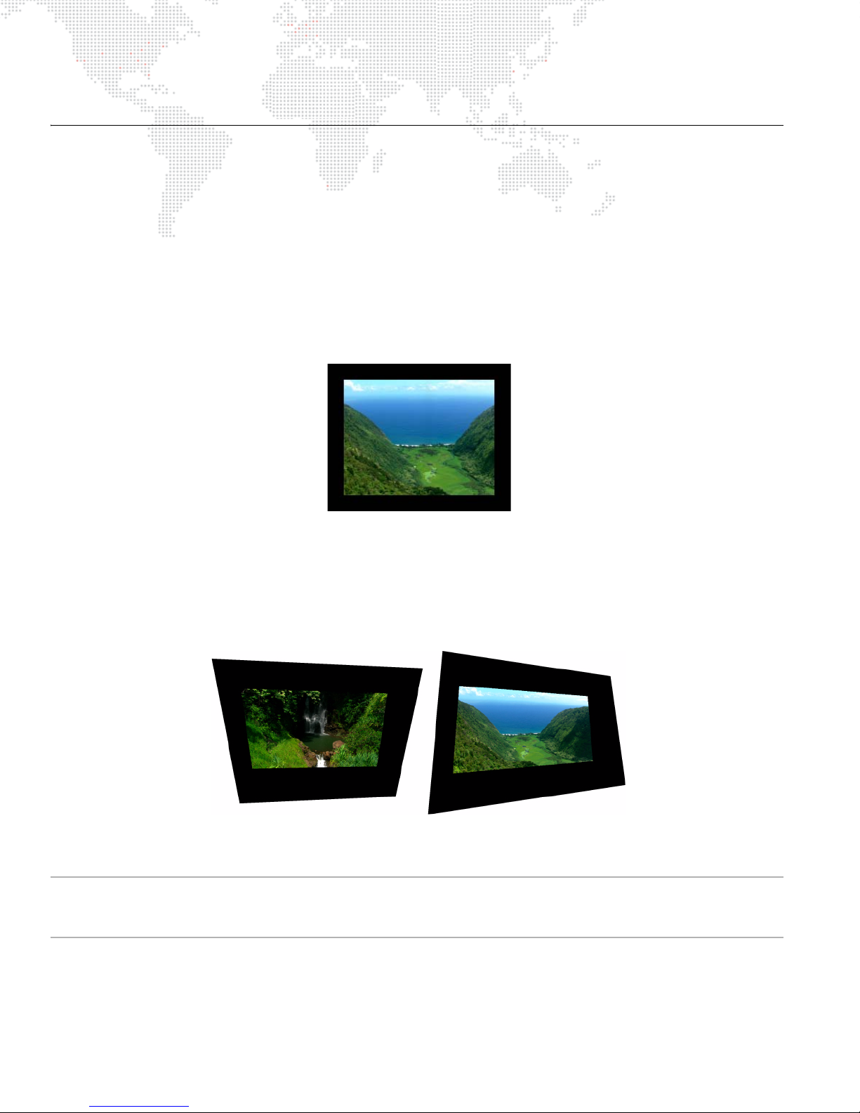
OPERATING MODES
Layers 1-6 Layers 7-12
Mbox Designer v3.7 Modes
Mbox Designer v3.7 has four modes of operation: Single Output, Dual Independent, Panoramic Wide and Panoramic
Dual. The primary purpose of the operating modes is to configure the screen arrangement and required Art-Net
universes.
The Mbox Setup tab, covered later in this manual, is used to change the operating mode. (Refer to "Setup" on
page 46). The four modes function as follows:
Single Output Mode
The Single Output mode provides one video output from the software. (This is the most common mode of operation.)
The output has one set of lighting, camera, shutter, and keystone fixtures. It can display up to 12 content layers.
Figure 1-9: Example of Single Output Mode
Dual Independent Mode
The Dual Independent mode provides two video outputs from the software. The two outputs function as two
independent display surfaces. Each output has its own set of lighting, camera, shutter, and keystone fixtures. Each
output can display up to 6 content layers (for a total of 12).
Figure 1-10: Example of Dual Independent Mode
CAUTION! When using Dual Independent mode with the Dual I/O Module, if Camera 1 dims the first screen and
Camera 2 dims the second screen, then the output sections are reversed. Refer to "Setup: I/O Module" on page 52 to
correct this.
18 MBOX® MEDIA SERVER USER MANUAL
Page 27
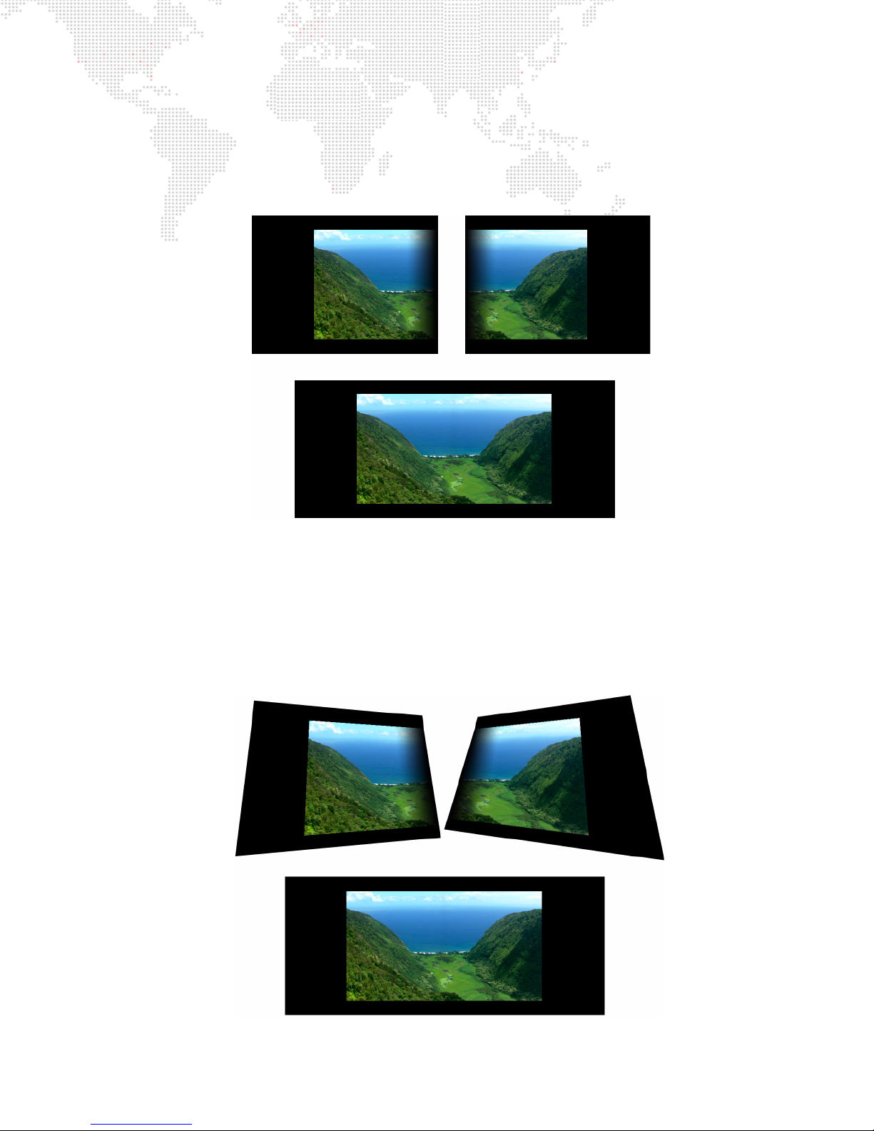
Panoramic Wide Mode
The Panoramic Wide mode provides two video outputs from the software. The two outputs create a single display
surface and the overlap and blending between the two outputs can be adjusted. Outputs can be arranged either
horizontally or vertically. The two outputs share one set of lighting, camera, shutter, and keystone fixtures. Any of the
software's 12 possible content layers can be displayed on either screen or across the overlap with a portion on each
screen.
Figure 1-11: Example of Panoramic Wide Mode
Panoramic Dual Mode
The Panoramic Dual mode provides two video outputs from the software. The two outputs create two cooperative
display surfaces. The outputs have separate geometrical correction and the overlap and blending between the two
outputs can be adjusted. Outputs can be arranged either horizontally or vertically. The two outputs share one set of
lighting and camera fixtures, but each output has its own shutter and keystone fixtures. Any of the software’s 12
possible content layers can be displayed on either screen or with a portion on each screen (with or without an
overlap).
Figure 1-12: Example of Panoramic Dual Mode
MBOX® MEDIA SERVER USER MANUAL 19
Page 28

Notes
20 MBOX® MEDIA SERVER USER MANUAL
Page 29

2.
INSTALLATION AND POWER-UP
This chapter provides instructions for setting up the Mbox server and powering up for the first time.
+
SAMPLE CONFIGURATION DIAGRAMS
+ SETUP
+ GETTING STARTED
+ PATCHING FIXTURES
Page 30
SAMPLE CONFIGURATION DIAGRAMS
SDI
PROJECTOR
DMX IN
VIDEO OUT
PREVIEW
PROJECTOR
FRONT VIEW
REAR VIEW
DMXCONSOLE
2
in out
VIDEO OUT SDI
VIDEO OUT
MONITOR
PREVIEW
MONITOR
VIDEO OUT
VIDEO CAMERA
VIDEO IN
optical
12
in out
audio
1
Overview
There are many possible configurations for setting up single or multiple Mbox Extreme servers. The following
illustrations show just a few of the many possibilities. While the example details the use of the Mbox Extreme server
rack and its included Dual I/O Module, the same examples can be applied to a computer running the Mbox Designer
software.
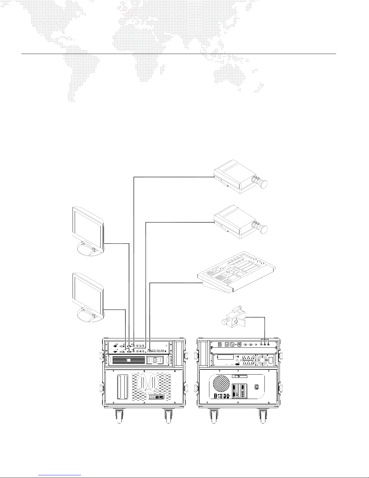
DMX512 Input Configuration: Single Media Server with DMX512 Devices
In the following configuration, DMX512 control signal is distributed from one DMX512 console to multiple DMX512
devices and one Mbox Extreme server. Data is then distributed from the Mbox Extreme server to the other
components as shown below.
Figure 2-1: Single Media Server with DMX512 Devices
22 MBOX® MEDIA SERVER USER MANUAL
Page 31
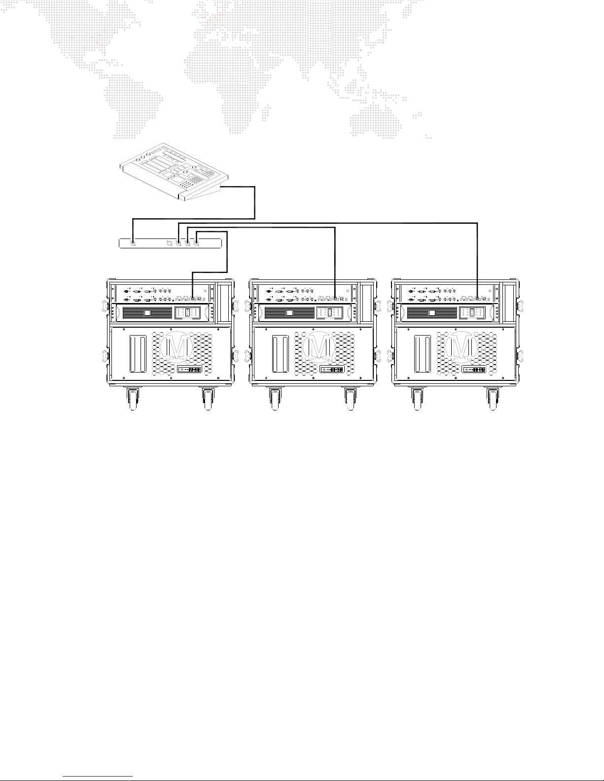
Art-Net Input Configuration: Network Switch and Multiple Media Servers
MBOX EXTREME MBOX EXTREME
DMX CONSOLE
NETWORK SWITCH
Art-Net
IN
MBOX EXTREME
IN IN
In the following configuration, Art-Net control signal is distributed from one control console to one network switch.
The network switch then distributes the control signal to all Mbox Extreme servers.
Figure 2-2: Network Switch and Multiple Media Servers
MBOX® MEDIA SERVER USER MANUAL 23
Page 32
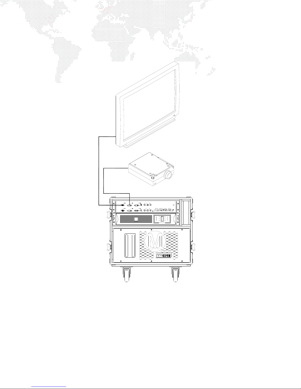
Output Configuration: Single Media Server with Plasma Display and LCD Projector
VGA IN
PLASMA
DISPLAY
DVI 1 OUT
LCD PROJECTOR
MBOX EXTREME
In the following configuration, a Plasma Display and LCD Projector are connected to a single Mbox Extreme server.
24 MBOX® MEDIA SERVER USER MANUAL
Figure 2-3: Single Media Server with Plasma Display and LCD Projector
Page 33
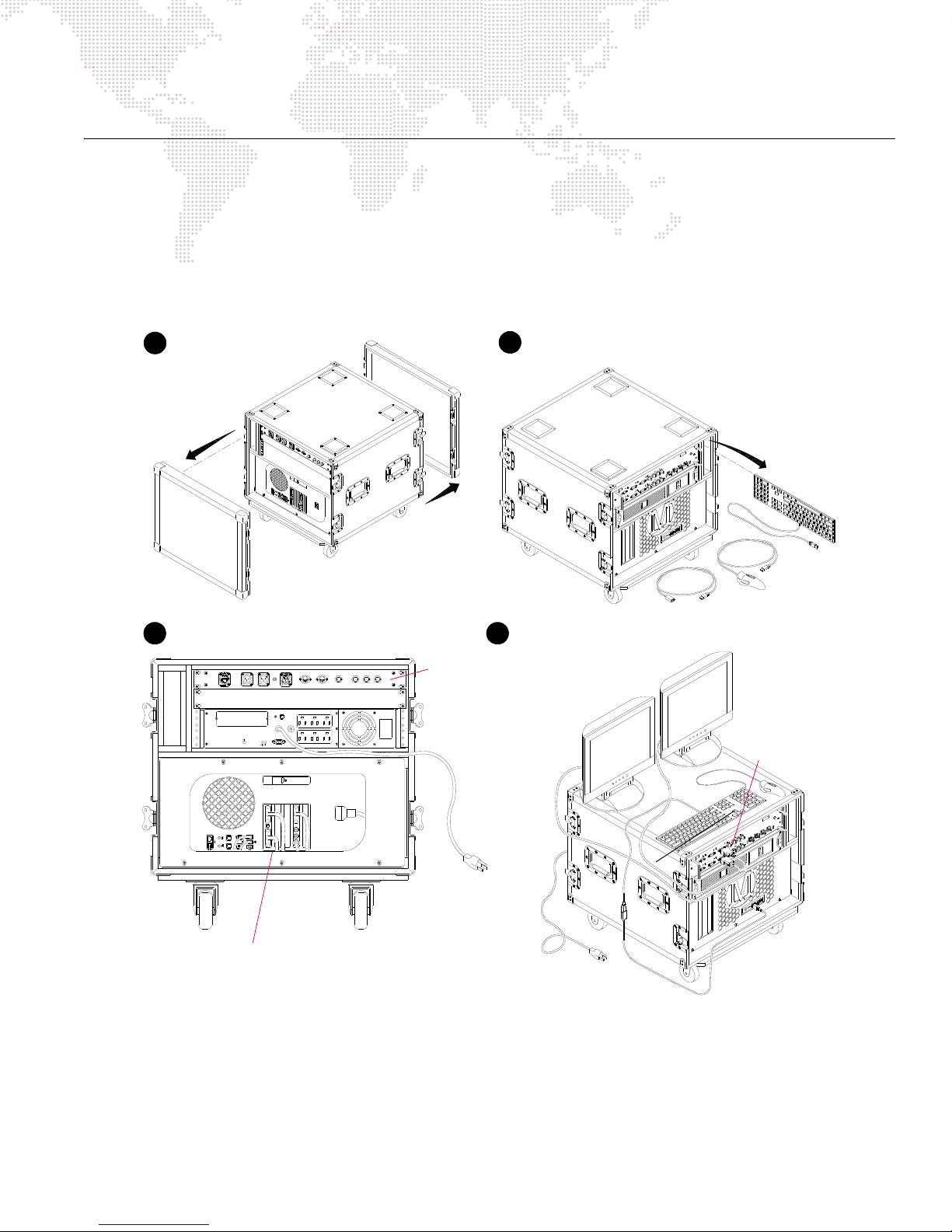
SITEWIRING
FAULT
OUTPUT:120V 50/60Hz
SENSIBILITY
INPUT
RESET
PUSHTO
PROTECTOR
OVERLOAD
USBPORT
(COMPOSITE)
YIN
BALANCED AUDIOOUT
ETHERNET LEFT RIGHT SMPTE IN
MIDIIN MIDIOUT SDI IN R- Y IN B - Y IN
Remove covers
1
2
Remove components
Monitor, USB, and Ethernet Connections
Connect monitor
AC cable to UPS
To AC Power
Connect monitor
data cable to DVI
3
Verify rear connections
4
Connect monitor and power source
Preview
(permanently connected - do not alter)
To AC Power
Auxiliary Input
Connections
or local AC
SETUP
Basic Setup and Connections
To interconnect the case components:
Step 1. Remove front and back covers from case (Figure 2-4).
Step 2. Remove keyboard and trackball from case.
Step 3. At rear of case, verify that Monitor (2), USB (3), Ethernet (2), Video In (2) and Power cables are connected to
computer.
Step 4. At front of Dual I/O module, connect local monitor data cable to DVI connector labeled "Preview."
Step 5. Connect local monitor power cable to UPS or to local AC power service.
Step 6. Connect UPS power cable to local AC power service.
Step 7. Connect stage outputs and other Mbox Extreme servers (if required) according to the following sections.
Figure 2-4: Removing Covers and Components
MBOX® MEDIA SERVER USER MANUAL 25
Page 34
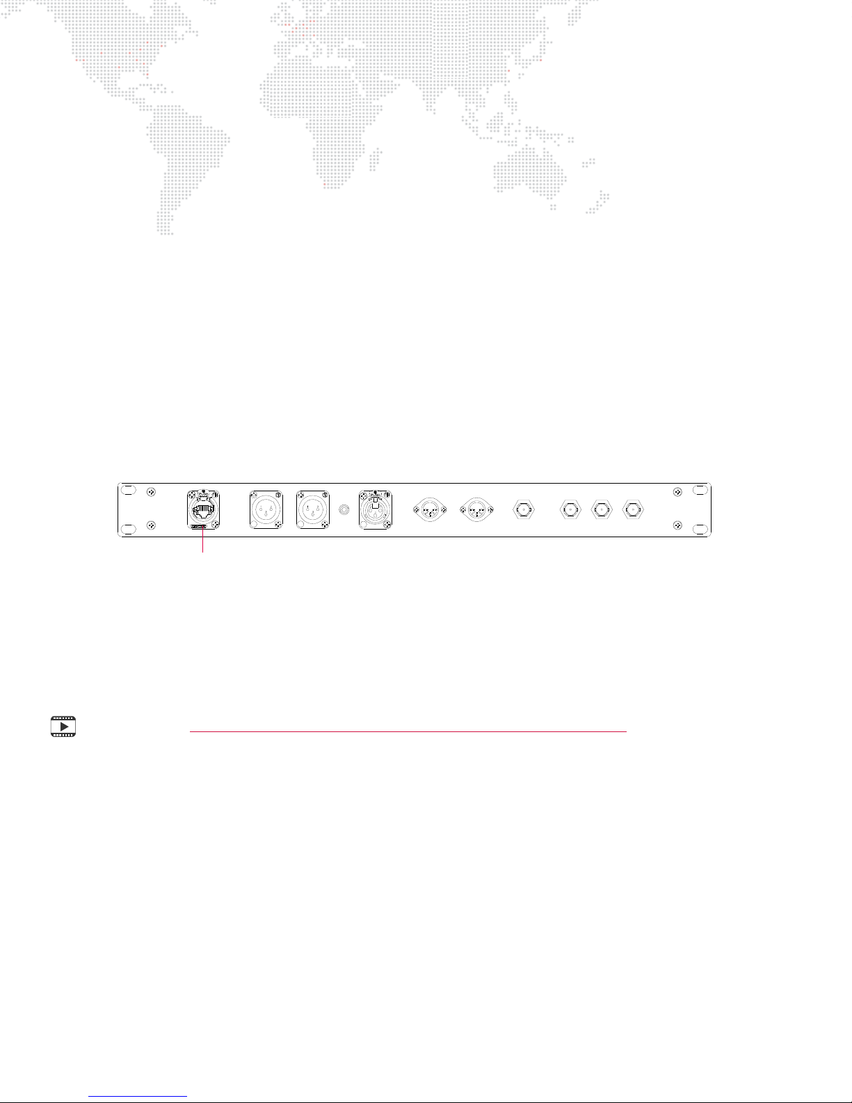
Connecting the Stage Output
BALANCED AUDIO OUT
RIGHT
MIDI IN
(COMPOSITE)
Y IN
SDI IN R-Y IN B-Y IN
ETHERNET LEFT
MIDI OUT
SMPTE IN
Ethernet
Port
The stage output should be connected to one of the outputs ports on the front of Dual I/O module. This will vary
depending on the type of output device. (Refer back to "Dual I/O Module" on page 8.)
Guidelines:
+ Adapters or converters may be required to convert these outputs to specific needs.
+ All DVI connectors on the Dual I/O module are DVI-D (digital only). There is no analog signal present on these
connectors, therefore, a DVI-to-VGA adapter will not work.
Networking Multiple Mbox Extreme Servers
The Mbox Extreme Mac computer has two standard Ethernet ports on its rear panel. The first Ethernet port is preconnected to the two Ethernet ports on the front of the Dual I/O module, and is dedicated to Art-Net reception.
Therefore, this port on the Mac computer and the two ports on the front of the I/O module should NOT be used for
any other purpose.
To network multiple Mbox Extreme servers together for the purpose of content distribution or remote monitoring, use
the Ethernet port located on the Auxiliary Input panel at the rear of the rack (Figure 2-5). The Mac computer’s two
Ethernet ports have preset addressing for this purpose and their settings should not be modified, as changing these
settings may lead to a loss of functionality. Some exceptions do apply; see "Pixel-Mapping" chapter on page 107 for
details.
Figure 2-5: Auxiliary Input Panel (v3.4) *
* The Auxiliary Panel v3.5 only provides SDI (SD/HD) connections. (Refer to "Auxiliary Input Panel" on page 10 .)
The network port is configured in the Mbox Setup tab. Refer to "Setup: Network" on page 51.
Training Video: Mbox Media Server Training Video Chapter 3: Hardware Set Up – Rear
26 MBOX® MEDIA SERVER USER MANUAL
Page 35
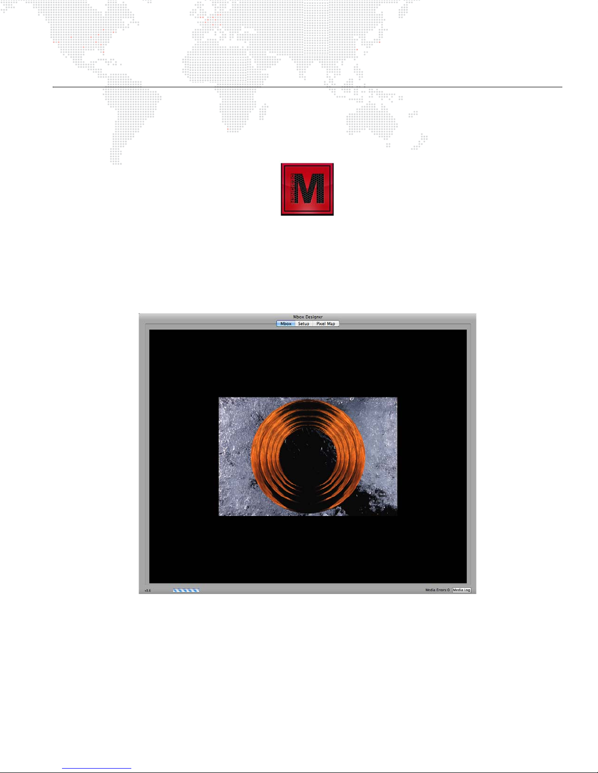
GETTING STARTED
Power-Up Overview
When an Mbox server is powered up, it will typically launch the Mbox Designer application. (If for some reason the
application does not start automatically, locate the Mbox Designer icon on the Apple® dock and click once).
When launched, the Mbox Designer software will initially show a splash screen. After a brief pause, the application
window will appear. During this time the software will scan and index all media. Depending on the preferences, the
software may enter Fullscreen mode. In Fullscreen mode, if no control signal is being received the output screen may
be black.
While in Window mode, the application’s user interface will be shown. This window contains three tabs: Mbox, Setup,
and Pixel Map as shown in this sample screen below:
Upon launch, the Mbox tab will be selected. This tab shows the server’s video output. The Setup tab is used to
configure the server preferences and operating modes, while the Pixel Map tab is used for configuration of the Pixel
Map and its Art-Net output. Refer to "Application Window" on page 45 for more in-depth information about these
functions.
While Mbox Designer is running, there are two important key combinations to note:
+ To toggle between Fullscreen or Window mode, press [ F].
+ To quit Mbox Designer, press [ Q].
MBOX® MEDIA SERVER USER MANUAL 27
Page 36
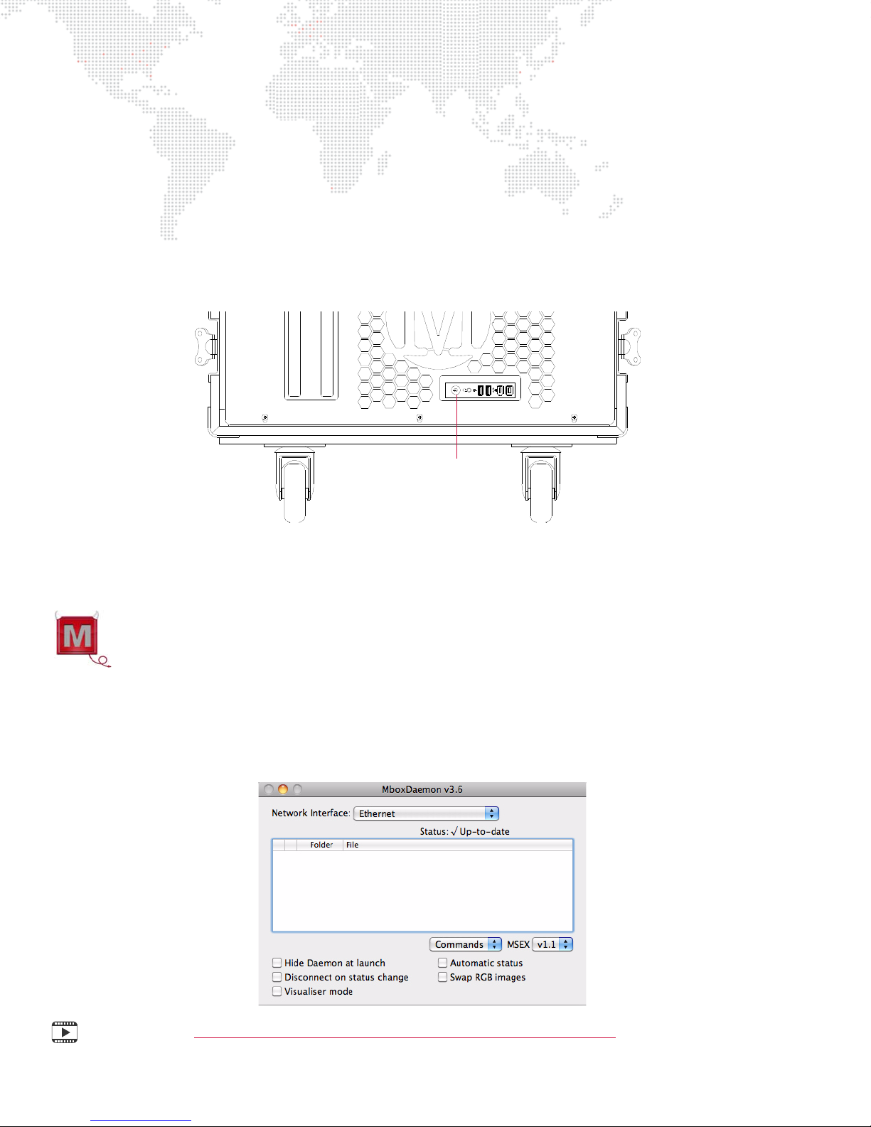
Power-Up Procedure
Power Button
Use the following procedure to power up the Mbox Extreme server.
Step 1. Ensure UPS is powered up.
Step 2. At front of rack, press Mac computer power button (Figure 2-6) and allow computer to boot.
Step 3. Press power button of any connected preview monitors.
Step 4. Allow Mbox DEISGNER software to launch. (The software should start automatically. If it does not start
automatically, click on the icon in the dock. Alternately, locate the application in the Mbox folder and
double-click on it.)
Step 5. Mbox is now ready for operation.
Figure 2-6: Mac Computer Power Button
Mbox Daemon
When the Mbox Designer application is launched, the Mbox Daemon application will also be launched.
This software application is required on all Mbox servers to enable remote feedback. Mbox Daemon may
not be visible, however, since it is a background process. (To force Daemon’s interface to be shown,
press [ D] while the Mbox Designer application is in Window mode, or locate the Daemon icon in the
dock and click on it.)
When viewed, the Mbox Daemon window will always reflect the Network Interface setting as configured in the Mbox
Setup tab. The Network Interface setting can be changed at the Mbox Daemon window, however, this is not
recommended since the setting WILL NOT be retained if Mbox Designer is restarted. A sample Mbox Daemon
window is shown below:
Training Video: Mbox Media Server Training Video Chapter 7: Daemon Application
28 MBOX® MEDIA SERVER USER MANUAL
Page 37

PATCHING FIXTURES
Patching Overview
In order to control Mbox, it will need to be "patched" to a control console. Patching allows channels to be mapped to
the controllable elements of the Mbox environment. Use the following guidelines when patching:
+ One Mbox server running Mbox Designer v3.7 software requires at least 466 DMX512 channels.
+ At least one DMX512 universe per server is required for Single Output, Panoramic Wide, and Panoramic Dual
modes. (Refer to "Operating Modes" on page 18 for more information.)
+ At least two DMX512 universes per server are required for the Dual Independent mode.
+ By default, Mbox is configured to respond to Art-Net universe 0. This allows the server to respond to DMX512
data via the DMX to Art-Net converter built into the Dual I/O module. To control an Mbox server with Art-Net rather
than DMX512, choose a unique Art-Net universe for each server. This setting can be modified on the Setup tab of
the application (refer to "Setup: Control" on page 47).
CAUTION! For ease of operation, the many channels that make up one Mbox server are divided into multiple fixtures.
Unless you are an advanced user, it is strongly recommended that you patch all fixtures that are part of the Mbox
profile. If you do not patch all of the associated fixtures, undesirable results will occur! The chart on the following page
shows all fixtures that make up a single Mbox server. The fixtures must be patched in the order shown.
Layer Guidelines
Mbox Designer allows up to 12 content layers. Use the following guidelines when patching more than six layers:
+ The use of more than six layers requires an additional universe of control data. This additional universe can only
be the next sequential universe to the one that the server is patched to. For example, if the server is patched to
universe 0, the additional layers will be controlled by universe 1. If DMX512 is being used, these two universes
must always be 0 and 1. If Art-Net is being used, any two consecutive universes may be used.
+ When using more than six layers, it is important that the server receive correctly patched data on the second
universe. If this is not done, layers seven and above will not receive appropriate values and will interfere with the
first six layers. Additionally, be sure the server is set to use only six layers if another server is being patched in the
next consecutive universe. The data to control a full server (including lighting fixtures, camera, etc.) will cause
problems if it is on the same universe that another server thinks its extra layers are patched to.
+ Additional layers must always be patched beginning at address 1 on the consecutive universe. The only exception
to this being Dual Independent mode where added layers are patched on the universe that corresponds to each
screen, immediately after the existing layers.
+ Additional layers have all of the functionality of the first six layers. However, the more layers used, the higher the
impact on the performance of the machine.
CAUTION! When using more than six layers, Mbox Designer will require a second Art-Net universe. The number of
layers can be changed at any time - even during a show - however, changing to more than six layers on the fly is not
recommended unless a second universe has already been patched. If this is not the case, strange results may occur.
Training Video: Mbox Media Server Training Video Chapter 4: Patching
MBOX® MEDIA SERVER USER MANUAL 29
Page 38

Parameter Mapping
All 16-bit values are in Big Endian format. For example, the value 23 would be presented as 0 in the first channel and
23 in the second channel.
Start Size Ty pe Universe
1 4 Ambient Light
5 4 Spot Light 1
9 4 Spot Light 2
13 4 Spot Light 3
17 4 Spot Light 4
21 32 Camera Control
53 20 Shutter Control
73 22 Keystone Control
95 62 Layer 1
157 62 Layer 2
219 62 Layer 3
281 62 Layer 4
343 62 Layer 5
405 62 Layer 6
1st
466 Total
Channels
1 62 Layer 7
63 62 Layer 8
125 62 Layer 9
187 62 Layer 10
249 62 Layer 11
311 62 Layer 12
2nd
372 Total
Channels
30 MBOX® MEDIA SERVER USER MANUAL
Page 39
Summary: Dual Output - Panoramic Wide
Summary: Dual Output - Panoramic Dual
Start Size Ty pe Universe
1 4 Ambient Light
5 4 Spot Light 1
9 4 Spot Light 2
13 4 Spot Light 3
17 4 Spot Light 4
21 32 Camera Control
1st
53 20 Shutter Control
73 22 Keystone Control
95 62 Layer 1
466 Total
Channels
157 62 Layer 2
219 62 Layer 3
281 62 Layer 4
343 62 Layer 5
405 62 Layer 6
162 Layer 7
63 62 Layer 8
2nd
125 62 Layer 9
187 62 Layer 10
249 62 Layer 11
372 Total
Channels
311 62 Layer 12
Start Size Ty pe Universe
1 4 Ambient Light
5 4 Spot Light 1
9 4 Spot Light 2
13 4 Spot Light 3
17 4 Spot Light 4
21 32 Camera Control
53 20 Shutter Control 1
1st
73 22 Keystone Control 1
95 20 Shutter Control 2
115 22 Keystone Control 2
508 Total
Channels
137 62 Layer 1
199 62 Layer 2
261 62 Layer 3
323 62 Layer 4
385 62 Layer 5
447 62 Layer 6
162 Layer 7
63 62 Layer 8
2nd
125 62 Layer 9
187 62 Layer 10
249 62 Layer 11
372 Total
Channels
311 62 Layer 12
MBOX® MEDIA SERVER USER MANUAL 31
Page 40

Summary: Dual Output - Independent
(Universe Offset +0)
Summary: Dual Output - Independent
(Universe Offset +1)
Start Size Ty pe
1 4 Ambient Light
5 4 Spot Light 1
9 4 Spot Light 2
13 4 Spot Light 3
17 4 Spot Light 4
21 32 Camera Control
53 20 Shutter Control
73 22 Keystone Control
95 62 Layer 1
157 62 Layer 2
219 62 Layer 3
281 62 Layer 4
343 62 Layer 5
405 62 Layer 6
466 Total Channels
Start Size Ty pe
1 4 Ambient Light
5 4 Spot Light 1
9 4 Spot Light 2
13 4 Spot Light 3
17 4 Spot Light 4
21 32 Camera Control
53 20 Shutter Control
73 22 Keystone Control
95 62 Layer 1
157 62 Layer 2
219 62 Layer 3
281 62 Layer 4
343 62 Layer 5
405 62 Layer 6
466 Total Channels
32 MBOX® MEDIA SERVER USER MANUAL
Page 41
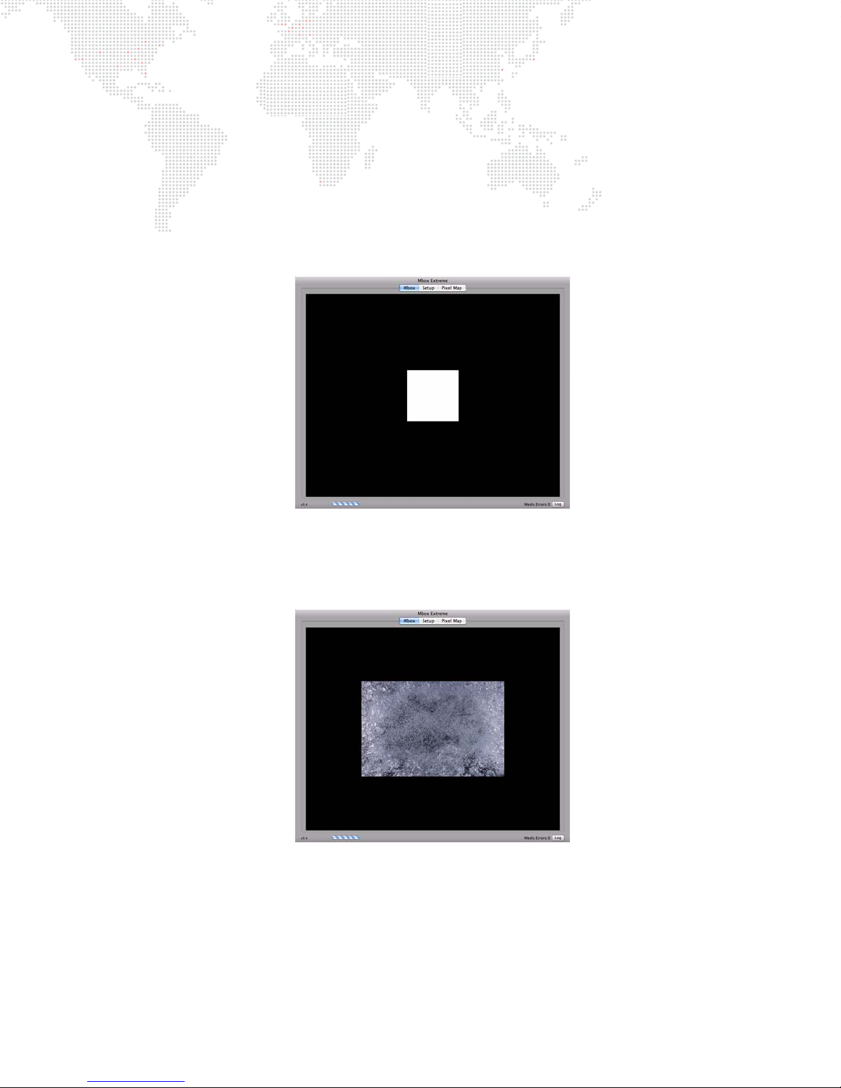
Playing Back Video - Quick Start
Once a console has been connected, the Mbox fixtures patched, and the display device turned on, video can be
played back.
To immediately play back video:
Step 1. At console, select Camera fixture and set its intensity to full. Very Important! – the Camera fixture’s intensity
controls the built-in hardware dimmer on the I/O module. If this channel is at 0, there will be no output from
the stage outputs on the I/O module – though there will be output on the preview outputs.
Step 2. Select Layer 1 fixture and set its opacity to full. A white square should appear in the center of the display:
Step 3. With Layer 1 still selected, set Texture Folder to a value of 1. Then set Texture File to a value of 1. An image
of bubbly water should appear on the display. (The rental Mbox Extreme server comes preloaded with
approximately 1400 content files, if you are running Mbox Designer on your own computer, the content will
be different.)
MBOX® MEDIA SERVER USER MANUAL 33
Page 42
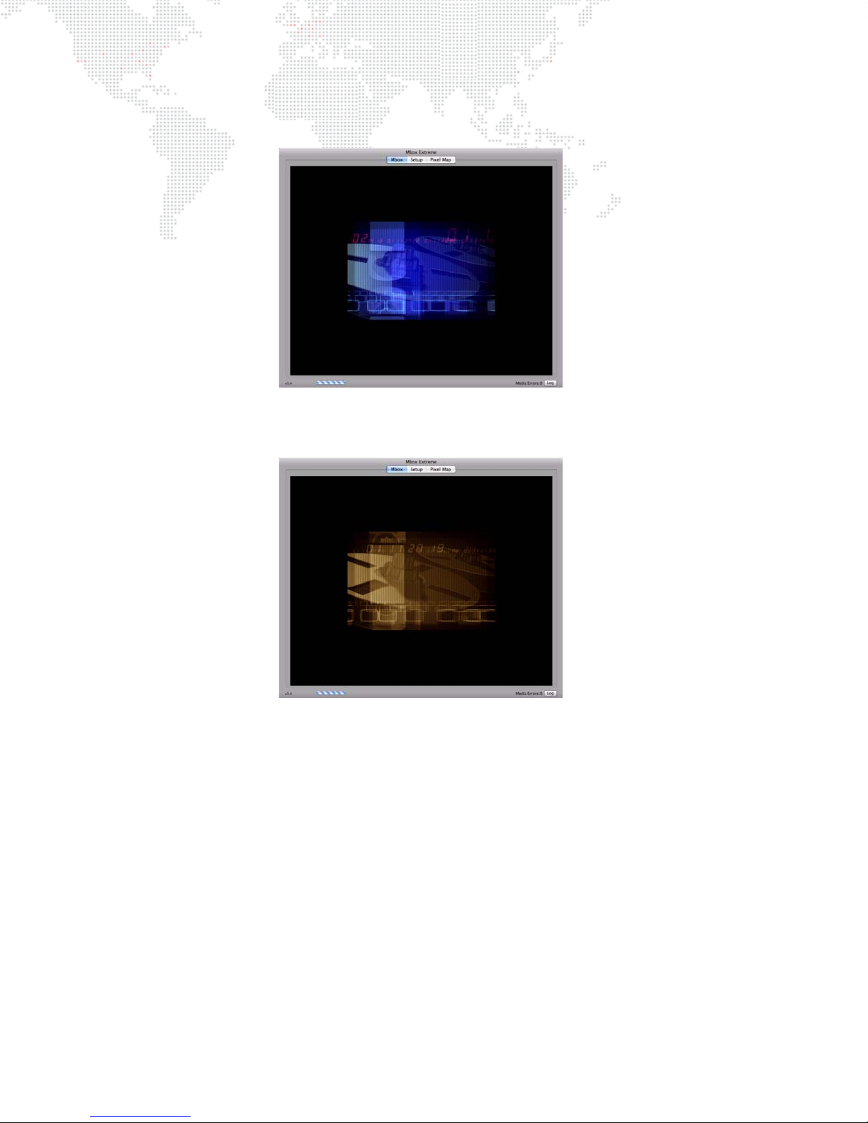
Step 4. At this point, adjust the folder and file parameters to scan the stock media content. For example, changing
to Texture Folder 11,Texture File 1 will result in the following clip:
Step 5. To apply an effect to the layer, for example, set the Effect 1 parameter to 2 (sepia tone) and set the Effect 1
Control A to 255 (full). This should result in a sepia version of the same clip:
34 MBOX® MEDIA SERVER USER MANUAL
Page 43

3.
OPERATION
This chapter provides instructions for configuration and operation of the Mbox server.
+
MEDIA CONTENT
+ APPLICATION WINDOW
+ HEADS UP DISPLAYS (HUDS)
+ DUAL I/O MODULE
+ ENHANCING MBOX PERFORMANCE
Page 44

MEDIA CONTENT
File Type Specifications
The Mbox server supports Apple QuickTime® technology for rendering and playback of images and movie files. The
following file types are supported:
Still Image Files
JPEG (.jpeg or .jpg), PNG (.png), TARGA (.tga), TIFF (.tiff or .tif) for still image files.
+ For still images not requiring transparency, JPEG is the best choice.
+ To use files with transparency, PNG is the best choice.
Movie Files
QuickTime format (.mov) for movie files. Spatial-compressed codecs will always provide better playback results than
temporarily-compressed codecs (e.g. H.264 is not recommended). MP4 is not recommended.
+ Photo JPEG – Medium (50-60%) is the recommended codec for movie clips.
+ Apple ProRes - Light or Normal are recommended, High Quality can be used if you make sure the bitrate is not
too high (150Mb/sec or lower).
Note: ProRes is installed on all rental Mbox servers. But in other cases, unless the ProRes codec is installed on the
computer these files will not play back.
Note: File extensions are not case-sensitive. For example, files with extension .JPG and .jpg are the same.
3D Model Files (Objects)
Custom 3D models can be added to the Mbox server. The server supports the Alias Wavefront™ 3D .obj format.
There are several third-party applications that can export files to this format, including Maya®, Poser®, Bryce®, and
Cheetah3D to name a few.
File extensions for 3D object files:
+ .obj is the standard format.
+ .vle is a PRG proprietary format for encrypted model files.
Additional File Types
Scalable Vector Graphics (svg and svge) for digital gobo files, .aiff for audio files, and .rtf or .txt for text files.
Recommended Practices
JPEG and PNG file types are recommended for creating still image content for optimum output on the Mbox server.
For movie content, Photo-JPEG (60% - 80% quality) is the recommended codec for optimum video playback. Mbox
Designer will play movies that use other QuickTime codecs, if the appropriate codec is installed on the server.
However, sometimes those movies may not load as quickly or play as smoothly as movies that use the preferred
codecs. For best results, all custom content should be created in a single, common format. The Photo-JPEG codec is
strongly recommended. (Refer to "Creating Custom Content" on page 150 for more information.)
Note: In this manual, "preferred movie codecs" refers to Photo-JPEG, DV/DVCPro, Apple Intermediate, Animation,
Apple ProRes 422 (Proxy, Light, Normal and High Quality), and Apple ProRes 4444. All other movie codecs are
considered "non-preferred."
36 MBOX® MEDIA SERVER USER MANUAL
Page 45
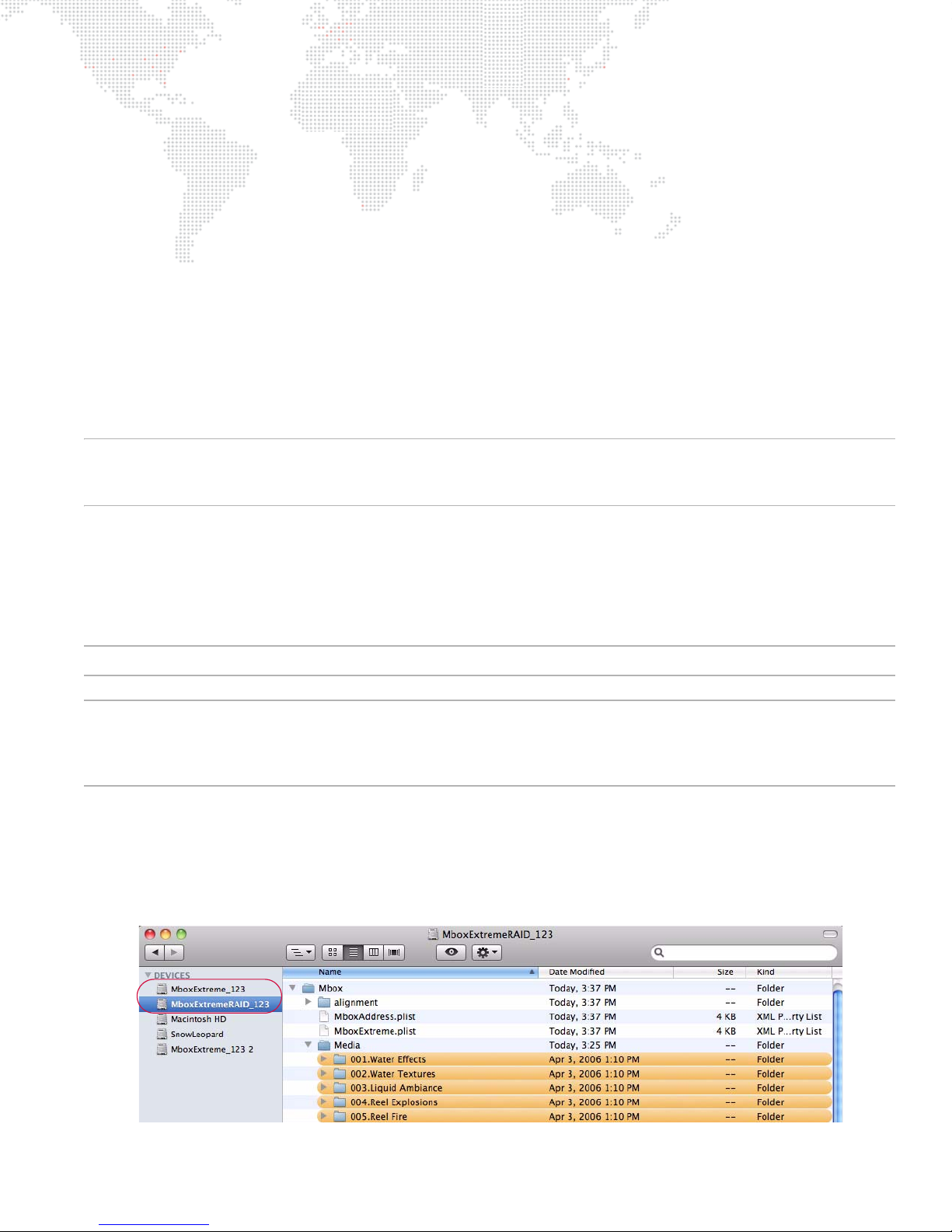
Typically, movie files should not have embedded audio tracks, although embedded audio tracks in movies can be
made to play. To remove audio tracks from movies, use your preferred application to re-render or export the movie
without its audio tracks or try dropping the file onto the Mbox File Converter application, making sure the "copy
audio" checkbox is not checked (see "Mbox File Converter" on page 156).
If the file extension of a DV movie file is changed from .mov to .vid, it will cause Mbox Designer to deinterlace that
movie as it plays. The results of deinterlacing on the fly may not be as good as when using deinterlaced content, but
this feature allows interlaced content to be played without it looking as noticeable. (Refer to "" on page 148 for more
information.)
As is the case with all media servers, the Mbox server playback performance will decrease as both the number of files
playing and the resolution of those media files increases. Content up to and including 1080p (four layers as a
recommended limit) can be played, keeping in mind that extremely large still images may take slightly longer to
appear on screen than smaller files. The amount of compression used when creating a file will also affect
performance. Given equal file resolutions, higher quality (lower compression) files may not play as well as higher
compression (lower quality) files. Depending on the final display device, high-resolution or low-compression files may
not look better than lower-resolution, more highly-compressed files. For best results, try to find a compromise
between quality and performance.
Note: All stock movie and object content on the Mbox server has been copy protected. It will not play on another
computer. If desired, you may lock your own custom content using the Media Lock application, making sure the "copy
audio" checkbox is not checked. (Refer to "Mbox Media Lock" on page 154).
Media Content Management
Mbox provides a flexible media folder structure. Media can reside locally on the Mbox hard-drive or on additional
hard-drives or storage devices connected to the computer. Just be aware that using external devices is not
recommended because playback performance will suffer.
IMPORTANT! The folder paths in this manual are relative., as the actual folder can be in one of several locations.
IMPORTANT! If you are running the Mbox Designer software on your own computer, then the hard-drive and folder
structure may be setup differently to that of the rental Mbox Extreme server. The Mbox folder can be placed on any
drive of the computer, but there must be an alias or symbolic link to the Mbox folder at the root of the boot hard drive
of the computer.
The Mbox server includes four internal hard-drives arranged as follows:
+ Drive 1 (MboxExtreme_xxx) is used to store the operating system (OS) and Mbox Designer application. The
computer boots from this drive.
+ Drives 2-4 (MboxExtremeRAID_xxx) are are striped as RAID-0 and are used to store media content and
preferences.
MBOX® MEDIA SERVER USER MANUAL 37
Page 46
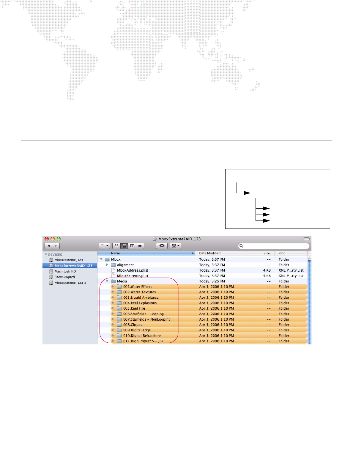
At startup, the Mbox Designer software performs a media scan to search all folders that reside within the
001.videos
001.rain.mov
002.drops.jpg
etc.
MboxExtremeRAID/Mbox/Media
and
Mbox/Models
provided the following guidelines are observed:
+ Aliases must link to folders on the supplemental media. They cannot be aliased to files.
+ An alias cannot refer to another alias.
+ The
Each time the Mbox Designer software completes a media scan, a text file is created with all media files found and
their corresponding combined file numbers. This text file can be found at
Note: The initial media scan allows the locations of files to be resolved at startup, therefore the "distance" of a file
from the main folder has no effect on the time required to find a file. In addition, the content in the
allowed to be nested (folders within folders) to a limit of 64 folders deep.
/Mbox/Media
folders on the Mbox server’s RAID. External media can be attached to these folders using aliases,
, and
/Mbox/Models
folders cannot be aliases.
/Mbox/Media_Report.txt
Media
Mbox/Media
folder is
Folder and File Numbering
Media content files are stored on the RAID hard-drive. They are
arranged into individual "Library" folders within the
Mbox/Models
index value. In turn, each file within the Library folder must be
named using a 3-digit index value between 000 to 255 as a prefix.
Two control channels on the console will be used to select a Library
folder and the numbered file within that folder.
folders. Each folder name must begin with a 3-digit
/Mbox/Media
or
/
Library folders within the
the number by a period or a space. For example:
Files within each library folder must have a numerical prefix, can have a descriptive name if desired, and must have a
three-letter file extension. Each of these parts should be separated by a period:
Movie and still image files may be numbered between 000 and 255 and placed in folders numbered 001 - 254. Models
and digital gobos may be numbered between 000 and 255 and placed in folders numbered 001 - 255.
38 MBOX® MEDIA SERVER USER MANUAL
Media
folder must have a number prefix and can have a descriptive name separated from
025.Central Park or 025 Central Park
001.Great Lawn.jpg or 001.jpg
Page 47
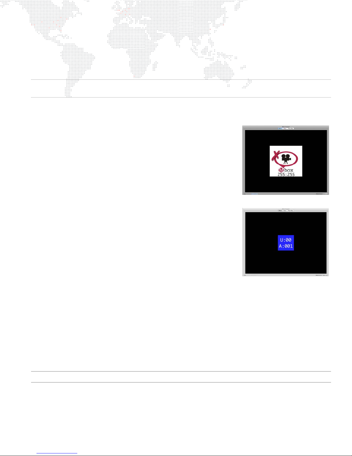
Folder 000 in both the
No Camera
Address
Media
and
Models
folders is reserved and should not be used.
The stock PRG movies and still images are located in Media folders 001 - 038 and 248 - 254. Media folder 255 is
reserved for video inputs and layer copy functionality.
The stock PRG 3D objects, animated gobos, and digital gobo files are located in Model folders 001 - 006.
CAUTION! File names (after the numerical prefix) should not start with numbers, as this confuses the media indexing.
For example, a file name such as 001.427 Hemi Engine.mov is bad, whereas 001.Hemi Engine 427.mov is fine.
Additional Media Content Organization Guidelines
+ Media folders 000 and 255 are reserved for default files and utility files
(text streams, layer copy, video inputs) respectively. Every Mbox server
has a standard video capture card that can receive SDI (SD/HD) video
input. This input can be used to display video from an external source on
any layer, as if it were content on the server's hard-drive. You may also
display video from a USB or FireWire® camera connected directly to the
computer. To view video from the video inputs, select Texture folder 255
and either texture 255, 254, 253, or 252 - the Setup tab allows assignment
of up to four video inputs to these values. If no video capture card or
camera is detected and diagnostics are enabled, it will show the "No
Camera" image on the display when requesting one of these media
locations.
+ When adding content files, DO NOT duplicate existing folder and file
number combinations. It is best to make new folders for custom content.
+ Leading zeros are not required when numbering folders or files, but they
can help by making the file listing easier to read.
+ Folder 255, texture 000 will display Mbox’s Art-Net universe and start
address.
+ Mbox Designer scans for content upon startup. If new content is added
while Mbox Designer is running, the Media and Models folders must be
re-scanned in order to use that new content. These folders can be rescanned while Mbox Designer is running by pressing [ R] on the server's
keyboard or from the console by using the control channel on the Camera
fixture. There will be a brief pause in movie playback while the rescan
takes place.
+ Media Folder 255 contains the following:
0: Mbox patch info
1-30: reserved for Network Stream Inputs
101-108: reserved for Layer Copy FX- functionality for Layers 1-8 respectively
121-128: reserved for Layer Copy FX+ functionality for Layers 1-8 respectively
141-148: reserved for Layer Copy Raw functionality for Layers 1-8 respectively
252-255: reserved for video inputs
Note: Refer to "Layer Copy" on page 82 for more information about the Layer Copy feature.
MBOX® MEDIA SERVER USER MANUAL 39
Page 48
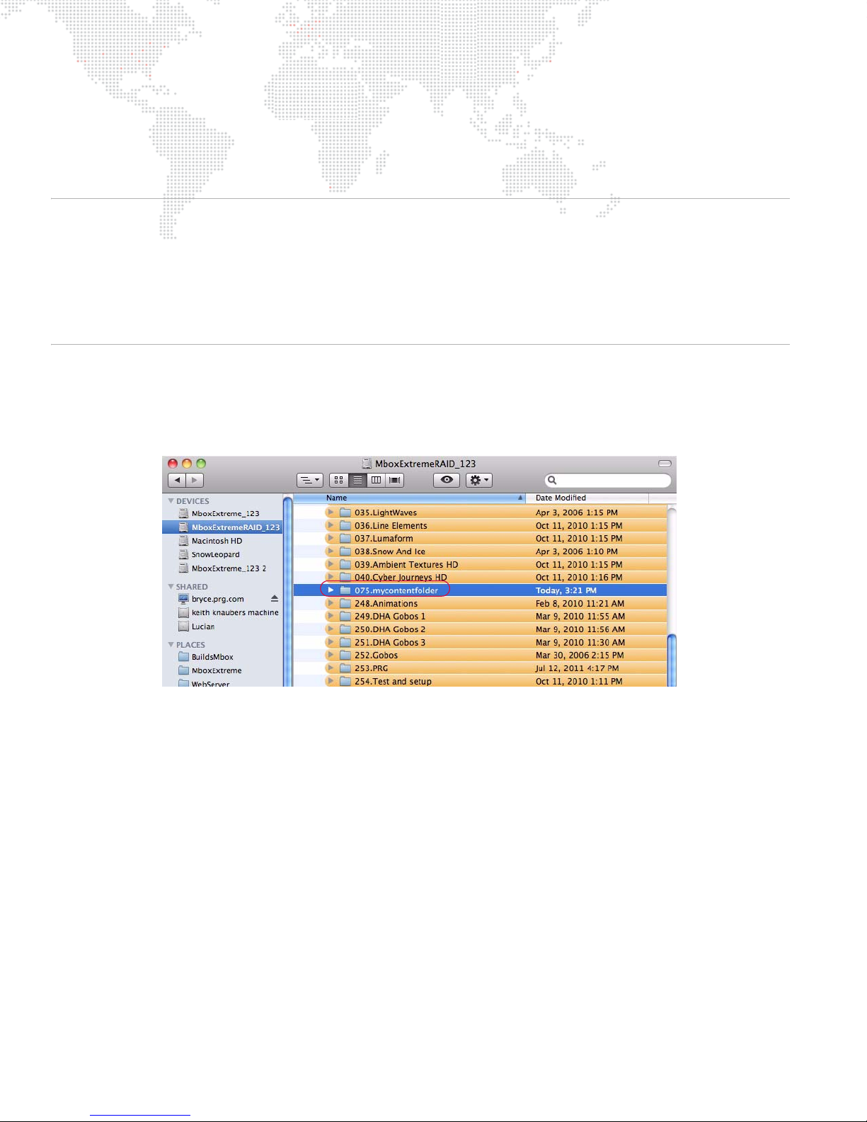
Adding Media Content
When adding content files, it is recommended that new, unique folder numbers be created for the custom content. It
is possible to have more than one folder with the same numerical prefix, however, as long as the content files within
such folders do not have the same numerical prefix.
CAUTION! Numbered content files will be assigned a folder number that is equal to the numerical prefix of their
immediate parent folder. Therefore, using folders without numbers requires caution.
A file at this location:
because the immediate parent of the numbered file has no numerical prefix
The correct method:
folder 022.
To add movies or image files:
Step 1. Open
Step 2. At File menu, select New Folder and enter a unique 3-digit number (that is not already being used) followed
by a descriptive name. For example, "075.mycontentfolder".
Media/022.Water/BlueWater/001.SomeWater.mov
Media/BlueWater/022.Water/001.SomeWater.mov
Mbox/Media
folder.
- will be assumed to be in folder 000,
- would work as desired, assigning the file to
Step 3. Copy image and/or movie files into the new folder.
Step 4. For each file, add a unique 3-digit index value to each file (between 0-255) along with a descriptive name
that includes the file extension. For example, "001.earth.jpg", "002.wind.mov", "003.fire.mov", etc. (Note
the caution given above.)
To add 3D objects:
Step 1. Open
Step 2. At File menu, select New Folder and enter a unique 3-digit number (that is not already being used) followed
Step 3. Copy model files into the new folder.
Step 4. For each file, add a unique 3-digit index value to each file (between 0-255) along with a descriptive name
40 MBOX® MEDIA SERVER USER MANUAL
Mbox/Models
by a descriptive name. For example, "012.mymodels".
that includes the file extension. For example, "001.man.obj", "002.hammer.obj", "003.airplane.obj", etc.
(Note the caution given above.)
folder.
Page 49

Grouped Content
Description
The Mbox applications support the use of "content grouping" in order to allow servers to have content for all servers
stored on their hard-drive, but to allow each server to play only the content desired for its own output(s). In this
manner, content synchronization can ensure that all show content is on all servers (allowing for one server to take over
for another). When programming, selecting a folder and file will cause content (with the matching folder.file index) to
be played from within the server’s corresponding group folder only.
To facilitate keystone, warping, and projection mapping setups, each output of each server can be given a numerical
"Identity" value (between 0 and 255). The Identity property is also used for content group designation. In the content
database indexing system for Mbox, the content group is a prefixed 8-bit value - i.e. Group.Folder.File, which each
element being a number 0 - 255. (This concept essentially extends Mbox's content indexing system to be 24-bit
rather than 16-bit as prior to v3.6 software.)
If content is not assigned a group number, then it will always be played when a particular Folder and File are selected.
Standard rules for file conflicts (repeated Folder.File indices are conflicts) will apply. If content is assigned a group
number, then there may be multiple Folder.File indices with the same values. But since each will have a unique Group
number, there are no conflicts. The playback of content with the matching group index is automatic and no parameter
on the controller (console or Mbox Director) selects this value. Users will preset the Identity of each output of each
server in order to dictate what content is played.
Usage
The typical usage for grouped content will be when more than one Mbox server is used as a portion of a multi-server
(widescreen, matrix, etc.) setup with coordinated outputs. Often these setups will make one larger image with each
server supplying one or two sections of the larger image. The content grouping scheme allows the programmer to
select the same Folder and File values for all servers and get the appropriate portion of the larger image to play on
each server.
Note: Content Grouping does not chop up or distribute content automatically to the relevant server. It merely causes
the server's designated group's content to play when a folder.file is selected.
Usage is not limited to multiple servers making up one larger coordinated raster. Grouped content can be used as a
tool for content organization even when disparate content is used on multiple servers.
Example:
Imagine a system with three servers, each having two outputs in Dual Independent mode. This system has six total
outputs, and for a wide blend, each output will display 1/6th of the total image. For best playback results, the user
may choose to supply six unique pieces of content each being approximately 1/6th of the final image (plus overlap as
required).
Prior to Mbox v3.6 the user could place all six pieces of content into the same folder and give each piece a unique file
number. (e.g. 001.001, 001.002, 001.003 and so on…) When programming the show, the user would have to select six
different pieces of media for playback, a different file on each server.
Now, the user would first designate the Identity number for each output in the system (e.g. 1, 2, 3, 4, 5, and 6). Then
the user would create six different content folders (one for each group identity) on each of the three servers, labeling
them uniquely (see below for details) with numbers to match Group 1, Group 2, Group 3, etc. but each having the
same folder index number. Inside each folder the user would place the content (1/6th of the final content image) that
matches that output's position in the overall scheme. The individual content files that make up one larger image would
all be given the same file index number.
With the identity set in this way the user could then select folder 001 and file 003 for playback on all the servers. The
output designated as Identity 1 would play Group001.Folder001.File003, and so on…
MBOX® MEDIA SERVER USER MANUAL 41
Page 50

Note: Because the panoramic output modes are treated as one larger output when placing and sizing content for
playback on a server's layers, their output is treated as only one content group by the Mbox server. The identity
setting for the server's second output (Output 2) will affect keystone, warp, and projection mapping for that output,
but in panoramic modes, different content will not (and cannot) be selected automatically based on the Identity for
Output 2.
Configuration/Setup
Inside the Mbox/Media and Mbox/Models folders, the actual content folders can be renamed to enable content
grouping. Without content grouping a folder might be called "004.My Movies". With content grouping a user might
have several folders - "[001]004.My Movies", "[002]004.My Movies", [003]004.My Movies" and so on.
The actual text name of the folder does not matter in the indexing system, so for added clarity, the folder could be
called something like "[002]004.My Movies Group 2"
Allowed syntax:
+ [Group #]Folder #.Folder Name -> no space or period between [Group] and Folder
+ [Group #] Folder #.Folder Name -> space between [Group] and Folder
+ [Group #].Folder #.Folder Name -> period between [Group] and Folder
42 MBOX® MEDIA SERVER USER MANUAL
Page 51
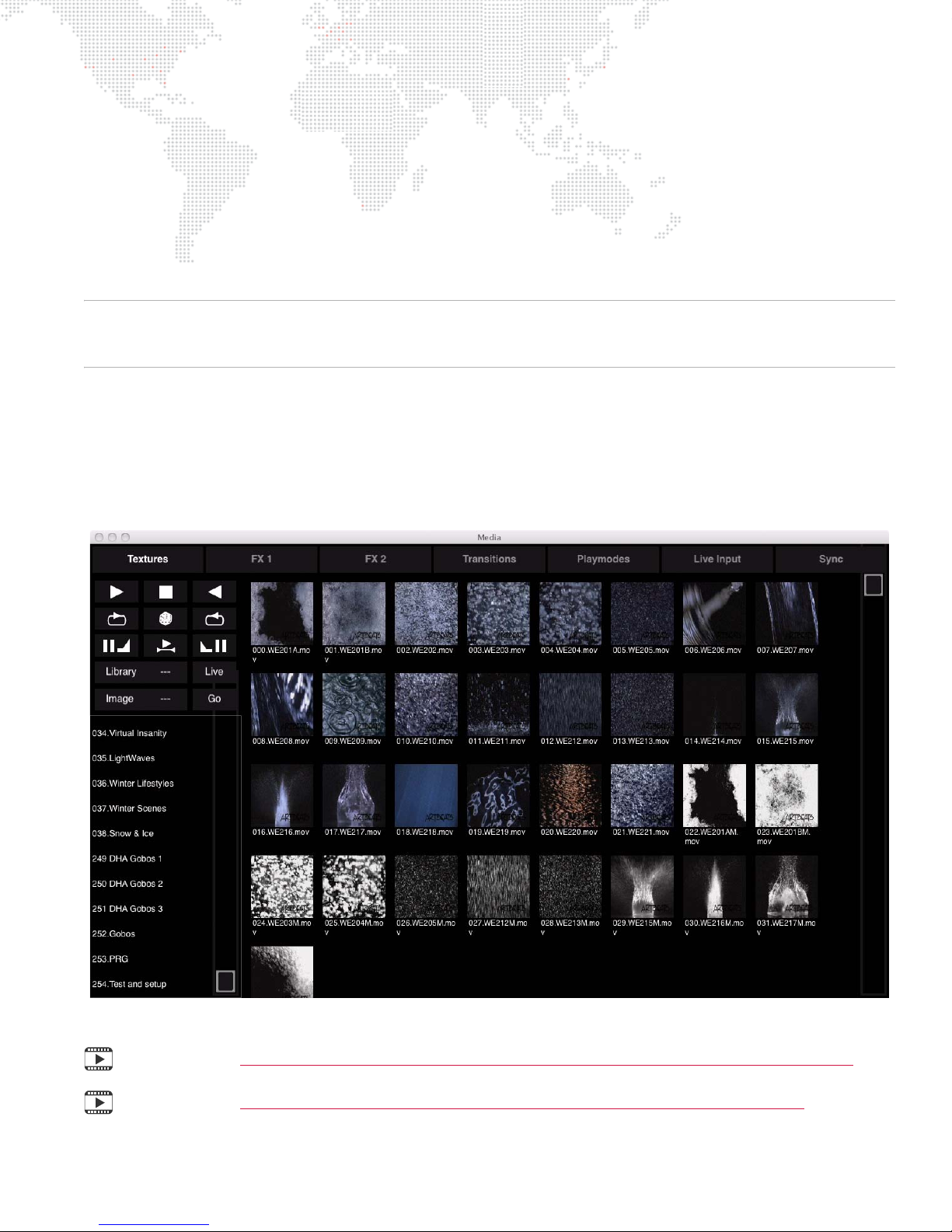
Creating and Viewing Content Thumbnails
The Mbox Designer software will create thumbnail images of the content. To force the creation of new thumbnails in
Mbox Designer, press [ T].
Thumbnail images are stored in a standard location on every server and are grouped with HTML files that allow any
networked computer (Mac or PC) to use an HTML browser to view the thumbnails on the server. Individual thumbnails
can also be used by consoles connected to the server. The thumbnail files are located in folders on each server at
/Library/Application Support/Mbox
in the address line of the browser application.
CAUTION! While thumbnails are being created, playback performance on the server may be severely affected.
Thumbnail creation time will depend on the amount of content in the
being created, you will not be able to view them from either a browser or the Mbox Remote application.
. The HTML pages can be browsed by entering
Media
and
Models
http://IP Address of remote server
folders. While thumbnails are
Console Interface
Once patched to an automated lighting console, the Mbox server can be controlled using the console’s interface. The
following example shows the Media window offered by the PRG Vx76 series console. In this case, the window is
displaying thumbnails for the Texture library media files. Basic controls - such Play, Stop, Rewind, Loop, etc. - are
also available in the window.
Training Video: Mbox Media Server Training Video Chapter 6: CITP – Streaming Feedback & Thumbnails
Training Video: Mbox Media Server Training Video Chapter 20: Codes, Storage, and Media Types
MBOX® MEDIA SERVER USER MANUAL 43
Page 52
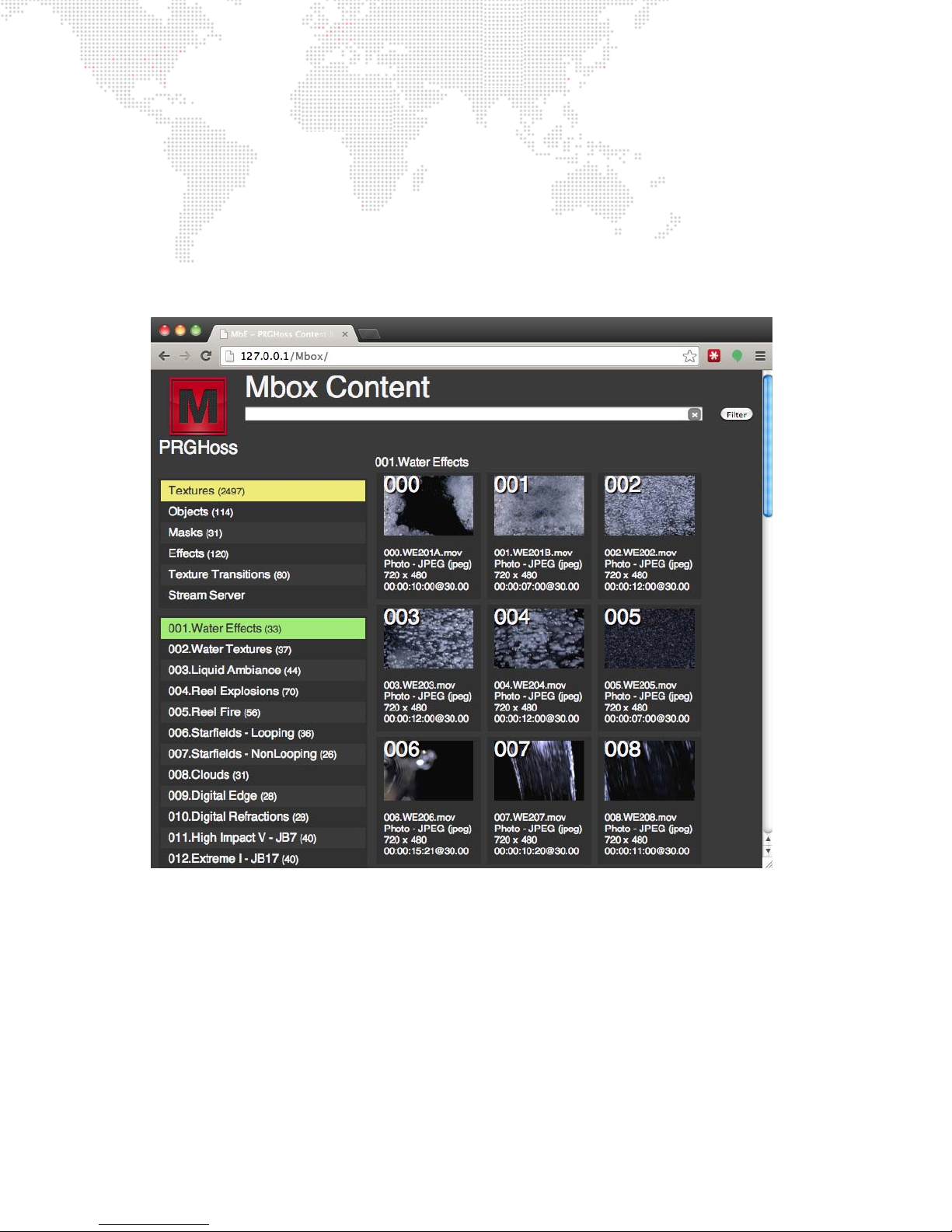
Viewing Thumbnails in a Browser
Another way to view media thumbnails on an Mbox server without a CITP-connected console or Mbox Director, is to
use the web browser of any computer connected to the Mbox network. Enter the following into the browser:
+ If using a browser on the local Mbox sever, the address http://127.0.0.1/Mbox can be used to view the local
thumbnails.
+ To view the thumbnails on a remote machine, enter that machine’s IP address. For example:
http://192.168.0.123/Mbox
When accessing the web pages from a rental Mbox server, the /Mbox portion of the address can be omitted.
44 MBOX® MEDIA SERVER USER MANUAL
Page 53
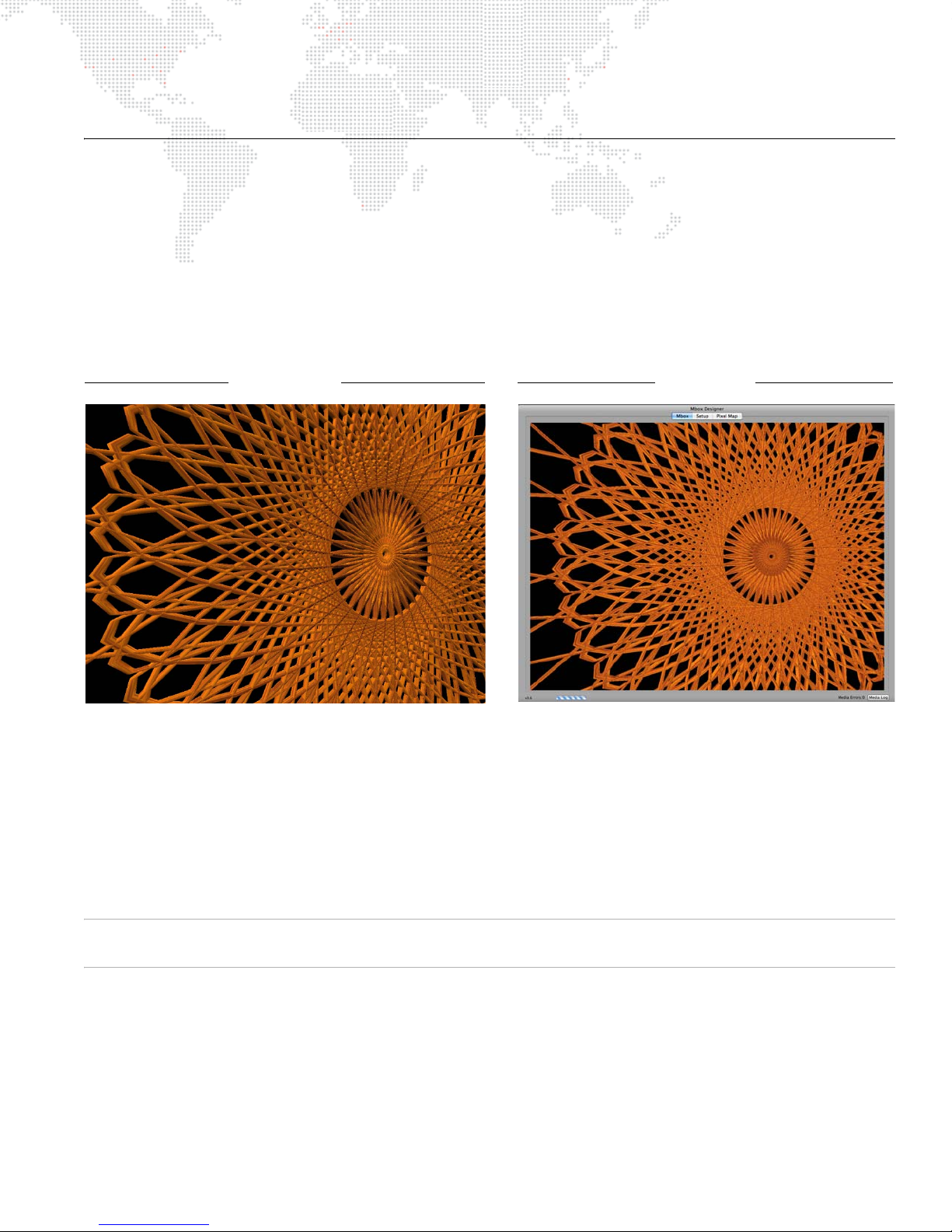
APPLICATION WINDOW
Fullscreen Mode Window Mode
Output to: Preview (Monitor) and Stage Output to: Preview (Monitor) only
Overview
The Mbox Designer application window allows the server’s output to be viewed in either Window or Fullscreen mode
on the preview monitor.
Fullscreen - While in Fullscreen mode, the server’s output (i.e., video) will be displayed at "full screen" without any
user interface showing. In this mode, the output will also be visible on the Stage output of the Dual I/O module.
Window - While in Window mode, the application’s user interface will be displayed. In this mode, the output will NOT
be visible on the Stage output of the Dual I/O module. The Window mode interface contains three tabs: Mbox, Setup,
and Pixel Map as shown in this sample screen below:
The function of the three Window mode tabs is as follows:
+ Mbox tab - used for previewing the server’s video output.
+ Setup tab - used to configure the server. Refer to "Setup" on page 46 for more details.
+ Pixel Map tab - used to configure the Pixel Map and its Art-Net output. Refer to "Pixel-Mapping" on page 107 for
more details.
CAUTION! While in Window mode, there is no visible output from the Dual I/O stage outputs. (A video signal still
exists, but the output is blacked out.)
MBOX® MEDIA SERVER USER MANUAL 45
Page 54
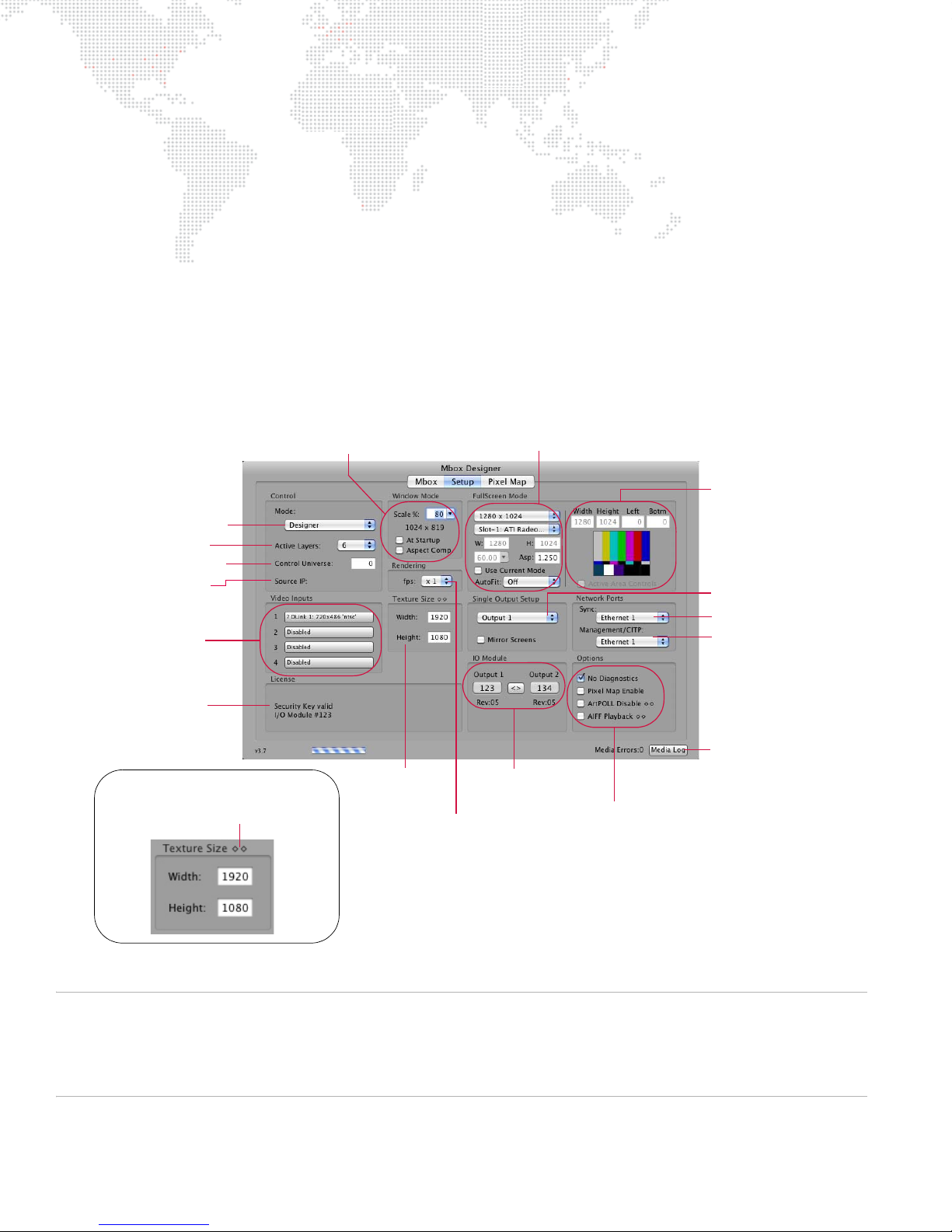
Setup
Sets Screen
Arrangement
Preferences
Sets Active
Area Preferences
Licensing Actions
Sets Local Video Inputs
Sets Window Mode Preferences
Sets Texture Size
Rendering Rate
(Update Rate Divisor Setting)
Sets I/O Module
Output Configuration
Sets Fullscreen Mode Preferences
Sets Sync Network Port
Sets Management/CITP
Opens Media Log
Sets Operating Mode
Sets Universe
Sets # of Layers
Sets Miscellaneous Options
and Display
Port
IP Address of device
Mbox is currently
receiving Art-Net from
"Diamonds" indicate that if this setting
is changed, a software restart is
required for the changes to take effect.
The Setup tab of the Mbox Designer application window is used to:
+ Set the operating mode and Art-Net universe for the Mbox server.
+ Set the application to start in either Window or Fullscreen mode. For Window mode, the window size can be set.
For Fullscreen mode, the resolution can be set.
+ Input License Key to authorize the application.
+ Set a width and height for Textures.
+ Set the network port for CITP communications between Mbox Designer and Mbox Remote and/or any lighting
console or visualizer that supports CITP and MSEX. (Refer to "Mbox Daemon" on page 160 for more information
about using this setting with the Mbox Remote application.)
+ Configure video inputs.
+ Verify the configuration of the connected I/O module output sections.
+ Enable or disable Diagnostics, Deinterlace, Pixel-mapping, and Audio Playback.
Refer to the following pages for in-depth explanations about each of these settings.
Note: The settings configured at this window are stored in a standard Mac Property List (.plist) format. This file,
located at
/Mbox/MboxSettings.plist
that define its operating parameters: window size, screen size, etc. The most important of these settings can be
adjusted from the Setup tab, however, some advanced settings can only be adjusted using Mbox Remote. Refer to
"Mbox Remote Application" on page 159 for more information.
, stores the startup settings for the Mbox Designer software and the variables
46 MBOX® MEDIA SERVER USER MANUAL
Page 55
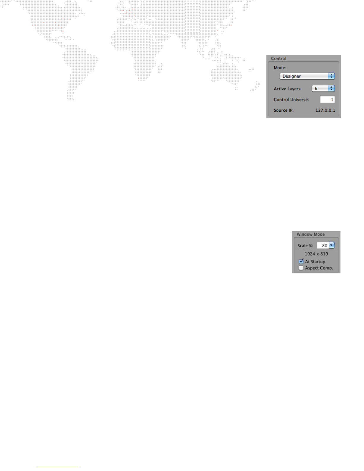
Setup: Control
The Control section is used to set the operating mode, protocol, address and layer
count for the server.
+ Mode - use this pop-up menu to select the desired mode. (Refer to "Operating
Modes" on page 18 for detailed information about each mode.) It is important
that the operating mode match the console profile that is being used. If these
are not properly matched, there may be little or no control over the Mbox
server!
+ Active Layers - use this pop-up menu to select the number of active layers for
the server. (Refer to "Layer Guidelines" on page 29 for information and
cautions about layers.)
+ Control Universe - this field refers to the Art-Net universe that Mbox Designer is "listening to" for control
information. Mbox Designer responds to Art-Net data even when DMX512 is connected to the Dual I/O module.
The I/O module incorporates a built-in DMX512-to-Art-Net converter whose two DMX ports are pre-set to
universe 0 and universe 1. Therefore, the server’s universe should be set to 0 for for use with DMX512 control. If
using a direct Art-Net connection, then modify the server’s universe to match that of the control signal. There are
several methods of referring to the 256 available universes within the Art-Net protocol. Mbox Designer numbers
these universes 0 - 255 and, therefore, universe 0 is the first universe. Other Art-Net devices may call this first
universe "universe 1" or "subnet 0:universe 0." (Refer to "Patching Overview" on page 29 for more information.)
+ Source IP - this field shows the IP address of the device that Mbox is currently receiving Art-Net from on the
universe that is set in the Control Universe field. The IP address is shown to help indicate that Mbox is receiving
data on the selected universe, and as a reference for troubleshooting.
Setup: Window Mode
The Window Mode section is used to configure the behavior of the Mbox Designer
application window when not running in Fullscreen mode. This is intended to be an accurate
representation of the fullscreen output while in Window mode.
+ Scale % - use this pop-up menu to specify a window size in relation to the fullscreen
size. This number is a percentage of the Fullscreen mode. For example, choosing 75
would mean that the Window mode size is 75 percent smaller than the Fullscreen size.
The resulting window size will be shown under the menu (960 x 540 in the example to the
right).
+ At Startup - when this box is checked, the Mbox Designer application will start in Window mode. If it is not
checked, the application will start in Fullscreen mode.
+ Aspect Comp. - when this box is checked, Mbox Designer will change the aspect ratio of Window mode to
compensate for the aspect ratio value selected in the Fullscreen Mode setup area. By default, the Window mode
will be sized to an exact percentage of the Fullscreen mode dimensions (50% of 1920 x 1080 is 960 x 540) and
the Fullscreen aspect ratio is ignored. However, to have the aspect ratio of the Fullscreen mode taken into
account in Window mode, then check the "Aspect Comp" checkbox. This will cause the Window mode
dimensions to take the Fullscreen aspect into account, sizing the window appropriately. Maintaining the correct
aspect is critical for proper aspect viewing in Window mode.
480, but a true aspect ratio of 1.364. A window scale setting of 50% results in a window size of 360 x 240, which
is an actual aspect ratio of 1.5 meaning that the image will be stretched. Checking the "Aspect Comp" checkbox
will result in a window that is 327 x 240, thus keeping the aspect ratio at 1.364.
For example
: NTSC SDI has a resolution of 720 x
MBOX® MEDIA SERVER USER MANUAL 47
Page 56
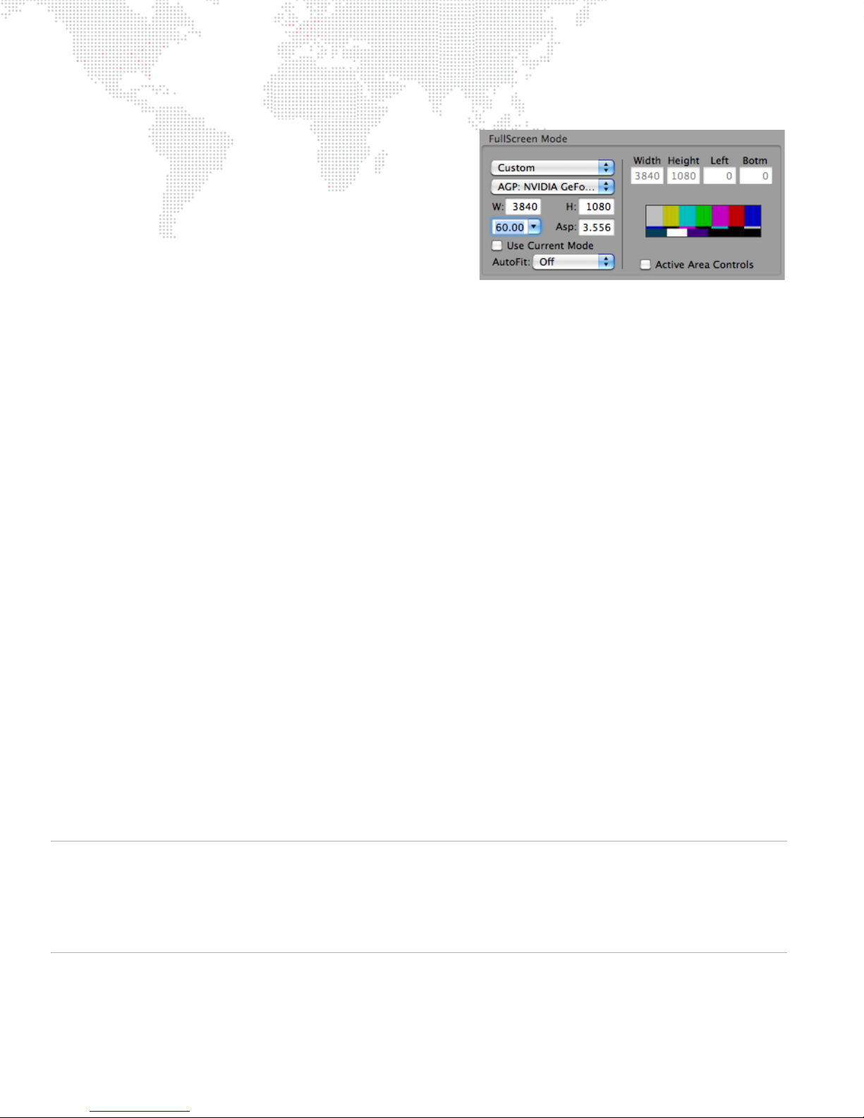
Setup: Fullscreen Mode
The Fullscreen Mode section is used to set the resolution,
frequency, and aspect ratio of the rendering context that Mbox
uses. It is not uncommon to change the Fullscreen Mode settings
since, for example, a standard definition projector would require
different settings than an HD projector, etc.
Getting pixel accurate results from any Fullscreen mode setting
requires the computer to be receiving EDID information that
matches the Fullscreen mode settings. If no EDID is present or if
the EDID does not match the settings entered here, Mbox
Designer will not output the desired resolution and/or frequency
when the software enters Fullscreen mode. Always confirm that you have the appropriate EDID before using the Mbox
Designer software. The Mbox Dual I/O Module provides EDID data to the computer at all time, but if you are using
Mbox Designer without the I/O Module, you will need to supply the appropriate EDID by connecting the output device
(or some alternate EDID spoofing device) to the computer's video output(s).
If "For Current Display" is selected, then the resolution, frequency, and aspect values will be automatically set to
match the settings currently being used for the corresponding output of the computer (i.e., the current Mac desktop
settings). If one of the standard modes is selected (e.g. SDI 720p), the resolution, frequency, and aspect values will be
automatically set to the correct values for that mode. If the custom mode is selected, then resolution, frequency, and
aspect will need to be manually adjusted. For additional sizing and positioning options, the selected FullScreen Mode
setting can be combined with the "Use Current Mode" checkbox and the AutoFit pop-up (see next page). If the
custom mode is selected, the Active Area Controls become available for use.
All video output connectors on the Dual I/O module will output a signal with the same resolution, frequency, and
aspect ratio. The only exception being the SDI outputs which will not output signal if the Fullscreen mode is not
compatible with a standard SDI format.
The Fullscreen mode settings will also be applied to the video signal that is output from the Preview connectors on the
Dual I/O module. Ensure that the preview monitor is able to display an image when receiving a signal with that
resolution and frequency. If the native aspect ratio of the monitor does not match that of the Fullscreen mode, then it
may still display an image, however, it will have the wrong aspect ratio.
Above all, it is most important to tailor the Fullscreen mode settings to the stage device, than to the preview monitor.
The Dual I/O module will not allow output resolutions to be set that may not work with some preview monitors. The
most likely case being when SDI output is used - see "SDI Output (SD - Standard Definition & HD - High Definition)"
on page 61 for further details.
When a certain resolution setting for Fullscreen mode is requested, the operating system will review its EDID
information to see if it is capable of that configuration. If a resolution is requested that does not match a resolution
listed in the current EDID set (see "Connected Display Devices and EDID" on page 57 for further details) then the
operating system will pick a resolution from among those in the current EDID. In this case, Mbox Designer has no
control over what resolution the operating system provides. The selected resolution may be larger or smaller than the
desired Fullscreen mode size. If this happens, there are several possible outcomes which are controlled by the
selection made in the AutoFit pop-up (see next page).
CAUTION! It is strongly recommended that the Mac desktop resolution and refresh rate (frequency) be set to the
same value as the Fullscreen mode settings. If these settings are not the same, then any devices connected to the
media server's outputs (both Preview and Stage) will temporarily lose sync when switching between the Fullscreen
and Window modes or when the Mbox Designer software is relaunched. With some display devices, the results of
losing sync, even temporarily, can be quite disruptive. With identical settings for the Mac desktop and Mbox
Fullscreen mode, there will be no loss of sync. (Desktop resolution can be set in the Mac’s Preferences window.)
48 MBOX® MEDIA SERVER USER MANUAL
Page 57
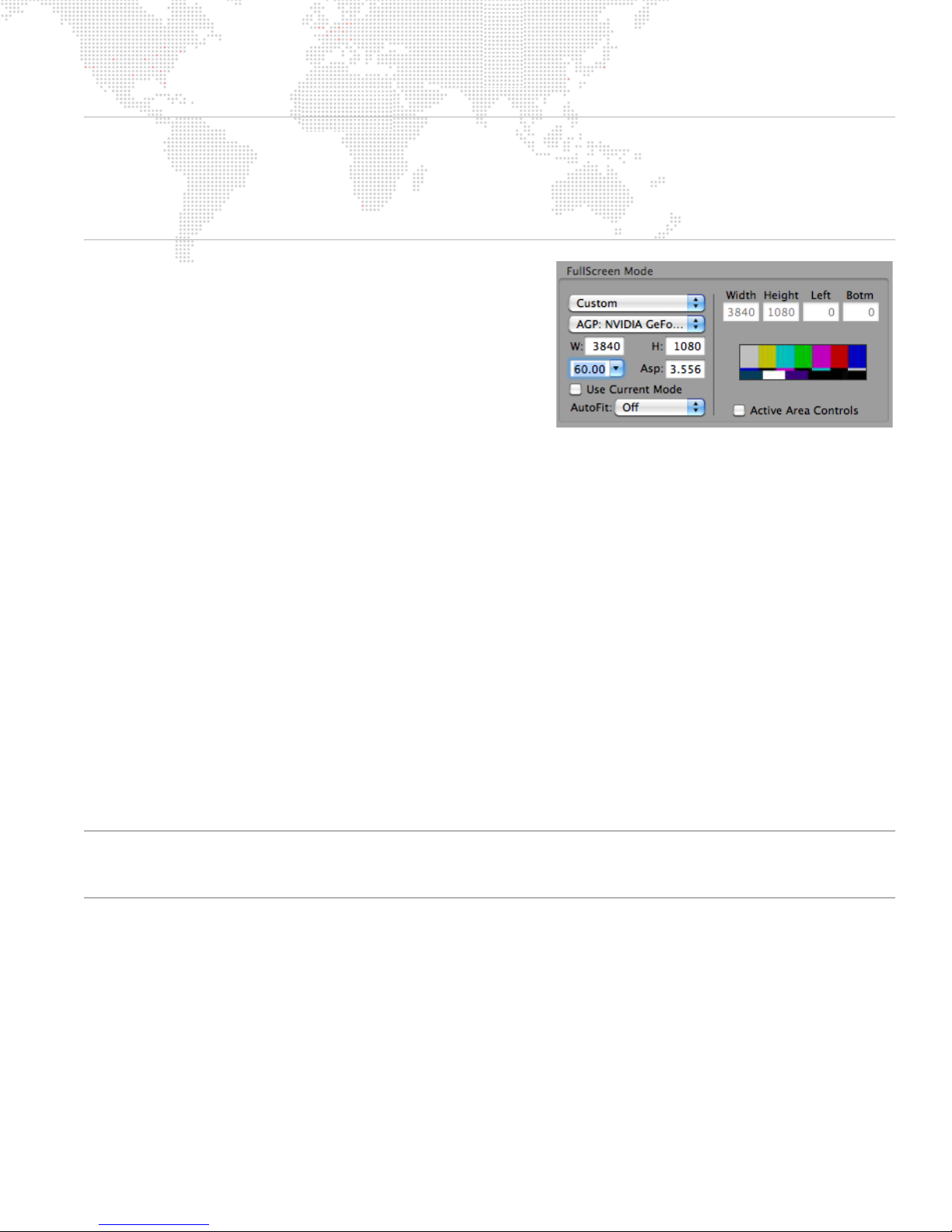
Note: The EDID from the Mbox Dual I/O Module provides EDID with accuracy to two decimal places (e.g., 59.94Hz).
However, the Mac Displays Preference window rounds these frequencies to no decimal places (e.g., 60Hz).
Functionally, Mbox Designer is still able to request and receive the correct frequency when entering Fullscreen mode,
but it is difficult and confusing to set the desktop to the same frequency. To assist in getting the best result, the
Displays drop-down in the menu bar shows frequencies with one decimal place (e.g., 59.9Hz) and therefore this
should be used for accurate selection rather than the Mac Displays Preference window.
+ Use Current Mode - This checkbox is used to force Mbox to
always use the current desktop resolution and frequency, no
matter what Fullscreen Mode resolution and frequency are
selected by the controls above. The fullscreen context will be
positioned and scaled to fit that resolution based on the
selections made in the Fullscreen Mode and AutoFit popups.
+ AutoFit - The Autofit pop-up provides several options:
- Off - If "Off" is selected, the Fullscreen Mode context will
be placed into the bottom-left corner of the received
resolution. If the Fullscreen Mode is smaller than the received resolution, then Mbox will show images with a
black border around them. If the Fullscreen Mode context is larger than the received resolution, then a portion
of Mbox's images may extend off the screen to the right and top.
- Underscan - If "Underscan" is selected, the Fullscreen Mode will be centered in the received resolution and
automatically scaled up or down proportionally until both the width and height fit into the received resolution.
The entire Fullscreen Mode context will be visible. Aspect ratio will be maintained.
- Overscan - If "Overscan" is selected, the Fullscreen Mode will be centered in the received resolution and
automatically scaled up or down proportionally until either the width or height fits into the received resolution.
Portions of the Fullscreen Mode context will not be visible. Aspect ratio will be maintained.
- Anamorphic - If "Anamorphic" is selected, the Fullscreen Mode will be centered in the received resolution and
automatically scaled up or down until both the width and height exactly fits into the received resolution. Aspect
ratio will not be maintained if the aspect of the context does not match the aspect of the received resolution.
+ Active Area Controls - In some cases, it may be necessary to use a specific output resolution but keep content
fixed inside a smaller area of that resolution. For this purpose, Mbox Designer provides a way to embed a custom
active screen area within the larger output area. To use this feature, select "Custom" from the pop-up menu, then
check the "Active Area Controls" checkbox. Enter values for Width and Height to define the smaller display area.
The values for Left and Bottom can be used to position the interior area at a specific location within the larger
area. Note that Active Areas may not work as intended if the "Use Current Mode" checkbox is checked and if the
AutoFit pop-up has a selection other than "Off."
Note: Remember that Mbox Designer’s screen origin is the bottom-left of the output raster. Also, when Active Area
controls are enabled, the Window mode size will be a percentage of the Active Area size rather than the Fullscreen
mode size.
MBOX® MEDIA SERVER USER MANUAL 49
Page 58
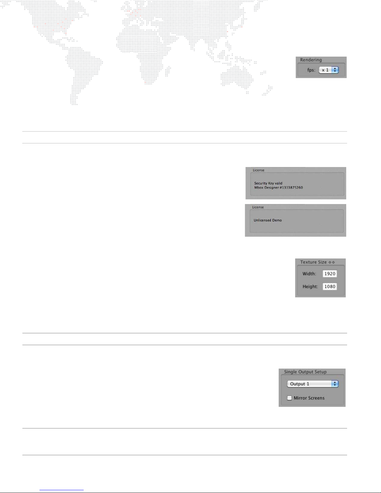
Setup: Rendering
Mbox Designer will always try to output video frames to the Mac graphics card at the same
rate as the current output frequency. However, in some circumstances (e.g., a heavy load),
Mbox Designer is unable to deliver the full number of frames per second, and must
automatically reduce the number of frames it delivers to the graphics card.
At the default setting of x1, Mbox Designer will automatically adjust its update rate. However, if there is poor playback
smoothness, it may be necessary to force Mbox Designer to output a lower number of frames per second to the
graphics card. The optional setting of ÷2 will force Mbox to output a number of frames per second equal to the
numerical value that is 50% of the current fullscreen frequency (e.g., If fullscreen output frequency is 60Hz, then
update rate would be set to 30fps.)
Note: This setting does not affect the output frequency from the graphics card.
Setup: License
The License section is used to display or enter a license key, as required.
A rental Mbox Extreme server will be licensed before shipping as long as a
Dual I/O module remains connected to the computer via USB. If an I/O
module is connected or a purchased USB key (dongle) has been connected
to the computer, that device's serial number will be displayed in this section.
If the software is unlicensed and no I/O module is connected, then the video
output will be watermarked and the application will quit automatically after
30 minutes of use.
Setup: Text ure Si ze
The Texture Size section is used to set the resolution of the largest content (still or movie) that will be displayed.
This setting should be kept to the lowest possible minimum, since overly large values can
negatively affect performance. If you attempt to display content that is larger than the Texture
Size - either in width or height - it will automatically be reduced in size (in 50% increments)
until it fits within the Texture Size. This automatic resizing affects image quality, but it is
necessary to ensure oversized content can be displayed quickly. We recommend finding a
compromise between keeping the Texture Size as small as possible and keeping your image
quality as high as required.
Because the majority of stock content on the Mbox hard-drive is 720
px x 480px, the Texture Size should never be set
lower than this value if you intend to use any stock content.
CAUTION! If changes are made to the Texture Size, the software must be restarted for these changes to take effect.
Setup: Screen Selection (Screen Arrangement)
When using the Single Output operating mode, Mbox Designer can be setup to enter
Fullscreen mode on Output 1 or Output 2 of the I/O module. The other output will
continue to display the Mac desktop. Alternately, the "Mirror Screens" checkbox can be
selected. This will cause the single output to appear on both screens at the same time.
When using either of the Panoramic Wide or Panoramic Dual operating modes, it is
possible to set and adjust the overlap between the two screens and specify whether
they are horizontally or vertically arrayed. Refer to "Operating Modes" on page 18 for more information.
CAUTION! Mirror mode should not be used in show situations because it will cause one or the other of the output
screens to tear. The functionality is included as a convenience. If you require a duplicate of either video output, you
should use the appropriate video signal D/A or splitter.
50 MBOX® MEDIA SERVER USER MANUAL
Page 59
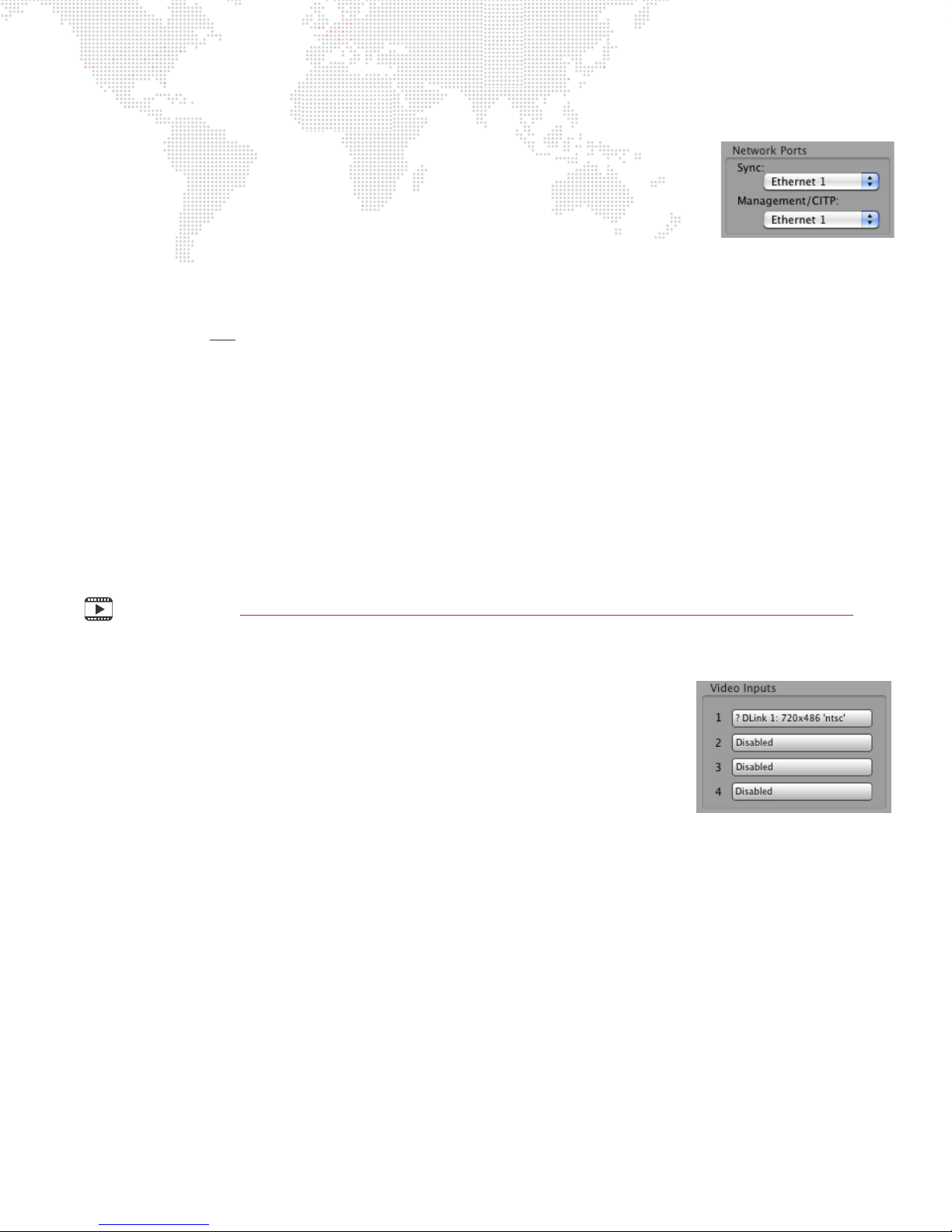
Setup: Network
The Network section is used to configure the Sync, Management, and CITP settings
when connecting two or more Mbox servers.
+ Sync - sets which port the server will use for layer-to-layer and network timecode
sync.
+ Management/CITP - selects the port that the Mbox Daemon application uses for
communication with consoles and the Mbox Remote application. When changes
are made here, it will be reflected 4-5 seconds later in the Daemon screen. (Refer to "Mbox Daemon" on page 28
for more information.)
The available port choices will depend on which Ethernet cables are connected on the servers. It is important to plug
in network cables first
ever unplugged, but if the cable is disconnected the pop-up may not show the port name because it is not active.
+ "Local" is the default setting, but it only allows communication internally. To allow communication to another
computer, an active Ethernet port must be selected.
+ "Ethernet 1" is typically reserved for use with Art-Net input to the Mbox computer, but may be used for
Management/CITP in some cases (i.e., when using a controller that only uses one network port for Art-Net and
CITP, such as Mbox Director).
+ "Ethernet 2" (or additional PCI Ethernet ports) is recommended for all other communications besides Art-Net, if at
all possible. This is done to keep non-critical traffic from interfering with the commands sent to Mbox from the
controller.
Refer to "Networking Multiple Mbox Extreme Servers" on page 26 for more information about the physical Ethernet
connectors.
before making changes to these settings. The settings will be remembered in case the cable is
Training Video: Mbox Media Server Training Video Chapter 6: CITP – Streaming Feedback & Thumbnails
Setup: Video Inputs
The Video Inputs section is used to select and configure the local video inputs to the
server. These inputs can be the standard Video Capture card (Blackmagic Decklink)
or an optional USB or FireWire camera.
The default setting is a particular resolution, so this may need to be changed to
work with all resolutions that are being received by the Mbox server.
When setting up the video inputs, make sure that none of the layers are attempting
to display the video input that is being configured. It may also be necessary to open
the Decklink Preference window (in the Mac System Preferences) to select the type of signal that is being received
(SDI, Composite, or Component) by a Decklink video capture card.
Refer to "Video Input" on page 141 for more information.
MBOX® MEDIA SERVER USER MANUAL 51
Page 60
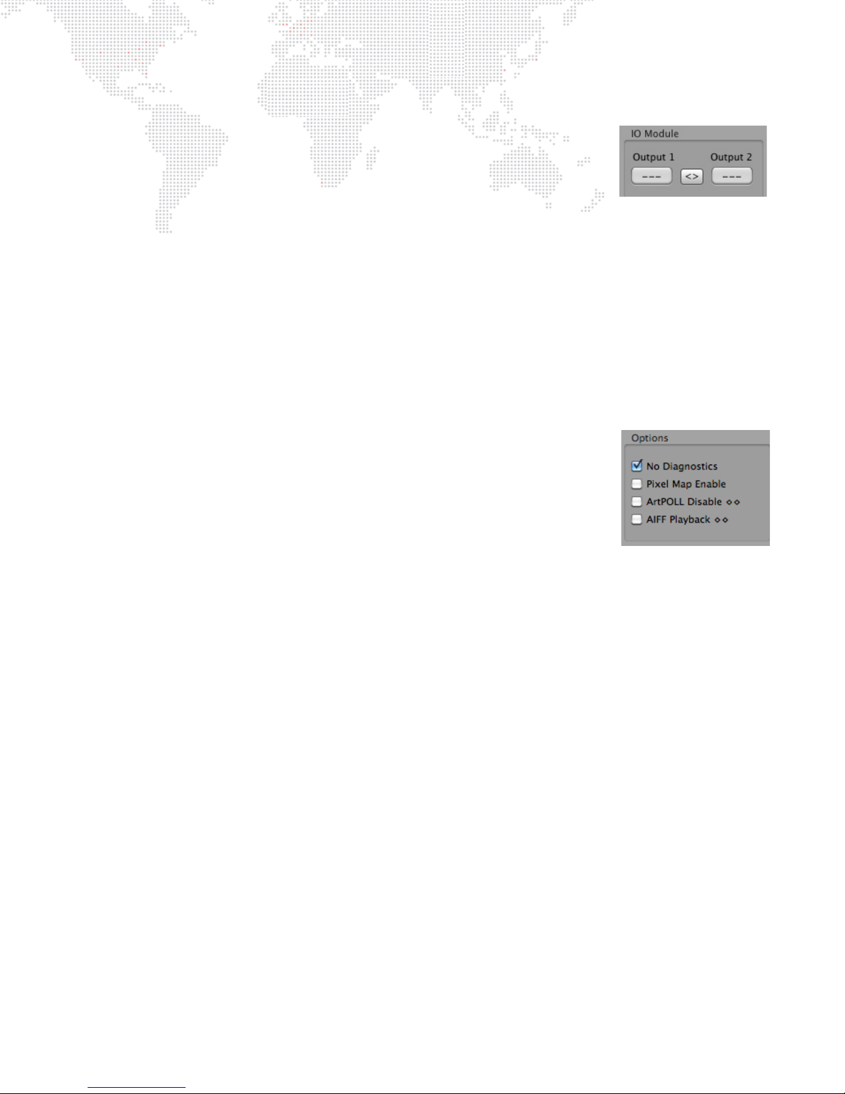
Setup: I/O Module
The I/O Module section is used to verify the configuration of the connected I/O module
output sections. This is important when using Dual Independent mode, as Mbox must
know which output to dim with Camera 1 and which output to dim with Camera 2. When
using Dual Independent mode, if Camera 1 dims Output 2 and Camera 2 dims Output 1,
then the output sections are reversed.
The buttons function as follows:
+ Output 1 / Output 2 - The numbered buttons underneath Output 1 and Output 2 indicate that an I/O module
output section has been found. If "---" is displayed on one or both buttons, this indicates that Mbox cannot find
the I/O module circuit board in question.* These buttons also identify which output section is which. When the
Output 1 button is pressed, the top I/O module output section should flash its LEDs rapidly. Likewise, pressing
the Output 2 button should cause the bottom output section’s LEDs to flash rapidly.
+ < > Button - If the Output 1 button flashes the bottom LEDs and the Output 2 button flashes the top LEDs, press
the "< >" button to swap the order. Verify the swap by pressing the numbered buttons again.
* If this occurs, check all USB connections between the Mac and the Dual I/O module.
Setup: Options
The Options section is used to enable/disable various software features.
+ No Diagnostics - Checking this box will disable the Mbox Designer automatic
error-reporting images such as the icons for locked content, broken movie, etc.
(Checking this box is recommended during show situations).
+ Pixel Map Enable - Checking this box enables the processing of pixel-mapping
patches and the resulting Art-Net output. (Unless you are using pixel-mapping, this
box should be left unchecked.)
+ ArtPOLL Disable - Checking this box turns off Mbox's ability to ask for and receive configuration information from
Art-Net devices on the network. This information is used solely for determining the destination for particular
universes of pixel-mapping Art-Net data. Refer to "Pixel-Mapping" on page 107 for more information.
+ AIFF Playback - Checking this box enables AIFF audio playback. (The Mbox Designer software must be restarted
for this change to take effect.) This checkbox has no effect on embedded audio playback. Refer to "Embedded
Audio Tracks (in QuickTime Movies)" on page 93.
52 MBOX® MEDIA SERVER USER MANUAL
Page 61
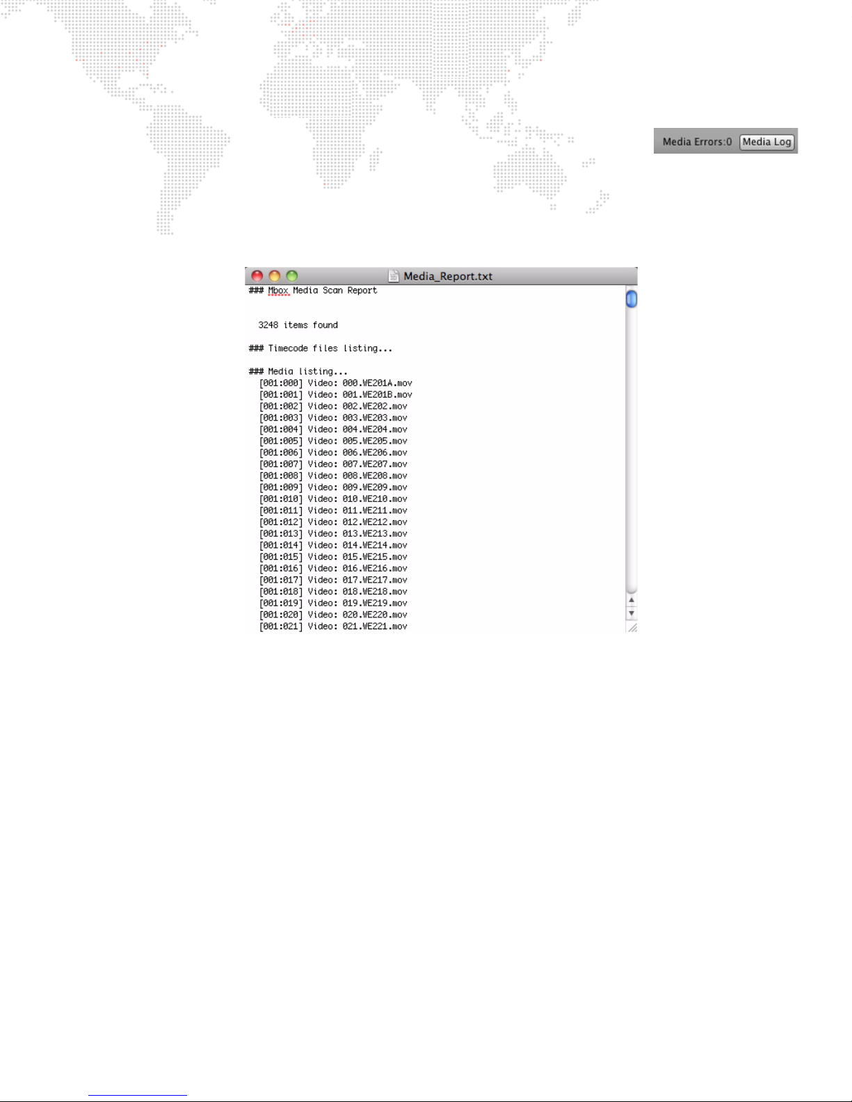
Setup: Media Log (Media Errors)
The Media Log button opens the Mbox Media Report window, which contains a list of all
indexed content (textures, objects, effects, and transitions). When Mbox Designer
performs a media scan, it also looks for files with timecode links, errors, or other conflicts
and reports them. For example, two media files with the same number would be reported as an error in the log. If a file
does not appear in this list, then Mbox will not attempt to play it. Therefore, this list can be used to help identify issues
if media files don't play when requested.
The following is an example Media Report window:
MBOX® MEDIA SERVER USER MANUAL 53
Page 62
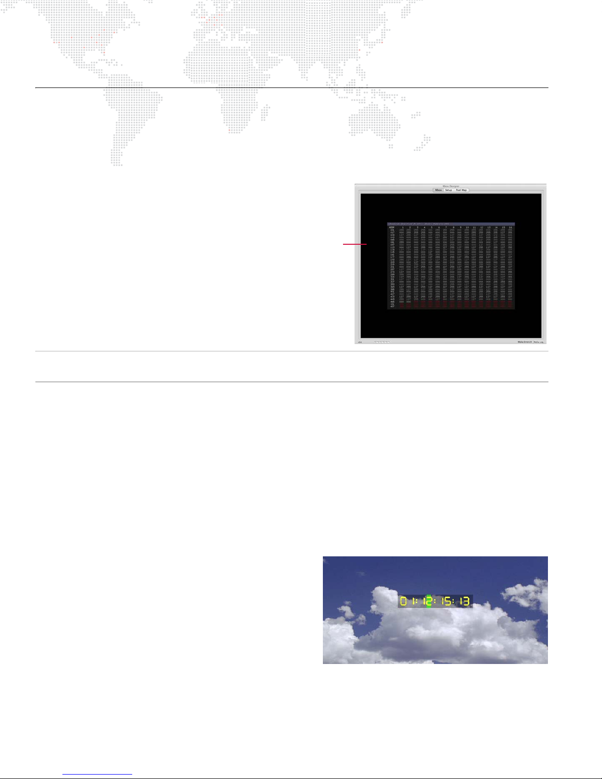
HEADS UP DISPLAYS (HUDS)
Example of the
F4 HUD
Overview
Mbox Designer provides Heads Up Displays (HUDs) that contain detailed information about the server. There are two
methods for calling up most of these HUDs: the Camera fixture control channel or the keyboard. Refer to the chart on
page 212 for a listing of discrete values for the Camera Control Channel. For keyboard activation of the HUDs, press
one of the function keys listed below:
+ F1 - Lights, Camera, Keystone, Shutter HUD
+ F2 - Objects HUD (Texture)
+ F3 - Objects 3D HUD
+ F4 - Control Universe HUD
+ F5 - Pixel-Mapping Previsualization
+ F6 - Pixel-Mapping Sample Areas
+ F7 - Alignment Rectangles
+ F8 - Software Version HUD
+ F9 - Performance HUD
+ F10 - Timecode/Activity HUD
Note: On some keyboards it may be necessary to press a combination of the [fn] key and the function [F1 - F10] key
since the function keys are mapped to OS-specific tasks.
Use the following guidelines when working with the HUDs:
+ Any HUD called from the keyboard will override a request for a HUD by the Camera Control Channel.
+ Press [esc] to clear any keyboard HUD or press the activating key a second time.
+ HUDs activated from the keyboard can also be cleared from the control console through the use of the Camera
Control Channel.
+ [F1] - [F4] have a double toggle action. The first press is for the first universe of control data (DMX512 or Art-Net)
that the server receives (Layers 1-6), while the second press is for the second universe (Layers 7-12).
+ [F5] and [F7] cycle through the two modes for Pixel-Mapping and Alignment Rectangles respectively: Mode 1,
Mode 2, Off. (Refer to "Pixel-Mapping" on page 107 or "Alignment Rectangles" on page 100 for more
information.)
Activity/Timecode Monitoring
Program activity and timecode input can be monitored on the
display. Since the screen may be programmed to go black at
certain points in time, this provides an indication that Mbox
Designer is running, and also provides an on-screen
indication of current timecode.
[F10] will cycle through the five display positions for the
Timecode/Activity HUD: center, top-right, top-left, bottomleft, and bottom-right. The position can also be set using the
Camera Control Channel (page 212).
The green rectangle moves across the gray notification area from left to right, indicating program activity. When valid
timecode is being received (using the Mbox Remote application), the current timecode value (HH:MM:SS:FF) will be
displayed in the notification area. If timecode stops, the timecode notification will go away, but the green activity
rectangle will continue to move.
54 MBOX® MEDIA SERVER USER MANUAL
Page 63
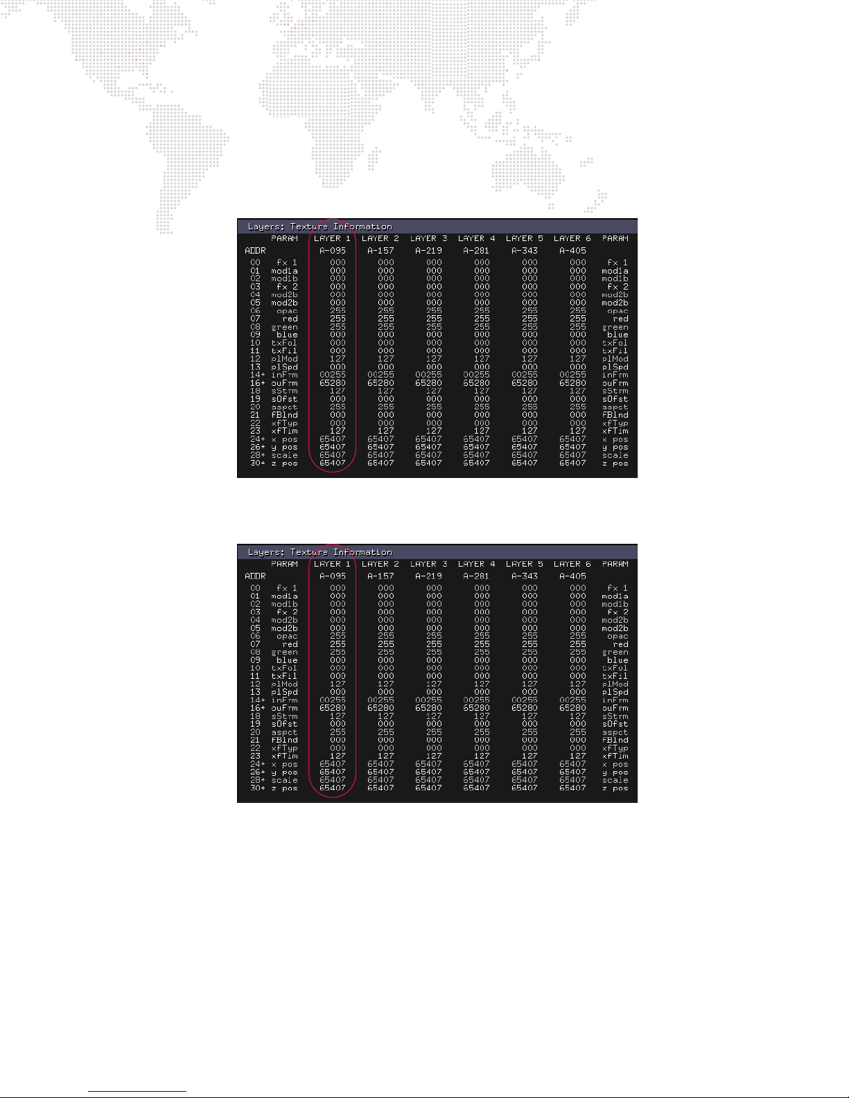
Using the HUDs
The HUDs can be very useful during programming to view the values for fixtures and parameters. When making
changes to the parameters, the values will be immediately reflected in HUD screens. For example, when making
changes to parameters on the Layer 1 Fixture, they can be viewed in the Layer:Texture HUD (F2).
The following screen shows Layer 1 with the default levels:
This next screen shows Layer 1 after some modifications have been made to the effects, color and scale. Note the
altered values in the LAYER 1 column:
All other HUDs will show the same type of changes to the parameter values. Paging through F1, F2, F3 and F4 HUDs
can be helpful during programming to verify value changes, or for troubleshooting patch issues.
MBOX® MEDIA SERVER USER MANUAL 55
Page 64
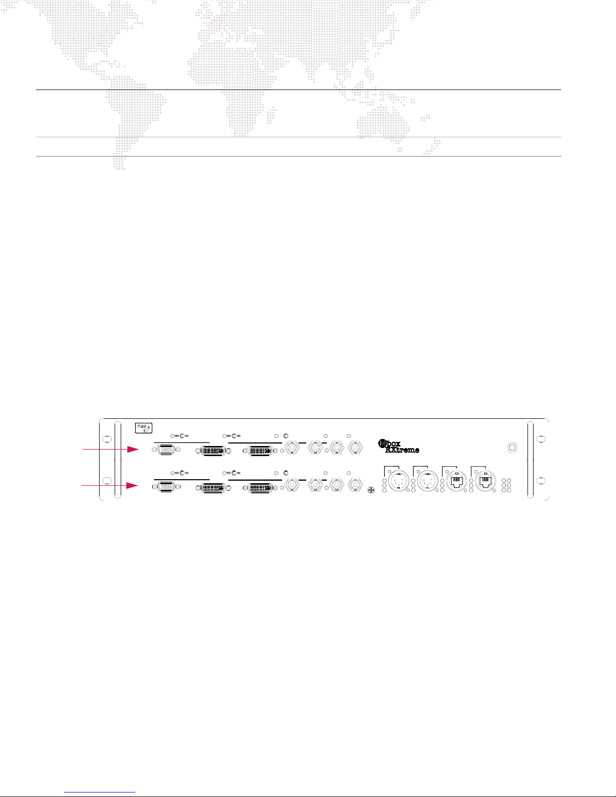
DUAL I/O MODULE
PREVIEW2
A
PREVIEW1
A
STAGEBLACKOUT PREVIEW DIM
TM
SDI 2
B
GENLOCK 2
IN
OUT
ACTIVE
SDI 1
B
PREVIEW DIM
DVI 2
OUTPUT 2
DVI 1
OUTPUT 1
GENLOCK 1
USB
IN
OUT
RDM Rx
RDMT x
DMXRx
INPUT 1
DMX
Dual I/O Module
PORT 2
PORT 1
INPUT 2
ETHERNET
COMPUTER
AB
LINK
Rx
Tx
POWER
ACTIVE USB
MODEL20-9804-0100
EDIDCAPTURE
EDIDCAPTURE
VGA 2
STAGEBLACKOUT
VGA1
Server
Output 1
Server
Output 2
Operation Overview
Note: For an overview of Dual I/O module components, refer back to "Dual I/O Module" on page 8.
The function of the Dual I/O module is to provide video conversion, final dimming of the video signal, and to send
EDID information to the Mac computer. The module also handles DMX512 and Art-Net input for the computer.
The module receives two DVI outputs from the computer and uses these two signals to provide two separate output
sections with DVI and SDI preview, and DVI, VGA (RGBHV) and SDI (HD & SD) stage outputs. The two output sections
are functionally identical, but are completely independent so that each can be configured for its own output
requirements. The I/O module allows the video signal to be easily reconfigured to work with many display devices
without the need for an external scan converter.
During operation, the I/O module can suppress the stage output so that "inappropriate" content - such as the Mac
desktop or Mbox Designer application frame - will not be displayed on the stage output (e.g., when in Window mode).
I/O module settings can be configured using the Mbox Setup tab as covered in "Setup: I/O Module" on page 52.
Notes:
+ During video conversion there is no change to resolution, scaling, or position, as it is purely a format change from
one signal to another.
+ There are fewer possible resolutions for SDI, so sometimes the module may not be able to output a signal.
+ The module can do a complete blackout or dim the RGB to levels below full output. This can be done by dimming
at the control console, from the Mac computer, or by using the STAGE BLACKOUT switch.
Figure 3-1: Dual I/O Module Server Output Sections
56 MBOX® MEDIA SERVER USER MANUAL
Page 65
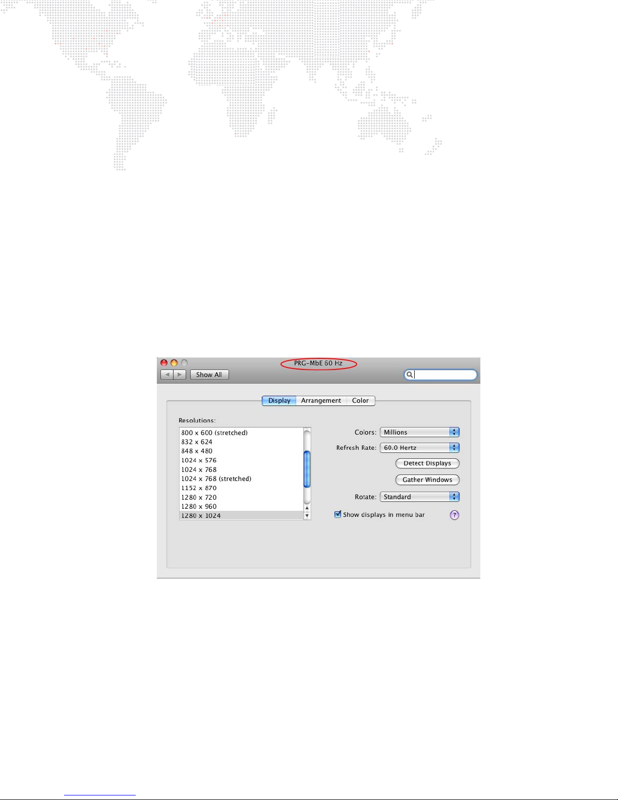
Connected Display Devices and EDID
Overview
Without special hardware or software, a typical computer can only output video resolutions and frequencies that are
supported by the display equipment that is connected to it. Display devices communicate their required input
configurations via EDID (Extended Display Identification Data), which is essentially a communication protocol used
between a device and a computer.
In order to provide some of the specialized outputs - for example, the various SDI signals - from the Dual I/O module,
the computer must be told that it can output certain frequencies or resolutions that are required. For this reason, the
I/O module incorporates EDID management for both video outputs on the computer. The I/O module always tells the
computer what frequencies and resolutions are possible, and EDID from connected devices is never passed through
directly to the computer unless "captured" into the I/O module (as will be covered later in this section).
When connecting the Mbox video outputs to a display device, you must ensure that the display device's desired
resolution and frequency appear in the Mac Displays Preference window so that it will be possible to select the
resolution and frequency here and in the Fullscreen Mode section of the Setup tab (refer to "Setup: Fullscreen Mode"
on page 48). If the desired resolution and frequency are not available, then you must change to an alternate EDID set
or capture the EDID settings from the connected display device.
The currently selected EDID set for each output is shown in the Mac Displays Preference window. Each output of the
server will show a configuration similar to the example in Figure 3-2 below. The header of each window will display
the name of the EDID set (e.g. PRG-MbE 60Hz as shown below) or the name of the captured EDID (e.g. LCD
2408WFP).
Figure 3-2: Mac Display Preferences
MBOX® MEDIA SERVER USER MANUAL 57
Page 66
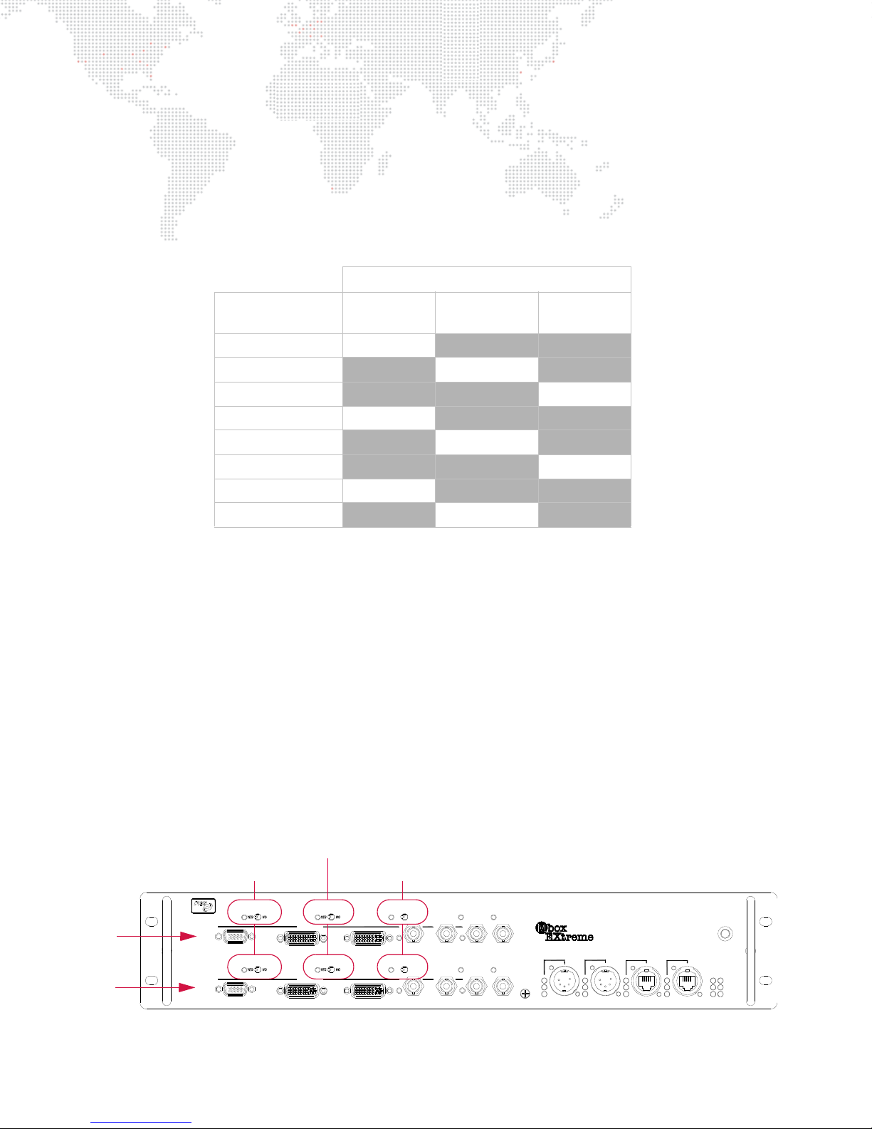
Switching Between Modes
PREVIEW2
A
PREVIEW1
A
STAGEBLACKOUT PREVIEW DIM
TM
SDI 2
B
GENLOCK 2
IN
OUT
ACTIVE
SDI 1
B
PREVIEW DIM
DVI 2
OUTPUT 2
DVI 1
OUTPUT 1
GENLOCK 1
USB
IN
OUT
RDM Rx
RDMT x
DMXRx
INPUT 1
DMX
Dual I/O Module
PORT 2
PORT 1
INPUT 2
ETHERNET
COMPUTER
AB
LINK
Rx
Tx
POWER
ACTIVE USB
MODEL20-9804-0100
EDIDCAPTURE
EDIDCAPTURE
VGA 2
STAGEBLACKOUT
VGA1
Server
Output 1
Server
Output 2
EDID Capture
Stage Blackout Switch
Preview Dim Switch
Switch and LED
The Mbox server can operate in one of three default EDID settings, or, if the default sets are not appropriate for the
connected display devices, then a custom EDID setting may be captured.
Default EDID Sets - Three default sets of EDID data stored within the Dual I/O module provide the necessary
information to work with standard computer display resolutions and frequencies, and typical SD and HD-SDI
resolutions and frequencies. These three sets include common VESA and SD/HD SDI resolutions at different
frequencies. The following chart shows the "usable" frequencies in each of the three EDID sets.
(This chart assumes the user is selecting a non-VESA resolution i.e. NTSC, PAL, 720p, 1080p, 1080i *)
Default EDID Sets
Frequency Entry
on Setup Tab
SET 1
60Hz EDID
SET 2
59.94Hz EDID
SET 3
50Hz EDID
60Hz 60Hz X X
59.94Hz
50Hz
30Hz 30Hz
29.97Hz
25Hz
24Hz 24Hz
23.98Hz
X59.94HzX
X X50Hz
X X
X29.97HzX
X X25Hz
X X
X23.98HzX
* VESA resolutions like 1024x768, 1280x1024 etc. should use 60Hz frequency setting only.
Custom EDID Capture - At times, the default sets of EDID data may not be appropriate for the connected display
devices. In these cases, special steps can be taken to provide display-specific EDID information to the computer. This
function is referred to as "EDID Capture." Any EDID compliant device can be connected to the Dual I/O module and
have its EDID data read and captured. Captured data is stored in non-volatile memory in the I/O module until it is
replaced when the firmware is updated or the EDID data is intentionally reverted back to standard settings.
Guidelines:
+ Capturing EDID data from a specific device requires a DVI or VGA connection.
+ When capturing EDID, the I/O module looks at the ports in a specific order (Stage DVI, Stage VGA, Preview DVI)
and the first connected device found is the only data that is captured. Typically, only one device would be
connected to the stage DVI or VGA connector as appropriate. To reduce the possibility of incorrect capture, it is
best if only one device is connected at a time.
+ EDID will need to be captured for each server output section separately (Figure 3-3) . When using one of the dual
output modes, you must use the same EDID set on both outputs.
58 MBOX® MEDIA SERVER USER MANUAL
Figure 3-3: Dual I/O Module
Page 67
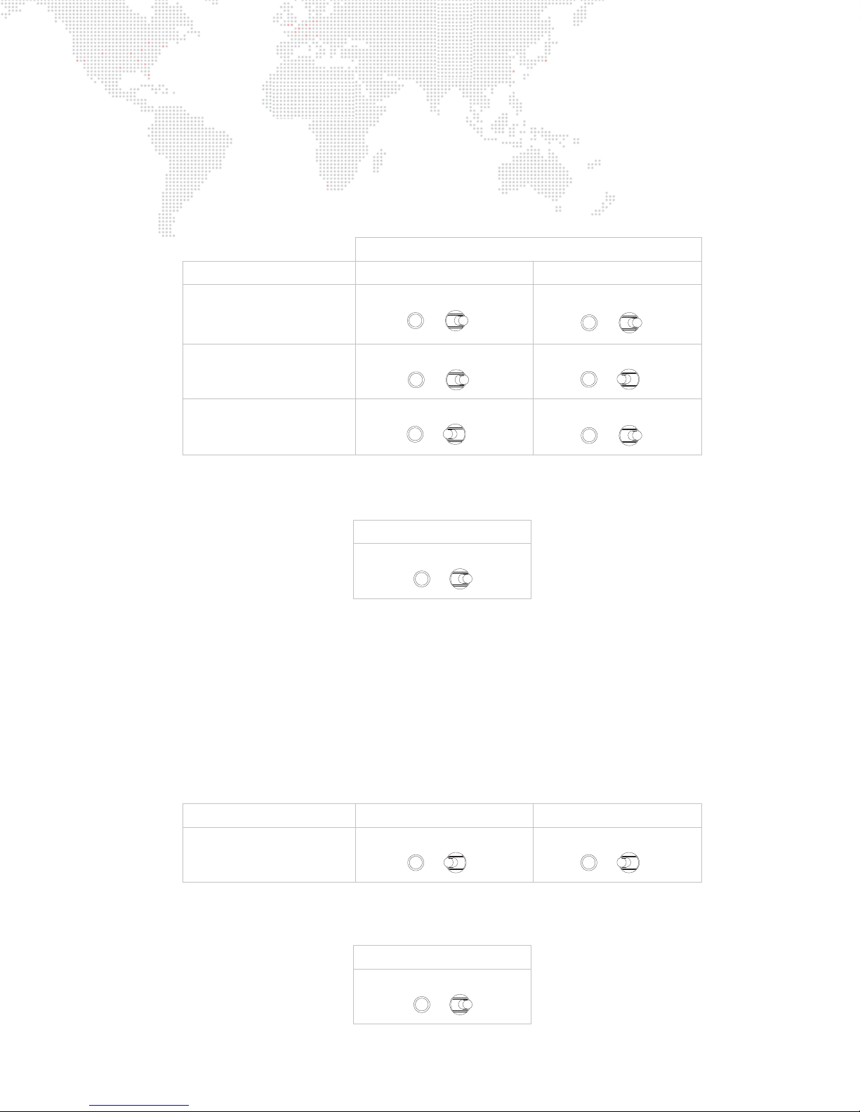
Switching Between Standard EDID or Capturing EDID
YES NO
YES NO
YES NO
YES NO
YES NO
YES NO
YES NO
YES NO
The EDID set can be changed using the Stage Blackout and Preview Dim switches located on the front of the I/O
module. The combination of these switch settings (as either Yes or No) will determine the default EDID set - or, if a
custom EDID will be captured - when the EDID Capture switch is engaged.
To switch between the three standard EDID sets:
Step 1. Place Stage Blackout and Preview Dim switches in one of the following configurations (according to the
desired set):
Switch Positions:
Desired EDID Set Stage Blackout Switch Preview Dim Switch
NO
Set 1: 60Hz
NO YES
Set 2: 59.94Hz
NO
YES
NO
Set 3: 50Hz
Step 2. Flip momentary EDID Capture switch to the right and hold in position. The indicator LED will flash rapidly for
four seconds. (During this time, the switch can be released and no capturing action will take place.)
EDID Capture Switch
To Right
To capture a custom EDID:
Refer to the guidelines on the previous page for more information.
Step 1. Quit Mbox Designer.
Step 2. Open Mac Displays Preference window (Figure 3-2).
Step 3. Connect monitor to preview output of the other output section (not being programmed).
Step 4. Remove all DVI or VGA connectors from output section you wish to program.
Step 5. At output section being programmed, reconnect only the device from which you want to capture EDID data.
Step 6. Set both Blackout and Preview Dim switches to their "Yes" position:
Desired EDID Set Stage Blackout Switch Preview Dim Switch
YES YES
Capture from DVI/VGA
Step 7. Flip momentary EDID Capture switch to the right and hold in position. The indicator LED will flash rapidly for
four seconds. (During this time, the switch can be released and no capturing action will take place.)
EDID Capture Switch
To Right
MBOX® MEDIA SERVER USER MANUAL 59
Page 68

Step 8. After four seconds, the LED will stop flashing and will remain on for about two seconds. During this time the
EDID data is being captured.
Step 9. Once the external capture is complete, the LED will again flash, but more slowly than before. At this point,
release the switch.
Step 10. At Mac Displays Preference window, click Detect Displays button. The computer will re-sync the outputs
and the new EDID will be applied. (You can connect your display devices at this point.)
Step 11. You should have a viewable resolution on the output that you were reconfiguring. You may still need to
change this resolution (using the Displays Preference window) to a specific desired resolution.
Step 12. Perform steps 1 - 9 on the other output section of the I/O module.
CAUTION! Because EDID data in the Dual I/O module can be reprogrammed, the computer can output resolutions
that your display devices may not support. If you connect a display device and cannot get a picture, even with the
Mbox Designer software not running (you may see a message like "Unsupported resolution" on the display), then you
should revert the EDID data to the standard 60Hz set. Note also that if the EDID has been set to a mode where you
cannot view the desktop, then you will be unable to view the Display Preferences window. Refer to the steps below.
To return the desktop view:
If the EDID in the I/O module has a resolution and frequency that the connected display device does not support, it
can result in no picture on the desktop. Without a picture, you can switch EDID sets using the switches, but you can't
press the "Detect Display" button because it is not visible on the screen.
In order to revert to a standard EDID set so the desktop can be seen, it will be necessary to view the Mac Displays
Preference window. If you cannot view the desktop (and therefore, this window) due to previous EDID changes, then
do the following:
Step 1. Connect a DVI monitor to Preview 1, and disconnect everything else.
Step 2. Capture EDID from that monitor. (Refer to page 59.)
Step 3. Unplug and replug DVI from rear of Mac, or shutdown and reboot the computer.
Step 4. Provided Mbox Designer is not running, you should now be able to see the Mac desktop on the monitor.
Step 5. Open Mac Displays Preferences window. Press Gather Windows button to get both of the setup windows
onto that monitor.
Step 6. Either set the other output to a working resolution/frequency (for the display devices you have) or again
change EDID to something compatible.
Step 7. Press Detect Displays. The other output should now work with your display device.
Step 8. Connect monitor to the other output, and reconfigure the first one as desired.
To revert to a standard EDID set:
If the custom EDID data in the I/O module is no longer needed, simply return the configuration to one of the standard
EDID sets as follows:
Step 1. Quit Mbox Designer.
Step 2. Connect a monitor to both output sections (Figure 3-3).
Step 3. Open Mac Displays Preference window (Figure 3-2).
Step 4. Set Stage Blackout and Preview Dim switches to new positions as required. Refer to chart on page 59.
Step 5. Flip momentary EDID Capture switch to the right and hold in position. The indicator LED will flash rapidly for
four seconds. (During this time, the switch can be released and no capturing action will take place.)
60 MBOX® MEDIA SERVER USER MANUAL
EDID Capture Switch
To Right
Page 69

Step 6. After four seconds, the LED will stop flashing and will remain on for about two seconds. During this time the
EDID data is being captured.
Step 7. Once the external capture is complete, the LED will again flash, but more slowly than before. At this point,
release the switch.
Step 8. At Mac Displays Preference window, click Detect Displays button. The computer will re-sync the outputs
and the new EDID will be applied. (You can connect your display devices at this point.)
Step 9. You should have a viewable resolution on the output that you were reconfiguring. You may still need to
change this resolution (using the Displays Preference window) to a specific desired resolution.
Step 10. Perform steps 1 - 7 on the other output section of the I/O module.
SDI Output (SD - Standard Definition & HD - High Definition)
IMPORTANT! This requires connection to a Dual I/O Module. If you are using Mbox Designer without the Dual I/O
Module, you will not be able to output SDI.
The Mbox Designer software supports SD/HD-SDI output directly from the Dual I/O module without need for a scan
converter. SDI can be sent from both outputs of the I/O module simultaneously. A standard DVI monitor may need to
be connected to the Preview output(s) of the I/O module so that the Mac desktop can be viewed when Mbox Designer
is not running in Fullscreen mode.
In order to output SDI, the Mac Graphics card must be set to display output resolutions and frequencies that some
DVI monitors may not support. The EDID spoofing built into the Dual I/O module allows the unit to output the special
resolutions and frequencies.
In order to output SDI, Mbox Designer simply needs to be configured to use the appropriate Fullscreen mode setting
and the Dual I/O module will automatically output SDI at that resolution and frequency setting (refer to "Connected
Display Devices and EDID" on page 57 for further info on frequency settings).
When SDI has been enabled, normal VGA or DVI monitors connected to the Dual I/O module may not be able to
display a picture. DVI monitors provide the most compatibility, but compatibility is not guaranteed. However, the two
SDI connectors (A & B) on the face of the module do act as Preview and Stage SDI outputs. SDI A will be the Stage
output, and SDI B will be the Preview output. In this way, an SDI monitor can be used with the SDI preview output.
Note: Most SD-SDI monitors cannot display an HD-SDI signal, but HD-SDI monitors can display SD-SDI signals.
When entering the Fullscreen mode with Mbox Designer set to output an SDI-compatible resolution, the SDI indicator
LED to the left of SDI connector A will illuminate. SDI will be output if one of the pre-determined SDI settings is
selected or if the Custom mode is configured with a resolution and frequency that matches one of the possible SDI
formats.
When using SDI output, it may not be possible to run the Mac desktop at the same resolution and frequency as the
selected (SDI) Fullscreen mode. If also using Genlock, this means that genlock sync will be lost when switching
between Fullscreen and Window modes or when quitting the Mbox Designer software (see "Setup: Fullscreen Mode"
on page 48 for more information). In this case, plan accordingly to enter Fullscreen mode with enough time to allow
the genlock to sync.
The following SDI resolutions are supported:
+ SD - NTSC 480i (720 x 480) @ 60Hz (non-square pixels)
+ SD - PAL 576i (720 x 576) @ 50Hz (non-square pixels)
+ HD - 720p (1280 x 720) @ 59.94/60Hz
+ HD - 1080i (1920 x 1080) @ 50/59.94/60Hz
+ HD - 1080p (1920 x 1080) @ 23.98/24/25/29.97/30Hz
MBOX® MEDIA SERVER USER MANUAL 61
Page 70
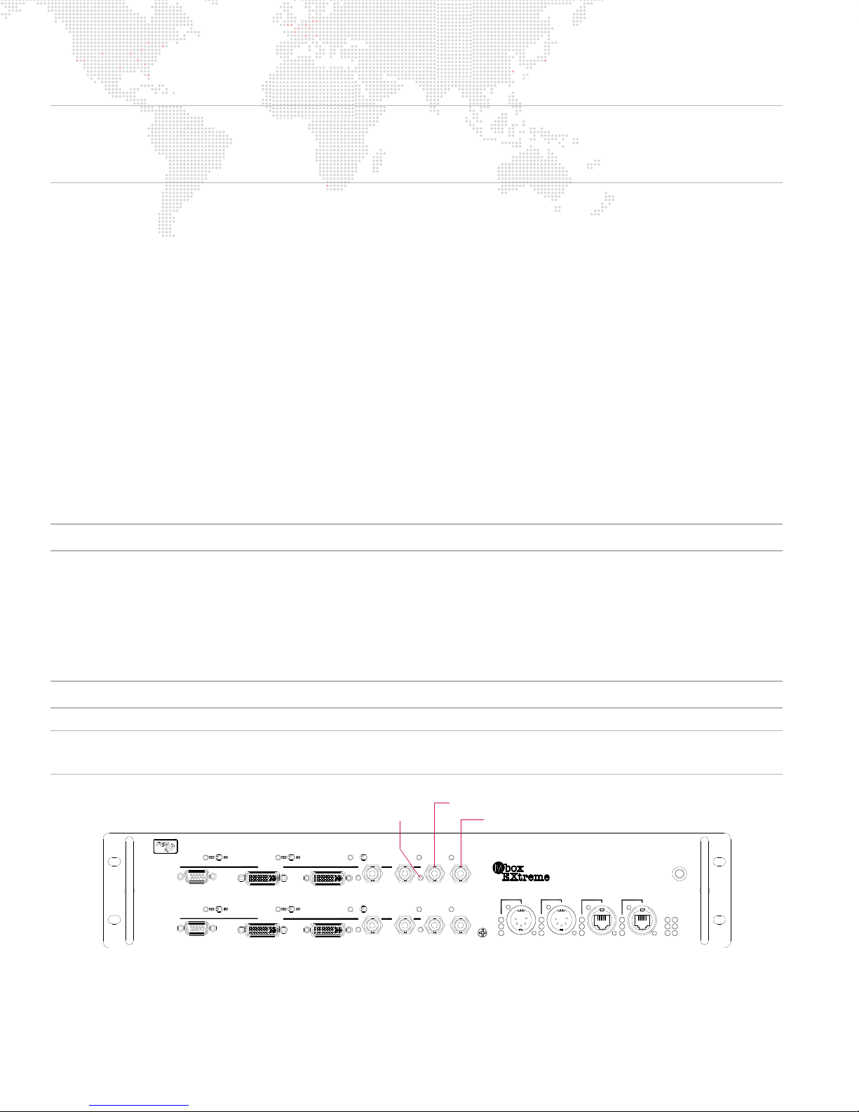
Note: Many standard resolution/frequency combinations can be selected in the Fullscreen mode section of the Setup
PREVIEW2
A
PREVIEW1
A
STAGEBLACKOUT PREVIEW DIM
TM
SDI 2
B
GENLOCK 2
IN
OUT
ACTIVE
SDI 1
B
PREVIEW DIM
DVI 2
OUTPUT 2
DVI 1
OUTPUT 1
GENLOCK 1
USB
IN
OUT
RDM Rx
RDMT x
DMXR x
INPUT 1
DMX
Dual I/O Module
PORT 2
PORT 1
INPUT 2
ETHERNET
COMPUTER
AB
LINK
Rx
Tx
POWER
ACTIVE USB
MODEL20-9804-0100
EDIDCAPTURE
EDIDCAPTURE
VGA 2
STAGEBLACKOUT
VGA1
* Only the top set of Genlock connectors (GENLOCK 1) are connected to the Mac computer.
Genlock In
Genlock Out *
Genlock LED
tab. To use a resolution and/or frequency that is different from the standard choices, select "Custom" on the pop-up
menu and manually enter the resolution and frequency in the fields below the pop-up. Refer to "Setup: Fullscreen
Mode" on page 48.
Example - To get Mbox to output 720p/59.94Hz, do the following:
Step 1. Open Mac Displays Preference window.
Step 2. Using switch combinations outlined on page 60, change EDID set on both outputs of the I/O module to the
PRG-MbE 59.94Hz set.
Step 3. At Displays Preference window, click Detect Displays button. Reset desktop resolution/frequency of both
displays to 1280 x 720 and 59.94Hz.
Step 4. At Mbox Setup tab Fullscreen mode section, select "HD-SDI 720p59.94" in pop-up menu.
When using the Custom Fullscreen mode, the Frequency combo box has preset values that cover all of the
standard frequencies. The result of the settings will depend on the current EDID set (an "X" indicates an
invalid combination that should not be used).
The result of any selection when using custom EDID (captured from an external display device) will depend on which
frequencies the device supports. If the selected frequency is supported in the custom EDID set, you will get it. In all
cases, when you attempt to use an unsupported frequency, you will get an undesirable result.
Genlock (Generator Lock)
Note: This section only applies to the rental Mbox Extreme server.
The function of Genlock is to tell the server when to start drawing each frame of video. This function can be synced so
that all Mbox Extreme servers in the system will start drawing at the same time. The Mbox Dual I/O Module provides
the the ability to synchronize - or "genlock" - the video outputs of the module to an external genlock source. The I/O
module can also output a genlock signal to other devices, as desired. Genlock Input and Output connectors are
provided on the I/O module for this purpose. (Note that only the top pair of Genlock connectors on each module are
active.)
Note: The Dual I/O Module only supports composite sync input. It does not support tri-level sync.
CAUTION! The Genlock Out is not a pass-thru. This output should only be used if you wish to use that particular
Mbox Extreme server as the master for syncing (rather than a daisy-chain port).
62 MBOX® MEDIA SERVER USER MANUAL
Figure 3-4: Dual I/O Module Genlock Connectors
Page 71
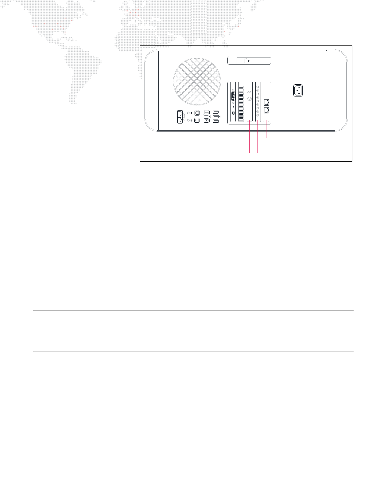
The Mbox Genlock feature uses
Figure 3-5: Mac Computer Rear View (v3.5)
21
audio
optical
in out
Graphics Card
Genlock Card
Video Capture Card
Ethernet Card
an additional connection between
the rear of the I/O module and the
Genlock card in the Mac
computer. This card is located
next to the Graphics card and has
two LED indicators - one red and
one green - which function as
follows:
+ If the card is receiving power
but no data, the red LED will
turn on.
+ When the card is receiving
data (i.e. when a genlock
input is connected to the I/O
module), the red LED will turn
off and the green LED will turn
on.
+ When a genlock input is first
connected to the I/O module, a green LED to the left of the Genlock In connector will flash rapidly. This is to
indicate that the module has recognized the presence of an incoming signal and is attempting to synchronize to it.
+ Once synchronization has occurred, the LED will stop flashing and stay illuminated. It may take up to two minutes
for the synchronization process to complete, so it is advisable to establish sync a few minutes before needed.
+ If the green LED flashes rapidly when genlock is connected, this indicates an input frequency that does not match
(too fast or too slow) the frequency that the Mac is outputting.
+ If the green LED flashes rapidly then turns off altogether, this is a likely indication that the input signal is not
standard composite sync. Check the type and quality of the signal.
To ensure that genlock input and output work successfully, make sure that the devices being synchronized are set to
refresh at identical rates. If Mbox Designer is set to output video with a refresh rate of 59.94Hz, then its output can
only be usefully connected to another device that is set to refresh at 59.94Hz. Similarly, if you intend to synchronize
Mbox video output to a video source refreshing at 50Hz, you must set Mbox Designer to output video with a refresh
rate of 50Hz. Please note that not all video refresh rates are available on all devices or are compatible with all devices.
You will need to find a rate that works with all of your equipment.
CAUTION! If you attempt to synchronize an Mbox’s video output to an external source with a conflicting refresh rate,
the two devices will never synchronize. The genlock LED on the front of the Dual I/O Module will continue to flash
forever. Additionally, it is strongly recommended that you configure the Mac desktop resolution to be the same as the
Mbox Fullscreen mode (see "Setup: Fullscreen Mode" on page 48) as failing to do so will result in a loss of genlock
synchronization every time you quit Mbox Designer or switch from Fullscreen to Window mode.
MBOX® MEDIA SERVER USER MANUAL 63
Page 72

ENHANCING MBOX PERFORMANCE
Recommended Practices
Use the following recommended practices to enhance the performance of your Mbox system:
+ Disable any screen-savers.
+ Disable File Sharing and Remote Management (any and all sharing, in fact).
+ Turn off automatic software updates.
+ Disable Spotlight on all connected hard-drives by placing them in the Privacy table.
+ Set Energy Saver settings to disable computer and display sleep, and to stop hard-drives from being put to sleep.
+ If using a laptop with two graphics modes, disable automatic switching (use max performance).
+ Disable Time Machine.
+ Disconnect the computer from the internet.
+ Disable Expose and Spaces.
+ Turn off FileVault and Firewall.
+ Turn off Bluetooth.
+ Turn off automatic data and time setting.
+ Quit all other applications!
+ Disable unnecessary background processes.
64 MBOX® MEDIA SERVER USER MANUAL
Page 73

4.
ADVANCED FEATURES
This chapter provides instructions for using the advanced features of the Mbox Designer software.
+
3D OBJECTS AND DIGITAL GOBOS
+ ANIMATED TEXTURES
+ LAYER COPY
+ DRAWMODES
+ LAYER BLENDING
+ SPECIAL EFFECTS
+ TEXT FILES
+ AUDIO
+ SYNCHRONIZATION
+ ALIGNMENT RECTANGLES
+ EFFECTS AND TRANSITIONS
+ PROJECTION MAPPING
Page 74
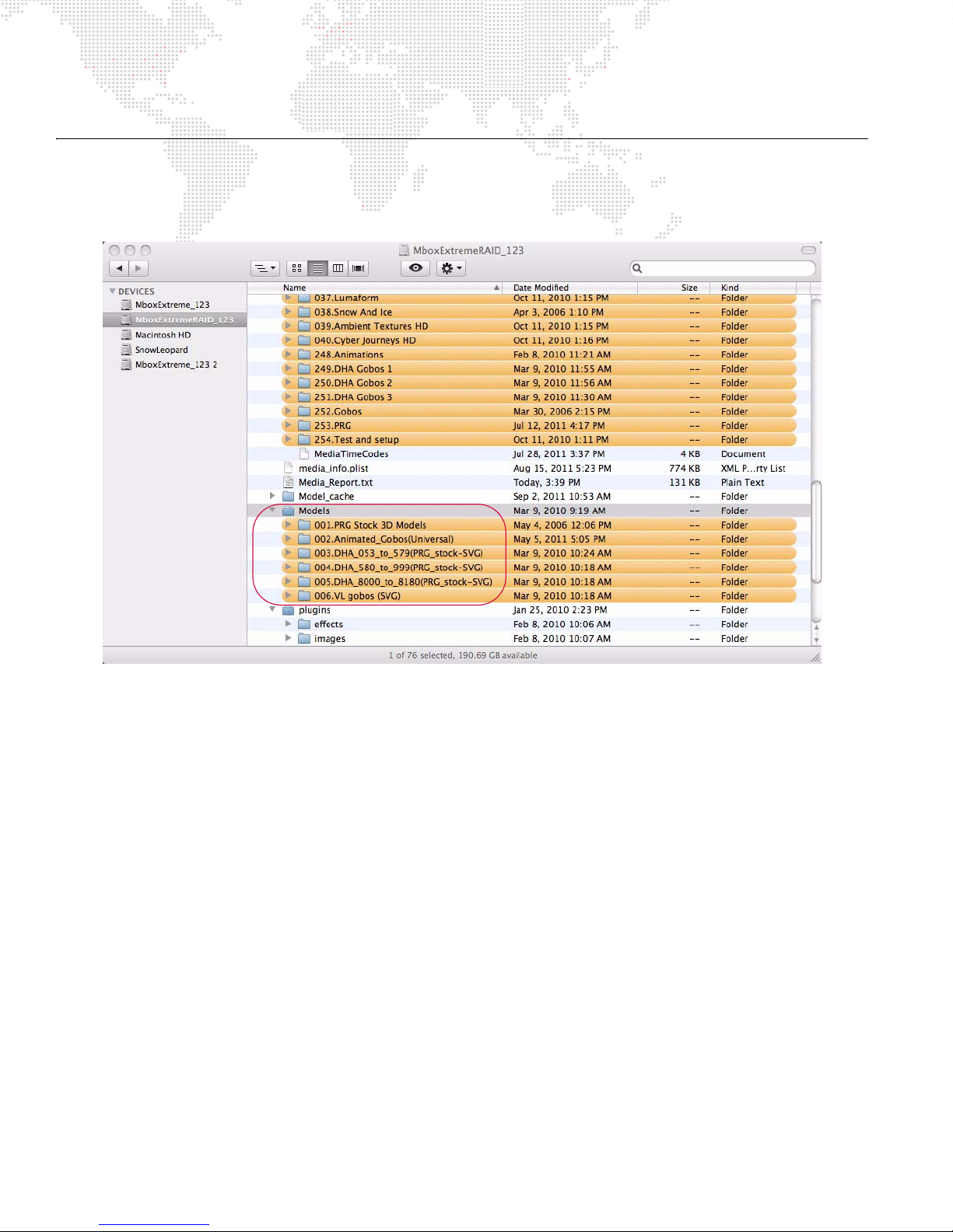
3D OBJECTS AND DIGITAL GOBOS
About 3D Models and Digital Gobos (Objects)
3D Model and Digital Gobo files are arranged into individual folders within the
/Mbox/Models
folder.
Lighting
All 3D models and digital gobos require some amount of lighting to be properly visible. If the object file is used without
turning on one of the Mbox lighting fixtures or without using Drawmode 1 (Light), then the object will appear on the
screen as a black silhouette.
Guidelines:
+ 3D models respond best to the spotlight fixtures. The resulting shadows help enhance the 3D nature of the model.
+ Digital gobos respond best to the ambient light fixture or to Drawmode 1.
Vertex Array Files (Compiling)
When displaying a 3D model or digital gobo file on the screen, that file is read from the hard-drive just like the 2D
content. But loading model and digital gobo files in their original format (.obj, .svg) and converting them to be used
within the Mbox environment can be a slow process. Instead, Mbox Designer generates a new version of these files in
the
Mbox/Models
shorter load times when the files are requested for display. The process of creating the vertex array files is called
"compiling."
folder using a proprietary format. The resulting vertex array files have been optimized to allow for
66 MBOX® MEDIA SERVER USER MANUAL
Page 75

All appropriate files in the
Waiting For Gobot
Models
folder will be compiled automatically the first
time Mbox Designer is started (and successfully locates them). Thereafter, files
in the
Models
folder will only be compiled if they are new or if they have been
modified since the last time Mbox Designer was used. Compiling all of the
stock files in the
Models
folder takes some time, but this task only needs to
happen once in the background, allowing all other functions to be available
during this process. If models or digital gobos that are still waiting to be
compiled are requested, Mbox will display a substitute image until the
requested file has been compiled. If a file that hasn't been compiled yet is
requested, Mbox Designer will display the "Waiting for Gobot" gobo (shown at
right).
Note: If you place a large number of new files in the
Models
folder, don't expect them to be available as soon as the
application launches, but once compiled, the files will be available immediately.
Compiled object files are automatically placed in the
Mbox/model_cache
folder. These files are given a numerical
prefix and the .vtxa (vertex array) suffix. These vertex array files cannot edited or renumbered. Any additions,
deletions, or renumbering of model or digital gobo content should be done in the
model_cache
folder.
Models
folder rather than in the
Preloading 3D Objects
If large, complex 3D models are used, they may not appear on screen as quickly as desired. To assist, Mbox Designer
can be told to preload specific 3D models into system RAM at startup. In order to force a file to preload, either append
".preload" to its filename or to the name of its immediate parent folder - which would cause all of the files in that folder
to be preloaded. Examples:
file - 001.Object.preload.obj folder - 002.LargeObjects.preload
Preloading a large number of objects will cause Mbox Designer to take longer to start up and should only be done if
the models in question do not appear on screen as quickly as desired. When models are preloaded, it is the vertex
array file that is preloaded rather than the original .obj or .vle file. Because of this, preload time is reduced, but could
still be longer than desired.
Normalization
By default, both model and digital gobo files are "normalized" when they are compiled. Mbox Designer's vertex array
compiler performs this task to ensure that the files appear at a usable scale rather than being too large or too small.
Given the wide variety of applications that can be used to create models or digital gobos, an object that appears to be
just right when created might appear to be gigantic or tiny when displayed by Mbox Designer. Different applications
may use different units of scale – pixels, inches, meters – but each of these units of measure will be saved as a
generic unit in an .obj or .svg file.
Therefore, when compiling, Mbox Designer's default action is to normalize all models and digital gobos. Normalization
is accomplished by scaling objects to fit into a bounding cube that is 480
down so that their largest dimension is 480
px and their other dimensions are then scaled proportionally.
px on each side. Objects are scaled up or
To stop the compiler from normalizing an object, the suffix ".noscale" can be added to its name before the file is
compiled and the file will not be normalized when it is compiled. If this option is used, one generic unit will equal 240
pixels in the Mbox 3D environment. Example:
a file named - 001.MyObject.obj should be renamed as - 001.MyObject.noscale.obj
To create an object with a scale factor (relative to other files), use the ".scale" switch. In the following example, the
second file would appear at half the size of the original:
a file named - 023.DigiGobo.svg would be renamed as - 023.DigiGobo.scale_0.50.svg
MBOX® MEDIA SERVER USER MANUAL 67
Page 76
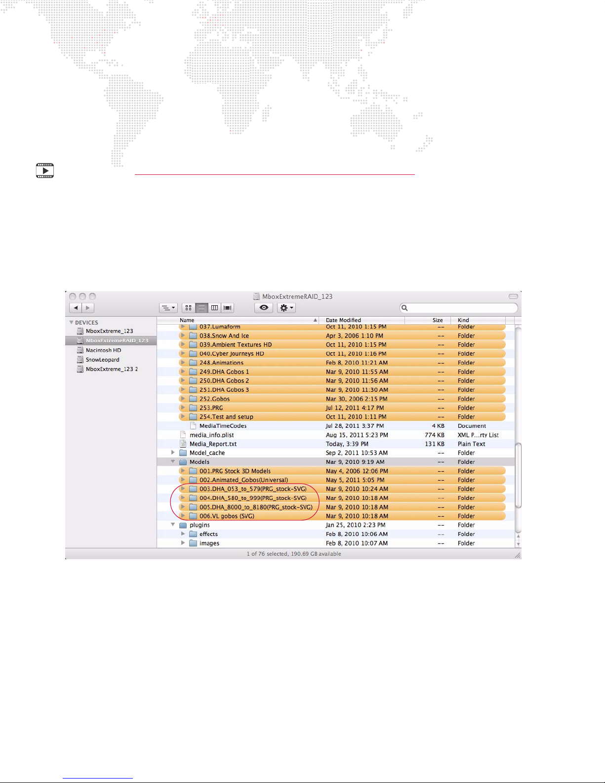
If you create an object that is scaled to match a particular piece of 2D content (which is measured in pixels), and you
want Mbox to treat generic units as pixels, add the suffix ".pixels" to the file's name before it is compiled. Example:
a file named - 001.NewObject.obj should be renamed as - 001.NewObject.pixels.obj
In this case, an object that is 200 generic units tall will appear as 200 pixels tall within Mbox. And a piece of 2D
content that is 200px high would fit exactly when applied to that object.
Training Video: Mbox Media Server Training Video Chapter 18: 3D Functionality
DHA and VARI*LITE Digital Gobos
A selection of DHA and VL gobos are included in the
/Mbox/Models
folder of the rental Mbox Extreme server. These
are "digital gobos," and are treated like 3D models in many regards. There are four folders of gobos (003, 004, 005,
and 006) saved as .svge (Scalable Vector Graphics Encrypted) files. The files are copy-protected using the same
scheme that copy-protects the stock movie content.
68 MBOX® MEDIA SERVER USER MANUAL
Page 77
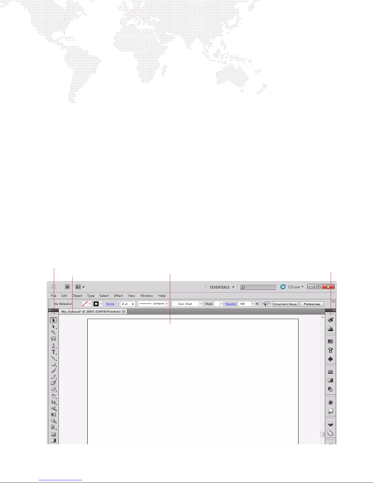
Creating Custom Digital Gobos
Document Name
Artboard
Drawing Tools
Other Tools
Overview
Custom digital gobos can be created in two formats: SVG and AI (Adobe Illustrator®). Adobe Illustrator is the best
application for creating custom digital gobos because it provides the best toolset for features that Mbox Designer
supports. SVG files are the most compatible and they provide better functionality than AI files.
Mbox Designer's vertex array compiler pays attention to "object fill" information in these file types. Path and Stroke
information is ignored, unless special steps are taken with the file. (Refer to the Adobe Illustrator documentation for
more information on path, fill, and stroke.)
Scale-To-Fit vs. Arbitrary Fit
Before beginning, determine the intent of the digital gobo. If you create an SVG gobo file, you have two options for
how a texture is mapped to the digital gobo:
+ Scale To Fit - This will have a texture stretched (or squashed) to fit onto the digital gobo, provided you have a
shape that you want to apply the texture to.
+ Arbitrary Fit - This will have a texture applied to a digital gobo with a specific fill factor given to the texture - if you
are using a digital gobo as a texturable masking aid or if you don't want the texture scaled. If you create an AI
gobo file, you are limited to the Scale To Fit option, and the procedure is slightly different.
Creating a Digital Gobo with Adobe Illustrator CS5
The following steps provide a general guideline for creating custom digital gobos using Adobe Illustrator CS5. Note
that older versions of Illustrator may require slightly different steps to achieve the same results. For more information
regarding the use of Illustrator, consult the Illustrator Help documentation included with the application.
Step 1. Start a new document and name it appropriately. The size of the artboard and orientation of the document
are not critical, nor is the color space (RGB or CMYK). Basically, just make sure the document is large
enough to hold all of the objects.
MBOX® MEDIA SERVER USER MANUAL 69
Page 78
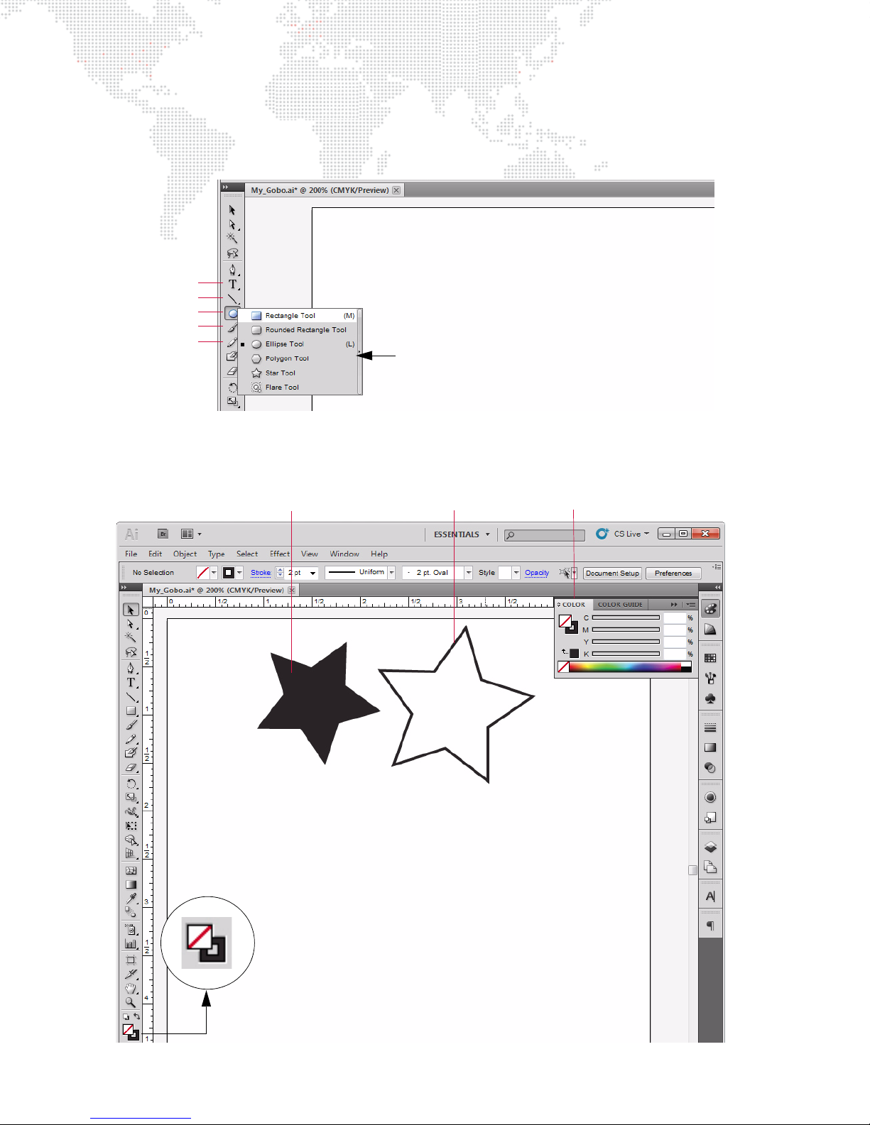
Step 2. Use the various drawing tools to compose the gobo. The most useful tools are the objects (ellipse,
Tool Options
Text
Lines
Objects
Paint Brush
Pencil
Filled Object
Outlined (Stroked) Object
Fill/Stroke Color Options
Fill/Stroke Setting
rectangle, polygon, or star), the paintbrush, the linear tools (line, arc, spiral), text tool, and the pencil. All of
these tools, except the line tool, will create a filled object. Filled objects will be compiled as solid areas in
Mbox and will be the areas that accept a texture, if one is applied.
Step 3. To make an outline of an object, turn off the object's fill and then expand the object. To turn off the fill, select
the object in question and then make sure the Fill/Stroke portion of the toolbar looks like the example
below.
70 MBOX® MEDIA SERVER USER MANUAL
Page 79
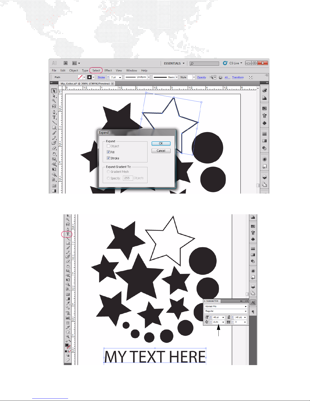
Step 4. To expand an object, first select the object, then choose Expand from the Object menu. This will open a
Character
Options
pop-up window. You don't need to change any of the options in the window, just press OK. Add more
objects as desired. (You can use multiple layers, if required.)
Step 5. Use the text tool to create text as desired. Use the Character options to set font and size.
MBOX® MEDIA SERVER USER MANUAL 71
Page 80
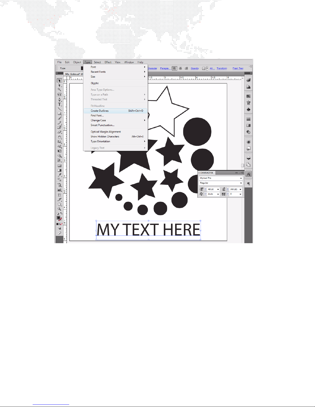
Step 6. Text is a special case, and must be converted out "outlines." Switch to the Selection Tool and select the
text. Select "Type" in the menu bar, and then select "Create Outlines." You cannot make outlined text
(stroke only), it has to be filled.
Step 7. If you are creating an SVG gobo, you need to apply a crop area to the document. The size and location of
this crop area will determine whether your digital gobo will fall under Option 1 or Option 2. The texture
applied to the gobo will fill the crop area when the gobo is used in Mbox. Note: It is not recommended that
the crop area be sized or positioned so that any portion of an object fall outside the crop area.
a. Option 1: If you just want to apply a texture to your gobo so that the texture completely fills the gobo,
then create the crop area so its borders are just outside the edges of all of the objects in your
composition.
b. Option 2: If you have a texture that you do not want scaled (or want scaled to a specific size) and only
want to show that texture in the positive areas of the gobo without any further scaling, then make the
crop area the same as your content and arrange the objects in the file inside that crop area. In this case
the gobo acts as an inverted mask since the result ends up displaying the unscaled texture on the the
positive areas of the SVG file.
If you are creating an AI gobo, you can't use crop areas, and the applied texture will be stretched or
squashed automatically to cover all of the objects in the file. You can use rectangles with no dimensions
(0
px x 0px) to affect how the texture is applied by using them to define the corners of an imaginary crop area.
To add a rectangle with no dimensions, select the rectangle tool and click and release on the drawing area.
In the dialog box that opens, enter 0 for the horizontal and vertical size of the rectangle. You won't be able
to see these objects in Mbox Designer, but they will affect how the texture is applied.
72 MBOX® MEDIA SERVER USER MANUAL
Page 81
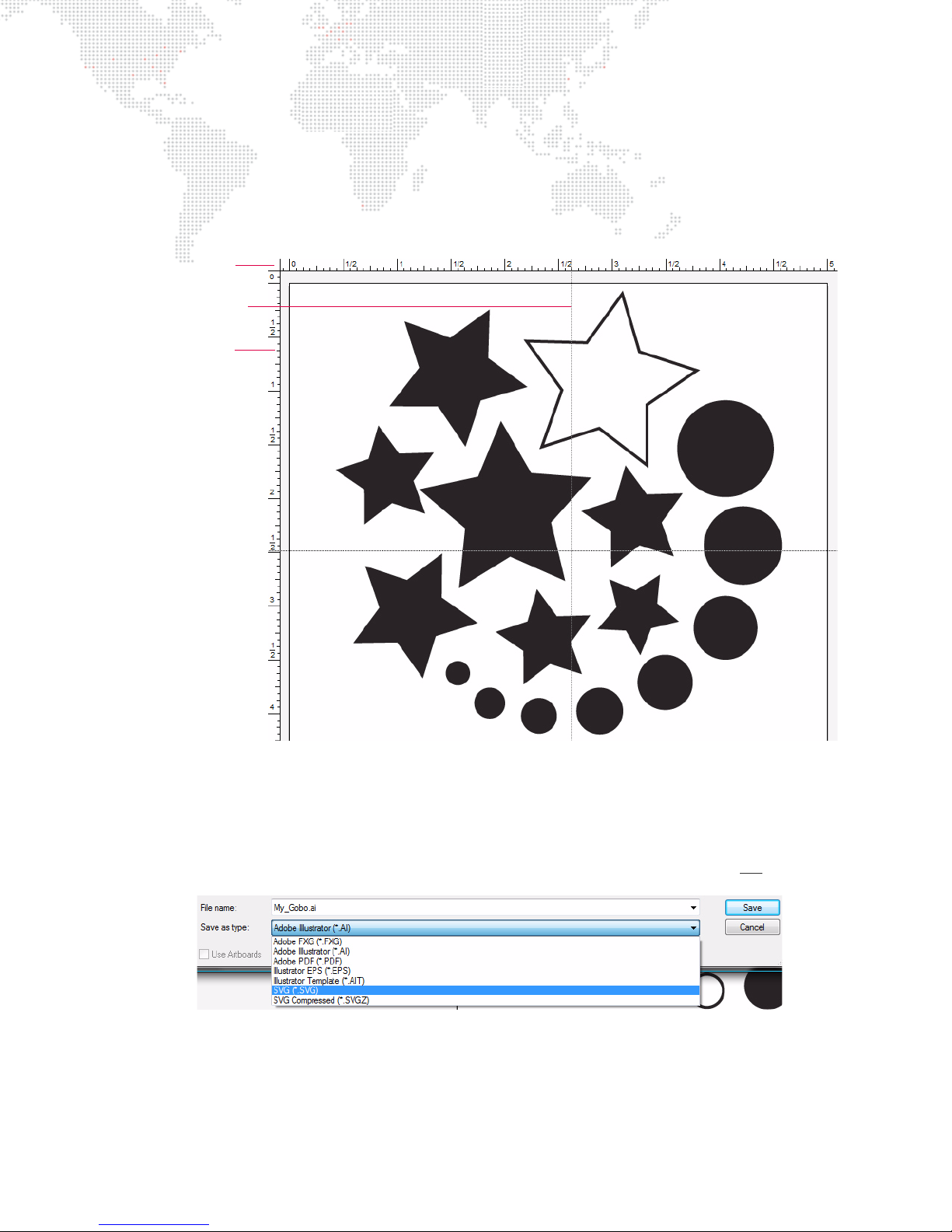
Step 8. Before you saving the file, consider where the center of the file should be. By default, the center of a digital
Drag Crosshairs
from corner
Crosshairs
Ruler
gobo will appear in the center of the Mbox Designer window and the gobo will rotate around that center
point. If you save the file as an AI file, you can set the center by modifying the origin of the file in Illustrator.
To modify the origin of a file, click and hold on the small, dotted set of crosshairs at the top-left of the
document window then drag the crosshairs to where you want the origin to be. For optimal results, the new
origin must be within the boundaries of one of the objects in the file. Note: You must have rulers turned on
to see the origin and crosshairs.
Step 9. Save file, choosing either the SVG or AI format. Both file types will prompt a secondary pop-up window to
Step 10. When creating an SVG file, change the file extension from .svg to .svge to allow Mbox Designer to generate
If you save your file as an SVG file, then the rotational center of the file can either be the center of the crop
area, or you can add a rectangle with no dimensions which then defines an alternate center point. This 0
x 0
px rectangle can be either inside or outside of other objects in the file and inside or outside the crop area.
px
set options when saving the file. When saving as an SVG file, you do not need to modify any of the default
values. When saving as an AI file, you need to make sure that "Use Compression" is not
checked.
thumbnails of the SVG file.
MBOX® MEDIA SERVER USER MANUAL 73
Page 82
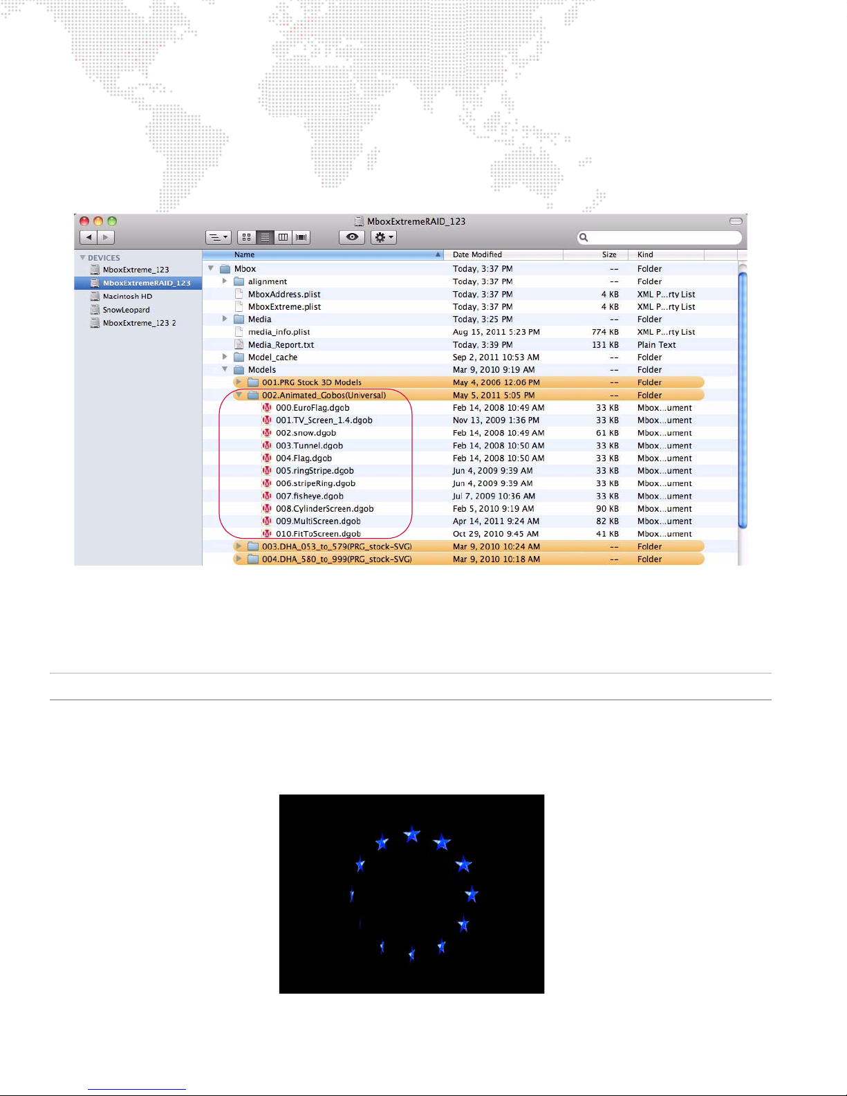
Animated Digital Gobos
Mbox animated gobos are similar to SVG gobos, but they have built-in functions which have their own controls.
Animated gobos, saved as .dgob files, are located in the
digital gobos, these files do not need to be compiled so there will be no corresponding .vtxa files. Like other digital
gobos, the animated gobos are treated as objects and some of them require lighting.
/Mbox/Models/002.Animated_Gobos
folder. Unlike normal
The animated gobos use three channels on the Object fixture: Animation Speed, Animation Modifier A, and Animation
Modifier B.
+ Animation Speed: affects the rate (and in some cases the direction) of the gobos’ motion.
+ Modifiers A & B: manipulate other traits.
For a complete channel map, refer to "Mbox Parameter Descriptions" on page 209.
EuroFlag (002/000)
The EuroFlag animated gobo is very basic. The layer’s texture is applied to each star and the Animation Speed
channel controls the speed at which the stars rotate. The A and B modifiers have no effect.
74 MBOX® MEDIA SERVER USER MANUAL
Page 83
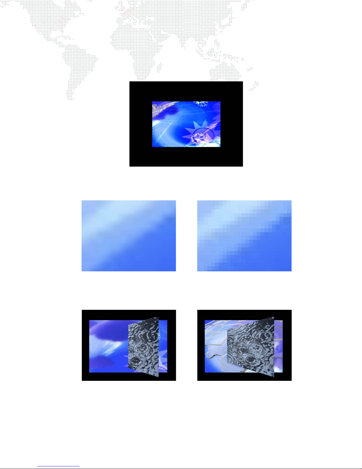
TV Screen v1.4 (002/001)
A mod <= 127 A mod > 127
B mod <= 127 B mod > 127
The TV Screen animated gobo allows a texture to be placed onto a plane in 3D space and manipulated it as a 3D
object. The texture can rotate and spin on all three X, Y, and Z axes. (A texture on its own will only rotate on the Z axis.)
The TV Screen will automatically light itself and Drawmode 1 does not have to be set for it to be visible.
If the A modifier is set above 127, the TV Screen will display a direct pixel-per-pixel representation of the applied
texture rather than an interpolated representation. For better clarity, scale has been greatly increased in the following
example:
If the B modifier is set above 127, the TV Screen will no longer obey the rules of 3D space and will always be
completely in front of a lower-numbered layer, whether it’s a background texture or a 3D object. In the following
example, the foremost layer has been rotated on the Y axis:
MBOX® MEDIA SERVER USER MANUAL 75
Page 84
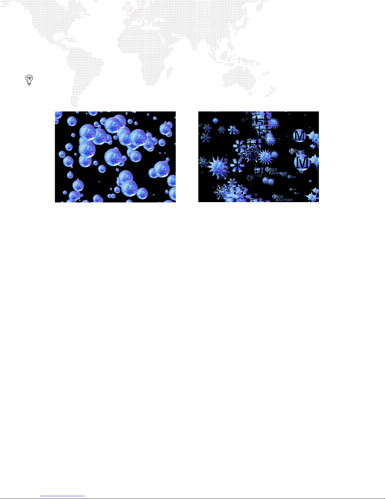
Snow v1.2 (002/002)
000 - default 255 - random
The Snow animated gobo is somewhat complicated. In order to have complex snowflake shapes, a folder named
"snowflakes" must be created within the
.vxta files can be copied from the
In the example below, the left-hand image shows the default (000) snowflake shape: a round flake. The right-hand
image shows several different flake shapes: the shape is set to random (255).
If the shape is set to a particular value between 1 and 254, the corresponding numbered shape from the snowflake
folder will be displayed. If no corresponding shape exists, it will display the default shape.
Mbox
folder and numbered .vtxa files (1 to 254) must be placed into it.
model_cache
folder into the snowflakes folder.
Animation Speed controls the rate at which the snow falls.
+ The A modifier selects the shape of the flakes.
+ The B modifier selects the number of flakes on the screen at one time.
Texture Scale (on the same layer) will affect the size of the flakes and Z-rotation will affect the direction in which the
flakes fall.
76 MBOX® MEDIA SERVER USER MANUAL
Page 85
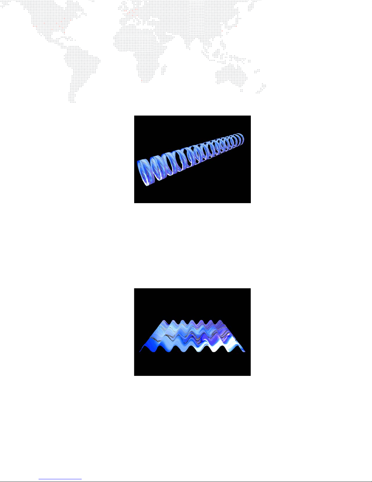
Tunnel v1.1 (002/003)
The Tunnel animated gobo is a virtual tunnel made up of rings. The shape can be rotated.
Animation Speed controls the rate and direction in which the rings move.
+ The A modifier controls the number of rings.
+ The B modifier controls the thickness of the rings.
In the following example, the X and Y rotation has been adjusted so that the shape can be seen more clearly. The
Tunnel’s default position is directly head-on to the camera.
Flag v1.0 (002/004)
The Flag animated gobo is a virtual flag, which can be rotated.
Animation Speed controls the rate and direction of the ripples.
+ The A modifier sets the amplitude of the ripples.
+ The B modifier sets the number of ripples.
In the following example, the X rotation has been adjusted so that the shape can be seen more clearly.
MBOX® MEDIA SERVER USER MANUAL 77
Page 86
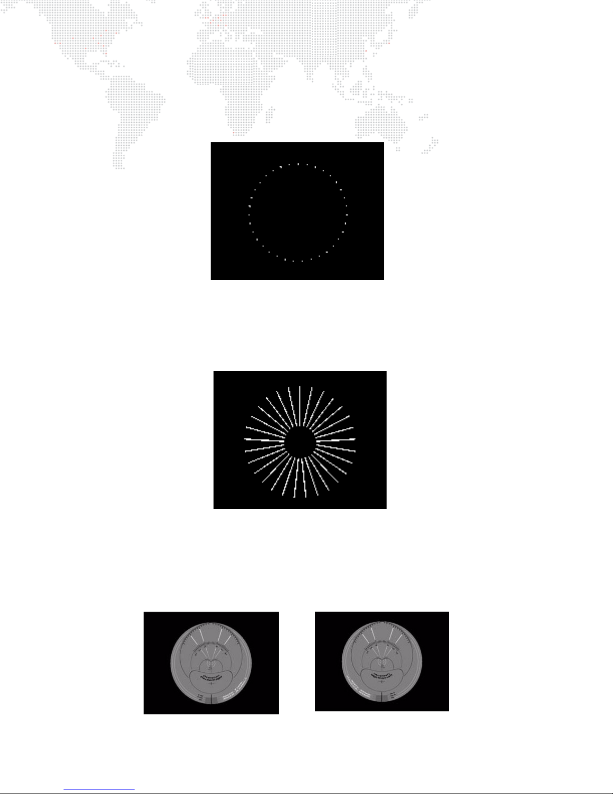
Ring Stripe (002/005)
fisheye fisheye mirrored
For the Ring Stripe animated gobo, Animation Speed controls the scale.
+ The A modifier sets the segment thickness.
+ The B modifier sets the number of segments (= value +1).
Stripe Ring (002/006)
For the Stripe Ring animated gobo, Animation Speed controls the central diameter.
+ The A modifier sets the line thickness.
+ The B modifier sets the number of lines (= value +1).
Fisheye (002/007)
For the Fisheye animated gobo, Animation Speed controls the seam blending and mirroring (0-126 = mirrored, 127 –
255 = normal).
+ The A modifier sets the push from center.
+ The B modifier sets the push from edge.
78 MBOX® MEDIA SERVER USER MANUAL
Page 87
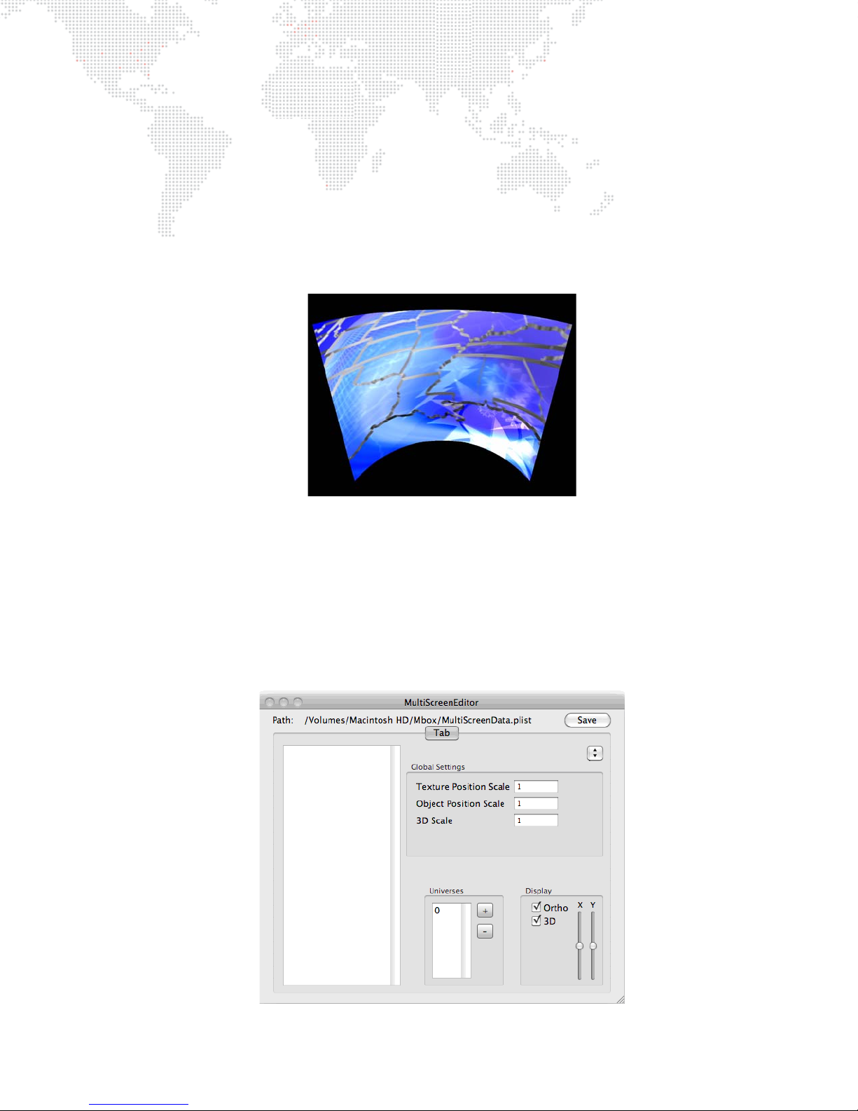
CylinderScreen (002/008)
The Cylinder Screen animated gobo provides a similar surface to the TV Screen gobo that can also bend around its Yaxis.
Animation speed (default = 127) controls the amount of the curved surface that is covered by the texture applied to
the layer. Adjusting this control makes it look like the texture is being scaled up and down, however, notice that the
apparent curvature of the texture changes as it fills more of the curved surface.
+ The A modifier (default = 127) controls the radius of the curve of the screen and the direction of the curve.
+ The B modifier (default = 127) controls the rotation of the screen around its own Y-axis (rather than around the
global Y axis of the Mbox 3D environment).
MultiScreen Gobo (002/009)
The MultiScreen animated gobo is used with the Mbox Pixel Remapping features to allow placement of content onto
a predefined structure that can receive external data (Art-Net) to control both the position and arrangement of the
content on the structure, and also the structure’s position in 2D and 3D space. The MultiScreen gobo is intended for
use with complicated or creative video arrangements that require pixel remapping, or that involve motion (scenic
tracking) during playback. A MultiScreen Editor provides the toolset for creating and editing the MultiScreen.plist file,
which the MultiScreen animated gobo uses as its instruction set. For complete instructions on using the MultiScreen
Gobo, refer to the "Pixel Remapping" chapter on page 119.
MBOX® MEDIA SERVER USER MANUAL 79
Page 88
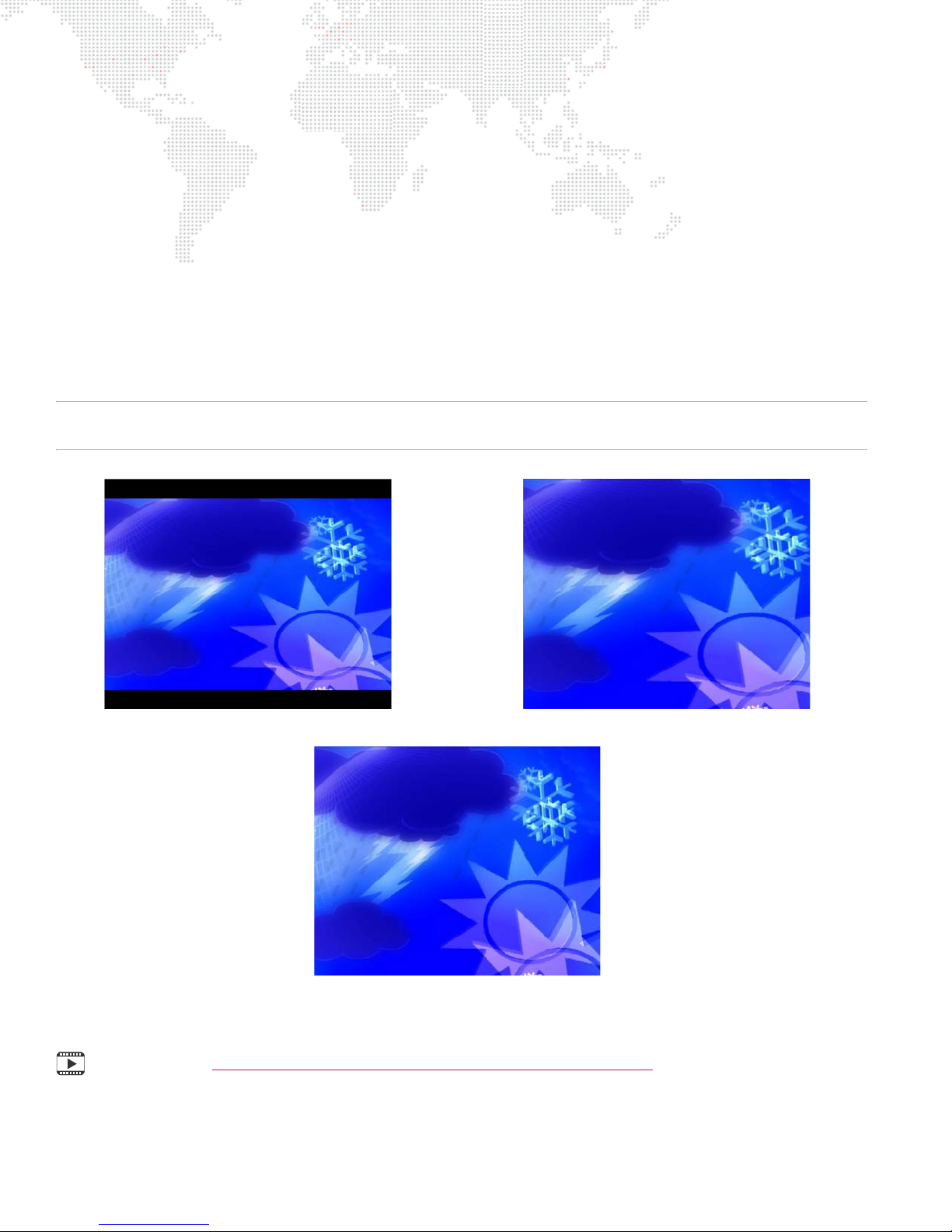
Fit To Screen (002/010)
Horizontal
Vertical
Horizontal and Vertical
The Fit To Screen animated gobo can be used to force any content to fill the screen in one of three ways: Horizontal,
Vertical, Horizontal & Vertical. The layer's scale parameter must be at their default values for the fill to work correctly.
The FIt To Screen gobo requires no lighting.
The A modifier selects the fill mode:
+ 0 - 63: Image is scaled so both width and height are >= screen size (i.e. the smaller dimension is scaled to fill, so
the larger dimension overfills the screen and is cropped). The image aspect ratio is not affected.
+ 64 - 127: Image is scaled so height = screen size (image width may be bigger or smaller than the screen width).
The image aspect ratio is not affected.
+ 128 - 191: Image is scaled so width = screen size (image height may be bigger or smaller than the screen height).
The image aspect ratio is not affected.
+ 192 - 255: Image is scaled in both X and Y so width and height = screen width and height exactly. In this case, the
image aspect ratio will probably change.
Note: Depending on the aspect ratio of the screen vs. the content, the range of 0-63 may look the same as either
64-127 or 128-191.
Training Video: Mbox Media Server Training Video Chapter 18: 3D Functionality
80 MBOX® MEDIA SERVER USER MANUAL
Page 89
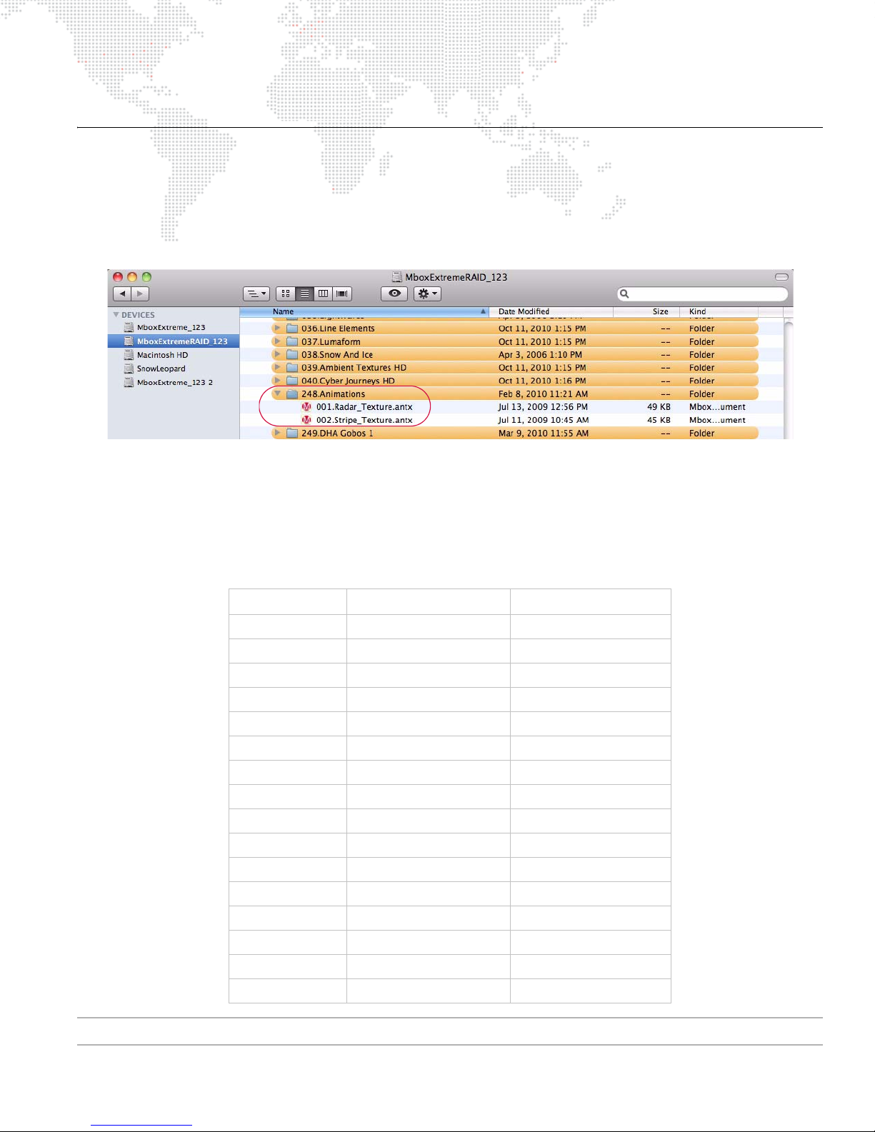
ANIMATED TEXTURES
Using Animated Textures (Animations)
Animated Textures are found in folder 248 of the
Media
folder. They are similar to the Animated Gobos in the
Models
folder, but are controlled differently and cannot have a texture (movie, still image, etc.) applied to them. Each animated
texture has white areas and transparent areas. The white areas can be colored using the RGB controls on the layer.
The layer’s movie playback controls are retasked to set the parameters for the animation – speed, direction, etc.
Playback Controls:
+ In Point – thickness of objects (lines, rays, etc.). A value of 0 gives a default thickness.
+ Out Point - number of objects. A value of 65535 gives a default number of objects.
+ PlaySpeed - speed and direction control. A value of 127 equals no movement.
+ Frame Blending - decay. A value of 0 equals no decay, 255 is full decay.
+ PlayMode – see chart below.
PlayMode Radar_Texture (248.001) Stripe_Texture (248.002)
FWD Loop Sweep Left-Right scroll
REV Loop Bounce Bounce
FWD Once Once Once
REV Once Scrub Scrub
FWD Bounce Mirrored sweep Top-Bottom scroll
REV Bounce Bounce Bounce
Random Once Once
FWD IPR Scrub Scrub
Scrub In Mirrored fan Mirrored L-R
Scrub Out Bounce Bounce
FWD Loop XF Once Once
Rev Loop XF Scrub Scrub
FWD Loop IPR n/a Mirrored T-B
Timecode sync n/a Bounce
Layer Slave n/a Once
Layer Master n/a Scrub
For a complete channel map, refer to "Play Mode" on page 215.
MBOX® MEDIA SERVER USER MANUAL 81
Page 90

LAYER COPY
Using Layer Copy
At times, there may be a need to play the same movie content on more than one layer at the same time. The same
content can be requested on multiple layers, but doing so causes the content to be read from the hard-drive more
than once, as well as being decompressed more than once. This is a waste of resources if you intend to display the
same frame of the same movie on multiple layers at the same time. The Layer Copy function provides a way to copy
the content from one layer to another and to receive the source layer’s effects and transitions, or to ignore the source
layer’s effects and transitions.
There are three modes of Layer Copy: FX-, FX+, and Raw.
+ FX- is a layer copy where the source layer sends its effects and transitions to the destination layer. The destination
layer cannot add more effects via its own controls.
+ FX+ is a layer copy where the source layer sends its effects and transitions to the destination layer. The
destination layer can add more effects via its own controls (allowing up to four effects to be visible on a
destination layer).
+ Raw is a layer copy where the source layer does not send its effects or transitions to the destination layer. The
destination layer can add more effects via its own controls.
Layer Copy functionality is selected as if it were a piece of content in the media folder. Folder 255 is selected, and the
file number attribute controls which layer is being copied and which mode of copying takes place.
Folder 255 /
File #
101 - 112 FX- 1 - 12
121 - 132 FX+ 1 - 12
141 - 152 Raw 1 - 12
Mode Layers Note
File numbers 101-112 correspond to the FX- mode for Layers 1-12.
i.e. 101 = Layer 1 FX- copy mode, 102 = Layer 2 FX- copy mode, and so on.
File numbers 121-132 correspond to the FX+ mode for Layers 1-12.
i.e. 121 = Layer 1 FX+ copy mode, 122 = Layer 2 FX+ copy mode, and so on.
File numbers 141-152 correspond to the Raw mode for Layers 1-12.
i.e. 141 = Layer 1 Raw copy mode, 142 = Layer 2 Raw copy mode, and so on.
Guidelines:
+ Layer Copy does not work with transition 255 (Object Dissolve).
+ When using the Raw copy mode, if a source layer makes a timed transition, then any destination layers using that
source will not receive the transition. Their content will change immediately.
+ A layer cannot copy another layer that is already copying a third layer.
82 MBOX® MEDIA SERVER USER MANUAL
Page 91
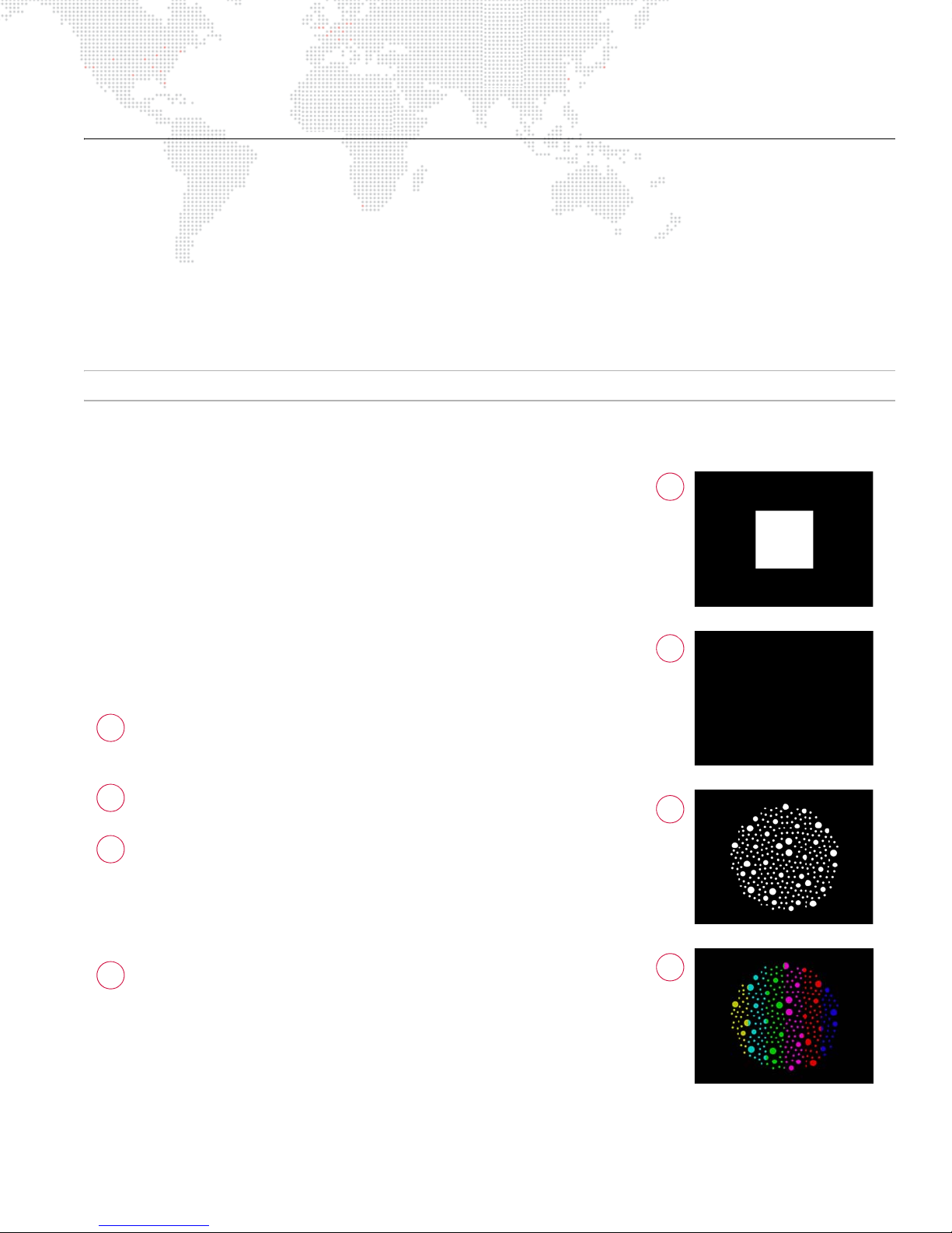
DRAWMODES
1
2
3
4
123
4
Using Drawmodes
The Drawmodes feature provides control over how a 3D object is lit and how it interacts with other layers. Drawmode
has its own control channel with several modes:
+ 0 = Idle
+ 1 = Light
+ 2 = Cut Stencil
+ 3 = Cut plus Light
+ 4 = Cut and Draw
+ 5 = Cut, Draw plus Light
+ 6 = Draw Thru Stencil
+ 7 = Draw Thru plus Light
+ 8 = Draw Onto Stencil
+ 9 = Draw Onto plus Light
+ 16 = Orthographic View
For a complete channel map, refer to "Draw Mode" on page 216.
Drawmodes 0-9 listed above can be used in various combinations with the Orthographic mode (page 84) and the
Layer Blending mode (page 88) to achieve the desired result.
For example, to have a layer use Orthographic drawmode, cut the
stencil, and then use Subtractive Layer blend mode to add the three
values together to get the value for the Drawmode channel:
16 (Orthographic) + 2 (Cut Stencil) + 128 (Subtractive Blend) = 146
Example:
Mode 1, Light, automatically raises the ambient lighting level to 100%
for the selected layer only. This control works with both gobos and 3D
objects and enables objects (and their applied textures) to be seen
without affecting the lighting on other layers.
To achieve the results shown in the images to the right, do the
following:
Set the Camera intensity to 100% and then, on Layer 1 only,
with all other attributes set to default values, set the opacity
to 100%. (You should see a white square.)
With Layer 1 still selected, choose object folder 3, file 0. (The
screen should be black - you cannot see anything.)
At Drawmode control, change from 0 to 1. The gobo should
now be visible. Feel free to experiment with the gobo at this
point. Because it is essentially a 3D object (but with no
thickness on the Z axis), you can do pretty much everything
to it that you can do to a 3D object: scale, rotation, spin, and
X/Y/Z position. Most importantly, you can apply a texture.
Image 4 is the same gobo with a texture applied. In this
case, it is acting like a mask; the texture is applied onto the
gobo, but it appears you’re looking through the gobo to a
layer behind it. However, you’re only using one layer not two.
You can set the Drawmode back to 0 and try out the other
lighting fixtures to see how they affect the gobo.
MBOX® MEDIA SERVER USER MANUAL 83
Page 92
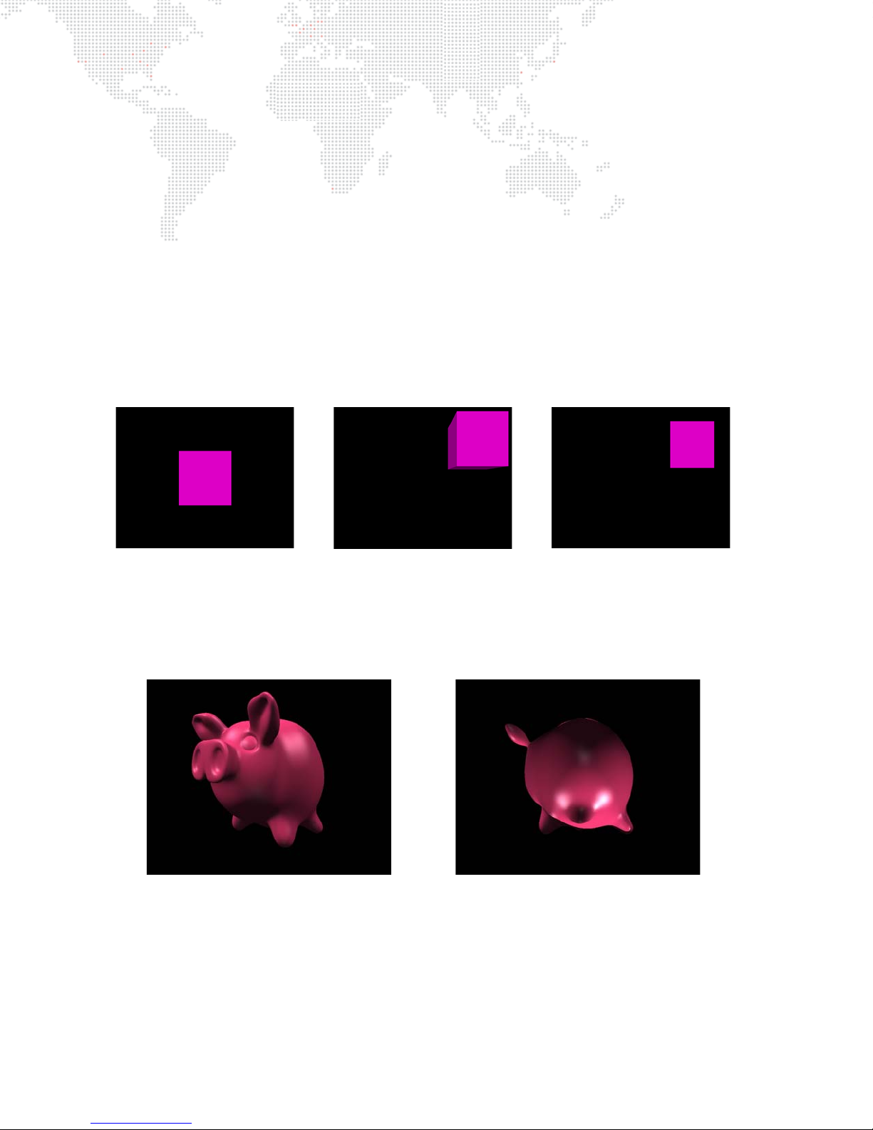
Drawmode 16 - Orthographic View
A cube from the front, centered on
the screen
The same cube positioned off the
center axis. Note the perspective
shift.
The cube, off axis using Drawmode
16. Note that the cube appears to
be smaller. This is because the
section is taken through the center
of the object.
a pig using Drawmode 0 the same pig using Drawmode 16
(not useful)
Drawmode 16 causes 3D objects to be drawn using orthographic projection. Typically, when 3D objects are drawn in
Mbox, they all share one vanishing point, which is a fixed point at the center of the screen (assuming the camera is in
its default position). Because of this, any object that has depth will show some amount of perspective shift as it is
moved around the screen or as the camera moves. If the object is being used as a mask or to simulate a shifting piece
of scenery, then the perspective shift within Mbox may not match that of the actual object. This situation may arise
when using a projector. The degree to which the perspective shift causes issues will depend on many factors
including the type of projector used, the throw distance of the projector, the type of lens used, the amount of
movement of the object, and the object's depth.
To eliminate the perspective shift, command Mbox to draw an object using an orthographic projection mode. This will
cause the object to be drawn so that its vanishing point is always directly behind the object, no matter the position of
the object or the camera. In order to properly scale the object, this drawmode causes a section to be taken through
the object's center of depth. Due to the constraints of the modeling process, this mode only works well with rectilinear
objects which have one major face perpendicular to the camera.
The following illustration show an example of Drawmode 16:
The following illustration shows an example of when Drawmode 16 is not very useful:
84 MBOX® MEDIA SERVER USER MANUAL
Page 93
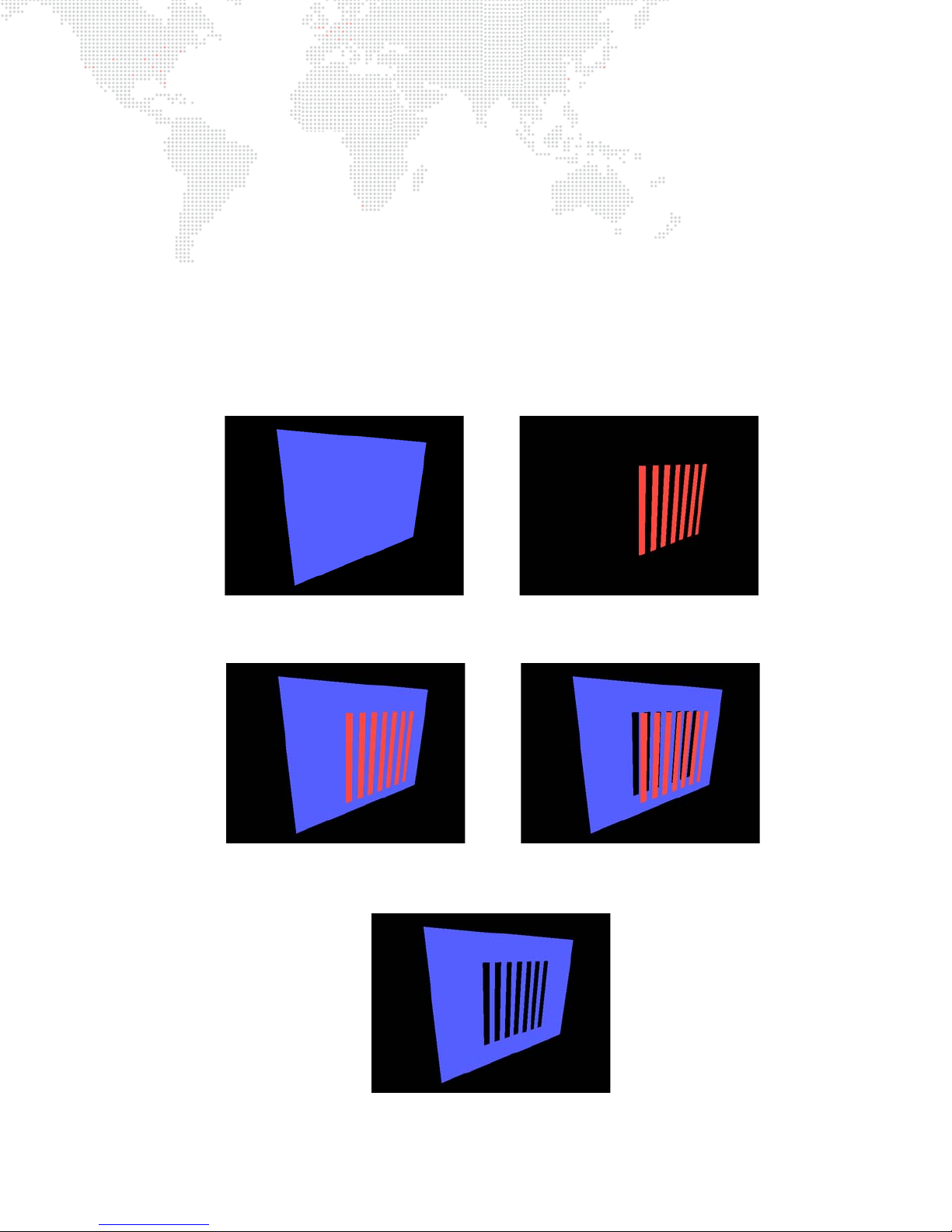
The Stencil
To explain the Drawmodes other than "Light" requires an explanation of the "Stencil" and what it means to cut it, draw
onto it and draw through it. The Stencil is an imaginary layer that can be cut, as if cutting holes in a piece of paper. The
Stencil can then be used as a tool to tell other layers how their textures are applied: either onto the areas where the
stencil is whole or the areas where the Stencil has holes in it.
There are two important things to note:
1) When using a layer to cut the Stencil, the holes that it makes in the Stencil will only affect higher numbered layers.
For example, if Layer 3 is used to cut the stencil, that cut will not affect Layer 1 or 2 no matter what Drawmode
they are set to.
2) For useful results, the layer used to cut the Stencil must have some transparency. In this case, use a 3D object or
gobo or apply a texture effect to the texture on that layer to give it transparency in some areas. If using an
unaltered rectangular image or movie clip to cut the Stencil, it will only create a rectangular hole in the Stencil.
The following example shows a blue rectangle that represents the Stencil and a red gobo that will cut the Stencil:
The following example first shows the two together and then shows the holes being cut into the Stencil by the gobo:
Finally, the following example shows the Stencil on its own showing the holes cut into it:
MBOX® MEDIA SERVER USER MANUAL 85
Page 94
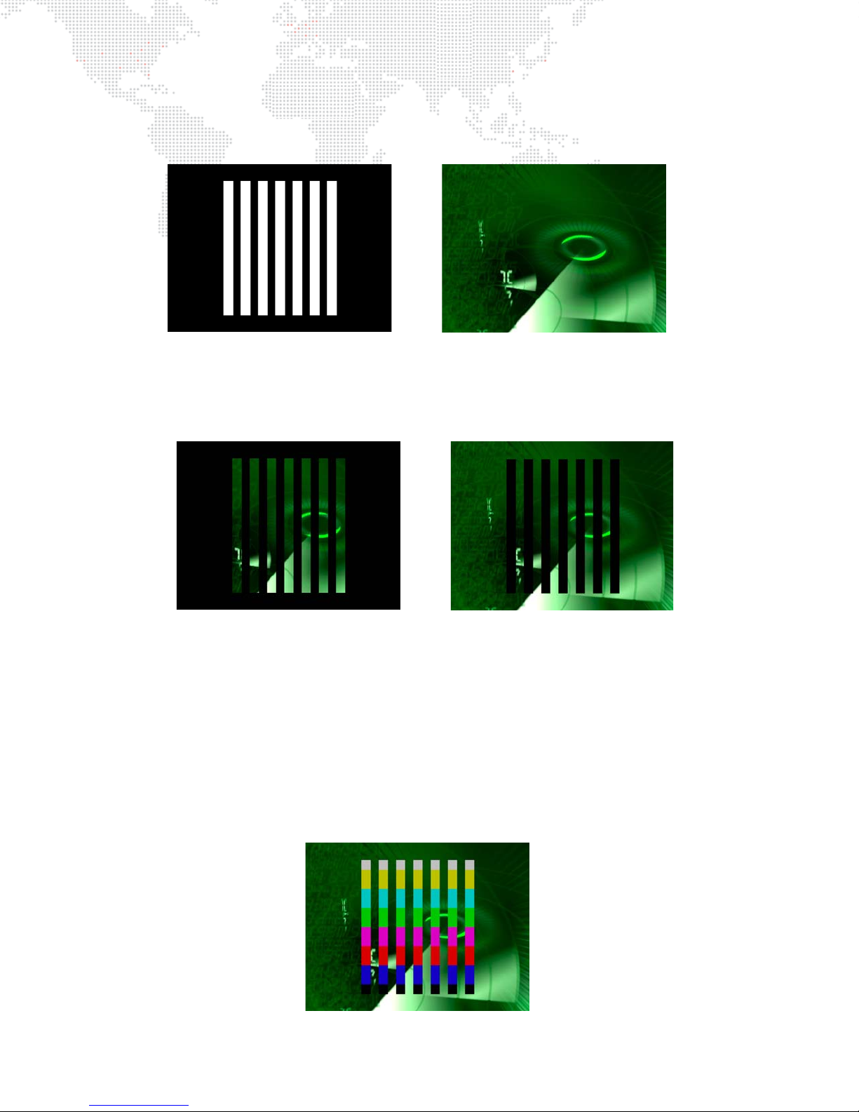
The following shows an example of using the Stencil to affect a higher numbered layer. The left image shows a digital
draw thru stencil draw onto stencil
gobo on Layer 1 in Drawmode 1 (Light) so that it can be seen. The right image shows a movie clip on Layer 2 in
Drawmode 0 (idle). The movie on Layer 2 obscures the gobo on Layer 1.
In the example below, on the left, Layer 2 has been set to Drawmode 6 (Draw thru Stencil) and on the right it has been
set to Drawmode 8 (Draw onto Stencil). In both cases, the gobo on Layer 1 has been set to Drawmode 2 (Cut)
otherwise it would not have any effect upon the Stencil. Note that the lighting on the gobo is off, since the Drawmode
has been changed.
It is important to realize that when a layer’s Drawmode is set to 6, the term "Draw thru Stencil" really means: draw this
layer’s texture only where the holes are in the Stencil. In the opposite case, if a layer’s Drawmode is set to 8, the term
"Draw onto Stencil" really means: draw this layer’s texture only where the Stencil does not have holes.
By setting Layer 1 to Drawmode 5 (Cut and Draw plus Light) and applying a texture to Layer 1, Layer 1’s texture can
be shown instead of the black areas seen in the right-hand image above.
In the example below, Drawmode 5 causes the shape of Layer 1’s gobo to be cut into the Stencil. Also, Layer 1’s
texture is applied to the gobo and, therefore, that texture is shown in the holes in the Stencil. In this particular
example, the same result could be achieved without using Drawmodes by placing the green clip on Layer 1 and
placing the textured gobo on Layer 2 with Layer 1’s Drawmode set to 1.
86 MBOX® MEDIA SERVER USER MANUAL
Page 95
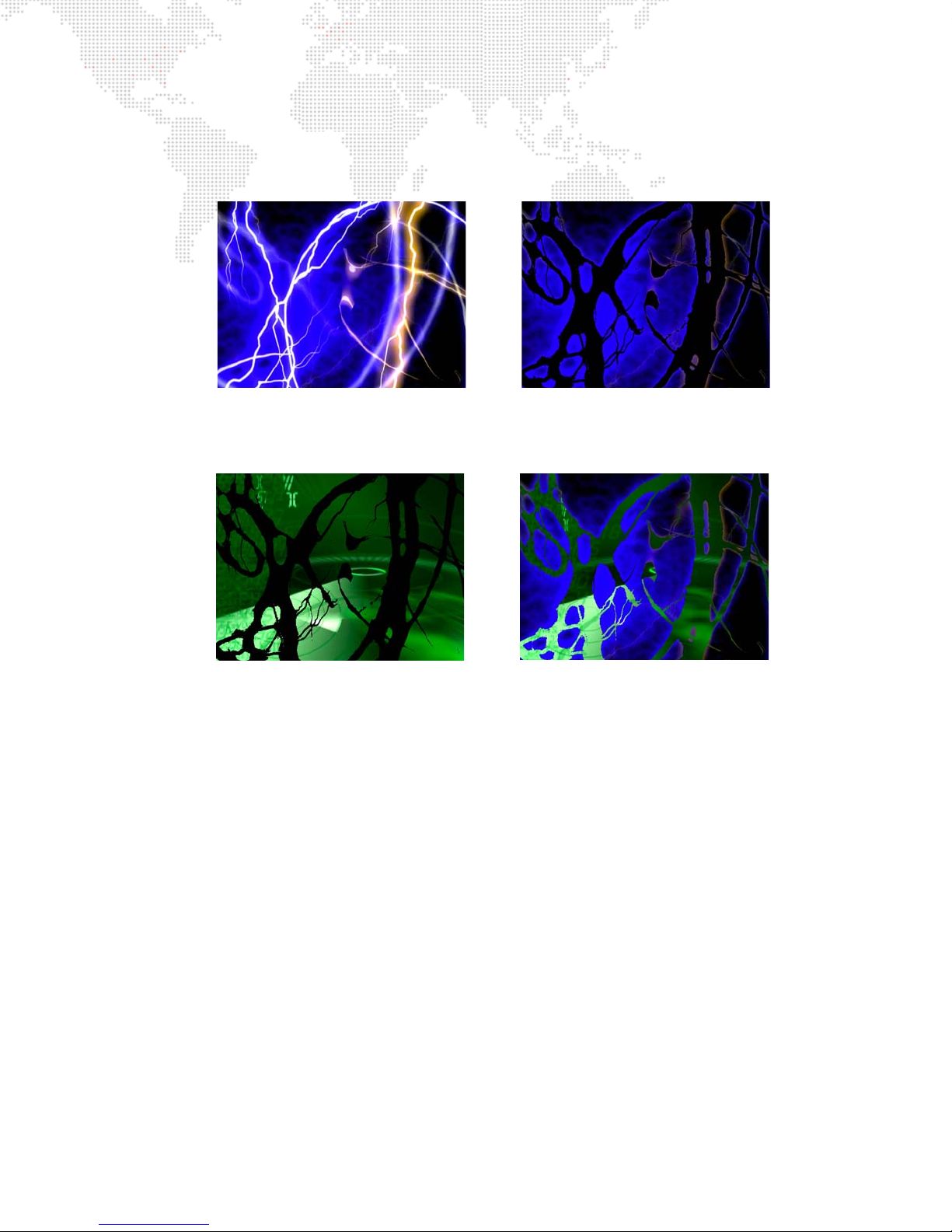
The benefits of the various Drawmodes become more apparent when the holes cut into the Stencil are used to affect
draw thru stencil draw onto stencil
more than one layer. Interesting results can be achieved by using a movie with a transparency effect to cut the Stencil.
In the example below, the left-hand image shows a movie playing on Layer 1, and on the right, that same movie with
the White Alpha Effect (056) turned on.
In the following example, Layer 1 is using Drawmode 5 and a movie is placed on Layer 2, shown with Drawmode 6 on
the left and then with Drawmode 8 on the right.
MBOX® MEDIA SERVER USER MANUAL 87
Page 96
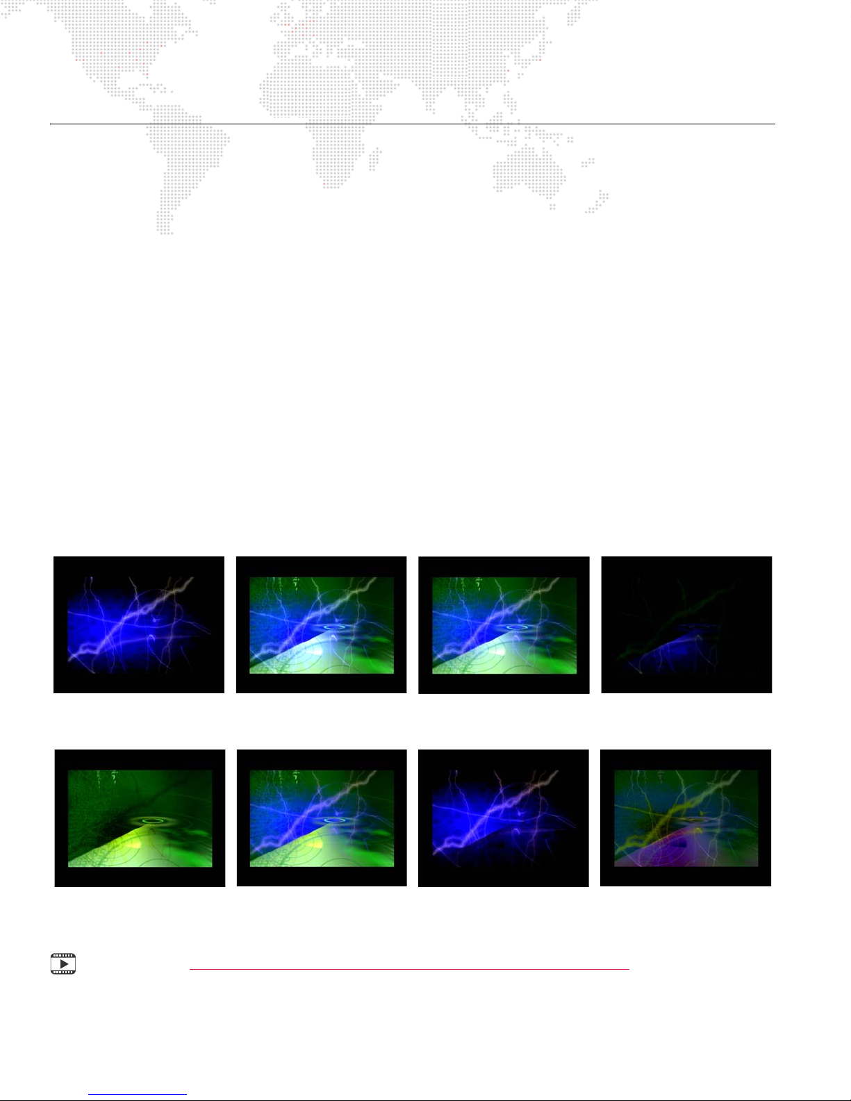
LAYER BLENDING
Overlay (default) Additive Screen Multiply
Subtractive Exclusion Invert Subtractive Invert Additive
Layer Blending Modes
There are seven layer blending modes. Many of these layer blending modes have been chosen to best replicate
common modes found in commercial image editing software (e.g. PhotoShop®, After Effects®
values are:
+ 32 - Additive: layer’s colors are added to underlying colors (blacks appear transparent).
+ 64 - Screen: similar to above, with less of underlying color (blacks appear transparent).
+ 96 - Multiply: multiplies a layer’s color with underlying color (blacks appear opaque).
+ 128 - Subtractive: layer’s colors are subtracted from underlying colors (blacks appear transparent).
+ 160 - Exclusion: underlying colors are inverted where layer color is lighter; layer’s colors are then added to
underlying colors (blacks appear transparent).
+ 192 - Invert Subtractive: underlying colors are subtracted from layer’s colors (blacks appear opaque).
+ 224 - Invert Additive: layer’s colors are inverted and are added to inverse of underlying colors (blacks appear
transparent).
The blending modes are accessed using the Drawmode control on each layer. Their discrete values have been
structured so that the pre-existing drawmode controls can still be used in combination with the new blend modes. As
noted in "Using Drawmodes" on page 83, the Drawmode control uses values between 1 and 31 to select
combinations of functionality. These original values can be added to the blend mode values noted above to in order to
combine the functions. For example, Drawmode "Draw thru stencil" has a value of 6. Blend Mode Exclusion has a
value of 128. To use these two items together, set the drawmode channel to a value of 6 + 128 = 134.
). The modes and their
Training Video: Mbox Media Server Training Video Chapter 10: Media Server Concepts
88 MBOX® MEDIA SERVER USER MANUAL
Page 97
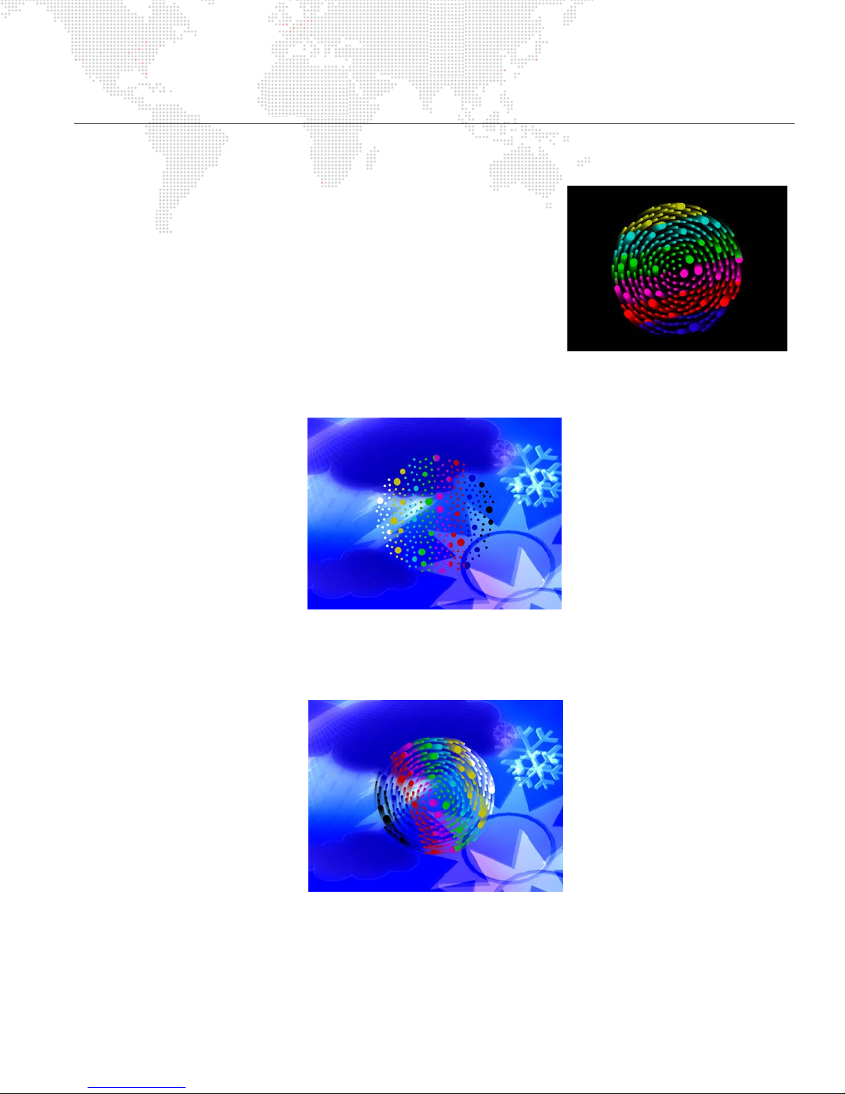
SPECIAL EFFECTS
Decay
The Camera fixture includes controls for a Delay effect. Since it operates
from the Camera fixture, the decay is applied to the composite image
created by all five layers.
In the example to the right, a gobo has been given a Z-spin value and
decay has been applied.
It is important to note that Decay will only work against a background of
"nothingness." This means the absence of content (no texture or object). If
no layer is above 0% opacity, then there is only black "nothingness" (i.e.,
the absence of content). If a gobo is placed on Layer 1 and a texture is
applied, then rotate or move it with decay turned on, to see the effect.
If a gobo is placed on Layer 2, in front of a fullscreen texture on Layer 1, and then decay is turned on, no decay will be
seen.
You cannot tell that the gobo is rotating from the example image here, but it is. But no decay is visible since there is
"nothingness" behind it. However, if you reduce the opacity of Layer 1 behind the gobo, you can begin to see the
decay.
MBOX® MEDIA SERVER USER MANUAL 89
Page 98
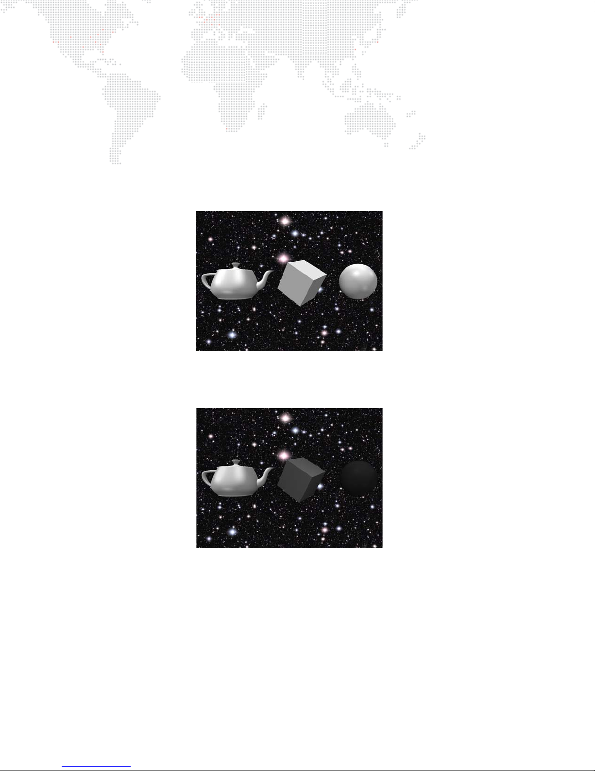
Fog
The Camera fixture also includes control for the Fog effect. Like Decay, it works on the composite picture created by
all five layers. However, fog only has an effect on 3D objects (or digital gobos) if they have been lit. The objects can be
lit by the Ambient fixture, any of the four Spot fixtures, or by having their Drawmode set to one of the modes that
includes lighting. The Fog effect causes objects that are further from the camera to be dimmer (harder to see) than
objects that are closer to the camera.
In the example below, there are three objects all at different distances from the camera (their Z-Position has been
modified). The teapot is closest, followed by the cube, and then the sphere. Since they all use the same lighting
created by the four spot fixtures, and they have been scaled and arranged so that they all appear to be roughly the
same size, they look as if they are all the same distance from the camera:
In the image below, the Fog effect has been turned on. Now the differences in the Z-position (distance from the
camera) can be seen. The object furthest from the camera is darkest.
90 MBOX® MEDIA SERVER USER MANUAL
Page 99

TEXT FILES
Support for Text Files
Mbox can display text using RTF (Rich Text Format) or TXT (Text) files. Both files will work, but the RTF format will
result in higher quality.
.rtf
An RTF file can be created by using the TextEdit application on the Mac computer. Simply type some text into a
document and then save as an RTF file. Be sure to give the document a numerical prefix, make sure it has a file
extension of .rtf, and place it in the
Guidelines for RTF files:
+ Do not use multiple fonts on the same line of text.
+ Keep font sizes large.
+ Justification in the document is ignored; use spaces in the text instead.
+ Font color is taken into account. For best results, make text white rather than black.
.txt
A text file can also be created using the TextEdit application. In this case, save as a .txt file. Be sure to give the
document a numerical prefix and place it in the
Guidelines for TXT files:
+ Text quality is quite low in comparison to that of RTF files.
+ The .txt format does not allow for text sizing or custom fonts.
+ If there is more than one line of text in the file, Mbox will "play" the file line by line.
+ Adjusting play speed will cause the file to play faster or slower.
Media
folder.
Media
folder.
MBOX® MEDIA SERVER USER MANUAL 91
Page 100
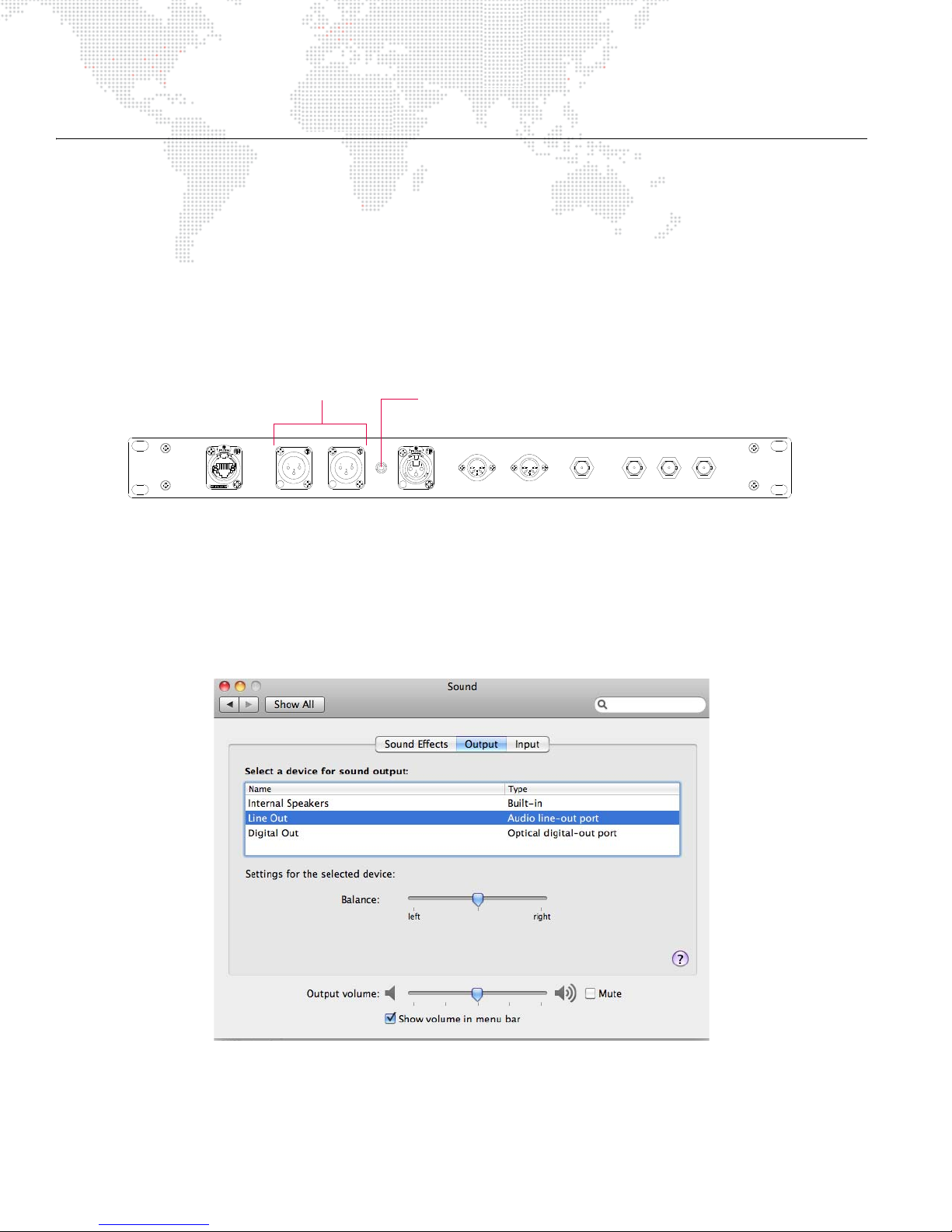
AUDIO
BALANCED AUDIO OUT
RIGHT
MIDI IN
(COMPOSITE)
Y IN
SDI IN R-Y IN B-Y IN
ETHERNET LEFT
MIDI OUT
SMPTE IN
Balanced XLR Audio Out
(Left and Right)
Unbalanced Mini Plug Audio Out
(3.5mm Mini Jack)
Audio Output Features
Overview
In addition to movies, still images, and 3D objects, Mbox can also play audio files. Audio can be played back by any
of the following methods:
+ The Mac computer’s internal speaker.
+ The Mac computer’s SPDIF audio jack.
+ The XLR connectors (for balanced output) or 3.5mm jack (for unbalanced output) on the Auxiliary panel.
Figure 4-1: Auxiliary Input Panel (v3.4)
Selecting an Output Device
In order for sound to play, the appropriate audio output device must be selected in the Mac's Sound Preference
window. (To use the XLR or 3.5mm connectors on the Auxiliary Input panel, choose the Mac’s Line Out output.) The
balance and volume may also be adjusted at the Sound window.
92 MBOX® MEDIA SERVER USER MANUAL
 Loading...