

Page 1
Bullet Series 2.0 LED Luminaire
QUICK START GUIDE
This document provides installation and setup procedures for the PRG Bullet Series
2.0 LED Luminaire.
For complete operating instructions, refer to the Bullet Series 2.0 LED Luminaire User
Manual available at www.prg.com
For technical assistance, contact PRG RH+A.
PRG RH+A
539 Temple Hill Road
New Windsor, NY 12553-5533
1-800-748-6562
www.prg.com
1. IMPORTANT SAFETY INSTRUCTIONS
+ Keep these instructions.
+ Heed all warnings.
+ Follow all instructions.
+ Do not block any of the fixture’s ventilation openings.
+ Do not operate at temperatures above 40°C (104°F).
+ Do not install the fixture near any heat sources such as radiators, heat registers,
stoves, or other apparatus (including amplifiers) that produce heat.
+ Do not install the fixture on or near a flammable surface.
+ Do not operate the fixture with a damaged power lead. If the power lead (cordset)
is damaged, it must be replaced.
+ Do not operate the fixture if lens is deeply scratched or cracked. Damaged lenses
must be replaced.
+ Mount and support the fixture only by the primary suspension holes in the yoke.
+ Suspend the fixture from a suitable structure using only hardware rated for the
weight of the fixture.
+ In addition to primary suspension, attach a safety cable to the fixture housing. An
appropriate attachment point (hole) is provided in the fixture’s housing.
+ Disconnect the fixture from power and DMX control and allow to cool before
performing any cleaning or maintenance.
WARNING: The UV Bullet has a peak output of 365nm, which is in the
Ultraviolet A (UVA) range. Ultraviolet (UV) light is harmful to the skin and eyes.
Since it is minimally visible to the naked eye, this hazard is more significant. DO
NOT stare directly into the lens when testing or operating the unit. Avoid longterm exposure to the UV light at close range unless appropriate precautions are
taken to block the harmful wavelengths.
1
Page 2
2. OVERVIEW
AC IN
DMX THRUDMX IN
50/60 Hz
0.5A MAX.
100-240 VAC
LAMP
POWER
OUT
COMM
STATUS
x100 x10 x1
ADDRESS
Mounting Bracket
Power Supply
DMX In
5-Pi n XLR
DMX Thru
5-Pin XLR
(Single Head)
Lamp Power Out
LED Indicators
Rotary Dial (3)
Safety Cable Hole
4-Pin XLR *
AC Power Cord
Yoke
Cooling Fins
Tilt Lock
Head
Focus Lock
* The Triple Head version
has three Lamp Power
Out connectors.
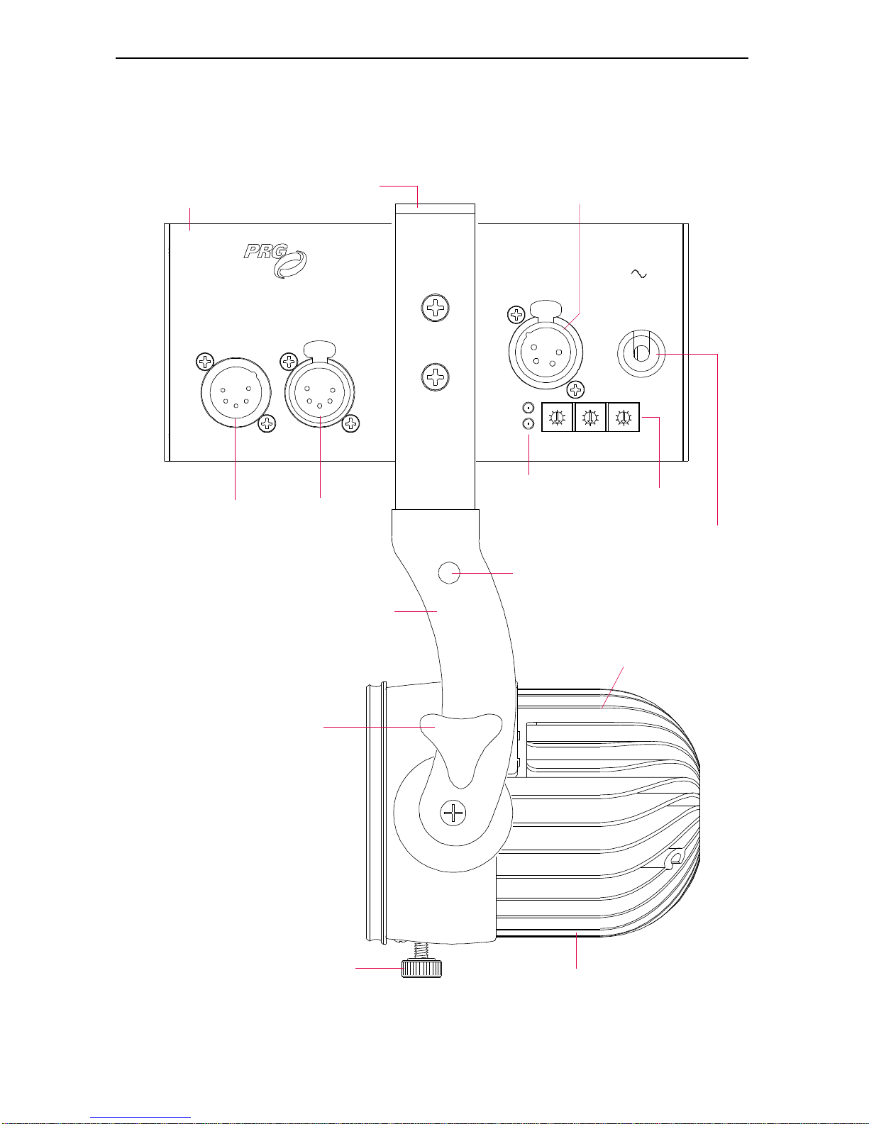
Major Components and Controls
The following illustration shows the components and controls of a Single Head Bullet
Luminaire. (These components are also typical of a Triple Head Bullet Luminaire.)
Figure 1: Bullet External Components and Controls
2
Page 3
3. INSTALLATION
Note: Example installation.
Individual configurations may vary
Note: Clamp and
Pipe not included.
Clamp
Pipe Safety Cable
Single Head
Head
AC Power Cord
Head Cable
Yoke
Mounting Bracket
Powe r Supply
Unified Mounting
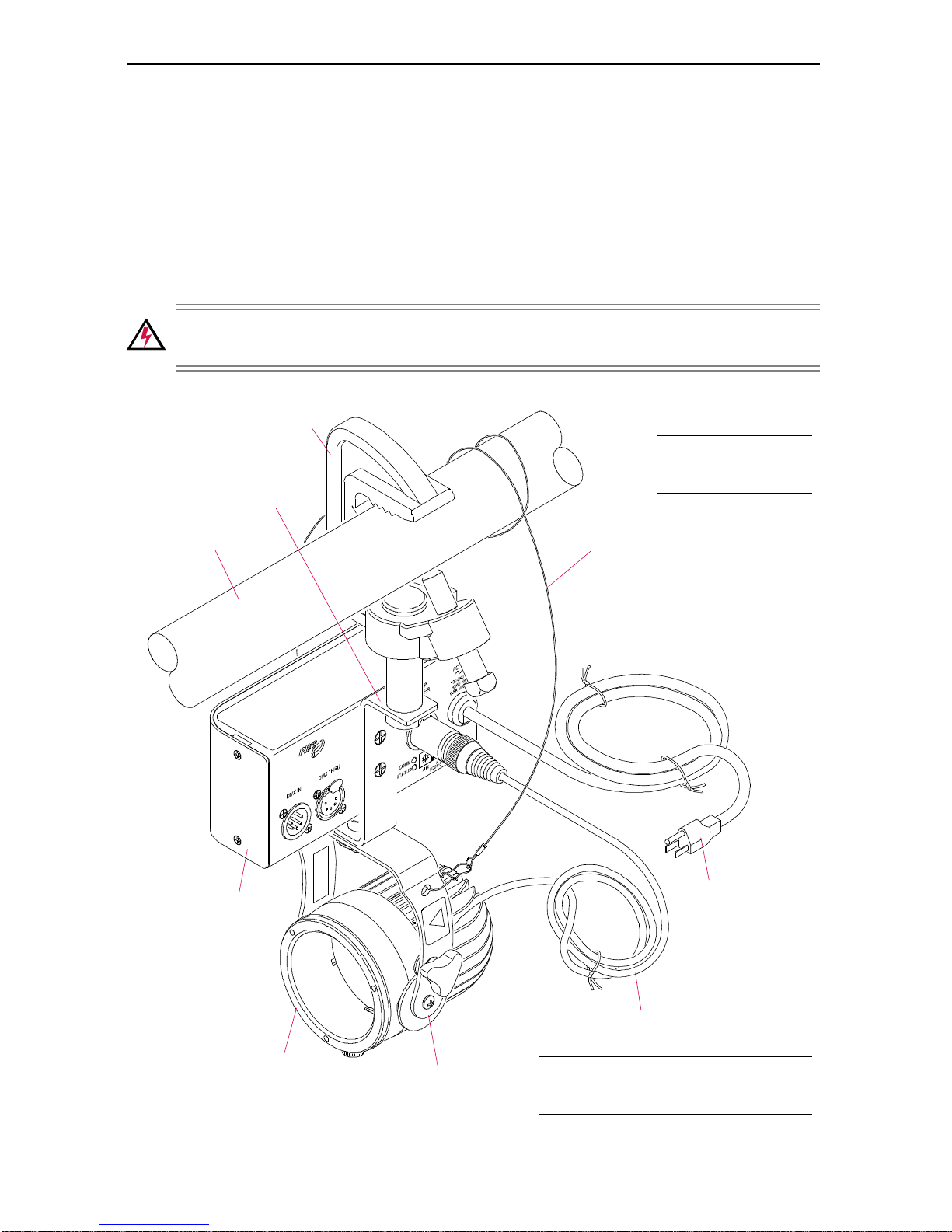
1) Attach pipe clamp or surface mounting device to large hole in Mounting Bracket.
(The hole is 1/2 inch in diameter and will accommodate a maximum bolt size of 1/
2 inch.)
2) Mount Luminaire and Power Supply to pipe or surface using clamp or mounting
device (attached in previous step). Adjust Yoke and Head positions as desired.
CAUTION: Be sure cooling fins are not blocked!
3) Attach Safety Cable as shown in Figure 2.
WARNING: A Safety Cable MUST be used for all hanging installations and may
be required by local codes.
Figure 2: Unified Mounting Example
3
Page 4
Split Mounting
Note: Clamps and Pipe not included.
Note: Example installation.
Individual configurations may vary
Pipe
AC Power Cord
Moun t in g Br ac k et
Clamp
Screw (2)
Single Head
Power Supply
Head
Head Cable
Yoke
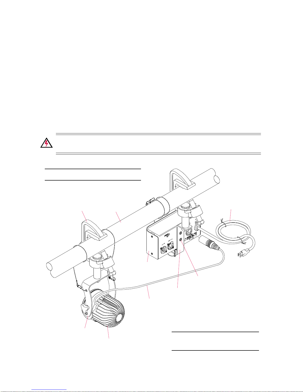
1) Detach Head from Mounting Bracket by removing bolt. Unwrap or otherwise free
Head Cable.
2) Attach pipe clamp or surface mounting device to large hole in Luminaire Yoke.
(The hole is 0.4 inch in diameter and will accommodate a maximum bolt size of 3/
8 inch.)
3) Mount Luminaire to pipe or surface using clamp or mounting device (attached in
previous step). Adjust Yoke and Head positions as desired.
CAUTION: Be sure
cooling fins are not blocked!
4) Attach pipe clamp or surface mounting device to large hole in Mounting Bracket.
(The hole is 1/2 inch in diameter and will accommodate a maximum bolt size of 1/
2 inch.)
5) Mount Power Supply to pipe or surface using clamp or mounting device (attached
in previous step).
6) Attach Safety Cable to both components as shown in Figure 3.
WARNING: A Safety Cable MUST be used for all hanging installations and may
be required by local codes.
Figure 3: Split Mounting Example
4
Page 5
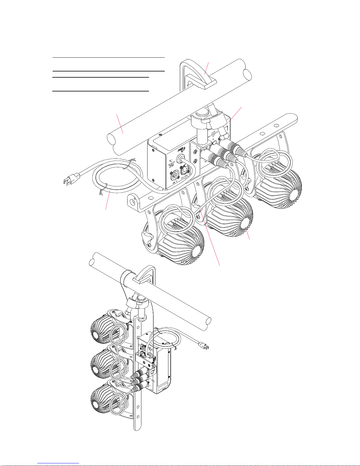
Triple Head Mounting
Note: Clamp and Pipe not included.
Clamp
Pipe
Triple Head
Head (3)
AC Power Cord
Head Cable (3)
Power Supply
Note: Safety Cable not shown.
VERTICAL HANG
CONFIGURATION
The mounting procedures for the Triple Head Bullet Luminaire are similar to the Single
Head mounting procedures detailed previously. The following illustration shows
example Triple Head unified configurations:
Figure 4: Triple Head Mounting Examples
5
Page 6
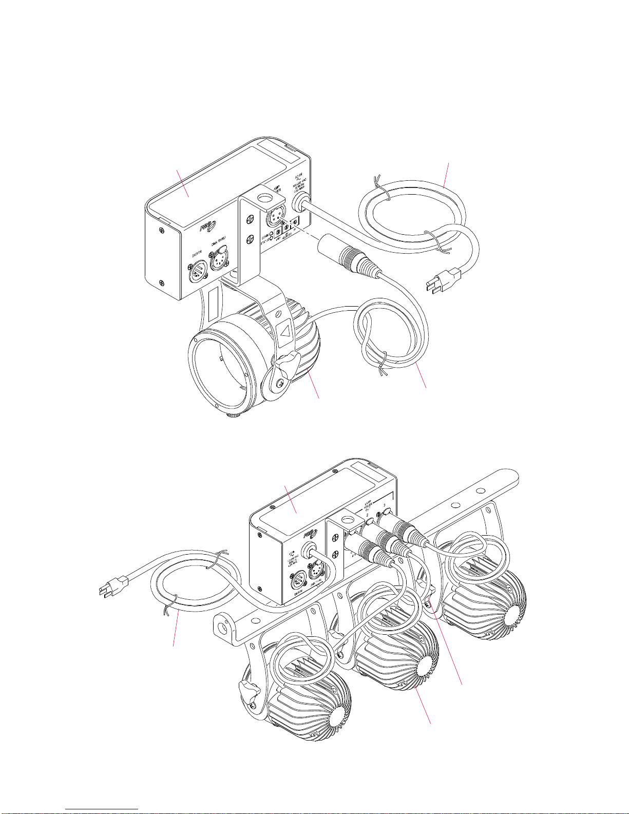
Connecting Head Cables (Lamp Power)
Head Cable
Single Head
Luminaire
AC Power Cord
Powe r Supply
Head Cable (3)
Luminaire (3)
AC Power Cord
Triple Head
Power Supply
Once the luminaire has been mounted, the Head Cable should be connected to the
Lamp Power Out connector on the Power Supply.
+ In a unified configuration, the Head Cable should be plugged straight into the
Power Supply.
+ In a split configuration, a 4-Pin XLR Extension Cable may be required.
Figure 5: Connecting Head Cable to Power Supply - Single Head
Figure 6: Connecting Head Cables to Power Supply - Triple Head
6
Page 7

4. POWER UP AND OPERATION
Power Up
Apply power to the Bullet Luminaire by plugging the Power Supply’s power cord into
an AC source. (The unit has no power on/off switch.)
LED Indicators
The Comm and Status LED indicators will be activated upon power up, whenever
rotary dials are changed, when DMX signal is lost (after a 15 second delay to avoid
short losses), when DMX signal is acquired, or upon over-temperature condition.
After activation, the LED indicators will remain active for 15 minutes unless otherwise
described below. (The timer will be reset by repeated activation events.)
Comm (Green) LED Status (Orange) LED Meaning
slow blink on/off n/a no incoming DMX
solid on n/a valid incoming DMX
n/a
blink code off / blink code firmware version *
* Firmware version blink codes will only be shown when rotary dials are set to a value
of 530 (see Standard Operating Modes below). The green Comm LED indicates the
major version and the orange Status LED indicates the minor version (off for zero).
rapid blink
(3-4 times per second)
over-temperature condition
Standard Operating Modes
The luminaire operating mode is set using the three rotary dials located on the Power
Supply. The three dials represent the 100’s digit, 10’s digit, and 1’s digit as marked. For
example, to set the address to 512, set the x100 dial to [5], the x10 dial to [1], and the
x1 dial to [2]. (Note that on a Triple Head Power Supply, DMX channels are sequential
for the 2nd and 3rd head attached.)
When the rotary dials are adjusted to a specific setting, the mode and behavior of the
luminaire will change immediately. Settings are as follows:
Setting Function
000 Full on (100%)
001-512 DMX channel address
530
550 Allow DMX address to be set via RDM *
600-700 Manual intensity, 0-100%
800-899 Manual strobe rate, slow to fast
900-999 Manual fade rate (pulse), slow to fast
other Full off (0%)
* All RDM functionality except setting the DMX address is available regardless of
thumbwheel value. Setting the thumbwheel to 550 also allows the DMX address of
the fixture to be set remotely via RDM commands.
Read out firmware version on LED indicators
(refer to LED Indicators section above)
7
Page 8
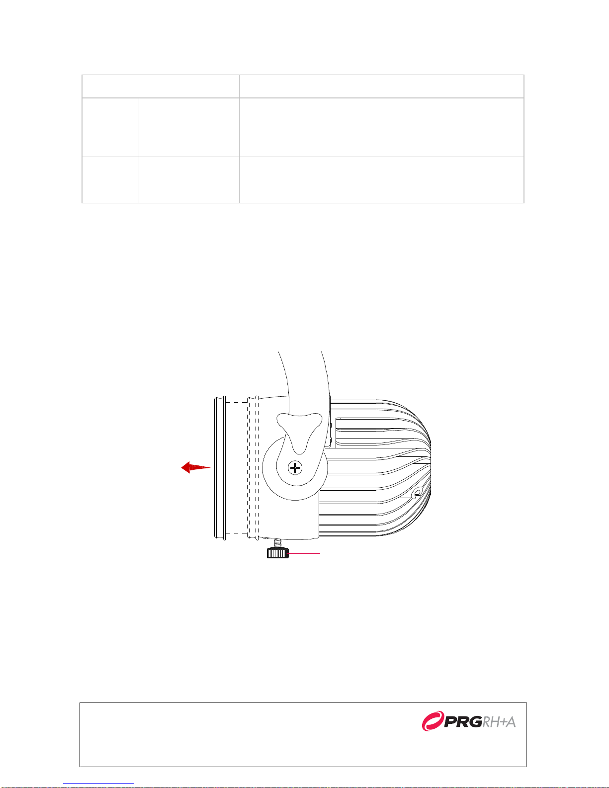
Exception Modes
Focus Lock
In case of a DMX signal loss or over-temperature condition, the luminaire will respond
as follows:
Condition Response
Luminaire will hold last "look" and resume DMX commands when valid DMX data is received again. (Also see
Blink function of the LED Indicators.)
NOTE: Look will not hold through power loss.
Output power is disabled until power is cycled or temperature falls below threshold. (Also see Rapid Blink function
of the LED Indicators.)
DMX
Fails
Over
Te mp
Valid DMX signal
is lost while in
DMX mode
Unit exceeds
temperature limit
RDM
The Bullet Luminaire supports basic RDM functionality per ANSI E1.20 (RDM-Remote
Device Management over USITT DMX512 Networks) specification.
Focusing the Beam
To focus the luminaire, loosen the Focus Lock knob and rotate the front of the barrel to
adjust the position of the lens. The more the barrel is extended, the more narrow the
beam.
Bullet Series 2.0 LED Luminaire Quick Start Guide
Version as of: September 14, 2015
PRG document number: 02.9832.0002 539 Temple Hill Road
©2015 Production Resource Group, LLC.
Figure 7: Focus Lock Knob
New Windsor, NY 12553-5533
 Loading...