

Page 1
USER MANUAL
02.9800.0001
Page 2

Mbox EXtreme™, AutoPar™, PRG Series 400™, Virtuoso®, Virtuoso® DX, Virtuoso® DX2, and Visionary™ 3D
are trademarks of Production Resource Group, LLC, registered in the U.S. and other countries.
Apple®, Macintosh®, Mac®, QuickTime® and FireWire® are registered trademarks of Apple Computer, Inc.
All other brand or product names which may be mentioned in this manual are trademarks or registered trademarks of their respective companies.
This manual is for informational use only and is subject to change without notice. Please check www.prg.com for latest version.
PRG assumes no responsibility or liability for any claims resulting from errors or inaccuracies that may appear in this manual.
Mbox Extreme™ Media Server User Manual
Version as of: September 27, 2006 | PRG part number: 02.9800.0001
Production Resource Group
Dallas Office
8617 Ambassador Row, Suite 120
Dallas, Texas 75247
www.prg.com
©2006 Production Resource Group, LLC. All Rights Reserved.
Mbox Extreme™ Media Server User Manual
Page 3

Safety Notice
It is extremely important to read ALL safety information and instructions provided in this manual and any
accompanying documentation before installing and operating the products described herein. Heed all cautions
and warnings during installation and use of this product. Safety symbols used throughout this manual are as
follows:
GENERAL INFORMATION PERTAINING TO PROTECTION AGAINST ELECTRICAL SHOCK, FIRE,
AND INJURY TO PERSONS CAN BE FOUND BELOW.
WARNING: INSTRUCTIONS FOR CONTINUED PROTECTION AGAINST ELECTRICAL SHOCK
1. PRG equipment is designed for dry locations only. Exposure to rain or moisture may damage equipment.
2. Disconnect power before servicing any PRG equipment.
3. Servicing to be performed by qualified personnel only.
FOREWORD
CAUTION advising of potential damage to product.
WARNING advising of potential injury or death to persons.
02.9800.0001 i
Page 4

MBOX EXTREME™ MEDIA SERVER USER MANUAL
Notes
ii 02.9800.0001
Page 5

Table of Contents
Introduction
About This Manual ...................................................................................................... 1
Additional Documentation........................................................................................... 1
Customer Service ......................................................................................................... 2
Chapter 1. Overview
Description
Features ........................................................................................................................ 4
Components
Mbox Extreme Case Assembly.................................................................................... 6
Theory of Operation
Data Flow Diagrams .................................................................................................... 8
DMX512 Input Configuration:
Single Media Server with DMX512 Devices........................................................ 8
Art-Net Input Configuration:
Network Switch and Multiple Media Servers ....................................................... 9
Chapter 2. Installation
Setup
Unpack and Hookup Procedure ................................................................................. 12
System Connection Procedure ................................................................................... 14
Power Up
Power Up Procedure .................................................................................................. 16
Power Down Procedure ............................................................................................. 16
Creating Network Connection ................................................................................... 17
Console Patch
Patching Fixtures........................................................................................................ 20
Quick Start
Generating Output...................................................................................................... 21
02.9800.0001 iii
Page 6

MBOX EXTREME™ MEDIA SERVER USER MANUAL
Chapter 3. Operation
Mbox Extreme Environment
Concept Overview...................................................................................................... 24
Layers......................................................................................................................... 26
Layer Components............................................................................................... 26
Layer Hierarchy................................................................................................... 26
Backgrounds............................................................................................................... 27
Textures ............................................................................................................... 28
Effects.................................................................................................................. 28
Transitions ........................................................................................................... 28
Play Modes .......................................................................................................... 29
Live Video Input.................................................................................................. 29
3D Objects.................................................................................................................. 30
3D Lighting................................................................................................................ 31
Camera ....................................................................................................................... 32
Control Channels................................................................................................. 32
Shutter ........................................................................................................................ 33
Keystone..................................................................................................................... 33
Application Window
Overview.................................................................................................................... 34
Starting the Mbox Extreme Application .................................................................... 35
Setup Window............................................................................................................ 36
Changing the Application Window Size.................................................................... 37
Closing the Application ............................................................................................. 37
Chapter 4. Media Content
Content Type
Images and Video Clips ............................................................................................. 40
Recommended Codecs............................................................................................... 40
3D Models (Objects).................................................................................................. 40
Content Management
Overview.................................................................................................................... 41
Folder and File Numbering ........................................................................................ 41
Preloaded Content ...................................................................................................... 42
Adding Video and Image Files................................................................................... 43
Adding 3D Objects..................................................................................................... 43
Chapter 5. Troubleshooting and Maintenance
Routine Maintenance
Cleaning or Replacing the Air Filter.......................................................................... 46
Removing Computer from Case ................................................................................ 47
iv 02.9800.0001
Page 7

Appendix A. DMX Channel Mapping
DMX Operation
Channel Mapping....................................................................................................... 50
Combined DMX Channel Map ........................................................................... 50
Control Channels................................................................................................. 59
SDI Shutter Control............................................................................................. 59
Shutter Shapes ..................................................................................................... 59
Play Modes .......................................................................................................... 60
Aspect Control..................................................................................................... 60
Blending Control ................................................................................................. 60
Tiling Modes ....................................................................................................... 61
Texture Effects .................................................................................................... 62
Transitions ........................................................................................................... 63
Built-In Shapes .................................................................................................... 65
Appendix B. Reference Charts
Virtuoso® Console
Virtuoso Profiles and Channel Map ........................................................................... 68
Miscellaneous
Effects and Transitions............................................................................................... 73
Texture Effects .................................................................................................... 73
Transitions ........................................................................................................... 75
02.9800.0001 v
Page 8

MBOX EXTREME™ MEDIA SERVER USER MANUAL
Notes
vi 02.9800.0001
Page 9
Introduction
About This Manual
This manual provides necessary information regarding product safety, installation, and operation for
the following PRG equipment:
• Mbox Extreme™ Media Server
Familiarizing yourself with this information will help you get the most out of your PRG product.
WARNING: It is important to read ALL accompanying safety and installation instructions to avoid
damage to the product and potential injury to yourself or others.
Additional Documentation
INTRODUCTION
For more information regarding DMX512 systems, refer to the DMX512/1990 & AMX 192 Standards
publication available from United States Institute for Theatre Technology, Inc. (USITT).
USITT
6443 Ridings Road
Syracuse, NY 13206-1111 USA
1-800-93USITT
www.usitt.org
02.9800.0001 1
Page 10

MBOX EXTREME™ MEDIA SERVER USER MANUAL
Customer Service
Our comprehensive technical services department ensures you get the full benefit of being a PRG
customer. Whether your needs are simple or complex, our full-time staff of experienced professionals
are on-hand to provide support. For assistance, contact your nearest PRG office:
PRG Dallas (International Service)
8617 Ambassador Row, Suite 120
Dallas, Texas 75247
Ph: 1.214.630.1963
Fx: 1.214.630.5867
Service Fx: 214.638.2125
Service Email: [email protected]
PRG Los Angeles
9111 Sunland Blvd.
Sun Valley, California 91352
Ph: 1.818.252.2600
Fx: 1.818.252.2620
PRG New York
7777 West Side Avenue
North Bergen, New Jersey 07047
Ph: 1.201.758.4000
Fx: 1.201.758.4312
PRG Europe
20-22 Fairway Drive
Greenford, Middlesex, UB6 8PW
Ph: +44.208.575.6666
Fx: +44.208.575.0424
PRG Nashville
5215 Linbar Drive, Suite 201
Nashville, Tennessee 37211
Ph: 1.615.834.3190
Fx: 1.615.834.3192
PRG Las Vegas
6050 S. Valley Vw Blvd.
Las Vegas, Nevada 89118
Ph: 1.702.942.4774
Fx: 1.702.942.4775
PRG Orlando
7576 Kingspointe Parkway, Suite 160
Orlando, Florida 32819
Ph: 1.407.855.8060
Fx: 1.407.855.8059
PRG Asia
Asagami Fukagawa Logistics Center B-4F
2-2-1 Shiohama, Koto-ku, Tokyo, Japan 135-0043
Ph: 81.3.5439.4091
Fx: 81.3.5439.4092
PRG Canada
2480 Tedlo Street
Mississauga, Ontario L5A 3V3 Canada
Ph: 905.270.9050
Fx: 905.270.2590
For additional resources and documentation, please visit our website at: www.prg.com
2 02.9800.0001
Page 11

1.
Overview
This chapter provides an overview of product features, components, and operations.
• Description
• Components
• Theory of Operation
02.9800.0001 3
Page 12
MBOX EXTREME™ MEDIA SERVER USER MANUAL
Description
Features
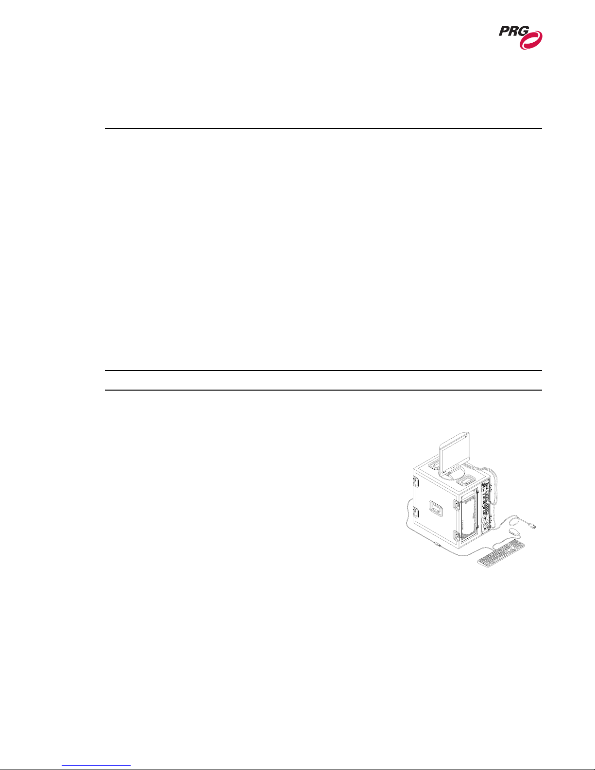
The Mbox Extreme™ Media Server is a case-mount unit which allows advanced integration of video
and automated lighting. Powerful real time rendering, built-in effects, and interactive 3D objects
provide tools for combining pre-recorded video and still images to create visual imagery, which can be
displayed by any projector, LED wall, plasma screen or low-res LED lighting fixture.
The Mbox Extreme server can be programmed and operated directly from DMX512-based moving
light consoles, allowing ease of coordination between video/image effects and lighting cues. Intricate
Mbox Extreme sequences can be generated instantly on site without the need for offline video
processing, rendering or editing. The Mbox Extreme stock library includes a wide variety of video
clips, still images and 3D objects. Custom media files may also be added.
The Mbox Extreme software runs on a rack-mounted Apple® Macintosh® G5 computer controlled by
DMX512 or Art-Net. All video, still images and 3D objects are stored on directly on the Mbox
Extreme hard drive, allowing instant access to any file. Mbox Extreme is available in either a single or
dual-server rack and each server is equipped with one video output that can be used to drive a
projector, LED wall or plasma screen. The included I/O module provides analog (RGBHV), DVI, SDI
and HD-SDI outputs for video.
Note: The Mac® G5 provided requires the Tiger™ (10.4) operating system.
Feature List
• Real time rendering.
• Movable camera viewpoint.
• Keystone correction.
• Ambient and directional light sources.
• Five interactive, scalable layers that can be configured as
backgrounds or 3D geometric objects.
• Digital gobos that can be used as backgrounds, masks or for
advanced layer blending effects.
• Image tiling and edge-blending.
• Pixel mapping.
• Layer break-out view.
• Mapping of textures (videos or still images) to 3D objects and digital gobos.
• Real time crossfades and transitions between videos and images on the same layer.
• Effects including blur, pixelate, LED Wall, twirl, color, exposure and alpha adjustment can be
applied individually or in combination.
• Accepts live video input – SDI, Composite and FireWire® (DV).
• Advanced video playback with direction, speed and in-point/out-point control.
• User-configurable aspect ratio and output resolution control.
• Control by DMX512 or Art-Net.
4 02.9800.0001
Page 13

OVERVIEW : DESCRIPTION
• Stores up to 65,535 videos and still images.
• Stores up to 65,535 3D objects.
• Starter media library and objects.
• Hardware I/O module with built in DMX - Art-Net converter and Ethernet switch. Analog
(RGBHV), DVI, SDI and HD-SDI video outputs.
• Live video inputs can be shared between multiple servers using Ethernet.
Controllable Elements
Light (4 directional, 1 ambient)
• Intensity
• Color
Camera (1)
• Orbit X and Y
•Dolly
• Camera Roll (Spin)
• Field of View
• Theatrical Framing Shutters (four modes)
• Shutter X and Y
• Shutter Scale
• Shutter Edge
• Keystone X and Y
• Keystone Scale
• Keystone Skew
• Edge Blending
• Tiling
• Master Effect (2)
• Master Color
1
Object: Background/Shape (5)
• Transparency
• Shape
•Texture
• Texture Effect (2 per object)
• Color
• Playmode
• Playspeed
• Transitions (Type and Timing)
• X, Y, Z Position
• X, Y, Z Rotation (Spin)
• X, Y, Z Scale
02.9800.0001 5
Page 14
MBOX EXTREME™ MEDIA SERVER USER MANUAL
Components
Mbox Extreme Case Assembly
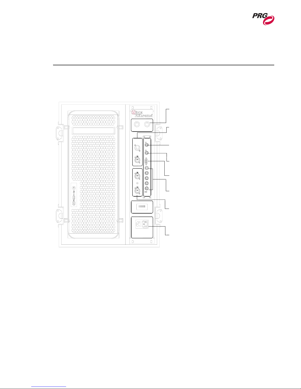
The following illustrations show the case components.
DIMMER CONTROL
MAIN
OUTPUT
DBO
DATA I/O
DMX
MONITOR
OUTPUT
Dimmer Control - used to shut off either the main
output or mimic main output on the local monitor.
FULL
SDI OUTPUTGENLOCK MONITOR R
Data I/O- used to input either DMX512 or Art-Net data
from the control console.
Genlock Output - used to synchronize additional
Mbox Extreme Media Servers (not yet implemented).
ETHERNET
ETHERNET HUB
G B H V
SDI Output - used to output video data in SDI
format.
Monitor Output - used to output data to the local
HUB POWER
ACTIVE
POWER
monitor.
BNC Output- BNC (RGBHV) outputs
data to video device.
PRG
7257730
PRG
Ethernet Hub- contains an Ethernet switch
with RJ-45 connections for linking Mbox
Extreme Server with the local network.
100-240 VAC
50-60 HZ
8 AMPS
Power Input - used to receive power from
the wall outlet and provides an outlet to
power the local monitor.
FRONT VIEW
Figure 1-1: Case Components / Front View
6 02.9800.0001
Page 15
OVERVIEW : COMPONENTS
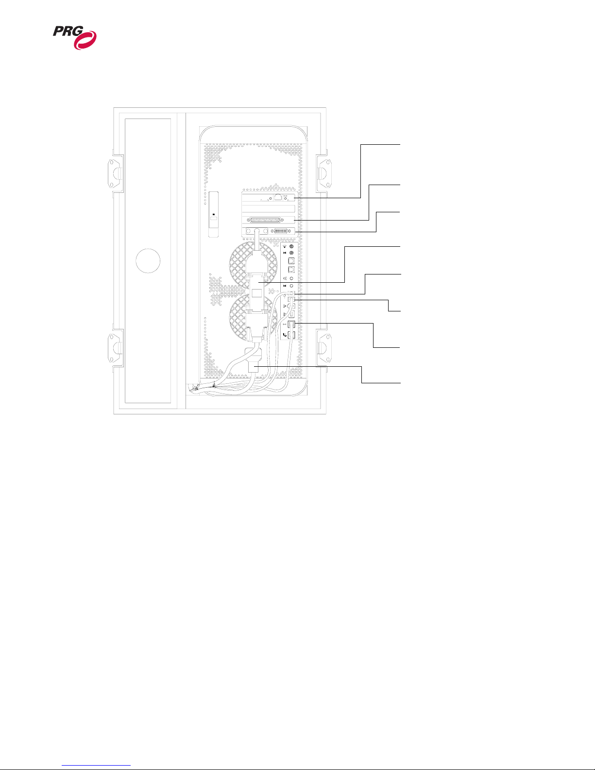
Ethernet Card - provides additional
network card for optional connection to
local computer network.
Video Input - optional card for
connecting live video source.
Video Output - DVI / VGA connection
supplies video to front I/O panel.
Dongle - used by the application to set
out
optical
audio
in
up the correct monitor configuration.
Keyboard / Mouse Output - USB
connection for keyboard and mouse
devices.
Dimmer Control - USB connection
provides local Dimmer Control to front
I/O panel.
1
Built-In Ethernet Connection provides network connection to front I/O
panel.
Power Supply - provides AC power
to the Apple® Macintosh® G5
computer.
Figure 1-2: Case Components / Rear View
02.9800.0001 7
Page 16
MBOX EXTREME™ MEDIA SERVER USER MANUAL
Theory of Operation
Data Flow Diagrams
DMX512 Input Configuration:
Single Media Server with DMX512 Devices
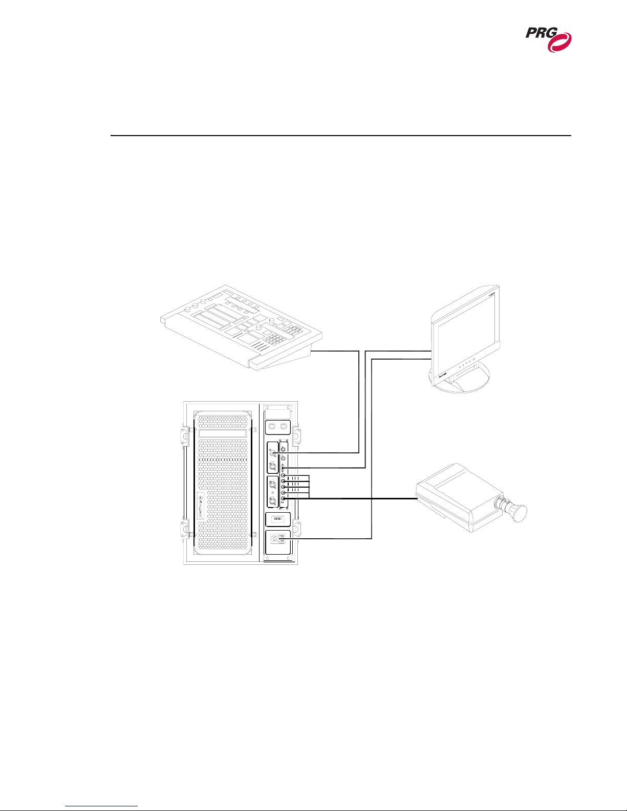
In the following configuration, DMX512 control signal is distributed from one DMX512 console to
multiple DMX512 devices and one Mbox Extreme Media Server. Data is then distributed from the
Mbox Extreme Media Server to the other components as shown below.
DMX CONSOLE
LOCAL DISPLAY
DMX IN
VIDEO OUT
VIDEO OUT
POWER OUT
MBOX EXTREME
RGBHV
PROJECTOR
Figure 1-3: Single Media Server with DMX512 Devices
8 02.9800.0001
Page 17
OVERVIEW : THEORY OF OPERATION
Art-Net Input Configuration:
Network Switch and Multiple Media Servers
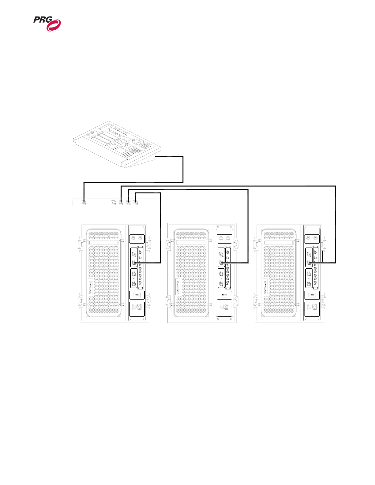
In the following configuration, Art-Net control signal is distributed from one control console to one
network switch. The network switch then distributes the control signal to all Mbox Extreme Media
Servers.
Art-Net
DMX CONSOLE
1
NETWORK SWITCH
MBOX EXTREME
Figure 1-4: Network Switch and Multiple Media Servers
IN
MBOX EXTREME MBOX EXTREME
IN IN
02.9800.0001 9
Page 18

MBOX EXTREME™ MEDIA SERVER USER MANUAL
Notes
10 02.9800.0001
Page 19

2.
Installation
This chapter provides instructions for unpacking the Mbox Extreme case, connecting to the system
and powering up.
• Setup
• Power Up
• Creating Network Connection
• Console Patch
02.9800.0001 11
Page 20
MBOX EXTREME™ MEDIA SERVER USER MANUAL
Setup
Unpack and Hookup Procedure
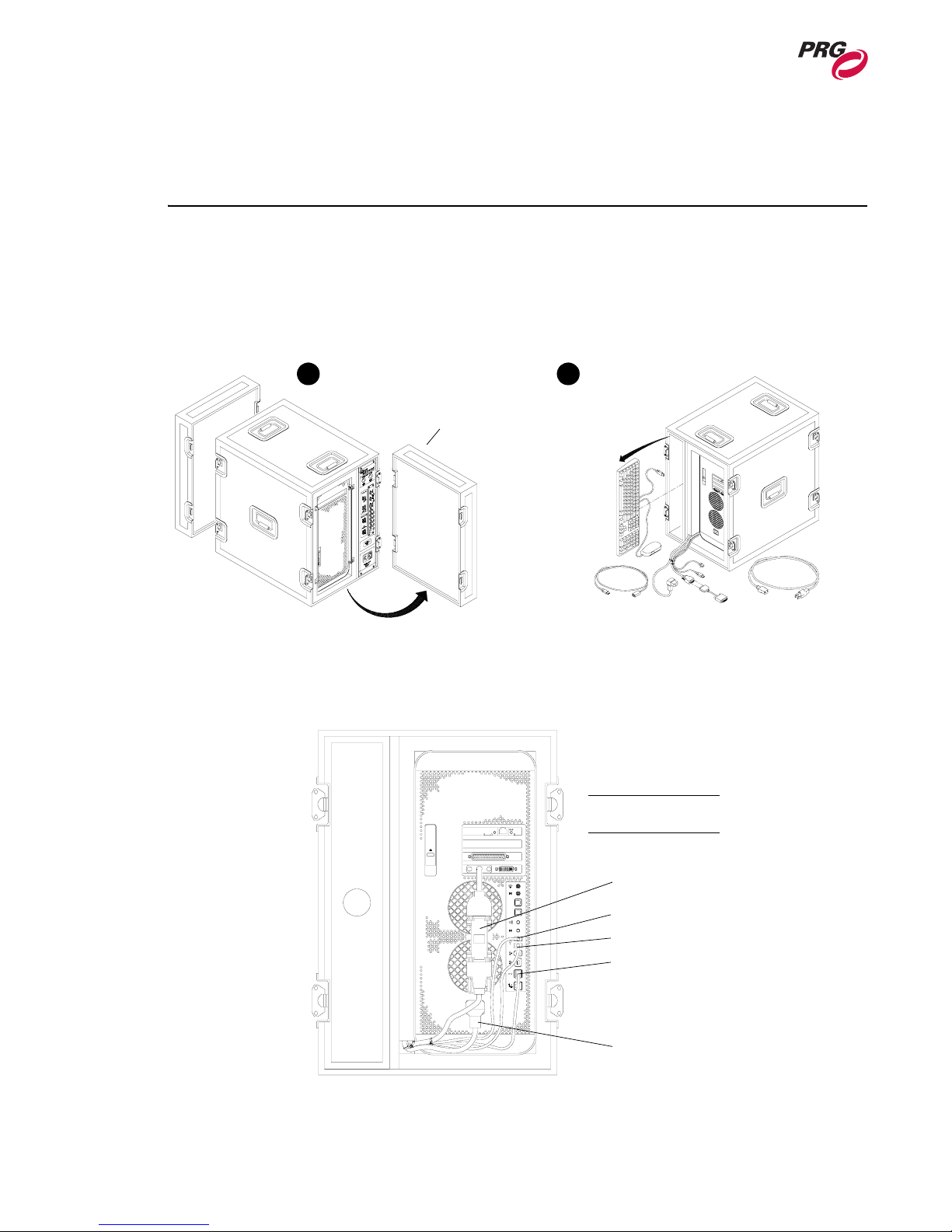
To set up case components:
Step 1. Remove front and back covers from case (Figure 2-1).
Step 2. Remove keyboard and mouse from back of case.
1 2
Remove covers
Remove components
Figure 2-1: Removing Covers and Components
Step 3. At rear of case, verify that Monitor/Dongle, Keyboard/Mouse, USB, Ethernet and Power
cables are connected to computer (Figure 2-2).
NOTE:
Also refer to Figure 1-2.
Monitor/Dongle
out
optical
audio
in
Keyboard/Mouse
USB
Ethernet
Power
12 02.9800.0001
Figure 2-2: Rear Cable Connections
Page 21
INSTALLATION : SETUP
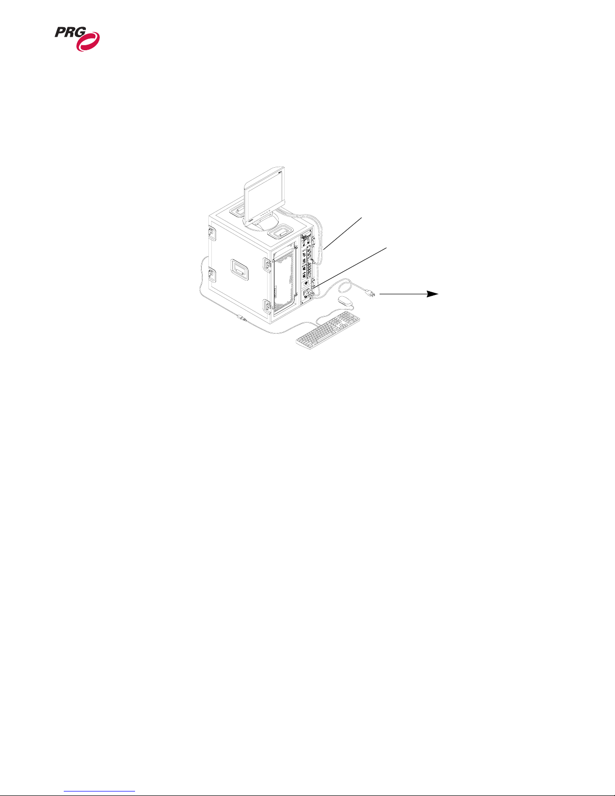
Step 4. At front of case, connect local monitor data cable to VGA connector (Figure 2-3).
Step 5. Connect local monitor power cable to power outlet on front of case or to local AC power
service.
Step 6. Connect case power cable to front of case, then to local AC power service.
Connect monitor
data cable
Connect monitor
AC cable
To Local AC Power Service
2
Figure 2-3: Connecting Monitor Power and Data Cabling
02.9800.0001 13
Page 22
MBOX EXTREME™ MEDIA SERVER USER MANUAL
System Connection Procedure
Once the case is set up and in place, connect to your control and video output devices.
To connect to the system:
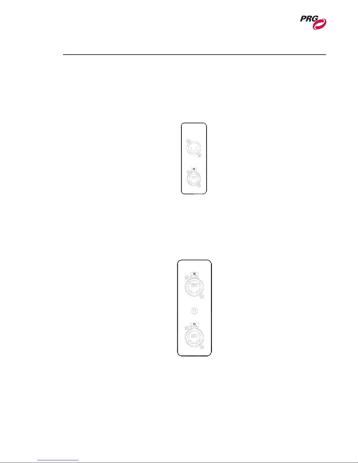
Step 1. For DMX512 controllers:
a. At Data I/O unit, connect console or DMX512 controller to DMX connector as required.
DATA I/O
DMX
ETHERNET
Figure 2-4: Connecting DMX512 Control Devices
Step 2. For Art-Net consoles:
a. At Data I/O unit, connect console to any Ethernet connector (Figure 2-4).
b. If desired, connect additional Ethernet devices (such as a media server, network switch
or dimmer rack) to additional Ethernet ports provided by the Ethernet Hub (Figure 2-5).
Figure 2-5: Connecting Additional Devices to Ethernet Hub
ETHERNET HUB
HUB POWER
14 02.9800.0001
Page 23
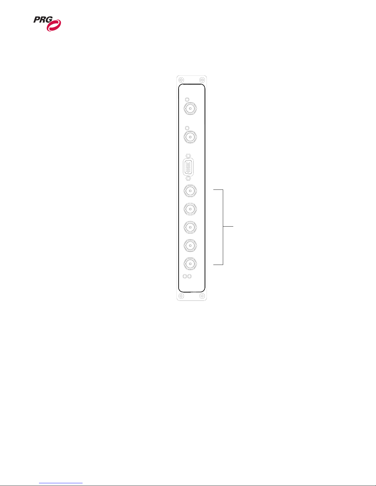
Step 3. At BNC connections, connect to output device.
GENLOCK
SDI OUTPUT
MONITOR
R
G B H V
INSTALLATION : SETUP
2
RGBHV Video
BNC Connectors
ACTIVE
POWER
Figure 2-6: Connecting Output Devices
02.9800.0001 15
Page 24
MBOX EXTREME™ MEDIA SERVER USER MANUAL
Power Up
Power Up Procedure
To power up the Mbox Extreme Media Server and launch the application:
Step 1. At front of case, press main power switch on Macintosh® G5 computer.
Step 2. At local monitor, press power switch.
Step 3. Wait for computer to initialize. The Mbox Extreme application will start automatically.
Note: If the application does not start automatically, locate the Mbox Extreme icon on the Apple Dock
and click once. For more information, see “Starting the Mbox Extreme Application” on page 35.
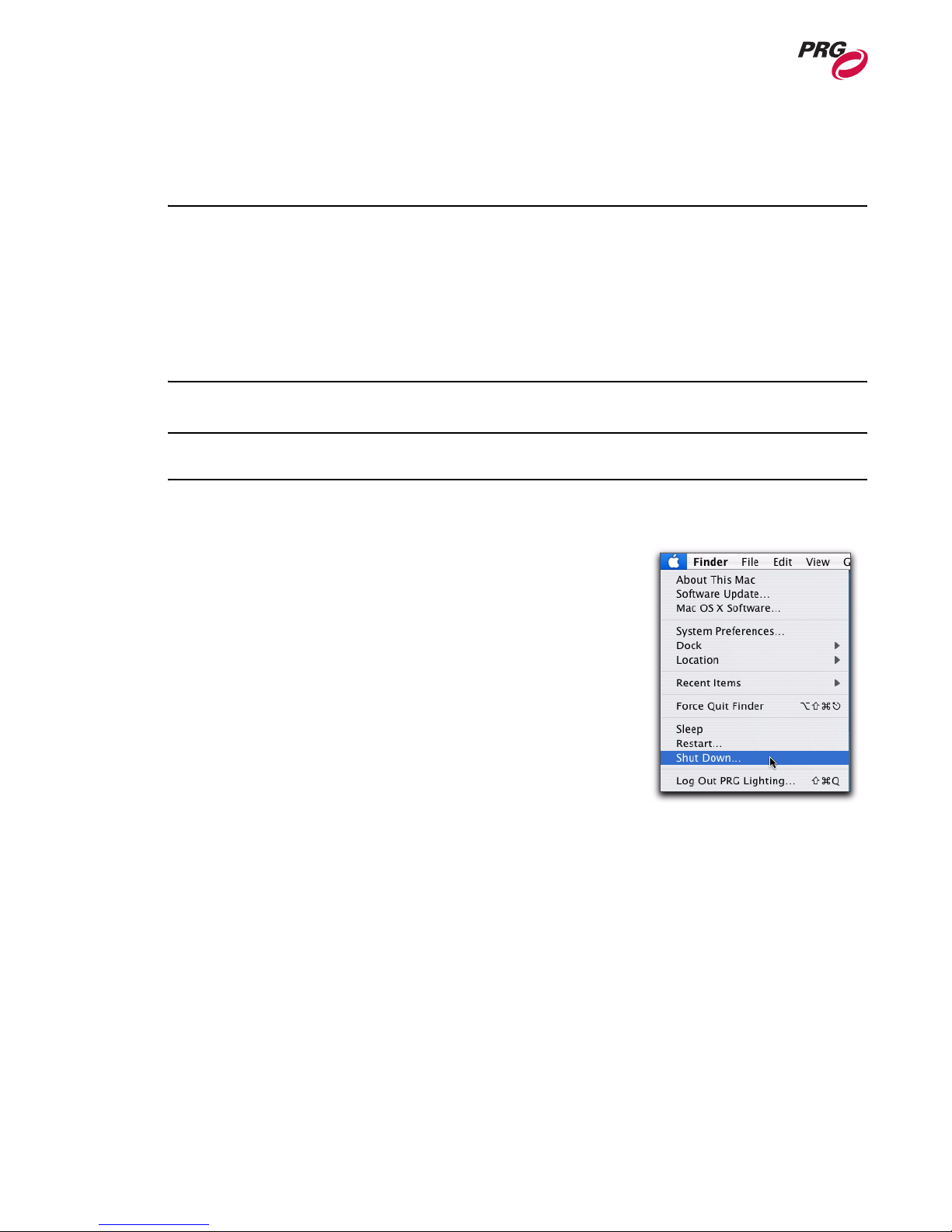
Power Down Procedure
To power down case:
Step 1. If in full-screen mode, press
screen size.
Step 2. Quit Mbox Extreme application by pressing
or selecting Quit Mbox Extreme from the Mbox
Extreme menu.
Step 3. At Apple menu, select Shut Down.
Step 4. At monitor, press power switch.
b / [F] to minimize
b / [Q]
16 02.9800.0001
Page 25
INSTALLATION : POWER UP
2
Creating Network Connection
The network connection for the built-in Mac G5 Ethernet card should arrive with the Art-Net
connection already configured. If the Art-Net connection is not pre-configured, use the following steps
to create the connection.
To create the built-in network connection:
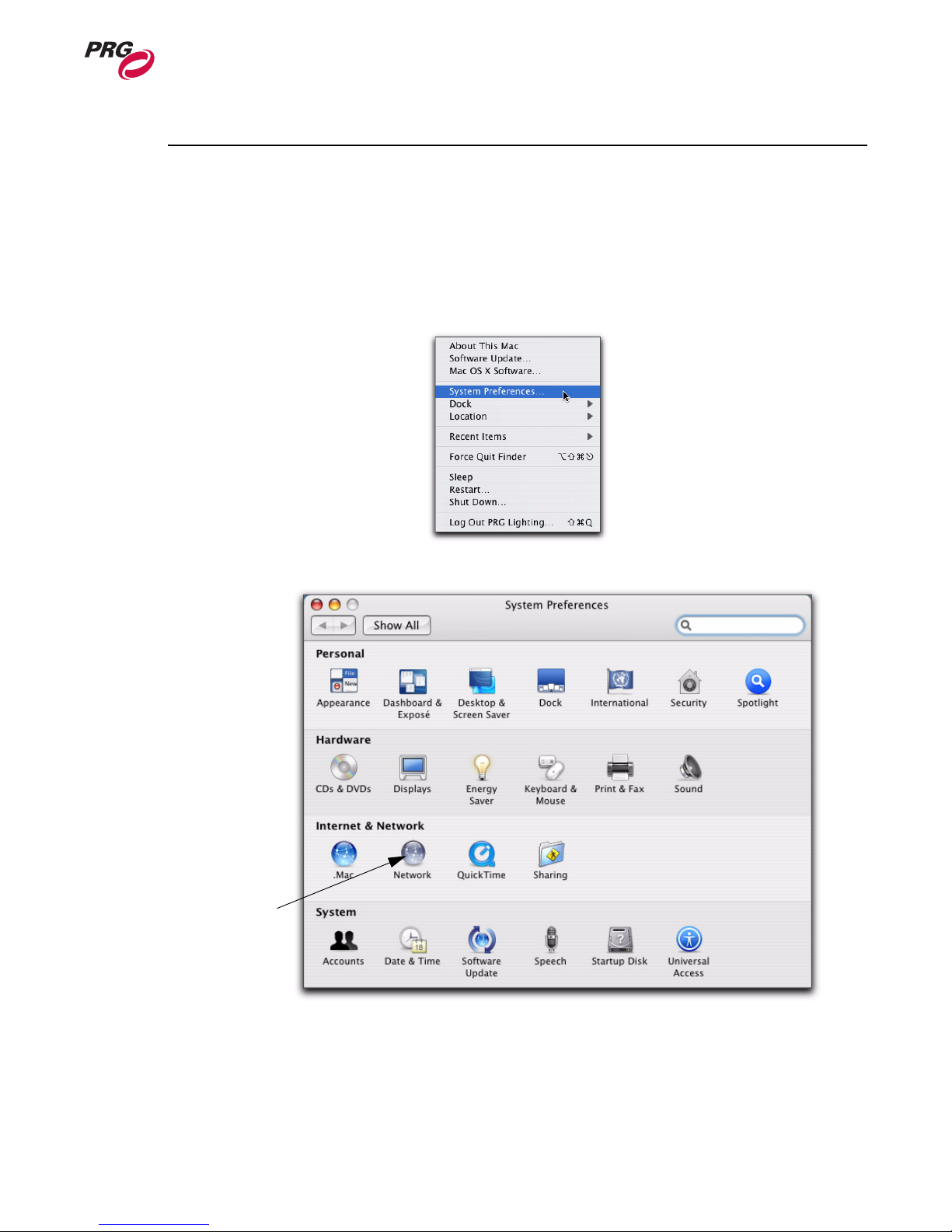
Step 1. At Apple menu, select System Preferences.
Step 2. In System Preferences window, select Network icon.
Network Icon
02.9800.0001 17
Page 26
MBOX EXTREME™ MEDIA SERVER USER MANUAL
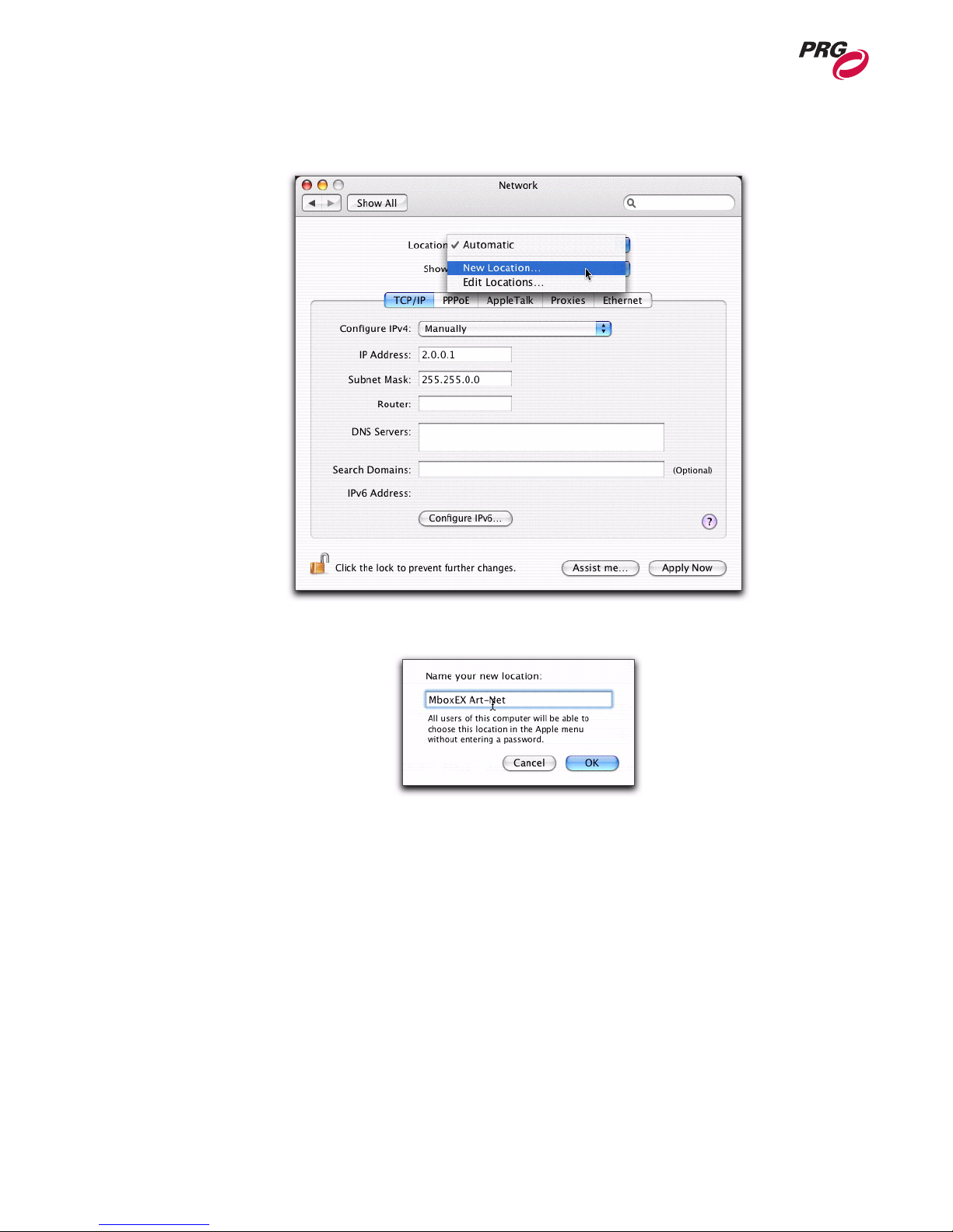
Step 3. In Network window, select Location drop-down and click New Location.
Step 4. The Name Location window appears. Enter location name and click OK..
18 02.9800.0001
Page 27
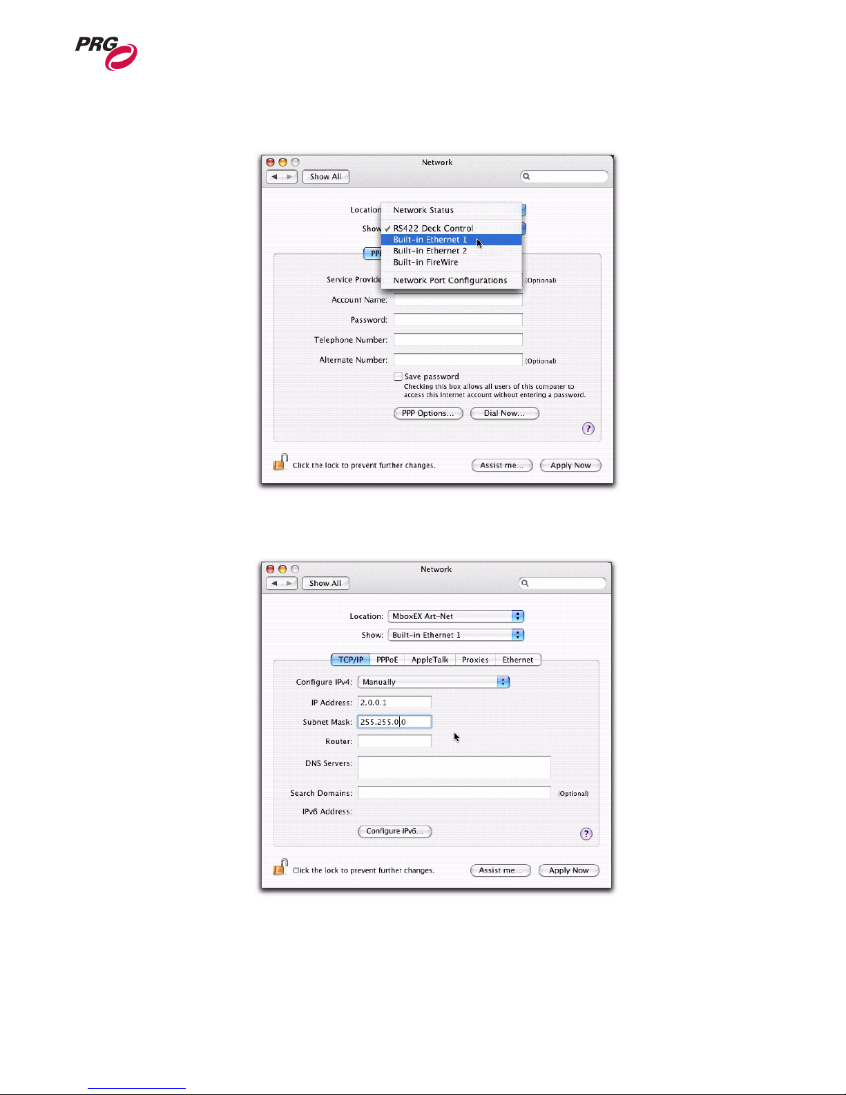
Step 5. Select Show drop-down and click Built-In Ethernet 1.
INSTALLATION : POWER UP
2
Step 6. Enter the IP Address. This address is required to begin with 2.0.0.x, with each device in your
network having a unique number for x between 1-254.
Step 7. Enter the Subnet Mask as 255.255.0.0.
Step 8. Click Apply Now.
02.9800.0001 19
Page 28

MBOX EXTREME™ MEDIA SERVER USER MANUAL
Console Patch
Patching Fixtures
The Mbox Extreme Media Server is designed to work with moving-light consoles. Each console
requires a fixture profile for the Mbox Extreme Media Server. It is strongly recommended that all
fixtures be patched in the order listed in the table below.
Table 2-1: Fixture Order
Fixture
Number
1 Ambient Light 4 1-4
2 Spotlight 1 4 5-8
3 Spotlight 2 4 9-12
4 Spotlight 3 4 13-16
5 Spotlight 4 4 17-20
6 Camera 26 21-46
7 Shutters 20 47-66
8 Keystone 22 67-88
9 Texture 1 30 89-118
10 Object 1 23 119-141
11 Texture 2 30 142-171
12 Object 2 23 172-194
13 Texture 3 30 195-224
14 Object 3 23 225-247
15 Texture 4 30 248-277
16 Object 4 23 278-300
17 Texture 5 30 301-330
18 Object 5 23 331-353
Description
Number of
Channels
DMX Channel
Note: In the event you require additional profiles, they can be found on the PRG website at:
www.prg.com. To request a profile not provided on the website, please contact the PRG Dallas office
at 214.630.1963.
20 02.9800.0001
Page 29

Quick Start
Generating Output
After connecting all components, patching all fixtures, and turning on the output device(s), you can
follow these procedures to get the Mbox Extreme Media Server up and running.
To generate Background output:
Step 1. Set Camera Intensity to value 255.
Note: The Camera Intensity channel controls the built-in dimmer on the I/O module. If this channel is
set to 0, no output will appear on the output device.
Step 2. Select Texture 1 and Object 1 channels. Set Transparency to full (255). White square will
appear on display.
Step 3. Deselect Object 1 channel, so that only Texture 1 channel is selected.
INSTALLATION : QUICK START
2
Step 4. Set Library parameter to value 253. (This selects the pre-loaded PRG stock content folder.)
Step 5. Set Texture parameter to value 007. You should see a PRG logo. (The file selected is named
007.MboxExtreme-Logo.jpg.)
Step 6. Adjust scale, color and other parameters as desired.
To generate 3D Object output:
Step 1. Set Camera Intensity to value 255.
Step 2. To provide surface lighting for the 3D Object, select at least one Ambient light or Spot light
channel and set value to 255.
Step 3. Select Texture 1 and Object 1 channels. Set Transparency to value 255. A white square will
appear on display.
Step 4. Deselect Texture 1 channel. Only Object 1 channel should now be selected.
Step 5. Set 3D Object Library parameter to value 0 to access built-in 3D models.
Step 6. Set Object Number parameter value to 001. White sphere will appear on display.
Step 7. Adjust rotation and scale parameters as desired.
02.9800.0001 21
Page 30

MBOX EXTREME™ MEDIA SERVER USER MANUAL
Notes
22 02.9800.0001
Page 31

3.
Operation
This chapter provides an overview of the Mbox Extreme Media Server Environment, along with
instructions for setup and operation of the Mbox Extreme application window.
• Mbox Extreme Environment
• Application Window
02.9800.0001 23
Page 32

MBOX EXTREME™ MEDIA SERVER USER MANUAL
Mbox Extreme Environment
Concept Overview
In order to get the most out the Mbox Extreme Media Server, it is important to understand the overall
concept of the Mbox Extreme Environment, which is essentially a building platform for "virtual
scenery." The final "look" of this virtual scenery can be comprised of backgrounds, 3D objects, camera
angles, and lighting, all of which are controllable elements within the Mbox Extreme Environment.
Likewise, each of these elements has a set of controllable parameters such as color, texture, size, and
movement. When all combined, you can achieve an infinite number of possibilities for your virtual
scenery.
At first, the interaction of these elements may seem complicated, but as we break down each
component individually, you will find that they are similar to automated lighting parameters which you
may already be familiar with. The only difference is that luminaire parameters coincide with physical
hardware - i.e. beam parameters control an iris - while the Mbox Extreme parameters coincide with
software elements. For example, just as you would control a luminaire’s beam color from a console
encoder or keypad, you can control the color of an Mbox Extreme 3D object. Once configured, the
entire Mbox Extreme Environment (i.e. virtual scenery) can be sent to any video compatible device
connected to the unit.
24 02.9800.0001
Page 33
OPERATION : MBOX EXTREME ENVIRONMENT
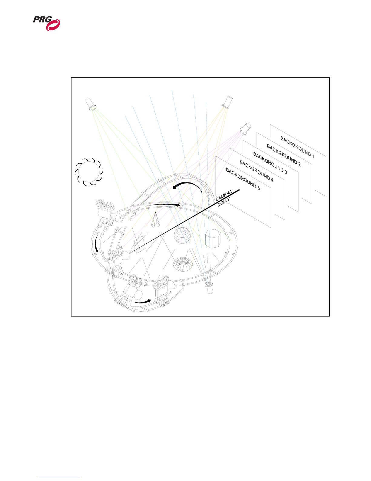
The following illustration is a virtual representation of each element within the Mbox Extreme
Environment. (More detailed descriptions of each element are provided on subsequent pages.)
3
3D OBJECT
DIRECTIONAL
SPOT LIGHT
3D
OBJECT
AMBIENT
LIGHT
ORBITY
3D OBJECT 2
3D OBJECT 1
3D OBJECT 3
DIRECTIONAL
SPOT LIGHT
3D OBJECT 5
3D OBJECT
DIRECTIONAL
ORBIT
3D OBJECT
SPOT LIGHT
X
CAMERA
3D OBJECT 4
DIRECTIONAL
SPOT LIGHT
Figure 3-1: Mbox Extreme 3D Environment Overview
02.9800.0001 25
Page 34
MBOX EXTREME™ MEDIA SERVER USER MANUAL
Layers
The Mbox Extreme 3D Environment provides up to five different layers that can be used as
Backgrounds or 3D Objects. You can use any combination of Backgrounds or 3D Objects up to five
total. For example, you can create two Backgrounds and three 3D Objects or one Background and four
3D Objects.
Layer Components
Due to the complexity of the 3D Object manipulation, all layers are comprised of two components: a
Texture (30 channels) and Object (23 channels). Even when not using 3D Objects, the Object channels
contain parameters used to control attributes of the Texture.
Note: Transparency must be set to 100% on both the Texture and Object channels to view a
Background or 3D Object. The Transparency levels on the Background and 3D Object components for
the same layer are additive. If both levels are set to 50%, the image transparency appears to be about
25%.
Note: If 3D Objects are not being used, the Transparency channel should be set to 100% in the fixture
library.
Layer Hierarchy
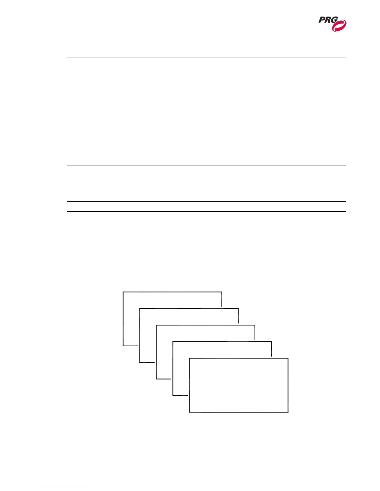
The Layer Hierarchy, the order in which layers appear, is determined by numerical order and layer
content. 3D Objects always appear in front of Background layers. Background layers appear in
numerical order, back to front.
LAYER 1
LAYER 2
LAYER 3
LAYER 4
LAYER 5
26 02.9800.0001
Figure 3-2: Background Order
Page 35
OPERATION : MBOX EXTREME ENVIRONMENT
Backgrounds
The Mbox Extreme 3D Environment provides up to five Background elements. Parameters such as
transparency level, color, texture, scale, and rotation can be configured for each, independently, to
create a backdrop for your virtual scenery.
All backgrounds have the following controllable elements:
• Transparency
•Textures
• Texture Effects
• Transitions
• Color
• Scale
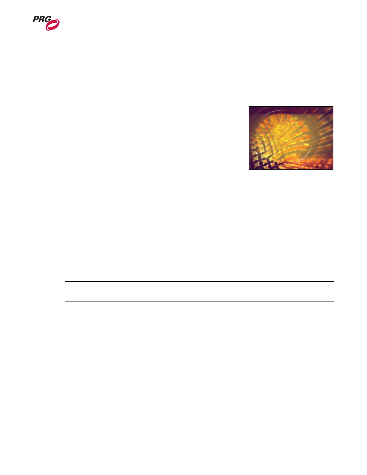
Sample Background
• X, Y Position
• Z rotation (Spin)
• Play mode and speed
3
•In / Out Frame
• Aspect
• Blending
• Texture Effect (2 per object)
• XFade type and timing
Creating a Background using DMX512 control:
Step 1. Set Camera Intensity to value 255.
Note: The Camera Intensity channel controls the built-in dimmer on the I/O module. If this channel is
set to 0, no output will appear on the output device.
Step 2. Select Texture 1 and Object 1 channels. Set Transparency to full (255). A white square will
appear on display.
Step 3. Deselect Object 1 channel, so that only Texture 1 channel is selected.
Step 4. Adjust desired parameters for Texture as desired.
For more information on background properties, see See “Mbox Extreme Combined DMX Channel
Map” on page 50.
02.9800.0001 27
Page 36
MBOX EXTREME™ MEDIA SERVER USER MANUAL
Textures
The Mbox Extreme Environment includes the ability to apply
textures to the Backgrounds and/or 3D Objects. These Textures can
be derived from still images or video clips, which are stored in the
Mbox Extreme digital media library.
Digital media is located on the Mbox Extreme Media Servers
within file folders. These folders are referred to as "Libraries,"
while the actual media files are referred to as "Textures." In order
to provide access to these Textures using DMX512 control, both
the library folders and media files (textures) are named with a
DMX512 value (from 000 to 255). When accessing a Texture using
DMX512 control, you would first provide the library number, then the Texture number. (For more
information on the folder/file structure, see “Content Management” on page 41.)
Applying a texture to a Background using DMX512 control:
Step 1. Using Background layer created in the previous section, set Library channel to a value
between 000-255 to specify the media folder.
Step 2. Set Texture channel to a value between 000-255 to specify the media file.
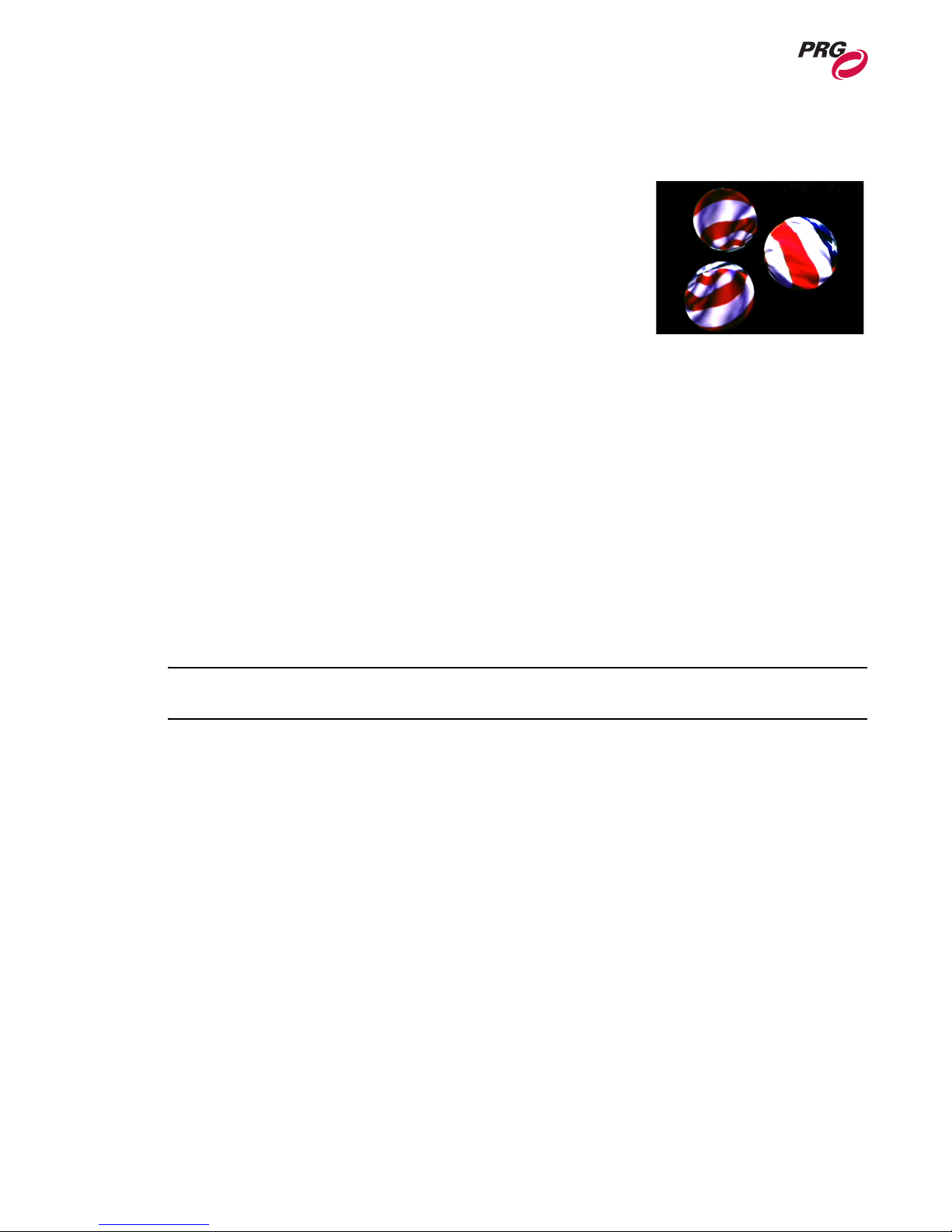
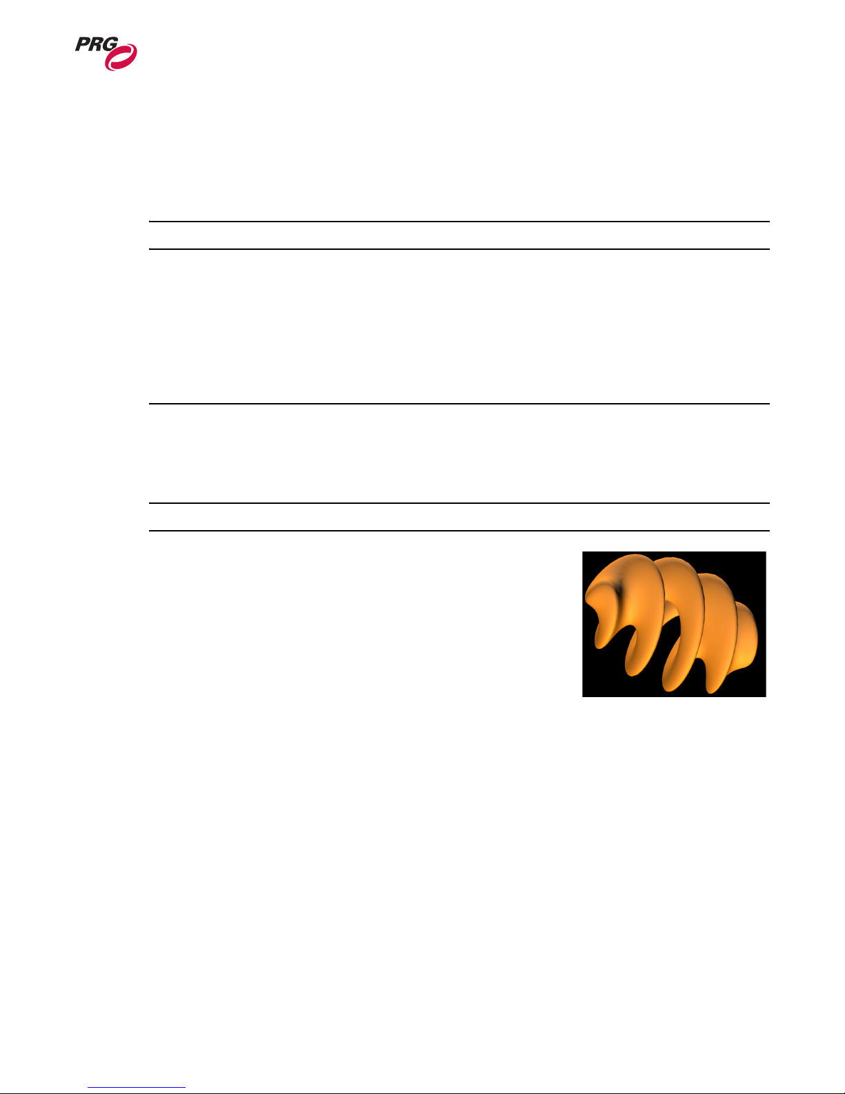
Sample 3D Objects
with Flag Texture
Effects
The Mbox Extreme Media Server includes a set of pre-designed effect elements. Effects such as color,
tint and alpha adjustment can be applied to any Background or 3D Object.
Refer to “Texture Effects” on page 62 and for a complete list of available effects.
Note: Effects override transitions. If any effects are active, then the transition will be limited to
dissolve (or snap, if effect is processor intensive).
Applying an effect to a Background using DMX512 control:
Step 1. Using Background layer created in the previous section, set Effect channel at a value
between 0-255.
Step 2. Use Effect control channels to modify how the effect is applied.
Transitions
Transitions can be used to create video switcher style dissolves and wipes when performing timed
crossfades between still images or movies. Transitions between two Backgrounds or Object textures
can also be applied, along with an associated timing parameter. For example, it would be possible to
create a timed crossfade on a single Background layer.
Refer to “Transitions” on page 63 for a complete list of available transitions.
Applying a transition using DMX512 control:
• Using Background layer created in the previous section, set Transition (XFade Type) channel at a
value between 0-255.
• Set XFade Timing value to 3 seconds.
28 02.9800.0001
Page 37

OPERATION : MBOX EXTREME ENVIRONMENT
3
Play Modes
Play modes can be used to create both In/Out and Random/Stop frames for media playback. Refer to
“Play Modes” on page 60 for Play mode DMX512 mappings.
In and Out Frame
The In and Out Frame feature provides a method for setting a start and stop frame for a video clip in
order to loop between two points. Like the Effects and Transitions feature, the In/Out frame can be
applied to Background or Object textures.
To set In/Out frames using DMX512 control:
Step 1. Set Play mode to value between 80-89.
Step 2. Adjust In Frame to desired in point.
Step 3. Set Play mode to value between 90-99.
Step 4. Adjust Out frame to desired out point.
Step 5. Set Play mode to 0 for Forward Loop playback.
Random and Stop
The Random feature provides a method for playing frames in random order. The Stop feature halts
play.
To play frames in random order:
• Set encoder at a value between 60-69.
To stop play:
• Set play speed to 0.
Live Video Input
The Mbox Extreme Media Server supports two separate live video inputs from FireWire® video
devices and the SDI video capture card installed in the Macintosh® G5 computer. The live video is
displayed on an available background.
To control live video:
Step 1. Set Texture Library channel to 255.
Step 2. Set Background to 254 (Local Camera 2) or 255 (Local Camera 1).
Note: If no camera is connected and Diagnostics are enabled, a "No Camera" image appears on the
display.
02.9800.0001 29
Page 38
MBOX EXTREME™ MEDIA SERVER USER MANUAL
3D Objects
The Mbox Extreme Environment includes up to five 3D Objects. Parameters such as shape,
transparency level, texture, color and scale can be configured for each, independently, to create
dynamic or stationary objects within your virtual scenery. These Objects - unlike the Backgrounds can interact in a 3-dimensional space, which means that there is no set order to their appearance. In
other words, Object 1 can move in front or behind Object 2, Object 2 can move in front or behind
Object 3, and so on. Objects such as a sphere or square could then be scaled, texturized and positioned
to create dynamic scenery.
In order to provide access to the models using DMX512 control, both the library folders and models
are named with a DMX512 value (from 000 to 255). When accessing a model using DMX512 control,
you would first provide the library number, then the model number. The Mbox Extreme Media Server
provides 10 pre-loaded object models located in Library folder 001. (For more information on the
folder/file structure, see “Content Management” on page 41.)
All 3D Objects have the following controllable elements:
• Transparency
• Shape
•Texture
• Color
• X, Y, Z Position
• X, Y, Z Scale
• X, Y, Z Rotation (Spin)
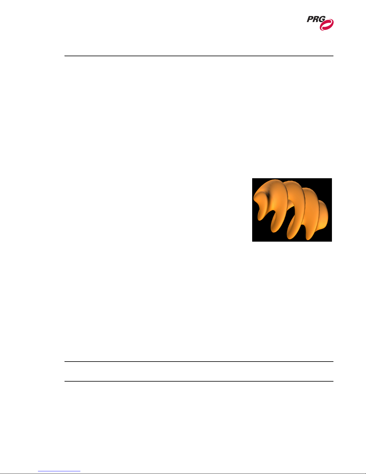
Sample 3D Object with
Background and Lighting
• Texture Effect
• Shape XFade time
Just like a prop on a stage, 3D Objects (models) require illumination from either the ambient and/or
spot light channels to be visible. In addition, each object has its own intensity control, which controls
its overall transparency. For example, set the ambient light to 40%, then choose an object channel, set
its intensity to full and use the Model Library and object channels to choose a model. Use scale to
increase the size of a model as required.
You can also apply textures to a model by selecting the "Object Texture" channel and choosing a
texture from the library. For more information, see “Textures” on page 28.
Displaying a 3D Object using DMX512 control:
Step 1. Set Camera Intensity to value 255.
Note: The Camera Intensity channel controls the built-in dimmer on the I/O module. If this channel is
set to 0, no output will appear on the output device.
Step 2. Select at least one Ambient light or Spot light channel and set Intensity to desired level.
Step 3. Select Texture 1 and Object 1 channels. Set Transparency to full (255). A white square will
appear on display.
Step 4. Deselect Texture 1 channel, so that only Object 1 channel is selected.
30 02.9800.0001
Page 39
OPERATION : MBOX EXTREME ENVIRONMENT
Step 5. Set Shape Library channel to a value between 000-255. This determines the folder for the
model.
Step 6. Set Shape channel to a value between 000-255. This determines the file for the model.
Step 7. Adjust desired parameters for the Texture as desired.
Note: Some control parameters for 3D models are located in the Texture channels.
Applying a Texture to a 3D Object using DMX512 control:
Step 1. Use 3D object created in previous section.
Step 2. Select Texture 1 channel.
Step 3. Set Library and Texture channels to desired values. Texture appears on the surface of the 3D
Object.
3
3D Lighting
The Mbox Extreme Environment includes five separate Lighting Elements: one ambient source and
four directional spots. These Lighting Elements provide illumination for the 3D Objects.
Note: Lighting elements have no effect on Backgrounds.
The ambient light source applies to the overall Mbox Extreme
Environment. This is a uniform field of light which is not subject
to shadows or other directional limitations.
The directional spot lights on the other hand, provide directional
illumination in order to give the 3D Objects their 3-dimensional
look. This lighting will create the shadows necessary for depth.
The spot lights originate as follows:
• Spot Light 1 - from upper right.
• Spot Light 2 - from upper left.
• Spot Light 3 - from below.
• Spot Light 4 - from above.
All Lights have the following controllable elements:
• Intensity
• Color (RGB mixing)
Sample 3D Object with
Background and Lighting
02.9800.0001 31
Page 40

MBOX EXTREME™ MEDIA SERVER USER MANUAL
Camera
The Mbox Extreme Environment includes one Camera element. This element performs two main
functions:
• Master Intensity control of Mbox Extreme I/O Module.
Note: The Camera Intensity channel must be greater than 0 to view any output from the Mbox
Extreme I/O Module.
• Modifies the viewpoint of the 3D Objects and Backgrounds.
Camera parameters, such as orbit, dolly, field of view, shutters and keystone correction, can be
controlled in order to fully customize the look of your scenery.
The Camera has the following controllable elements:
• Intensity
• Color
•Orbit X
•Orbit Y
• Dolly - distance of the camera to the Environment.
• Camera Roll and Spin
• Field of View - overall viewing angle of the Environment. This is the equivalent of using different
"virtual camera lenses," such as wide angle, telephoto, etc.
•Pitch
•Yaw
•Two effects
• Mbox Extreme Control Channels
One final thing to note in regards to Camera position is that it is always in set relation to the
Backgrounds. If the Camera position is orbited upwards, then the Backgrounds are orbited downwards
in an equal ratio. This will ensure that the Background elements are always in view.
Control Channels
The Camera Control Channel element controls on-board diagnostic screens and special functions for
the Mbox Extreme Media Server. For more information, see “Control Channels” on page 59.
32 02.9800.0001
Page 41

OPERATION : MBOX EXTREME ENVIRONMENT
3
Shutter
Shutter parameters offer the ability to shape a layer. Shutters can be positioned, scaled, and rotated. To
activate the Shutter, the Shutter Shape channel must be set to a value other than the default.
Shutter have the following controllable elements:
• Shutter Shapes
• Shutter X
• Shutter Y
• Shutter Color
• Shutter Scale
• Shutter Edge
• Shutter Rotation
For more information, see “Shutter” on page 51 and “Shutter Shapes” on page 59.
Keystone
Keystone parameters offer a type of geometrical distortion that causes a normally rectangular image to
be displayed as a trapezoidal image. This can occur when the Environment is projected at an odd angle
to the flat surface it is being projected upon. The Keystone controls provide a way to correct this
distortion.
Keystone has the following controllable elements:
• Keystone X
• Keystone Y
• Keystone Scale
• Keystone Skew
• Tiling
• Edge Blending
For more information, see “Keystone” on page 52 and “Tiling Modes” on page 61.
02.9800.0001 33
Page 42
MBOX EXTREME™ MEDIA SERVER USER MANUAL
Application Window
Overview
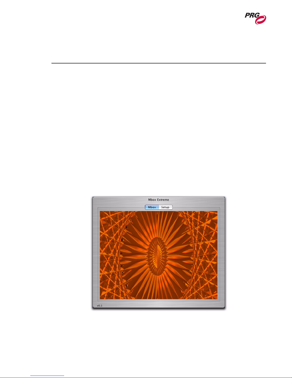
The Mbox Extreme Media Server contains the Mbox Extreme software application. The Mbox
Extreme application window allows you to view the Mbox Extreme Media Server output in either
window or full screen mode on the local monitor.
The application window contains two screens:
• Mbox Output window.
• Setup window.
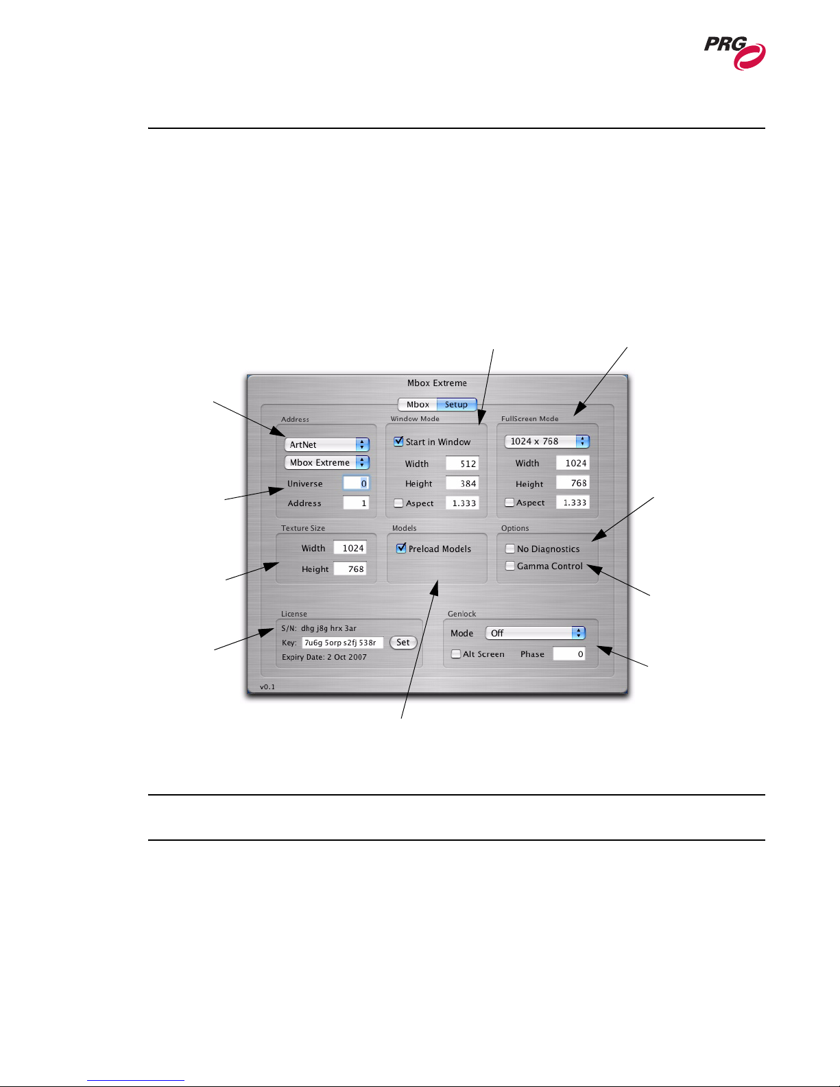
The Setup window is used to:
• Set DMX512 or Art-Net address for this media server.
• Set application default to start in window mode and specify window size.
• Set application default resolution when starting in full screen mode.
• Set texture size.
• Set 3D models preload default.
• Configure other options.
• Input License Key to authorize the application.
Figure 3-3: Mbox Extreme Application Main Window
34 02.9800.0001
Page 43
OPERATION : APPLICATION WINDOW
3
Starting the Mbox Extreme Application
The Mbox Extreme application will start automatically when the computer is turned on. If the
application does not start automatically, locate the Mbox Extreme icon on the Apple Dock and click
once.
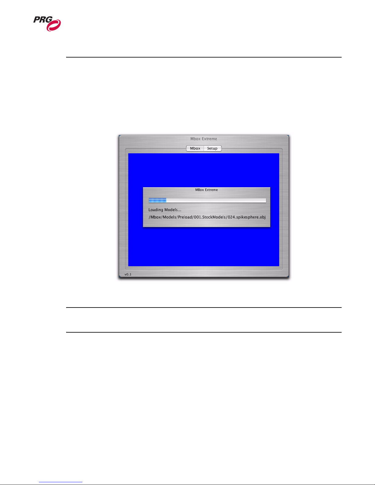
When starting the application, the default is to preload all 3D models. While 3D models are loading,
the computer will be locked and the Mbox Extreme application window appears with a blue screen and
progress bar (Figure 3-4).
Figure 3-4: Mbox Extreme Startup Window
Note: The application can also be launched without loading 3D models by pressing the b key
while clicking on the Mbox Extreme icon.
The Mbox and Setup buttons allow you to switch between the Mbox Preview window and the Setup
window. For more information on the Setup window, see “Setup Window” on page 36.
02.9800.0001 35
Page 44
MBOX EXTREME™ MEDIA SERVER USER MANUAL
Setup Window
The Setup window allows you to configure parameters for the individual Mbox Extreme Media Server.
This Setup window only appears when viewing the Mbox Extreme application in window mode.
To open the Setup window:
Step 1. Start the Mbox Extreme application. For more information, see “Starting the Mbox Extreme
Application” on page 35.
Step 2. At top of application window, press Setup button.
Select Data Input Type
Set Mbox Extreme Address
Set Texture Size
Set License Key
Set Window Mode
Preferences
Set Full-Screen
Mode Preferences
Set Diagnostics
Preferences
(Strongly recommmend this option
be checked in show
settings.)
Set Gamma Control
(Not recommended
without prior instruction
from PRG)
Set Genlock
Sychronization
(not yet implemented)
Step 3. Configure preferences.
Note: When changing texture size preferences, you must quit the application and restart for changes to
take effect.
36 02.9800.0001
Set 3D Object
Preload Preferences
Page 45
OPERATION : APPLICATION WINDOW
3
Changing the Application Window Size
The Mbox Extreme application window opens in either window or full-screen mode depending on the
settings specified in the Setup window. Set “Setup Window” on page 36.
To change window size:
• Press
b / [F] to toggle between full-screen and window mode.
Closing the Application
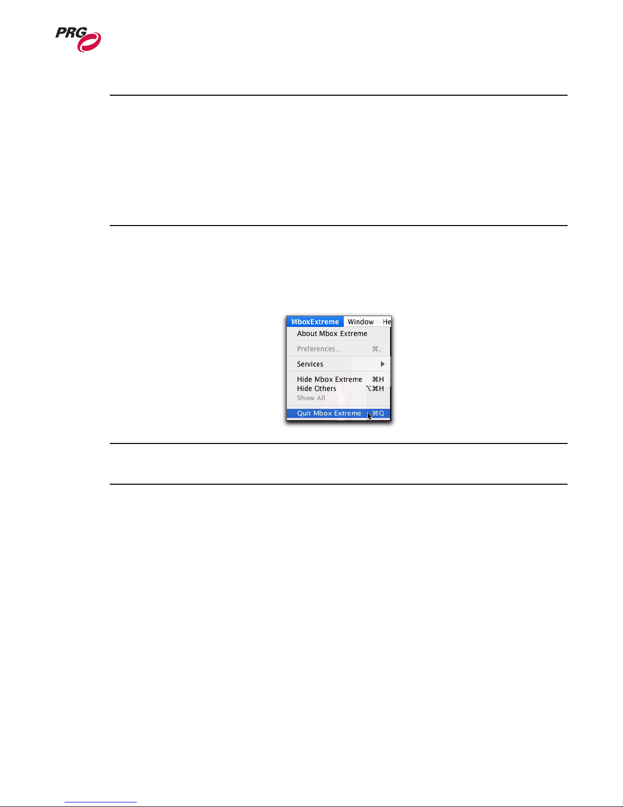
To close and quit the Mbox Extreme application, press b / [Q] or select Quit Mbox Extreme from
the Mbox Extreme menu.
Note: If the Mbox Extreme application window is in full-screen mode, press b / [F] to minimize
screen to access the Mbox Extreme menu.
02.9800.0001 37
Page 46

MBOX EXTREME™ MEDIA SERVER USER MANUAL
Notes
38 02.9800.0001
Page 47

4.
Media Content
This chapter provides instructions for managing media files which reside on the Mbox Extreme
Media Server and for adding your own custom content.
• Content Type
• Content Management
02.9800.0001 39
Page 48

MBOX EXTREME™ MEDIA SERVER USER MANUAL
Content Type
Images and Video Clips
The Mbox Extreme Media Server supports Apple ® QuickTime® technology for rendering and
playback of images and video files. The following file types are supported:
• TIF - still image file
• TIFF - still image file
• TARGA - still image with alpha component
• JPEG - still image file
• JPG - still image file
• MOV - QuickTime movie file
• VID - QuickTime movie file from a video source
• JPG_M - QuickTime movie file containing a still image
• NULL - used to create a small zero-alpha black image. This image is useful when using
transitions.
Note: File extensions are not case-sensitive. For example, files with extension .JPG and .jpg are the
same.
Recommended Codecs
JPEG and TIFF file types are recommended for creating still image content for optimum output on the
Mbox Extreme Media Server. For movie content, PHOTO JPEG (medium quality) is the
recommended file type for optimum playback. If you have questions regarding media file types, please
contact the PRG Dallas office at 214.630.1963.
Note: The Mbox Extreme media server will play other QuickTime file types, but they may not load as
quickly or play as smoothly as the recommended file type. All custom content should be created in a
single common format. The PHOTO JPEG codec is strongly recommended.
3D Models (Objects)
Custom 3D models can be added to the Mbox Extreme Media Server. The Mbox Extreme Media
Server supports the Alias|Wav efront™ 3D .obj format. There are several third-party applications that
can export files to this format, including Maya®, Poser®, Bryce® and Cheetah3D to name a few.
40 02.9800.0001
Page 49
Content Management
Overview
The Mbox Extreme Media Server offers a flexible media folder structure. Media can reside locally on
the Mbox Extreme server hardrive or on additional hardrives or storage devices connected to the
Macintosh® G5 computer.
At startup, the Mbox Extreme application performs a media scan to search all folders that reside within
the /Mbox/Media folder that resides on the main hardrive of the Mbox Extreme Media Server.
Additional media can be attached to the main /Mbox/Media folder through aliases. Aliases must be
linked to folders on the supplemental media, it cannot be aliased to files. Also, an alias cannot refer to
another alias. The main /Mbox and /Mbox/Media folder must reside on the local hardrive and cannot
be aliases.
Note: The initial media scan allows for the locations of files to be resolved at startup, therefore the
"distance" of a file from the main folder has no effect on the time required to find a file.
MEDIA CONTENT : CONTENT MANAGEMENT
4
Each time the Mbox Extreme Media Server completes a media scan, a text file is created with all
media files found and their corresponding combined file numbers. The text file can be found at /Mbox/
MboxExtreme_Media_List.txt
CAUTION: All media content on the Mbox Extreme media server should be backed-up to an external
drive.
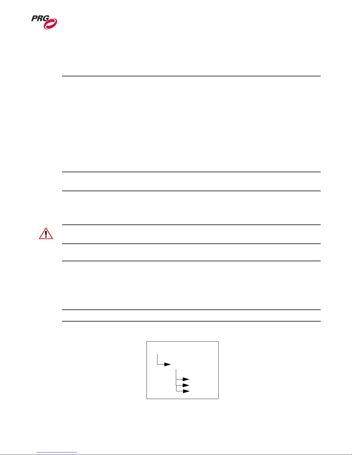
Folder and File Numbering
Video and image files are located within the /Mbox/Media folder on the Mbox Extreme main hardrive.
They are arranged into individual "Library" folders. Each folder must be named beginning with a
unique 3-digit index value between 001 and 254.
Note: The Library folder beginning with 255 is reserved for live video access commands.
In turn, each file within the Library folder must contain a 3-digit index value between 000 to 255.
Mbox/media
001.videos
02.9800.0001 41
001.rain
002.drops
etc.
Page 50
MBOX EXTREME™ MEDIA SERVER USER MANUAL
The Mbox Extreme Media Server also supports 16-bit file numbers. When a file contains a 16-bit
number, the folder number is the upper 8 bits of the 16-bit number. The folder number of any parent
folders is ignored.
Note: When using 16-bit file numbers, the file number does not get updated when moved to another
folder.
Preloaded Content
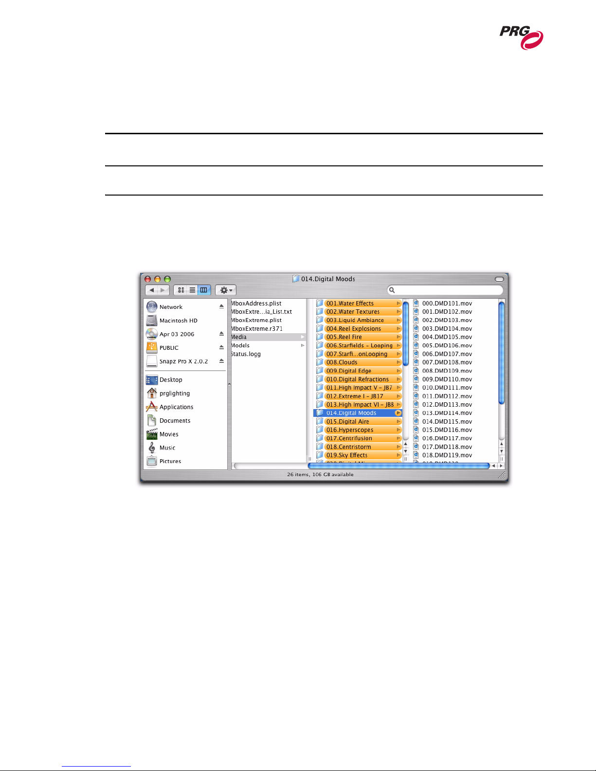
The Mbox Extreme Media Server comes with preloaded stock images and movies contained in 41
folders contained in the /Mbox/Media folder. (Preloaded content is subject to change.)
Users can create additional folders to add additional content. Also, Preloaded content can be deleted, if
necessary, but this is not recommended.
42 02.9800.0001
Figure 4-1: Mbox Extreme Media Folder
Page 51

MEDIA CONTENT : CONTENT MANAGEMENT
Adding Video and Image Files
Note: You must rescan the media folders or restart the Mbox Extreme application any time you add
content to the Mbox Extreme Media Server. To rescan the media, use the Rescan Media Library
Control Channel on the Camera Fixture. For more information, see “Control Channels” on page 59.
To add video and/or image files:
Step 1. Open /Mbox/Media folder located on the main hardrive.
Step 2. At File menu, select "New Folder" and enter a unique 3-digit number (that is not already
being used) followed by a descriptive name. For example, "001.mycontentfolder."
Step 3. Copy image and/or video files into the new folder.
Step 4. For each file, add a unique 3-digit index value to each file (between 0-255) along with a
descriptive name. For example, "001.earth", "002.wind", "003.fire", etc.
Note: When adding files, it is recommended that users create new unique folder numbers.
4
Adding 3D Objects
3D models are located in the Mbox/Models and Mbox/Models/Preload folders. Models located in the
Preload folder are preloaded at startup and appear on the display more rapidly when called. Models
must be numbered 000-255 and placed in folders numbered 001-255. Folder 000 is reserved by the
system and should not be used.
Note: You must restart the Mbox Extreme application any time you add 3D content to the Mbox
Extreme Media Server.
To add 3D object files:
Step 1. Open Mbox/Models.
Step 2. At File menu, select "New Folder" and enter a unique 3-digit number (that is not already
being used) followed by a descriptive name. For example, "001 mymodels."
Step 3. Copy model files into the new folder.
Step 4. For each file, add a unique 3-digit index value to each file (between 0-254) along with a
descriptive name. For example, "001.man", "002.hammer", "003.airplane", etc.
02.9800.0001 43
Page 52

MBOX EXTREME™ MEDIA SERVER USER MANUAL
Notes
44 02.9800.0001
Page 53

5.
Troubleshooting and
Maintenance
This chapter procedures for extended care of the Mbox Extreme Media Server.
• Routine Maintenance
02.9800.0001 45
Page 54
MBOX EXTREME™ MEDIA SERVER USER MANUAL
Routine Maintenance
Cleaning or Replacing the Air Filter
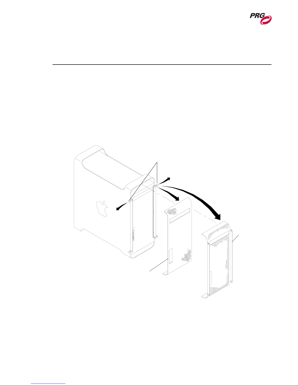
The air filters, located at front of the Macintosh® G5 computer, should be cleaned or replaced as
needed.
To clean/remove air filter:
Step 1. At computer, pull four screw pins to release grill.
Step 2. Remove grill and air filter.
Step 3. Clean filter with compressed air (or water, if allowed to fully dry).
Step 4. Re-install.
Spring Pins
Grill
Air Filter
Figure 5-1: Mac G5 Computer Air Filter Removal
46 02.9800.0001
Page 55

TROUBLESHOOTING AND MAINTENANCE : ROUTINE MAINTENANCE
5
Removing Computer from Case
The Macintosh® G5 computer can be removed from the case to be cleaned or replaced. Two
configurations of the Mbox Extreme case exist: one case contains two mounting brackets that attach to
the computer and the other contains only foam encasing the computer.
To remove Mac G5 computer with mounting brackets:
Step 1. At rear of case, disconnect all cables from Mac G5 computer.
Step 2. At front of case, remove four 8mm mounting bracket screws.
Step 3. At rear of case, remove four 8mm mounting bracket screws.
Step 4. Carefully slide Mac G5 computer through front of case.
To remove Mac G5 computer with foam-only mounting:
Step 1. At rear of case, disconnect all cables from Mac G5 computer.
Step 2. Carefully slide Mac G5 computer through front of case.
02.9800.0001 47
Page 56

MBOX EXTREME™ MEDIA SERVER USER MANUAL
Notes
48 02.9800.0001
Page 57

A.
DMX Channel Mapping
This Appendix contains tables for the combined DMX512 channel map as well as additional
controls such as play modes, tiling, shutter shapes, aspect control, blending control, texture effect,
transitions, and built-in shapes.
02.9800.0001 49
Page 58
MBOX EXTREME™ MEDIA SERVER USER MANUAL
DMX Operation
Channel Mapping
Combined DMX Channel Map
Table A-1: Mbox Extreme Combined DMX Channel Map
Channel Function Default Notes
Ambient Light
1 Intensity 0
2 Red 255
3 Green 255
4 Blue 255
Spot Light 1
5 Intensity 0
6 Red 255
7 Green 255
8 Blue 255
Spot Light 2
9 Intensity 0
10 Red 255
11 Green 255
12 Blue 255
Spot Light 3
13 Intensity 0
14 Red 255
15 Green 255
16 Blue 255
Spot Light 4
17 Intensity 0
18 Red 255
19 Green 255
20 Blue 255
Camera
21 Intensity 255 Overall dimming provided by
22 Red 255
23 Green 255
24 Blue 255
25 Orbit X course 127
26 Orbit X fine 255
27 Orbit Y course 127
hardware
50 02.9800.0001
Page 59
DMX CHANNEL MAPPING : DMX OPERATION
Table A-1: Mbox Extreme Combined DMX Channel Map (Continued)
28 Orbit Y fine 255
29 Dolly course 127
30 Dolly fine 255
31 Roll course 127
32 Roll fine
33 Spin 127
34 Field of View course 127
35 Field of View fine 255
36 Pitch course 127
37 Pitch fine 255
38 Yaw course 127
39 Yaw fine 255
40 Effect 1 0 See Texture Effects
41 Effect Control 1a 0
42 Effect Control 1b 0
43 Effect 2 0 See Texture Effects
44 Effect Control 2a 0
45 Effect Control 2b 0
46 Control 0 See Control Channels
Shutter
47 Shape 255
48 Shutter X course 127
49 Shutter X fine 255
50 Shutter Y course 127
51 Shutter Y fine 255
52 Red 0
53 Green 0
54 Blue 0
55 Shutter Scale course 255
56 Shutter Scale fine 255
57 Shutter Edge 0
58 Shutter 1a 0 See Control Channels
59 Shutter 1b 0
60 Shutter 2a 0
61 Shutter 2b 0
62 Shutter 3a 0
63 Shutter 3b 0
64 Shutter 4a 0
65 Shutter 4b 0
66 Shutter Rotation 127
A
02.9800.0001 51
Page 60
MBOX EXTREME™ MEDIA SERVER USER MANUAL
Table A-1: Mbox Extreme Combined DMX Channel Map (Continued)
Keystone
67 Edge Blending Enable 0 0-9 Narrow, 10-19 Med,
68 Keystone X course 127
69 Keystone X fine 255
70 Keystone Y course 127
71 Keystone Y fine 255
72 Tile Mode 0 See Tiling Modes
73 Tile Overlap 0
74 Scale course 255
75 Scale fine 255
76 Edge 1 0 Edge blending - Top
77 Edge 2 0 Edge blending - Left
78 Edge 3 0 Edge blending - Bottom
79 Edge 4 0 Edge blending - Right
80 Corner 1 - X 0
81 Corner 1 - Y 0
82 Corner 2 - X 0
83 Corner 2 - Y 0
84 Corner 3 - X 0
85 Corner 3 - Y 0
86 Corner 4- X 0
87 Corner 4- Y 0
88 Keystone Rotation 127
Object 1 - Texture
89 Transparency 0
90 X Position course 127
91 X Position fine 255
92 Y Position course 127
93 Y Position fine 255
94 Red 255
95 Green 255
96 Blue 255
97 Z Position course 127
98 Z Position fine 255
99 Scale course 127
100 Scale fine 255
101 Library 0
102 Texture 0
103 Play Mode 0 See Play Modes
104 Play Speed 127
105 In Frame course 0
106 In Frame fine 0
107 Out Frame course 255
20-255 Wide
52 02.9800.0001
Page 61
DMX CHANNEL MAPPING : DMX OPERATION
Table A-1: Mbox Extreme Combined DMX Channel Map (Continued)
108 Out Frame fine 255
109 Aspect 0 See Aspect Control
110 Blending 255 See Blending Control
111 Effect 1 0 See Texture Effects
112 Effect Control 1a 0
113 Effect Control 1b 0
114 Effect 2 0 See Texture Effects
115 Effect Control 2a 0
116 Effect Control 2b 0
117 XFade Type 0 See Transitions
118 XFade Timing 0
Object 1 - Object
119 Transparency 0
120 Shape Library 0
121 Shape 0 See Built-In Shapes
122 Shape XFade Time 0
123 Anim Speed 127
124 X Scale course 127
125 X Scale fine 255
126 Y Scale course 127
127 Y Scale fine 255
128 Z Scale course 127
129 Z Scale fine 255
130 X Rotation course 127
131 X Rotation fine 255
132 Y Rotation course 127
133 Y Rotation fine 255
134 Z Rotation course 127
135 Z Rotation fine 255
136 X Spin 127
137 Y Spin 127
138 Z Spin 127
139 Effect 1 0
140 Effect Control 1a 0
141 Effect Control 1b 0
Object 2 - Texture
142 Transparency 0
143 X Position course 127
144 X Position fine 255
145 Y Position course 127
146 Y Position fine 255
147 Red 255
148 Green 255
A
02.9800.0001 53
Page 62

MBOX EXTREME™ MEDIA SERVER USER MANUAL
Table A-1: Mbox Extreme Combined DMX Channel Map (Continued)
149 Blue 255
150 Z Position course 127
151 Z Position fine 255
152 Scale course 127
153 Scale fine 255
154 Library 0
155 Texture 0
156 Play Mode 0 See Play Modes
157 Play Speed 127
158 In Frame course 0
159 In Frame fine 0
160 Out Frame course 255
161 Out Frame fine 255
162 Aspect 0 See Aspect Control
163 Blending 255 See Blending Control
164 Effect 1 0 See Texture Effects
165 Effect Control 1a 0
166 Effect Control 1b 0
167 Effect 2 0 See Texture Effects
168 Effect Control 2a 0
169 Effect Control 2b 0
170 XFade Type 0 See Transitions
171 XFade Timing 0
Object 2 - Object
172 Transparency 0
173 Shape Library 0
174 Shape 0 See Built-In Shapes
175 Shape XFade Time 0
176 Anim Speed 127
177 X Scale course 127
178 X Scale fine 255
179 Y Scale course 127
180 Y Scale fine 255
181 Z Scale course 127
182 Z Scale fine 255
183 X Rotation course 127
184 X Rotation fine 255
185 Y Rotation course 127
186 Y Rotation fine 255
187 Z Rotation course 127
188 Z Rotation fine 255
189 X Spin 127
190 Y Spin 127
54 02.9800.0001
Page 63
DMX CHANNEL MAPPING : DMX OPERATION
Table A-1: Mbox Extreme Combined DMX Channel Map (Continued)
191 Z Spin 127
192 Effect 1 0
193 Effect Control 1a 0
194 Effect Control 1b 0
Object 3- Texture
195 Transparency 0
196 X Position course 127
197 X Position fine 255
198 Y Position course 127
199 Y Position fine 255
200 Red 255
201 Green 255
202 Blue 255
203 Z Position course 127
204 Z Position fine 255
205 Scale course 127
206 Scale fine 255
207 Library 0
208 Texture 0
209 Play Mode 0 See Play Modes
210 Play Speed 127
211 In Frame course 0
212 In Frame fine
213 Out Frame course 255
214 Out Frame fine 255
215 Aspect 0 See Aspect Control
216 Blending 255 See Blending Control
217 Effect 1 0 See Texture Effects
218 Effect Control 1a 0
219 Effect Control 1b 0
220 Effect 2 0 See Texture Effects
221 Effect Control 2a 0
222 Effect Control 2b 0
223 XFade Type 0 See Transitions
224 XFade Timing 0
Object 3 - Object
225 Transparency 0
226 Shape Library 0
227 Shape 0 See Built-In Shapes
228 Shape XFade Time 0
229 Anim Speed 127
230 X Scale course 127
231 X Scale fine 255
A
02.9800.0001 55
Page 64
MBOX EXTREME™ MEDIA SERVER USER MANUAL
Table A-1: Mbox Extreme Combined DMX Channel Map (Continued)
232 Y Scale course 127
233 Y Scale fine 255
234 Z Scale course 127
235 Z Scale fine 255
236 X Rotation course 127
237 X Rotation fine 255
238 Y Rotation course 127
239 Y Rotation fine 255
240 Z Rotation course 127
241 Z Rotation fine 255
242 X Spin 127
243 Y Spin 127
244 Z Spin 127
245 Effect 1 0
246 Effect Control 1a 0
247 Effect Control 1b 0
Object 4 - Texture
248 Transparency 0
249 X Position course 127
250 X Position fine 255
251 Y Position course 127
252 Y Position fine 255
253 Red 255
254 Green 255
255 Blue 255
256 Z Position course 127
257 Z Position fine 255
258 Scale course 127
259 Scale fine 255
260 Library 0
261 Texture 0
262 Play Mode 0 See Play Modes
263 Play Speed 127
264 In Frame course 0
265 In Frame fine
266 Out Frame course 255
267 Out Frame fine 255
268 Aspect 0 See Aspect Control
269 Blending 255 See Blending Control
270 Effect 1 0 See Texture Effects
271 Effect Control 1a 0
272 Effect Control 1b 0
273 Effect 2 0 See Texture Effects
56 02.9800.0001
Page 65
DMX CHANNEL MAPPING : DMX OPERATION
Table A-1: Mbox Extreme Combined DMX Channel Map (Continued)
274 Effect Control 2a 0
275 Effect Control 2b 0
276 XFade Type 0 See Transitions
277 XFade Timing 0
Object 4- Object
278 Transparency 0
279 Shape Library 0
280 Shape 0 See Built-In Shapes
281 Shape XFade Time 0
282 Anim Speed 127
283 X Scale course 127
284 X Scale fine 255
285 Y Scale course 127
286 Y Scale fine 255
287 Z Scale course 127
288 Z Scale fine 255
289 X Rotation course 127
290 X Rotation fine 255
291 Y Rotation course 127
292 Y Rotation fine 255
293 Z Rotation course 127
294 Z Rotation fine 255
295 X Spin 127
296 Y Spin 127
297 Z Spin 127
298 Effect 1 0
299 Effect Control 1a 0
300 Effect Control 1b 0
Object 5- Texture
301 Transparency 0
302 X Position course 127
303 X Position fine 255
304 Y Position course 127
305 Y Position fine 255
306 Red 255
307 Green 255
308 Blue 255
309 Z Position course 127
310 Z Position fine 255
311 Scale course 127
312 Scale fine 255
313 Library 0
314 Texture 0
A
02.9800.0001 57
Page 66
MBOX EXTREME™ MEDIA SERVER USER MANUAL
Table A-1: Mbox Extreme Combined DMX Channel Map (Continued)
315 Play Mode 0 See Play Modes
316 Play Speed 127
317 In Frame course 0
318 In Frame fine
319 Out Frame course 255
320 Out Frame fine 255
321 Aspect 0 See Aspect Control
322 Blending 255 See Blending Control
323 Effect 1 0 See Texture Effects
324 Effect Control 1a 0
325 Effect Control 1b 0
326 Effect 2 0 See Texture Effects
327 Effect Control 2a 0
328 Effect Control 2b 0
329 XFade Type 0 See Transitions
330 XFade Timing 0
Object 5- Object
331 Transparency 0
332 Shape Library 0
333 Shape 0 See Built-In Shapes
334 Shape XFade Time 0
335 Anim Speed 127
336 X Scale course 127
337 X Scale fine 255
338 Y Scale course 127
339 Y Scale fine 255
340 Z Scale course 127
341 Z Scale fine 255
342 X Rotation course 127
343 X Rotation fine 255
344 Y Rotation course 127
345 Y Rotation fine 255
346 Z Rotation course 127
347 Z Rotation fine 255
348 X Spin 127
349 Y Spin 127
350 Z Spin 127
351 Effect 1 0
352 Effect Control 1a 0
353 Effect Control 1b 0
58 02.9800.0001
Page 67
DMX CHANNEL MAPPING : DMX OPERATION
Control Channels
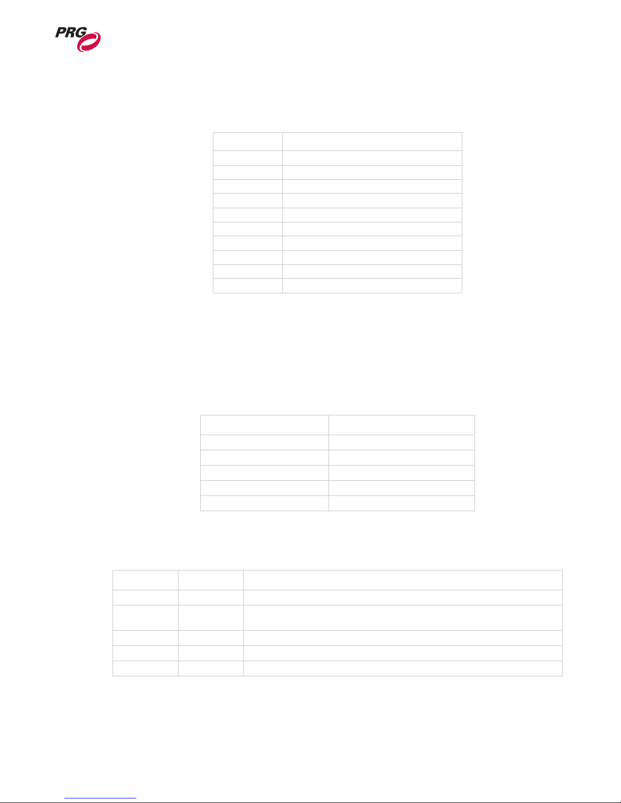
Table A-2: Control Channels
Value Type
0-9 none
10-19 Version HUD
40-49 Lights/Camera/Shutter/Keystone HUD
50-59 Objects HUD
240 Rescan Media Library*
241 Enable SDI output controls**
250 Quit Application*
251 Shutdown Computer*
252 Restart Computer*
253 Restart Application*
* Special commands require that the DMX512 value be held for three seconds, followed by an immediate change to
DMX value 0 without any other values in between.
** When the control channel stays at this value for three seconds, the shutter controls are mapped to the SDI Configura-
tion for Shutter Control. The configuration values are stored by the Mbox Extreme application. Change the control
channel value to restore normal shutter functions. Video card gamma works in all full screen modes - not just SDI.
A
SDI Shutter Control
Table A-3: SDI Configuration for Shutter Control
Shutter Control SDI Configuration
Shutter 1a Red Channel Gain
Shutter 1b Green Channel Gain
Shutter 2a Blue Channel Gain
Shutter 2b Black Level
Shutter 3a Video Card Gamma
Shutter Shapes
Table A-4: Shutter Shapes
Value Shap e Note s
0-9 Disabled
10-19 Moving Light
Mode
20-29 Leko Mode Distance and angle controls. If distance is zero, shutter disappears.
30-39 Iris Mode A round Iris. Scale is magnified to enclose the screen. No other controls.
40-49 Blob Mode A Bezier curve is drawn touching the midpoints of the rectangle formed by Leko mode.
Separate controls for each end of shutter. If both controls are zero, shutter disappears.
02.9800.0001 59
Page 68
MBOX EXTREME™ MEDIA SERVER USER MANUAL
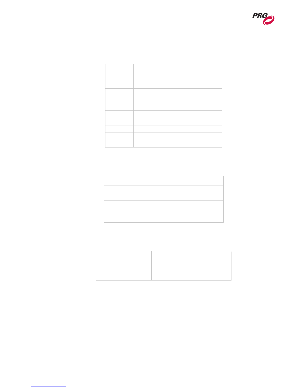
Play Modes
Val ue Fu nct ion
0-9 Forward Loop
10-19 Reverse Loop
20-29 Forward Once
30-39 Reverse Once
40-49 Forward Bounce
50-59 Reverse Bounce
60-69 Random
70-79 Forward Once - Restart on In Frame Change
80-89 Scrub - In Frame
90-99 Scrub - Out Frame
Aspect Control
Table A-5: Play Modes
Blending Control
Table A-6: Aspect Control
Value Mode
0 Square Pixels
1-254 Ratios scaling from 1:4 to 4:1
74 4:3 ratio
104 16:9 ratio
255 Fit to Screen mode
Table A-7: Blending Control
Value Mo de
0 No blending or Blend Time = 0
1-255 Variable blend time, as a proportion of the
frame time.
60 02.9800.0001
Page 69

Tiling Modes
DMX CHANNEL MAPPING : DMX OPERATION
Table A-8: Tiling Modes
Val ue Mode
0 Tiling Disabled
1 2x2 - 1of 4
2 2x2 - 2 of 4
3 2x2 - 3 of 4
4 2x2 - 4 of 4
5 3x3 - 1 of 9
6 3x3 - 2 of 9
7 3x3 - 3 of 9
8 3x3 - 4 of 9
9 3x3 - 5 of 9
10 3x3 - 6 of 9
11 3x3 - 7 of 9
12 3x3 - 8 of 9
13 3x3 - 9 of 9
14 4x4 - 1 of 16
15 4x4 - 2 of 16
16 4x4 - 3 of 16
17 4x4 - 4 of 16
18 4x4 - 5 of 16
19 4x4 - 6 of 16
20 4x4 - 7 of 16
21 4x4 - 8 of 16
22 4x4 - 9 of 16
23 4x4 - 10 of 16
24 4x4 - 11 of 16
25 4x4 - 12 of 16
26 4x4 - 13 of 16
27 4x4 - 14 of 16
28 4x4 - 15 of 16
29 4x4 - 16 of 16
A
Note: Tiling positions are in row major order (rows are filled in order). For example, the 3 x 3
arrangement would look appear in the following order:
1 2 3
4 5 6
7 8 9
02.9800.0001 61
Page 70

MBOX EXTREME™ MEDIA SERVER USER MANUAL
Texture Effects
Value Effect Description Control 1 Control 2
0 None No effect
1 Monochrome convert colors to grayscale amount
2 Sepia Tone convert colors to sepia tone image amount
3 Invert color invert
4 Color Reduce reduce color space amount
5 Bright/Contrast brightness and contrast controls brightness contrast
6 Saturation saturation control saturation
7 Hue hue adjustment hue
8 Gamma gamma adjustment gamma
9 Exposure exposure adjustment exposure
10 Solarize solarize effect amount
11 Black & White convert image to black and white threshold
12 Black Alpha dark areas transparent threshold
13 X-Ray inverted grayscale amount
14 Bloom soften edges, add glow radius intensity
15 Gloom dulls highlights radius intensity
16 Sharpen increases image detail by sharpening sharpness
17 Median reduce noise with median calculation
18 Color Switch RGB -> RBG/BGR/GBR/GRB mode intensity
19 Varietal Lines spread single row over vertical space row
20 Color Shift dynamic color shift (sine function) range speed
21 Blur simple/quick image blur amount
22 Gaussian Blur more sophisticated / slow blur amount
23 Circular Screen circular shaped halftone screen width sharpness
24 Dot Screen dot patterned halftone screen width angle
25 Line Screen line patterned halftone screen width angle
26 Hatched Screen hatched patterned halftone screen width angle
27 CMYK Screen color, halftoned screen width angle
28 Tiles image tiling divisions
29 Circular Crop circular image crop with edge blur size edge
30 Rectangular Crop rectangular image crop with edge blur size edge
31 Mirrors various mirror modes mode
32 Horizontal Bars break image into bars number width
33 Vertical Bars break image into bars number width
34 Double Vision offset image and overlay x offset y offset
38 Flicker dynamic flickering effect size speed
39 Shake dynamic shaking effect size speed
Table A-9: Texture Effects
62 02.9800.0001
Page 71
DMX CHANNEL MAPPING : DMX OPERATION
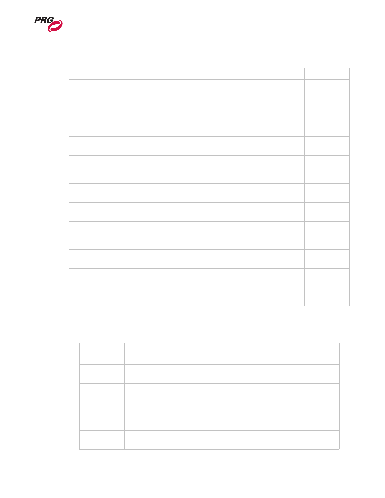
Table A-9: Texture Effects (Continued)
Value Effect Description Control 1 Control 2
40 Wobble dynamic wobbling effect size speed
41 Bump Distortion bump distortion radius scale
42 Hole Hole distortion radius
43 Pinch pinch distortion radius scale
44 Torus torus distortion width
45 Twirl twirl distortion radius scale
46 Vortex vortex distortion radius angle
47 Lozenge lozenge distortion width
48 Edge Work Black & White conversion radius
49 Edge Detect edge detection with color intensity
50 Crystallize break up into crystal pattern radius
51 Pixelate pixelate image scale
52 Pointillize break image into points radius
53 Kaleidoscope geometric distortion angle
54 LED Wall break up into dots dot amount dot size
55 Cartoon cartoon effect line width color reduction
56 White Alpha white areas transparent threshold
57 Red Alpha red areas transparent threshold
58 Green Alpha green areas transparent threshold
59 Blue Alpha blue areas transparent threshold
60 White Only everything but white areas transparent threshold
61 Red Only everything but red areas transparent threshold
62 Green Only everything but green areas transparent threshold
63 Blue Only everything but blue areas transparent threshold
A
Transitions
Value Transition Description
0 Dissolve dissolve
1 Dissolve2 dissolve
2 Wipe Right slightly blended right to left wipe
3 Wipe Down slightly blended top to bottom wipe
4 Wipe Diagonal slightly blended diagonal wipe
5 Wash Right more blended right to left
6 Wash Down more blended top to bottom
7 Wash Diagonal more blended diagonal
8 White Right blended white stripe left to right
9 White Down blended white stripe top to bottom
02.9800.0001 63
Table A-10: Transitions
Page 72

MBOX EXTREME™ MEDIA SERVER USER MANUAL
Table A-10: Transitions (Continued)
Value Transition Description
10 White Diagonal blended white stripe diagonal
11 Through Black fade to black and back in
12 Through White fade to white and back in
13 Through Red fade to red and back in
14 Bright First transition by brightness of new image
15 Dark First transition by darkness of new image
16 Dots fade with small dots
17 Big Dots fade with big dots
18 Burst white star burst transition
19 Flash white flash transition
20 Slow Dissolve dissolve that comes in more slowly
21 Slower Dissolve dissolve that comes in even more slowly
22 Rotate Left simple 3D rotate effect
23 Rotate Right simple 3D rotate effect
24 Rotate Up simple 3D rotate effect
25 Rotate Down simple 3D rotate effect
26 Rotate Center Vertical simple 3D rotate effect
27 Rotate Center Horizontal simple 3D rotate effect
28 Zoom Out zoom out and back in
29 Zoom In zoom in and back out
30 Horizontal Bars 10 horizontal bars, hard edge
31 Horizontal Bars + Blend 10 horizontal bars, blended edge
32 Vertical Bars 10 vertical bars, hard edge
33 Vertical Bars + Blend 10 vertical bard, blended edge
34 Circle Center circle out from center
35 Circle Center + Blend circle out from center, blended edge
36 Concentric Circles circles out from center, blended edges
37 Push Right new image pushes in left to right
38 Push Left new image pushes in right to left
39 Push Down new image pushes in top to bottom
40 Push Up new image pushes in bottom to top
255 Object Fade fade out on current object, fade in on new object
64 02.9800.0001
Page 73

Built-In Shapes
DMX CHANNEL MAPPING : DMX OPERATION
Table A-11: Built-In Shapes
Library Value Shape
0 0 Background Mode
0 1 Sphere
0 2 Cube
0 3 Plane
0 4 Cylinder
05 Torus
0 6 Teapot
A
02.9800.0001 65
Page 74

MBOX EXTREME™ MEDIA SERVER USER MANUAL
Notes
66 02.9800.0001
Page 75

B.
Reference Charts
This Appendix contains profiles and channel mapping which will be useful when patching the
Mbox Extreme Media Server to specific types of control consoles. A list of all available Effects
and Transitions is also included.
• Virtuoso® Console
• Miscellaneous
02.9800.0001 67
Page 76
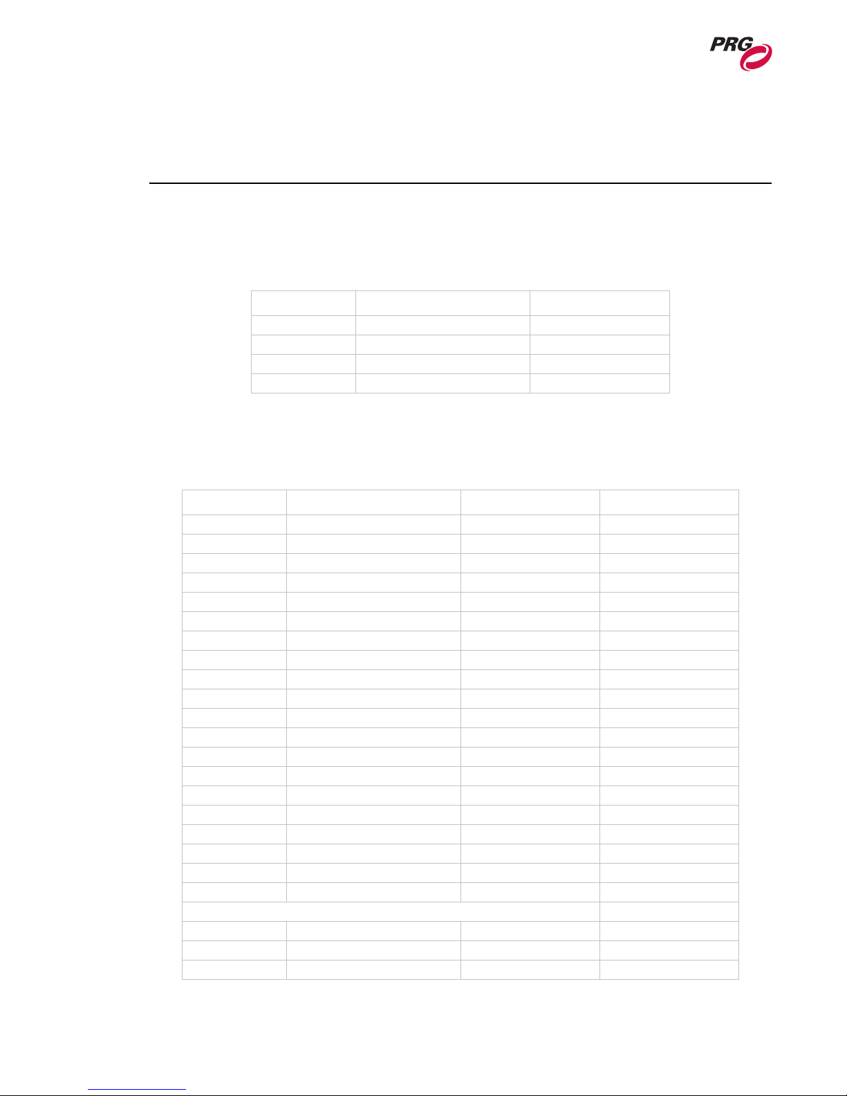
MBOX EXTREME™ MEDIA SERVER USER MANUAL
Virtuoso® Console
Virtuoso Profiles and Channel Map
Table B-1: Virtuoso Light Channel Map
Channel Function Default
1 Intensity 0
2 Red 255
3 Green 255
4 Blue 255
Table B-2: Virtuoso Camera Channel Map
Channel Function Default Virtuoso Control
1 Intensity 255 Intensity
2 Red 255 Color3
3 Green 255 Color2
4 Blue 255 Color1
5-6 Orbit X 32767 Pan
7-8 Orbit Y 32767 Tilt
9-10 Dolly 32767 Beam
11-12 Roll 32767 Edge
13 Spin 127 Zoom
14-15 Field Of View 32767 Shutter
16-17 Pitch 32767 Prism
18-19 Yaw 32767 Prism Index
20 Effect1 0 Rotating Gobo
21 Effect Control 1a 0 Gobo Index
22 Effect Control 1b 0 Shift-Gobo Index
23 Effect 2 0 Effects Wheel
24 Effect Control 2a 0 Effects Index
25 Effect Control 2b 0 Shift-Effects Index
26 Control 0 Misc1
Control
0-9 none
10-19 Version HUD
20-29 Performance HUD
68 02.9800.0001
Page 77
REFERENCE CHARTS : VIRTUOSO® CONSOLE
Table B-2: Virtuoso Camera Channel Map (Continued)
Channel Function Default Virtuoso Control
30-39 FPS Display
40-49 Lights/Camera/Shutter/Key-
stone HUD
50-59 Objects HUD
200 DEBUG ONLY: Trace Dump
240 Rescan Media Library
241 Enable SDI output controls
250 Quit Application
251 Shutdown Computer
252 Restart Computer
253 Restart Application
Table B-3: Virtuoso Shutter Channel Mapping
B
Channel Function Default Virtuoso Control
1 Shape 255 Intensity
2 Shutter X 32767 Pan
3 Shutter X
4 Shutter Y 32767 Tilt
5 Shutter Y
6 Red 0 Color3
7 Green 0 Color2
8Blue 0Color1
9 Shutter Scale 32767 Zoom
10 Shutter Scale
11 Shutter Edge 0 Edge
12 Shutter 1a 0 Framing
13 Shutter 1b 0 Framing
14 Shutter 2a 0 Framing
15 Shutter 2b 0 Framing
16 Shutter 3a 0 Framing
17 Shutter 3b 0 Framing
18 Shutter 4a 0 Framing
19 Shutter 4b 0 Framing
20 Shutter Rotation 127 Framing
02.9800.0001 69
Page 78
MBOX EXTREME™ MEDIA SERVER USER MANUAL
Table B-4: Virtuoso Keystone Channel Mapping
Channel Function Default Virtuoso Control
1 Enable 255 Intensity
2 Keystone X 32767 Pan
3 Keystone X
4 Keystone Y 32767 Tilt
5 Keystone Y
6 Tile Mode 0 Rotating Gobo
7 Tile Overlap 0 Gobo Index
8 Scale 65536 Zoom
9Scale
10 Edge1 0 Prism Index
11 Edge2 0 Edge
12 Edge3 0 Prism
13 Edge4 0 Beam
14 Corner 1 - X 0 Framing
15 Corner 1 - Y 0 Framing
16 Corner 2- X 0 Framing
17 Corner 2- Y 0 Framing
18 Corner 3- X 0 Framing
19 Corner 3- Y 0 Framing
20 Corner 4- X 0 Framing
21 Corner 4- Y 0 Framing
22 Keystone Rotation 127 Framing
Channel Function Default Virtuoso Control
1 Transparency 0 Intensity
2 X Position 32767 Pan
3 X Position
4 Y Position 32767 Tilt
5 Y Position
6 Red 255 Color3
7 Green 255 Color2
8 Blue 255 Color1
9 Z Position 32767 Frost
10 Z Position
11 Scale 32767 Zoom
12 Scale
13 Library 0 Shift-Gobo Wheel
70 02.9800.0001
Table B-5: Virtuoso Object 2D Channel Mapping
Page 79

REFERENCE CHARTS : VIRTUOSO® CONSOLE
Table B-5: Virtuoso Object 2D Channel Mapping (Continued)
Channel Function Default Virtuoso Control
14 Texture 0 Gobo Wheel
15 Play Mode 0 Shift-Edge
16 Play Speed 127 Edge
17 In Frame 0 Prism
18 In Frame
19 Out Frame 65535 Prism Index
20 Out Frame
21 Aspect 0 Shutter
22 Blending 255 Beam
23 Effect1 0 Rotating Gobo
24 Effect Control 1a 0 Gobo Index
25 Effect Control 1b 0 Shift-Gobo Index
26 Effect 2 0 Effects Wheel
27 Effect Control 2a 0 Effects Index
28 Effect Control 2b 0 Shift-Effects Index
29 XFade Type 0 Misc1
30 XFade Timing 0 Gobo Wheel Timing
Play Modes
0-9 forward loop
10-19 reverse loop
20-29 forward once
30-39 reverse once
40-49 forward bounce
50-59 reverse bounce
60-69 random
70-79 forward once - restart on in
frame change
80-89 scrub - in frame
90-99 scrub - out frame
B
Channel Function Default Virtuoso Control
1 Trasparency 0 Intensity
2 Shape Library 0 Shift-Gobo Wheel
3 Shape 0 Gobo Wheel
4 Shape XFade Timing 0 Gobo Wheel Timing
5 Anim Speed 127 Rotating Gobo
6 X Scale 32767 Color1
7X Scale
02.9800.0001 71
Table B-6: Virtuoso Object DMX Mapping
Page 80

MBOX EXTREME™ MEDIA SERVER USER MANUAL
Table B-6: Virtuoso Object DMX Mapping (Continued)
Channel Function Default Virtuoso Control
8 Y Scale 32767 Color2
9Y Scale
10 Z Scale 32767 Color3
11 Z S c a le
12 X Rotation 32767 Beam
13 X Rotation
14 Y Rotation 32767 Edge
15 Y Rotation
16 Z Rotation 32767 Zoom
17 Z Rotation
18 X Spin 127 Shutter
19 Y Spin 127 Prism
20 Z Spin 127 Prism Index
21 Effect 1 0 Effects Wheel
22 Effect Control 1a 0 Effects Index
23 Effect Control 1b 0 Shift-Effects Index
Table B-7: Virtuoso Mbox Extreme Starting Address
Function DMX Address
Light - Ambient 1
Light - Spot 1 5
Light - Spot 2 9
Light - Spot 3 13
Light - Spot 4 17
Camera 21
Shutter 47
Keystone 67
Object 1 89
Object 2 142
Object 3 195
Object 4 248
Object 5 301
72 02.9800.0001
Page 81

Miscellaneous
Effects and Transitions
The following tables provide a complete list of effects and transitions. Where applicable, the userconfigurable parameters are defined.
Texture Effects
Value Effect Description Control 1 Control 2
0 None No effect
1 Monochrome convert colors to grayscale amount
2 Sepia Tone convert colors to sepia tone image amount
3 Invert color invert
4 Color Reduce reduce color space amount
5 Bright/Contrast brightness and contrast controls brightness contrast
6 Saturation saturation control saturation
7 Hue hue adjustment hue
8 Gamma gamma adjustment gamma
9 Exposure exposure adjustment exposure
10 Solarize solarize effect amount
11 Black & White convert image to black and white threshold
12 Black Alpha dark areas transparent threshold
13 X-Ray inverted grayscale amount
14 Bloom soften edges, add glow radius intensity
15 Gloom dulls highlights radius intensity
16 Sharpen increases image detail by sharpening sharpness
17 Median reduce noise with median calculation
18 Color Switch RGB -> RBG/BGR/GBR/GRB mode intensity
19 Varietal Lines spread single row over vertical space row
20 Color Shift dynamic color shift (sine function) range speed
21 Blur simple/quick image blur amount
22 Gaussian Blur more sophisticated / slow blur amount
23 Circular Screen circular shaped halftone screen width sharpness
24 Dot Screen dot patterned halftone screen width angle
25 Line Screen line patterned halftone screen width angle
26 Hatched Screen hatched patterned halftone screen width angle
27 CMYK Screen color, halftoned screen width angle
28 Tiles image tiling divisions
29 Circular Crop circular image crop with edge blur size edge
REFERENCE CHARTS : MISCELLANEOUS
Table B-8: Texture Effects
B
02.9800.0001 73
Page 82

MBOX EXTREME™ MEDIA SERVER USER MANUAL
Value Effect Description Control 1 Control 2
30 Rectangular Crop rectangular image crop with edge blur size edge
31 Mirrors various mirror modes mode
32 Horizontal Bars break image into bars number width
33 Vertical Bars break image into bars number width
34 Double Vision offset image and overlay x offset y offset
38 Flicker dynamic flickering effect size speed
39 Shake dynamic shaking effect size speed
40 Wobble dynamic wobbling effect size speed
41 Bump Distortion bump distortion radius scale
42 Hole Hole distortion radius
43 Pinch pinch distortion radius scale
44 Torus torus distortion width
45 Twirl twirl distortion radius scale
46 Vortex vortex distortion radius angle
47 Lozenge lozenge distortion width
48 Edge Work Black & White conversion radius
49 Edge Detect edge detection with color intensity
50 Crystallize break up into crystal pattern radius
51 Pixelate pixelate image scale
52 Pointillize break image into points radius
53 Kaleidoscope geometric distortion angle
54 LED Wall break up into dots dot amount dot size
55 Cartoon cartoon effect line width color reduction
56 White Alpha white areas transparent threshold
57 Red Alpha red areas transparent threshold
58 Green Alpha green areas transparent threshold
59 Blue Alpha blue areas transparent threshold
60 White Only everything but white areas transparent threshold
61 Red Only everything but red areas transparent threshold
62 Green Only everything but green areas transparent threshold
63 Blue Only everything but blue areas transparent threshold
Table B-8: Texture Effects
74 02.9800.0001
Page 83

Transitions
Value Transition Description
0 Dissolve dissolve
1 Dissolve2 dissolve
2 Wipe Right slightly blended right to left wipe
3 Wipe Down slightly blended top to bottom wipe
4 Wipe Diagonal slightly blended diagonal wipe
5 Wash Right more blended right to left
6 Wash Down more blended top to bottom
7 Wash Diagonal more blended diagonal
8 White Right blended white stripe left to right
9 White Down blended white stripe top to bottom
10 White Diagonal blended white stripe diagonal
11 Through Black fade to black and back in
12 Through White fade to white and back in
13 Through Red fade to red and back in
14 Bright First transition by brightness of new image
15 Dark First transition by darkness of new image
16 Dots fade with small dots
17 Big Dots fade with big dots
18 Burst white star burst transition
19 Flash white flash transition
20 Slow Dissolve dissolve that comes in more slowly
21 Slower Dissolve dissolve that comes in even more slowly
22 Rotate Left simple 3D rotate effect
23 Rotate Right simple 3D rotate effect
24 Rotate Up simple 3D rotate effect
25 Rotate Down simple 3D rotate effect
26 Rotate Center Vertical simple 3D rotate effect
27 Rotate Center Horizontal simple 3D rotate effect
28 Zoom Out zoom out and back in
29 Zoom In zoom in and back out
30 Horizontal Bars 10 horizontal bars, hard edge
31 Horizontal Bars + Blend 10 horizontal bars, blended edge
32 Vertical Bars 10 vertical bars, hard edge
33 Vertical Bars + Blend 10 vertical bard, blended edge
34 Circle Center circle out from center
35 Circle Center + Blend circle out from center, blended edge
36 Concentric Circles circles out from center, blended edges
37 Push Right new image pushes in left to right
REFERENCE CHARTS : MISCELLANEOUS
Table B-9: Transitions
B
02.9800.0001 75
Page 84

MBOX EXTREME™ MEDIA SERVER USER MANUAL
Value Transition Description
38 Push Left new image pushes in right to left
39 Push Down new image pushes in top to bottom
40 Push Up new image pushes in bottom to top
255 Object Fade fade out on current object, fade in on new object
Table B-9: Transitions
76 02.9800.0001
 Loading...