

Preway BI28B, BI36B, BI42B Installation, Service Instructions & Parts
INSTALLATION, SERVICE INSTRUCTIONS
AND PARTS LIST
FOR
BUILT-IN FIREPLACE
WITH
Prefabricated Chimney
MODELS
MODEL NO.
SIZE
Bl28B
TYPE E
TYPE E
28”-Zero Clearance
36” - Zero Clearance
42” - Zero Clearance
DO NOT INSTALL IN MOBILE HOME
THIS MANUAL WILL HELP YOU TO OBTAIN EFFICIENT, DEPENDABLE SERVICE
FROM THE FIREPLACE AND CHIMNEY. AND ENABLE YOU TO ORDER REPAIR
PARTS CORRECTLY. KEEP IN A SAFE’PLACE FOR FUTURE REFERENCE.
WHEN WRITING, ALWAYS GIVE THE FULL MODEL NUMBER WHICH IS ON THE
FRONT OF THE RIGHT PORCELAIN FIREBOX SHIELD.
DO NOT MODIFY OR ALTER THE CONSTRUCTION OF THIS FIREPLACE OR
COMPONENTS. ANY MODIFICATION OR ALTERATION OF CONSTRUCTION
VOIDS THE WARRANTY AND APPROVALS OF THIS UNIT.
Manufactured by
PREWAY INC.
General Offices and Factory
WISCONSIN RAPIDS, WISCONSIN 54494

general
Remove
811
parts and check to be
sure
they are
there. Report to your dealer if any parts
are
missing
or
damaged.
One Carton Containing
Fireplace and Spark Strips.
ALSO
Any other cartons you have ordered to complete
your chimney installation.
NOTE: Ta identify pieces, refer to Parts Illustration.
Local Codes
Local
building codes should be consulted in all cases
as to the particular requirements concerned with the
installation of factory built fireplaces,
DO NOT INSTALL IN MOBILE HOME
IMPORTANT
The fireplace may be installed either with the
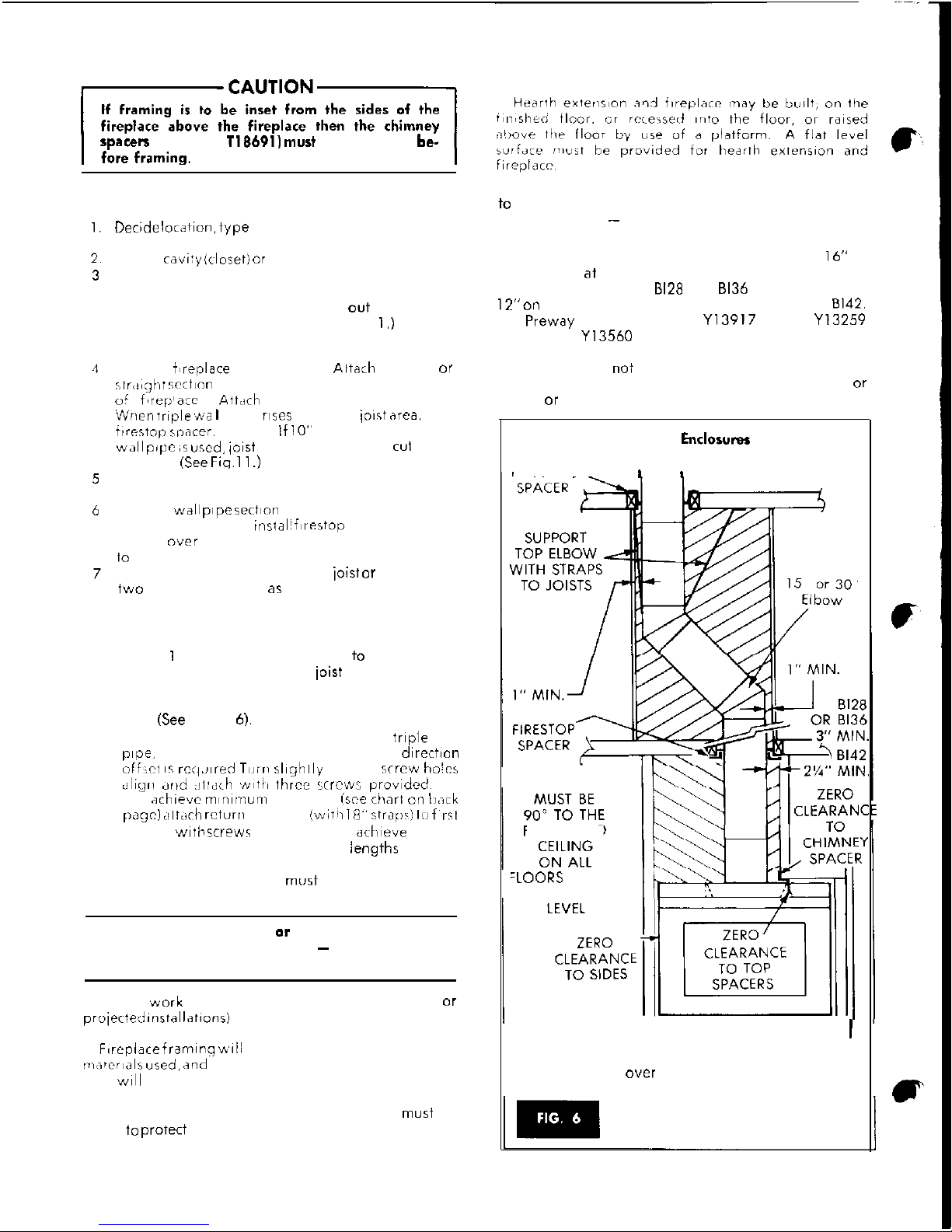
area above the fireplace open within the enclosed framing (chase framing) or inset from the
sides of the fireplace. When insetting is desired
the chimney spacer MUST be installed (See Fig. 6).
For your safety and protection, fireplace and
chimney should be grounded. Use Ground Rod,
clamp and wire to ground chimney and fireplace.
MUST
TERMINA
36” MINIMUM
ABOVE ROOF
FIREPLACE
OPENIN<
FLOOR
‘-‘-PLACE ‘METAL
HEARTH EXTENSION
STRIPS UNDER
DIMENSIONS
FIREPLACE AND
HEARTH EXTENSION
NOTE:
“J”
Clearance may be 12” Minimum
with
Preway
Insulated Wall Shield or Equivalent.
bottom, sides, and back of the unit. Chimney sections
above the
i&t
area require a minimum clearance of
one inch to combustible materials. Chimney
sections
from the top of the fireplace to the first joist are re-
quired a minimum
cie~rance
of 3 inches.
Firestop
spacers must be installed at every ceiling level
which
will automaticIly provide
the
necessary
clearance to
the joist.
Any fireplace must not be installed closer than
specified in Chart 2 (Page 3) to any unprotected
corn-
bustible
wall, perpendicular to the fireplace openings
(See Fio. 1)
unless a
Prewav
wall shield, Model WS40
or
CLEARANCES:
S,des ~
0”
Back ~~ 0”
Base ~
0”
TO TOP OF
FIREPLACE,
WIRING ACCESS
PLATE AND
78”
See
Chart
1
ELECTRIC INLET
CHART 1
Dimensions
28”,
36”. 42” Fireplace
Bl28B
81368
81426
A 22”
30”
36”
To Top of Fireplace
I
38’8”
I
40’%”
18”
20”
I
Opcnsng
I
I
J
36”
36”
36-
Clearances
!
When installed in accordance with these instructions,
the basic unit may touch combustible materials at the
NOTE: This fireplace is NOT intended as a furnace to
heat an entire home. Use for supplementary heating
only.
2

location
INSTALLATlON
The overall height from bottom of fireplace
to
chimney flue outlet is to he
not
less than 16 for
Models
81288, 81366
or 12’6” for the
81428
with the
standard chimney termination.
(ERTSA
or IORTSA). If
Decorative Chimney
(DCT)
is used overall height may
be reduced on
81288
and
81368 lo
12’6”.
81288
and
81368
overall height may be reduced to 11’ by using
a
BFSL
Thimble in place of a fIrestop spacer at first
ioist area. Installation may be 90 feet in height but
must be supported at every 35 foot level.
Fireplace lwdlion will he influenced by such factors
as traffic in rooms, doors
and
windows and
construe-
tion
above and below the
firepldce.
~irepl~e may be installed in any location which will
provide the necessary clearances. A location that r”-
yuires
cutting the least number of ioists or rafters
WIII
simplify and reduce installation cost. The fireplace
may be installed
directly
on the floor or elevated on
a
wooden or masonry l,Iatform if desired. However. the
floor or platform must be solid and continuous to
prevent any air from entering the room from under
the fireplace. See Page 5 for chase construction.
The fireplace may be positioned and then the framing built around it or the framing may be constructed
and the fireplace pushed into the opening. (See
Fig. 10.) The dimensions shown on Pages 2 and 3
may
be used to
construci
the fireplace opening.
CORNER INSTALLATION
This can be the most economical in
rooms
where
wall space is at a premium. Because of the slanted
sides, the fireplace seems to take less area of floor
space than being
proiected
into the
room
from a flat
wall. (See Fig.
5.)
Cross Section
TRIPLE WALL
INSULATION
DAMPER
~~L”L
~T~;l;l”
HANDLE
\
FRAME ‘BOTTOM
INSULATION
ASSEMBLY
PROJECTION
PROJECTION
.
CLEARANCE TO CORNER MUST BE 36”.
”
IF
WS40 WALL SHIELD IS INSTALLED
*
CAN BE REDUCED TO 12”
Framing Dimensions
CHART 2
Dimensions
28”.
36” 42” Fireplace
Measurement
1
B12BB
1
81368
1
81428
I
A
1
14%” SQ.114%” SQ.
1
16%” SQ.
B
I
7%”
I
7w
I 8%”
H
2%”
2%”
13/4”
J
38”
46”
52”
Y
1 0” 71”
7K*
t
I.
1
,
I
__
I
-_
L
/
49%” 1 55%” 1 59%”
With 8FSL
Firestop
Spacer
at First Joist Area
A
17%” SQ.
17%” SQ.
6
8A”
87@”
H
1
‘/s”
1
vi’
HEARTH
EXTENSION
42”~
16”
52”~
1
6”
66”XzO”
NOTE: Los Angeles code requires Hearth to be
12”
each side of Fireplace
openirng
and 20” deep.
3
installation
spacers
(Part No. T18691)
must
be attached
be-
Installation
decide location,
type
of installation, etc. and lay““, on floor.
Frame
cavi!),
(closet) or opening for fireplace.
Prepare floor by installing hearth extension and
platform, if desired. Place metal strips (provided)
under fireplace and extending out to where it
will be under hearth also. (See Fig.
I.)
This will
prevent any sparks from reaching the floor.
Place
iNreplace
in position. Attach elbow or
rIr,agt~~t scct~on
of triple wall pipe in place on top
oi
f’rep’arc
Atta:h
with 3 screws provided.
Wnen triple ‘wa
I
pipe
ruses
through
ioist area.
use
i~restnp
s~nacer.
NOTE: If
IO”
diameter triple
wall pope ,s
used,
ioist
will have to be
cuI
and
boxed. (See
Fit. 11.1
Frame around fireplace sides and up to ceiling
add sections of pipe as you frame.
If triple wall
p,pe
sect,“,, goes through framed
opening in ceiling,
instali fIrestop
spacer by sliding up over triple wall pipe section and nailing
to
bottom side of joists.
If an offset is needed to miss a
joist or
beam, use
two elbows and pipe as needed. See instructions
below.
To Install Elbows
Maintain I inch minimum clearance to combustibles
for sections located above the
joist
area where the
fireplace is located. Maintain 3 inch clearance to
combustibles for sections located directly above the
fireplace (See Figure
6).
1.
Place elbow (without straps) on vertical
triple
wall
pope.
(or an fireplace), pointed in the directfon
r:,fF,ct 1s
rci,.,,rrd Turn shghlly
until s<rcw holes
tiligrl drid ;~llci~h \Nlttl
tt,rce
~crcws provided~
2. To .ichievc
minimum
offset,
(ice chart on b;lrk
page) cilt,ict, return
elbow
(.*iti~ lij” srrfii)ij II) f~rsl
elbow
wit/?
screws provided. To
a&eve
further
offset, you may install various
iengths
of triple
wall pipe between the elbows to a maximum
length of 15 feet. (This
must
be supported with
straps every 6 feet.) (See Back Page.)
IMPORTANT: If gas line or outside combustion
air is to be built in to fireplace - install it before
framing in fireplace.
Frame ,w”rk around the fireplace (either in flush or
project% installatfons)
can be planned to incorporate,
book shelves. wood bins, closets, etc.
F,replace
framing w,ll
be governed by the face
~mater,als
used,
<and
how far above and-to each side
they
WIII
extend.
When the fireplace is installed on a combustible
floor, a non-combustible hearth extension
mus+
be
used +” prorect the floor in front of the opening. (See
Chart on Page 2 for proper dimensions.)
The fireplace may be placed on a platform in order
to
apply the face material completely around the opening. CAUTION - Do not block off air opening at
bottom of fireplace.
The Hearth Extension must extend at least 16” in
front of and at least 8” beyond each side of the fireplace opening for the 8128 and 6136 and 20” in front,
12” on
each side of the fireplace opening for the 8142.
Use Preway Hearth Extension
Yl3917
for 28”.
Y13259
for 36” and
Yl3560
for the 42” fireplace. The Hearth
Extension may be covered with non-combustible materials which do not ignite and burn. These are steel,
iron, brick, tile, concrete, slate, asbestos, glass or
plaster or any combination
Chimney
Enclorures
‘IRESTOP-
I
I
ENCLOSURES
FLOOR AND
‘LOORS
ABOVE
FIRST JOIST
CHASE FRAMING
INSET FRAMING
1
NOTE:
Use only four elbows per installation and
never over 30” maximum. Elbow may
be used directly on fireplace.
4
installation
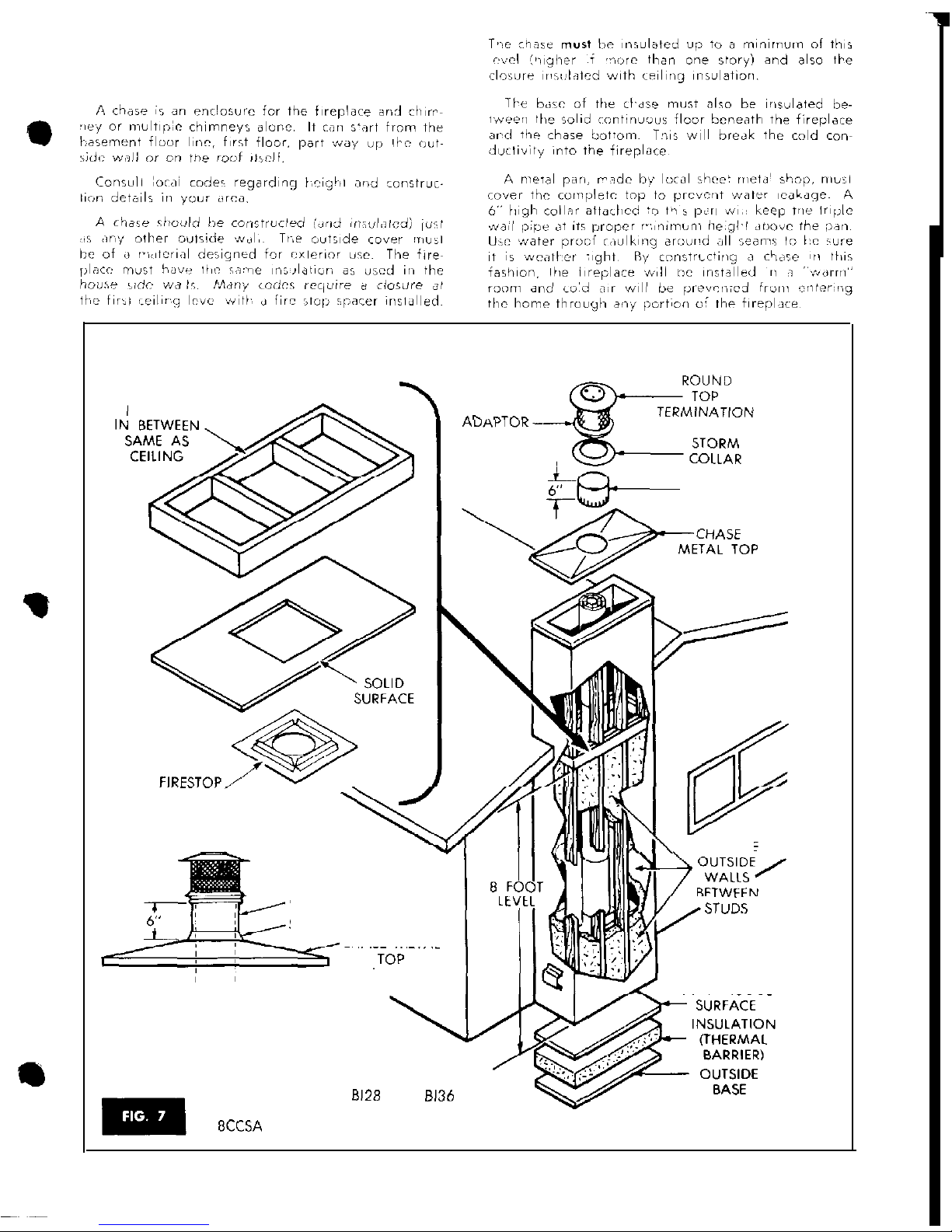
Chimney Chases
STUD
(JOISTS)
INSULATE
” ?.
. __^^
FbF
CHASE COLLAR
SPACER
CHASE COLLAR
STORM COLLAR
CHASE METAL
1 b,
-INSULATE
STUb.5
SOLID
CONTINUOUS
REFER TO PAGE 3 FOR MINIMUM
OVERALL HEIGHT OF FIREPLACE
TO FLUE OUTLET.
8128
AND
6136
MAY USE BCC CHASE CAP WITH
8CCSA
SPARK ARRESTOR.
5
 Loading...