

Page 1

COACH MANUFACTURER
MAINTENANCE MANUAL
H3-41, H3-45, VIP
PA1561
March 2009
Page 2

PA1561
March 2009
Beginning with vehicle: A-1470
Featuring:
y New headlights and bumper design
Page 3

SECTION 00: GENERAL INFORMATION
TABLE OF CONTENTS
1. FOREWORD........................................................................................................................................... 2
2. SCHEMATICS........................................................................................................................................ 2
3. PRECAUTIONS TO BE OBSERVED BEFORE WELDING.................................................................. 2
4. SAFETY NOTICE................................................................................................................................... 4
4.1 DATA PLATES AND CERTIFICATIONS......................................................................................... 4
4.1.1 Engine ...................................................................................................................................... 4
4.1.2 Transmission............................................................................................................................ 4
4.1.3 Drive Axle................................................................................................................................. 5
4.1.4 Front Axle................................................................................................................................. 5
4.1.5 Power Steering Pump .............................................................................................................. 5
4.1.6 Coach Final Record.................................................................................................................. 6
4.1.7 Safety Certification................................................................................................................... 6
4.1.8 DOT Certification Label............................................................................................................6
4.1.9 Fuel Tank Label........................................................................................................................ 6
4.1.10 EPA Engine Label .................................................................................................................... 6
4.1.11 Vehicle Identification Number (VIN)......................................................................................... 6
5. FASTENER STRENGTH IDENTIFICATION.......................................................................................... 8
5.1 SELF-LOCKING FASTENERS........................................................................................................ 9
5.2 RECOMMENDATIONS FOR REUSE ............................................................................................. 9
5.3 SIX LOBED SOCKET HEAD ........................................................................................................... 9
ILLUSTRATIONS
FIGURE 1 : DETROIT DIESEL SERIES 60............................................................................................................... 4
FIGURE 2: VOLVO D13 ENGINE DATA PLATE........................................................................................................ 4
FIGURE 3: WORLD TRANSMISSION...................................................................................................................... 5
FIGURE 4: ZF-ASTRONIC TRANSMISSION............................................................................................................. 5
FIGURE 5: TYPICAL SERIAL & MODEL NUMBER..................................................................................................... 5
FIGURE 6 : TYPICAL SERIAL AND MODEL NUMBERS .............................................................................................. 5
FIGURE 7: ISS TYPICAL SERIAL & MODEL NUMBERS ............................................................................................. 5
FIGURE 8 : POWER STEERING PUMP SERIAL NUMBER .......................................................................................... 5
FIGURE 9: POWER STEERING PUMP.................................................................................................................... 5
FIGURE 10: DOT CERTIFICATION PLATE .............................................................................................................. 6
FIGURE 11: ENGINE COMPARTMENT................................................................................................................... 6
FIGURE 12 : VEHICLE I.D.................................................................................................................................... 6
FIGURE 13 : VEHICLE IDENTIFICATION NUMBER................................................................................................... 7
FIGURE 14 : THREAD NOTATION......................................................................................................................... 8
FIGURE 15: BOLT STRENGTH MARKINGS............................................................................................................. 8
FIGURE 16 : SELF-LOCKING FASTENERS............................................................................................................. 9
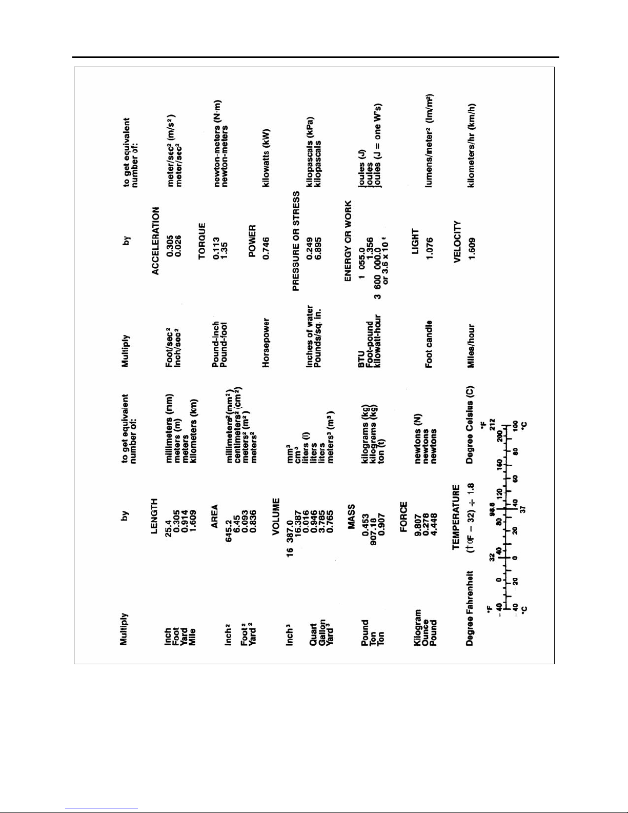
FIGURE 17: METRIC - US STANDARD CONVERSION TABLE................................................................................... 10
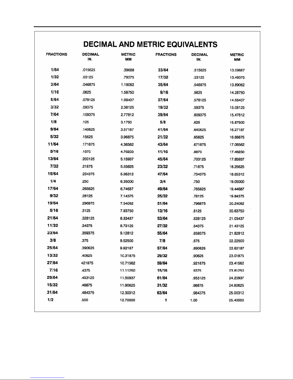
FIGURE 18: CONVERSION CHAR........................................................................................................................ 11
PA1561 1
Page 4
Section 00 : GENERAL INFORMATION
1. FOREWORD
This manual includes procedures for diagnosis,
service, maintenance and repair for components
of the H3 series coaches or VIP model listed on
the front cover page.
This manual should be kept in a handy place for
ready reference by the technician. If properly
used, it will meet the needs of the technician and
owner.
Information provided in Section 1 through 24
pertains to standard equipment items, systems
and components as well as the most commonly
used optional equipment and special equipment
offered on the coach models covered by this
manual.
At the beginning of each section; a Table of
Contents and a list of illustrations give the page
number on which each subject begins and where
each figure is located.
Coach operating information is provided in a
separate Operator's Manual. Audio/Video
system operator instructions are also included in
a separate manual.
More specific information on engine and
transmission operating, maintenance, and
overhaul information is contained in the
applicable engine or transmission service
manual published by the engine or transmission
manufacturer. Engine and transmission parts
information is contained in the applicable engine
or transmission parts catalog published by the
engine or transmission manufacturer.
All information, illustrations and specifications
contained in this manual are based on the latest
product information available at the time of
publication approval. The right is reserved to
make product changes at any time without
notice.
Note: Typical illustrations may be used;
therefore minor illustration difference may exist
when compared to actual parts or other
publications.
Prevost Car occasionally sends Maintenance
Information, Warranty Bulletins, Safety Recalls
or other literature to update users with the latest
service procedures. They are issued, when
required, to supplement or supersede
information in this manual. Update sheet should
be filled out and bulletins should be filed at the
end of their respective section for future
reference.
2. SCHEMATICS
Vehicle AIR SCHEMATICS and ELECTRICAL
SCHEMATICS are provided in the technical
publications box. Refer to those schematics for
detailed circuit information or during diagnosis.
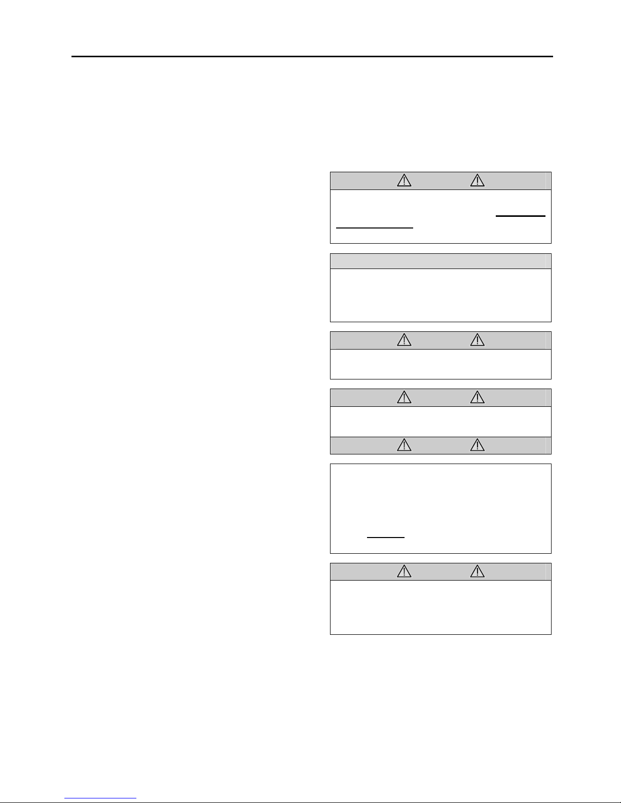
3. PRECAUTIONS TO BE OBSERVED
BEFORE WELDING
CAUTION
Precautions are to be observed before
welding to minimize the risk of major and
costly damage caused to the vehicle
electronic components.
NOTE
Execute procedure no: SAV060034
"MULTIPLEX MODULES DISCONNECTION
PROCEDURE PRIOR TO WELDING"
included at the end of this section.
CAUTION
For vehicles equipped with a WCL system,
disconnect electronic controller connector.
CAUTION
Cover electronic control components and
wiring to protect from hot sparks, etc.
CAUTION
Position welding machine ground clamp as
close as possible to the work. Ensure that
the welding machine ground return clamp
is well secured and makes a good
electrical contact with a large metallic area
of the chassis located as close as possible
to the welding point.
CAUTION
Do not use TIG welding process on the
vehicle. This high frequency current
process can seriously damage the
electronic components.
PA1561 2
Page 5
Section 00 : GENERAL INFORMATION
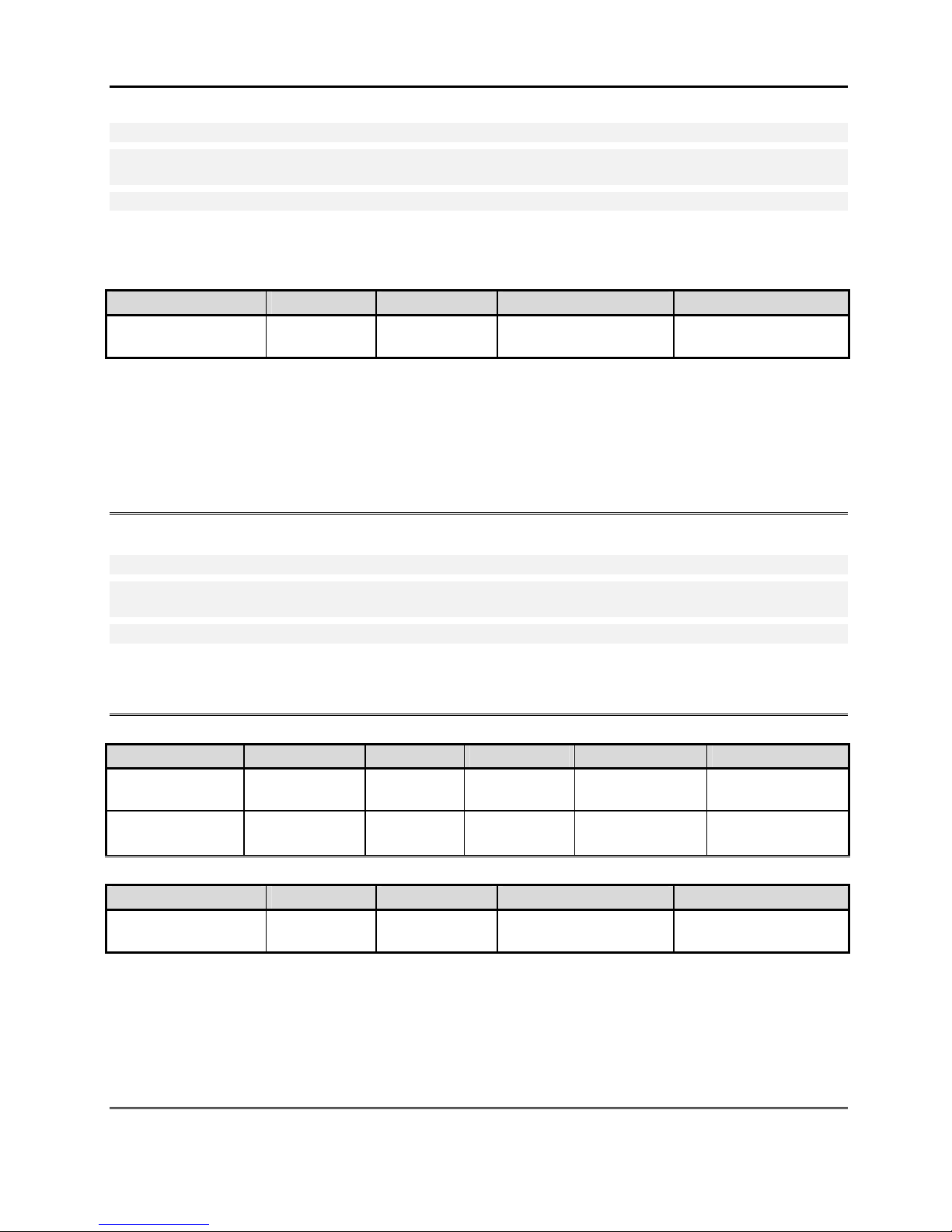
STEEL – STEEL WELDING
Caution: Before welding, disconnect electronic modules and battery terminals.
Warning: Welding surfaces must be free of scale, slag, rust, paint, grease, humidity or other foreign material
that would render welding impossible.
Warning: Only a qualified and experienced person must do welding.
• FCAW (Flux Cored Arc Welding) process ;
• Electrode wire conforms to A5.20 AWS (American Welding Society) specifications ;
• E4801T-9-CH, type electrode wire with 0,045“ diameter (1,14 mm) ;
Material Thickness Voltage Current Wire Feed Rate Shielding Gas
1/8” to ½” 26 ± 2 volts 260 Amps 450 ipm. approx.
If necessary and with great care to prevent perforating the material, it is possible to use a conventional
electric arc welding machine according to the following specifications:
• SMAW (Shielded Metal-Arc Welding) process ;
• Welding rod conforms to A5.1 of AWS (American Welding Society) specifications; E 7018 type welding
rod with 1/8” diameter (3,2 mm).
• Current: 100 amperes to 150 amperes; optimum at 120 amps.
It is important to grind weld bead starts and stops and also to grind arc strikes from surfaces.
75% argon – 25% CO2
or 100% CO2
STEEL - STAINLESS STEEL OR STAINLESS STEEL - STAINLESS STEEL WELDING
Caution: Before welding, disconnect electronic modules and battery terminals.
Warning: Welding surfaces must be free of scale, slag, rust, paint, grease, humidity or other foreign material
that would render welding impossible.
Warning: Only a qualified and experienced person must do welding.
• GMAW (Gas Metal-Arc Welding) process;
• Welding wire conforms to AWS (American Welding Standards) A5.9 specifications;
• 308LSi type welding wire with 0.035" diameter (0,9 mm);
STEEL - STAINLESS STEEL WELDING
Steel Thickness SS Thickness Voltage Current Wire Feed Rate Shielding Gas
Less than 1/8” Any type 20±1.5 volts 130±15 Amps 290 ipm approx.
1/8” and more Any type 22±1.5 volts 160±15 Amps 330 ipm approx.
STAINLESS STEEL - STAINLESS STEEL WELDING
SS Thickness Voltage Current Wire Feed Rate Shielding Gas
Any type 20 ± 1.5 volts 130 ± 15 Amps 290 ipm approx.
If necessary and with great care to prevent perforating the material, it is possible to use a conventional
electric arc welding machine according to the following specifications:
• SMAW (Shield Metal-Arc Welding) process;
• Welding rod conforms to AWS (American Welding Standards) A5.4 specifications; 308L-17 type welding
rod with 3/32" diameter (2,4 mm);
• Current: - 50 amperes to 90 amperes, optimum at 60 amperes.
It is important to grind weld bead starts and stops and also to grind arc strikes from surfaces.
90% He, 7.5% Ar,
2.5% CO2
90% He, 7.5% Ar,
2.5% CO2
90% He – 7.5% Ar,
2.5% CO2
PA1561 3
Page 6
Section 00 : GENERAL INFORMATION
4. SAFETY NOTICE
This maintenance manual has been prepared in
order to assist skilled mechanics in the efficient
repair and maintenance of PREVOST vehicles.
This manual covers only the procedures as of
manufacturing date.
Safety features may be impaired if other than
genuine PREVOST parts are installed.
Torque wrench tightening specifications must be
strictly observed. Locking devices must be
installed or replaced by new ones, where
specified. If the efficiency of a locking device is
impaired, it must be replaced.
This manual emphasizes particular information
outlined by the wording and symbols:
Warning: Identifies an instruction which, if not
followed, could cause personal injuries.
Caution: Outlined an instruction which, if not
followed, could severely damage vehicle
components.
Note: Indicates supplementary information
needed to fully complete an instruction.
Although, the mere reading of such information
does not eliminate the hazard, understanding of
the information will promote its correct use.
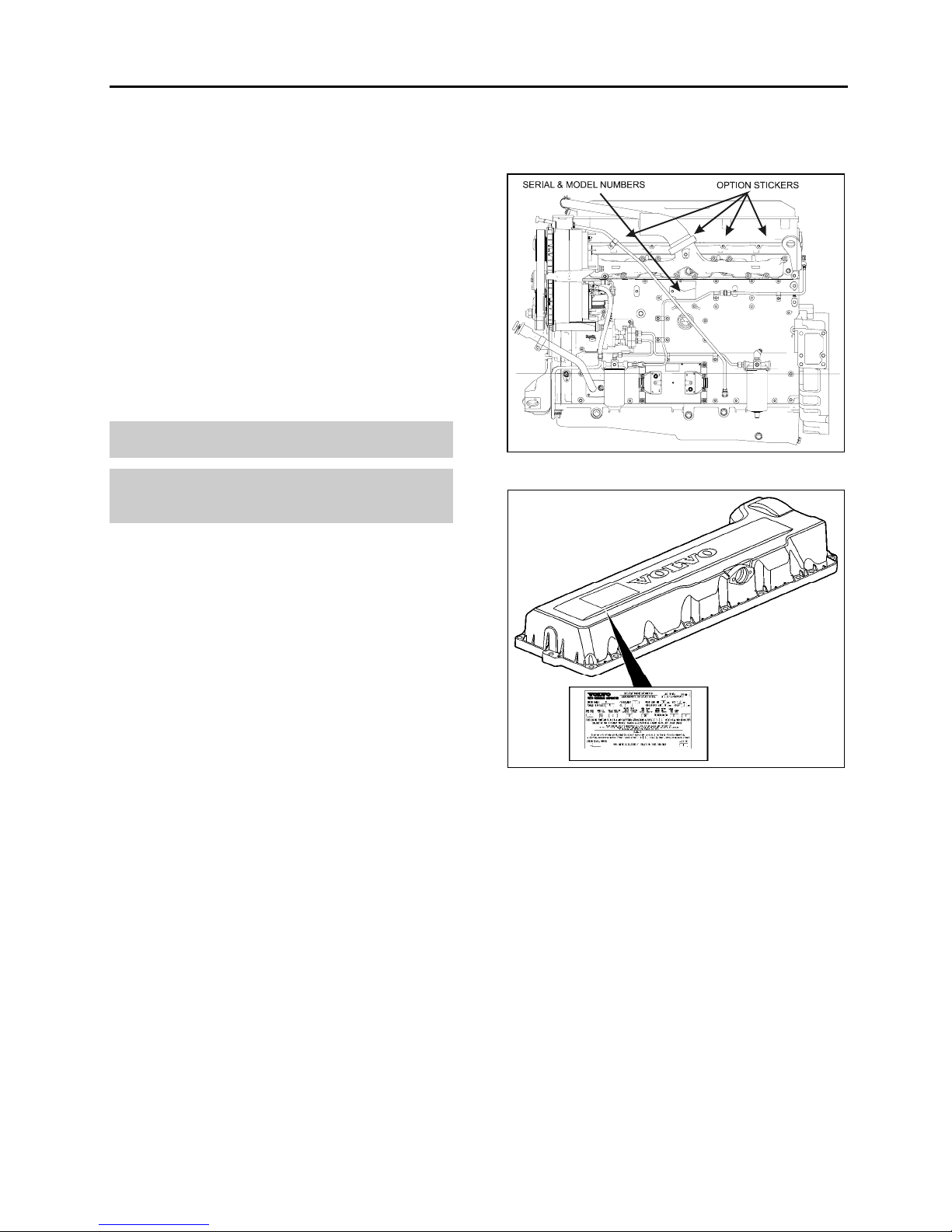
Volvo D13 Engine
Volvo D13 engine serial and model numbers are
stamped on the cylinder head (Fig. 2).
FIGURE 1 : DETROIT DIESEL SERIES 60 00043
4.1 DATA PLATES AND CERTIFICATIONS
Delay and confusion can be avoided by placing
the complete vehicle identification number of the
coach and the serial numbers of the engine on
parts orders and correspondence. Also, the
transmission, axles, power steering pump
chassis and other major components are
identified by serial numbers.
4.1.1 Engine
DDC Series 60 Engine
The engine serial and model number are
stamped on the cylinder block (as viewed from
the flywheel end) on the left side just below the
fire deck and above the cast-in Detroit Diesel
logo (Fig. 1).
In addition, option plates made of laminated
paper are located on the rocker cover (starter
side). The engine serial and model number and
a list of the optional engine equipment is written
on the option plate. Refer to this information
when ordering replacement parts (Fig. 1).
FIGURE 2: VOLVO D13 ENGINE DATA PLATE
00052
4.1.2 Transmission
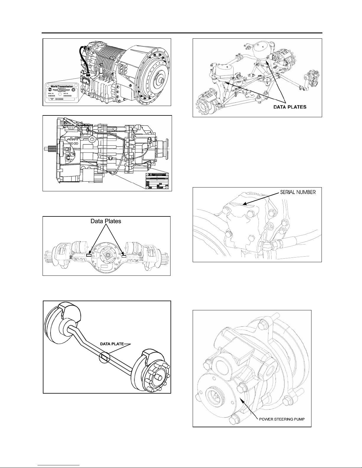
The transmission identification plate is located:
Allison - on the oil level dipstick side.
ZF - on the transmission housing, on the vehicle
R.H. side.
The identification plate shows the transmission
serial number, part number (assembly number),
and model number. Use all three numbers when
ordering parts.
PA1561 4
Page 7
Section 00 : GENERAL INFORMATION
FIGURE 3: WORLD TRANSMISSION 07076
FIGURE 4: ZF-ASTRONIC TRANSMISSION 00040
4.1.3 Drive Axle
FIGURE 5: TYPICAL SERIAL & MODEL NUMBERS 11019
4.1.4 Front Axle
FIGURE 7: ISS TYPICAL SERIAL & MODEL NUMBERS0025
4.1.5 Power Steering Pump
• DDC Series 60 Engine
Power steering pump serial number is engraved
on the pump casing (Fig. 8). The pump is
mounted on the engine beside the crankshaft
pulley.
FIGURE 8 : POWER STEERING PUMP SERIAL NUMBER
00035
• Volvo D13 Engine
Power steering pump is mounted on the engine
and located underneath the air compressor
(Fig.9).
FIGURE 6 : TYPICAL SERIAL AND MODEL NUMBERS
PA1561 5
10024
FIGURE 9: POWER STEERING PUMP
Page 8
Section 00 : GENERAL INFORMATION
4.1.6 Coach Final Record
The Coach Final Record is a record of all data
pertaining to the assembly of the coach. This
record is included in the technical publication
package supplied with the coach. Retain this
record in the company records office for
reference and safe-keeping.
4.1.7 Safety Certification
Coach components meet specifications and
standards as follows:
- Material and parts conform to ASTM and/or
SAE standards in effect at the time of
manufacture.
- All factory-installed interior materials meet
FMVSS 302 for fire resistance.
- Certified according to Provincial, State and
Federal Safety standards (Canadian and US)
BMCSS, FMVSS, and CMVSS.
Other applicable certification labels are affixed to
the component.
4.1.8 DOT Certification Label
This certifies that coaches manufactured by
Prevost Car Inc., comply with all Federal Motor
Vehicle Safety Standards at the time of
manufacture. The DOT Certification label is
affixed on the wall, behind the driver's seat.
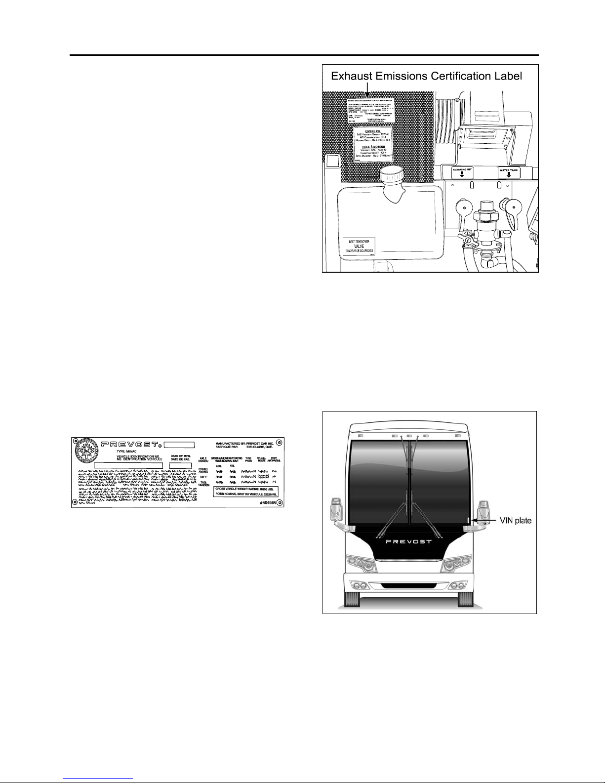
FIGURE 11: ENGINE COMPARTMENT 23229
4.1.11 Vehicle Identification Number (VIN)
The seventeen digit vehicle identification number
(VIN) is located on a plate (Fig. 12) located on
the windshield frame pillar (driver's side). The
VIN is visible from the outside of the coach.
Make sure the correct vehicle identification
number is given when ordering replacement
parts. Using the VIN when ordering parts will
facilitate processing.
FIGURE 10: DOT CERTIFICATION PLATE 00016
4.1.9 Fuel Tank Label
The fuel tank label is molded on the side of the
fuel tank. To read this label, unscrew the fuel
tank access panel nuts located at the left in the
condenser compartment.
4.1.10 EPA Engine Label
The exhaust emission certification label affixed
above the oil reserve tank certifies that the
engine conforms to federal and any state
exhaust emission regulations (Fig. 11). It gives
the operating conditions under which certification
was made.
PA1561 6
FIGURE 12 : VEHICLE I.D. 18680
Note: Record the VIN in the coach
documentation and keep with company records.
The VIN will normally be used for vehicle
registration and for obtaining vehicle insurance
coverage.
Page 9
Section 00 : GENERAL INFORMATION
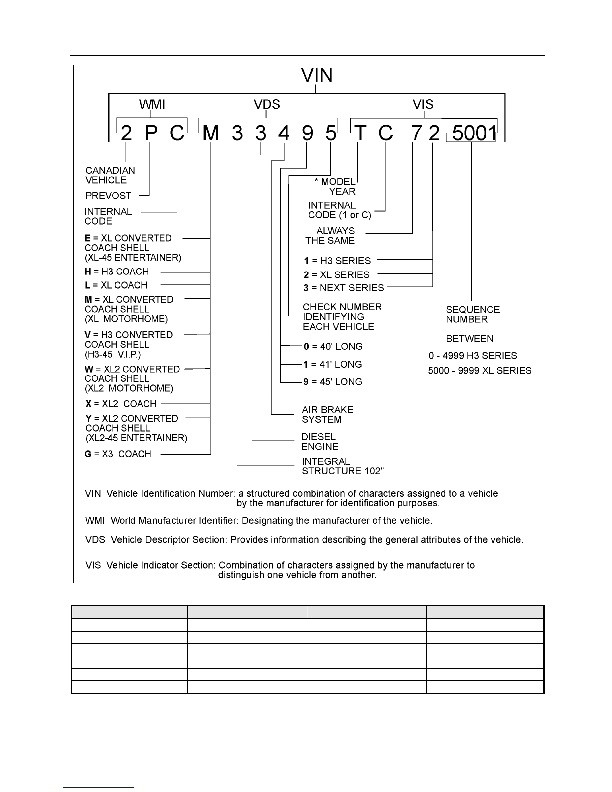
FIGURE 13 : VEHICLE IDENTIFICATION NUMBER 00050
YEAR CODE YEAR CODE
2000 Y 2006 6
2001 1 2007 7
2002 2 2008 8
2003 3 2009 9
2004 4 2010 A
2005 5 2011 B
PA1561 7
Page 10
Section 00 : GENERAL INFORMATION
5. FASTENER STRENGTH IDENTIFICATION
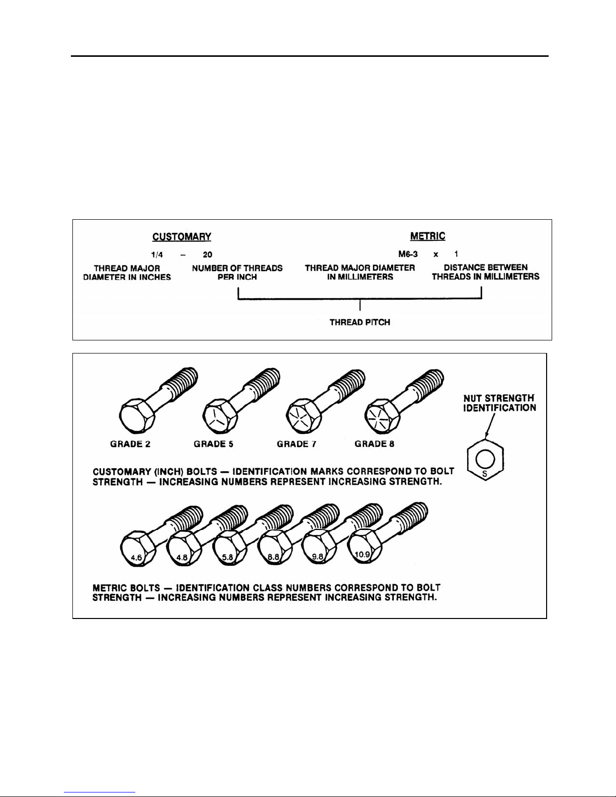
Most commonly used metric fastener strength
property classes are 9.8 and 10.9 with the class
identification embossed on the head of each bolt.
Customary (inch) strength classes range from
grade 2 to 8 with radial line identification
embossed on each bolt head actual grade (i.e., a
grade 7 bolt will have 5 embossed radial lines on
the bolt head). Some metric nuts will be marked
with single digit strength identification numbers
on the nut face. Fig. 15 shows the different
strength markings. When replacing metric
fasteners, be careful to use fasteners of the
same or greater strength than the original
fasteners (the same number marking or higher).
It is also important to select replacement
fasteners of the correct size. Correct
replacement fasteners are available through the
parts division. Some metric fasteners available in
after-market parts sources were designed to
metric standards of countries other than the
United States and may be of a lower strength,
may not have the numbered head marking
system, and may be of a different thread pitch.
FIGURE 14 : THREAD NOTATION 00002
FIGURE 15: BOLT STRENGTH MARKINGS 00003
The metric fasteners used on the coach are
designed to new standards and may not yet be
manufactured by some non-domestic fastener
suppliers. In general, except for special
applications, the common sizes and pitches are:
PA1561 8
• M 8 X 1.25;
• M 10 X 1.5;
• M 12 X 1.75;
• M 14 X 2;
Page 11
Section 00 : GENERAL INFORMATION
5.1 SELF-LOCKING FASTENERS
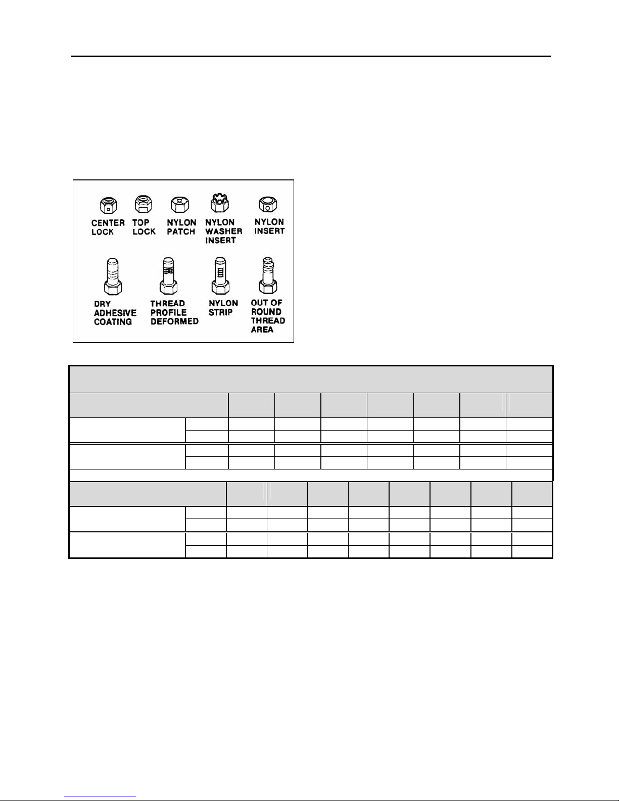
A self-locking fastener is designed with an
interference fit between the nut and bolt threads.
This is most often accomplished by distortion of
the top thread of an all-metal nut or bolt or by
using a nylon patch on the threads. A nylon
insert or the use of adhesives may also be used
as a method of interference between nut and bolt
threads (Fig. 16).
FIGURE 16 : SELF-LOCKING FASTENERS 00004
5.2 RECOMMENDATIONS FOR REUSE
Clean, unrusted self-locking fasteners may be
reused as follows:
a) Clean dirt and other foreign matter from the
fastener;
b) Inspect the fastener to ensure there is no
crack, elongation, or other sign of fatigue or
overtightening. If there is any doubt, replace with
a new self-locking fastener of equal or greater
strength;
c) Assemble parts and hand start fastener;
d) Observe that, before the fastener seats, it
develops torque per the chart in table two. If
there is any doubt, replace with a new selflocking fastener of equal or greater strength;
e) Tighten the fastener to the torque specified in
the applicable section of this manual;
Fasteners which are rusty or damaged should be
replaced with new ones of equal or greater
strength.
SELF-LOCKING FASTENER TORQUE CHART
METRIC
NUTS AND Nm 0.4 0.8 1.4 2.2 3.0 4.2 7.0
ALL-METAL BOLTS Lbf-in 4.0 7.0 12 18 25 35 57
ADHESIVE OR NYLON Nm 0.4 0.6 1.2 1.6 2.4 3.4 5.6
COATED BOLTS Lbf-in 4.0 5.0 10 14 20 28 46
US STANDARD
NUTS AND Nm 0.4 0.6 1.4 1.8 2.4 3.2 4.2 6.2
ALL-METAL BOLTS Lbf-in 4.0 5.0 12 15 20 27 35 51
ADHESIVE OR NYLON Nm 0.4 0.6 1.0 1.4 1.8 2.6 3.4 5.2
COATED BOLTS Lbf-in 4.0 5.0 9.0 12 15 22 28 43
5.3 SIX LOBED SOCKET HEAD
Six lobed socket head (Torx) fasteners are used
in some applications on vehicles covered in this
manual. The tools designed for these fasteners
are available commercially. However, in some
cases, if the correct tool is not available, a hex
socket head wrench may be used.
6 & 6.3 8 10 12 14 16 20
.250 .312 .375 .437 .500 .562 .625 .750
PA1561 9
Page 12
Section 00 : GENERAL INFORMATION
FIGURE 17: METRIC - US STANDARD CONVERSION TABLE 00005
PA1561 10
Page 13
Section 00 : GENERAL INFORMATION
FIGURE 18: CONVERSION CHART 00006
PA1561 11
Page 14
MULTIPLEX MODULES DISCONNECTION PROCEDURE PRIOR TO
WELDING
PROCEDURE NO: SAV060034
REVISION 4
2007-05-31
Material : N/A
Equipment(s) : Phillips-head screwdriver
Ratchet handle
3/8" socket
Electric tape
Long nose pliers
Reference schematics: N/A
Safety rules : - Wear safety goggles
- Set the battery master switch to the OFF position first
Recommendations: This procedure should be performed by qualified personnel only.
Effective
Revision 0 : Issued with multiplex
Revision 1 : Modified for Fire Protection System and also for VIP with multiplex
Revision 2 : Step 5 modified for introduction of VIP with multiplex -0436
Revision 3 : Step 1.15 added C397
Addition of SECTION 2 for X3 Coaches
Addition of SECTION 3 for XLII MTH
Revision 4 : Modified for introduction of CPC module for VIP,H3 Coach, X3 7-0942VIP
8-1037 H3
8-9282 X3
Page 1 de 15
Page 15
PROCEDURE NO: SAV060034 REVISION 4
SECTION 1 H3 Coaches & VIP
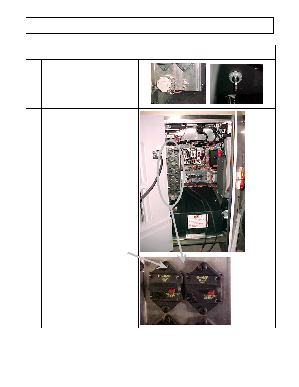
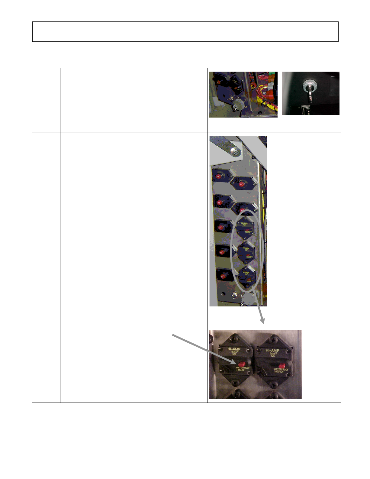
1.00
Location: Main power compartment and
dashboard
Set the battery master switch to the OFF
position.
Place the ignition switch to the OFF
position.
1.05
Location: Main power compartment
Trip circuit breakers CB2, CB4, CB6
Push the red button to open the circuit
Page 2 of 15
Page 16
PROCEDURE NO: SAV060034 REVISION 4
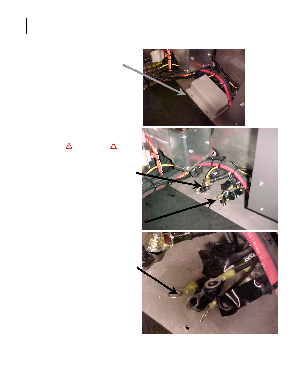
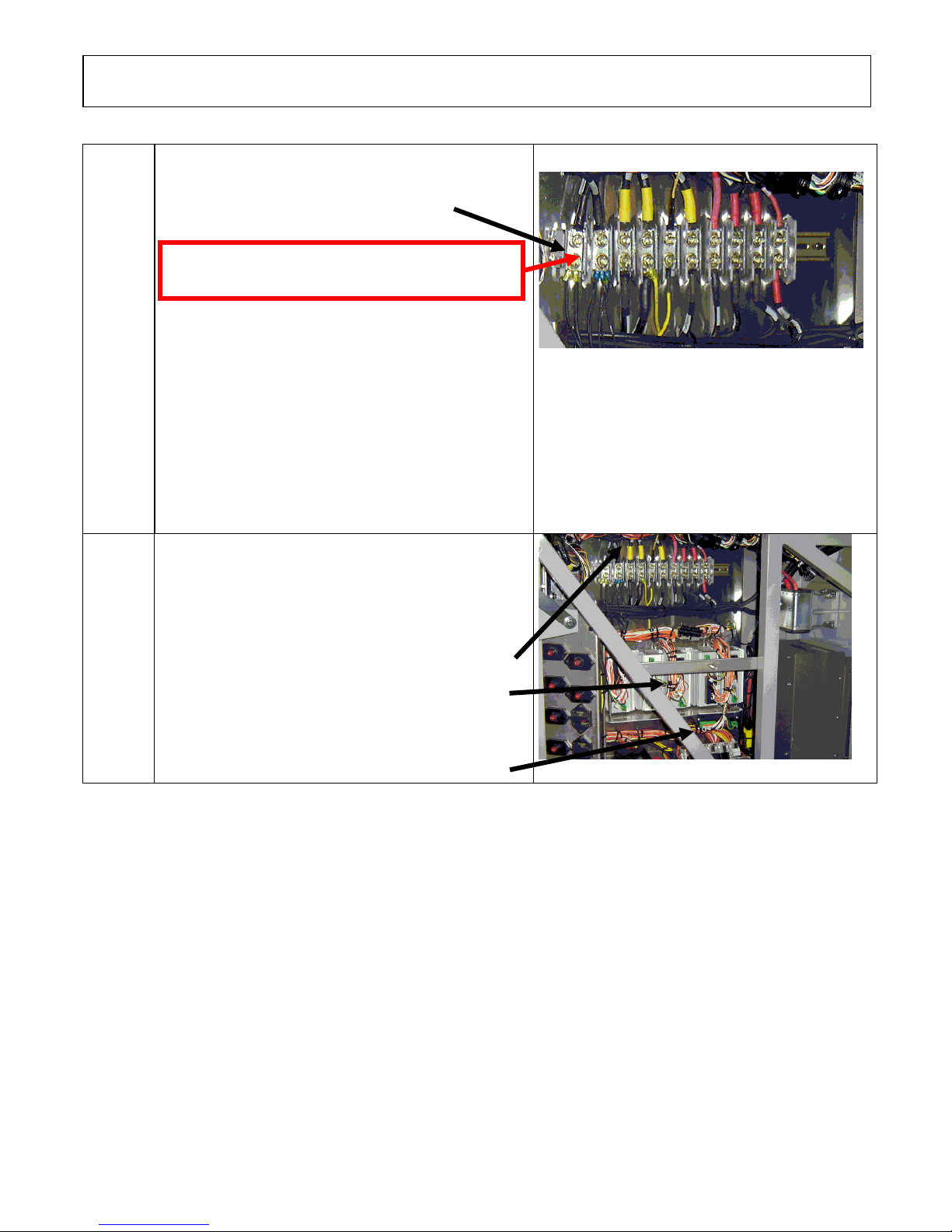
1.10
Location: Main power compartment
Remove the protective cover
WARNING
LIVE WIRE
This 12-volt terminal remains
energized
Disconnect the electronic ground terminals
from the stud
Using electric tape, insulate the 2 largest
gage wires. Make sure the ring terminals
do not touch each others and the vehicle
body.
NOTE
With disconnection of the electronic
ground terminals, disconnecting the
engine ECM, transmission TCM and the
dashboard electronic components
(telltale module, HVAC module, radio,
control head, …) is not required.
Page 3 of 15
Page 17
PROCEDURE NO: SAV060034 REVISION 4
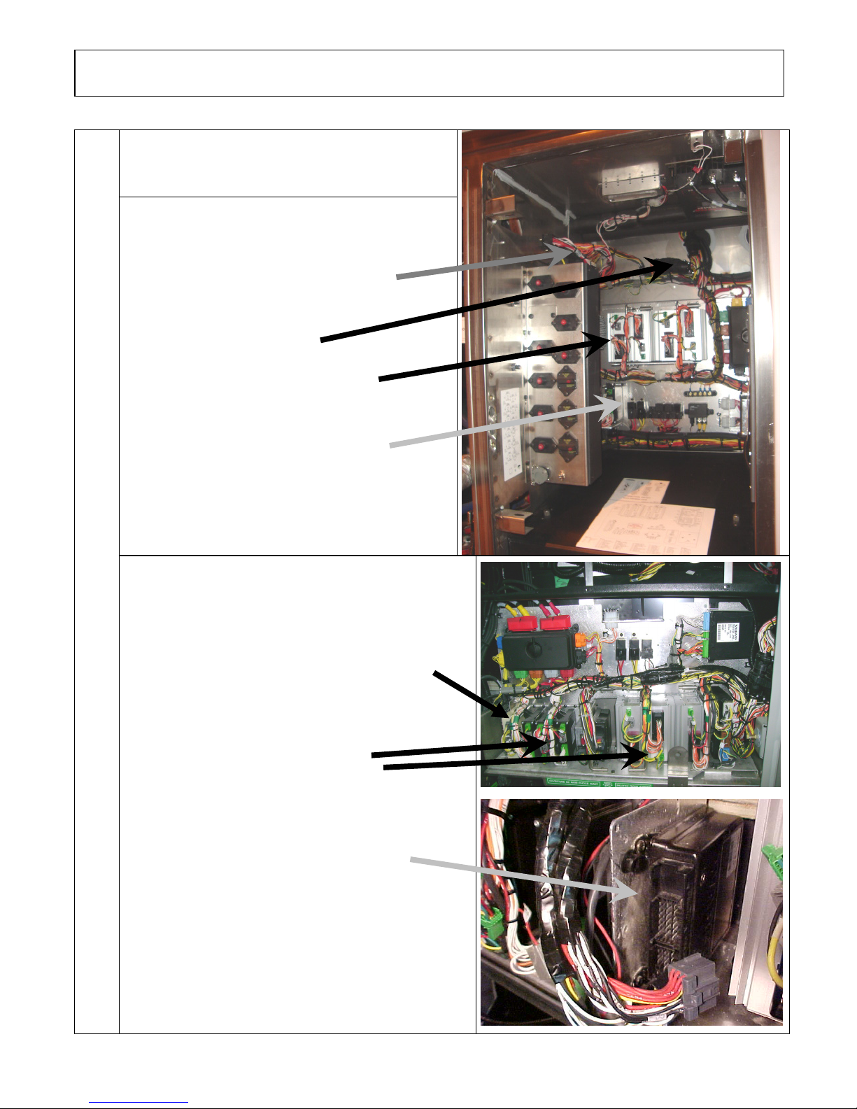
1.15
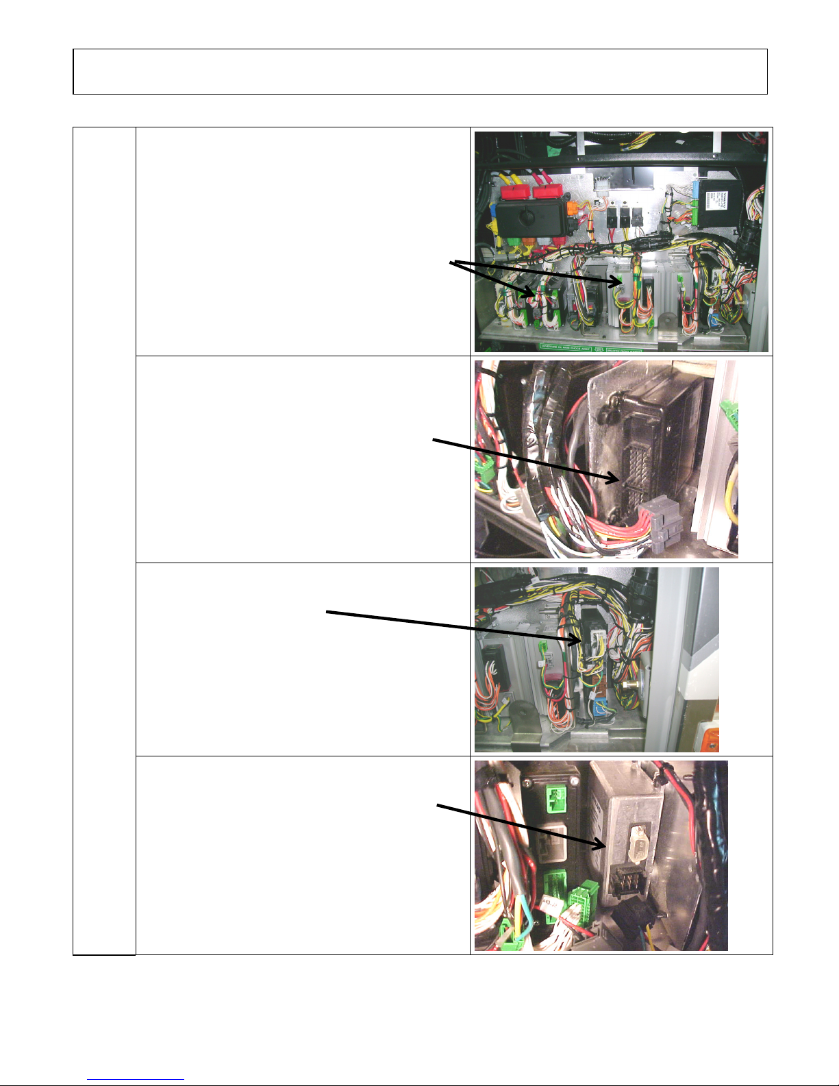
Location: Main power compartment
Disconnect the electronic modules :
Disconnect the I/O A and I/O B modules
1.20
Disconnect connector C717
Unplug 3 connectors per I/O B modules
Unplug 3 connectors on the I/O A module
Disconnect C397
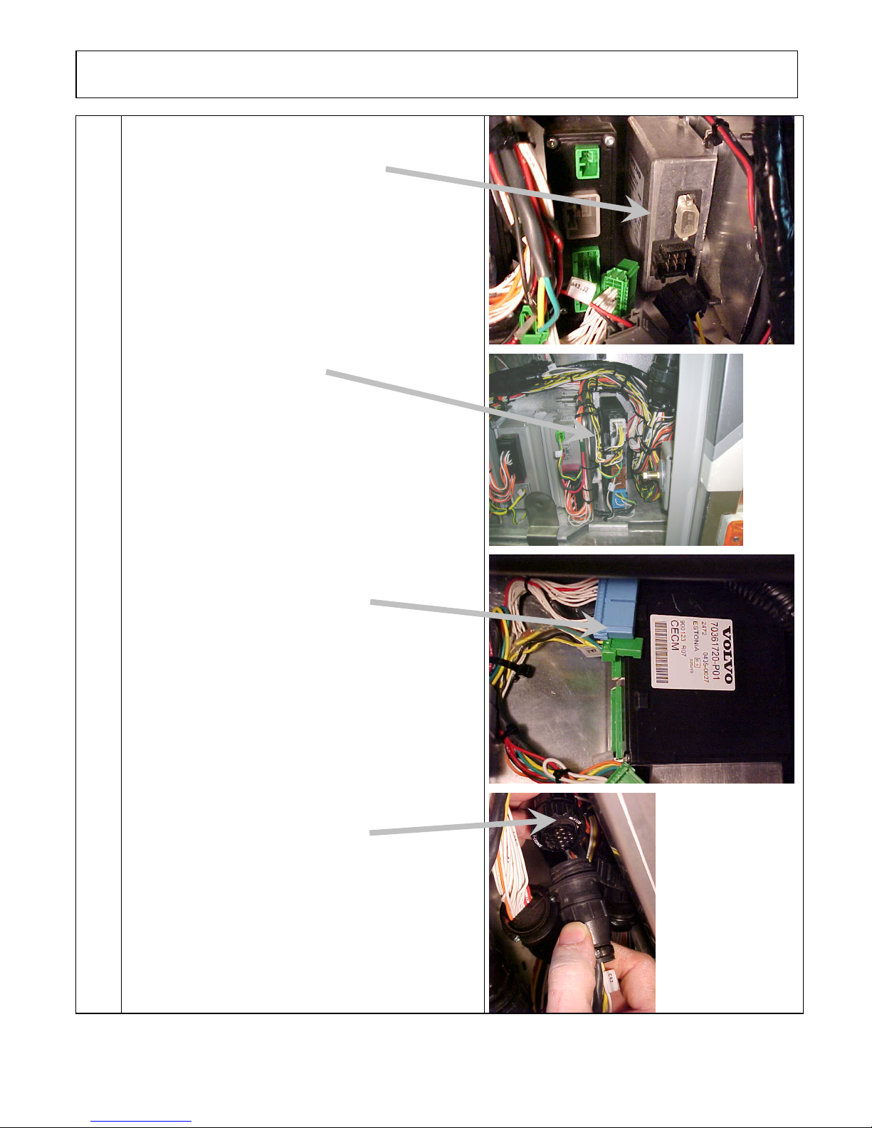
Location: Front electrical compartment
VIP + COACH: Disconnect the I/O A, I/O B, ABS,
master ID, CECM and CPC modules. Unplug connector
C92
VIP: Disconnect all keyless module connectors.
Unplug 3 connectors per I/O B modules
and 3 connectors per I/O A modules.
Unplug 2 connectors from the ABS module
Page 4 of 15
Page 18
PROCEDURE NO: SAV060034 REVISION 4
Unplug 1 connector from the master ID
Disconnect CPC connectors
Unplug 3 connectors from the CECM
Unplug connector C92
Page 5 of 15
Page 19
PROCEDURE NO: SAV060034 REVISION 4
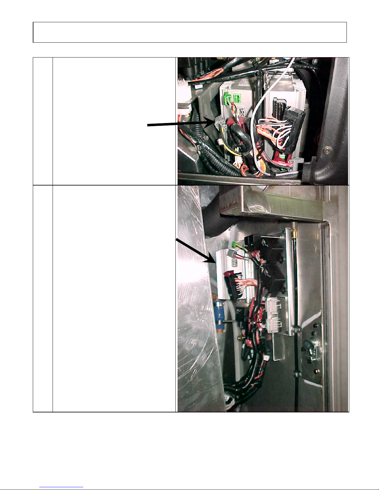
1.25
Location: pneumatic accessory panel
inside right console
Remove the access panel on the right
console (R.H. side of dashboard)
Disconnect both I/O B modules
1.30
Location: Evaporator compartment
Remove the protective cover and
disconnect the I/O B module
Page 6 of 15
Page 20
PROCEDURE NO: SAV060034 REVISION 4
1.40
Kidde Automatic Fire Detection and
Suppression System (optional)
Disconnect C466
Kidde AFSS module is located on the
lateral control panel.
1.45 When all the previous steps are done, you
can do welding on the vehicle
1.50
When welding is completed, reconnect
all the modules.
Make sure that the connectors locking tab
are well engaged
ENSURE THAT THE WELDING GROUND RETURN
CLAMP IS WELL SECURED AND MAKES A GOOD
ELECTRICAL CONTACT WITH A LARGE METALLIC
AREA OF THE CHASSIS LOCATED NEAR THE WELDING
POINT AS MUCH AS POSSIBLE.
BE CAREFUL TO MAKE THE PROPER CONNECTIONS, IF
NOT, SOME SYSTEMS OR COMPONENTS MAY NOT BE
USABLE
Page 7 of 15
Page 21
PROCEDURE NO: SAV060034 REVISION 4
SECTION 2 X3 Coaches
2.00
2.05
Location: Rear electrical compartment and
dashboard
Set the battery master switch to the OFF position.
Place the ignition switch to the OFF position.
Location: Rear electrical compartment
Trip circuit breakers CB2-CB4-CB6 located on rear
junction panel
Push the red button in to open the circuit
Page 8 of 15
Page 22
PROCEDURE NO: SAV060034 REVISION 4
2.10
2.15
Location: Rear electrical compartment
Disconnect the electronic ground terminals from this
stud
Warning: The remaining terminals may still be
energized
Use electric tape; make sure that cables do not touch
each others and the vehicle body.
NOTE
With disconnection of the electronic ground
terminals, disconnecting the engine ECM,
transmission TCM and the dashboard electronic
components (telltale module, HVAC module,
radio, control head, …) is not required.
Location: Rear electrical compartment
Disconnect the electronic modules:
Disconnect all I/O A and I/O B modules
Disconnect C397 and C717
Disconnect 3 connectors from each I/O B module
Disconnect 3 connectors from each I/O A module
Page 9 of 15
Page 23
PROCEDURE NO: SAV060034 REVISION 4
2.20
Location: front electrical compartment
Disconnect I/O A, I/O B, ABS, master ID, CECM and
CPC modules and also disconnect connector C92
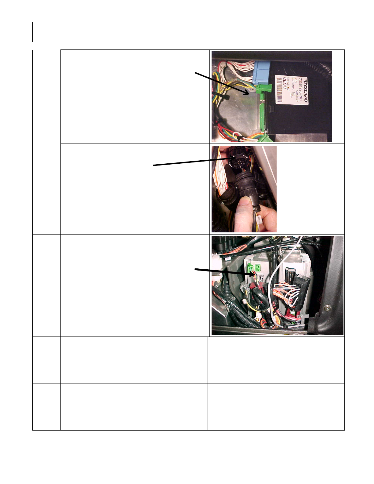
Disconnect the 3 connectors
from the I/O B and I/O A modules
Disconnect the 2 connectors from the ABS
module
Disconnect CPC connectors
Disconnect connector from master ID
Page 10 of 15
Page 24
PROCEDURE NO: SAV060034 REVISION 4
Disconnect the 3 connectors from CECM
Disconnect connector C92
2.25
2.30 When all the previous steps are done, you can do
2.40
Location: Entrance door & wiper control panel
Remove windshield wiper motor access
panel and disconnect both I/O B modules
welding on the vehicle
When welding is completed, reconnect all the
modules.
Make sure that the connectors locking tab are well
engaged!
ENSURE THAT THE WELDING GROUND
RETURN CLAMP IS WELL SECURED AND
MAKES A GOOD ELECTRICAL CONTACT
WITH A LARGE METALLIC AREA OF THE
CHASSIS LOCATED NEAR THE WELDING
POINT AS MUCH AS POSSIBLE
BE CAREFUL TO MAKE THE PROPER
CONNECTIONS, IF NOT, SOME SYSTEMS OR
COMPONENTS MAY NOT BE USABLE
Page 11 of 15
Page 25
PROCEDURE NO: SAV060034 REVISION 4
SECTION 3 XLII MTH
2.00
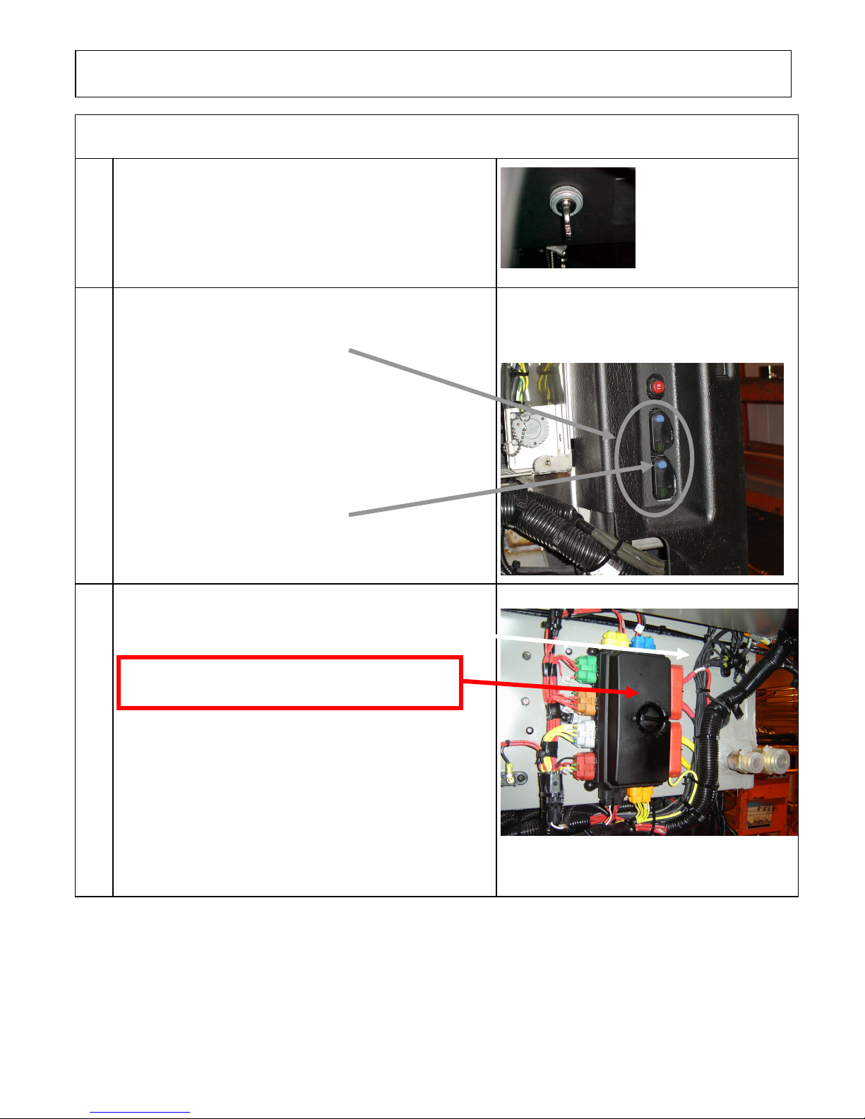
Location: Dashboard
Place the ignition switch to the OFF position.
2.05
Location: Engine compartment R. H. side area
Trip circuit breakers CB1-CB2 located on circuit breaker
panel.
Push the blue button in to open the
circuit
2.10
Location: Rear Junction Box
Disconnect the electronic ground terminals from this stud.
Warning: The remaining terminals may still be
energized.
Use electric tape; make sure that cables do not touch each
others and the vehicle body.
NOTE
With disconnection of the electronic ground terminals,
disconnecting the engine ECM, transmission TCM and
the dashboard electronic components (telltale module,
HVAC module, radio, control head, …) is not required.
Page 12 of 15
Page 26
PROCEDURE NO: SAV060034 REVISION 4
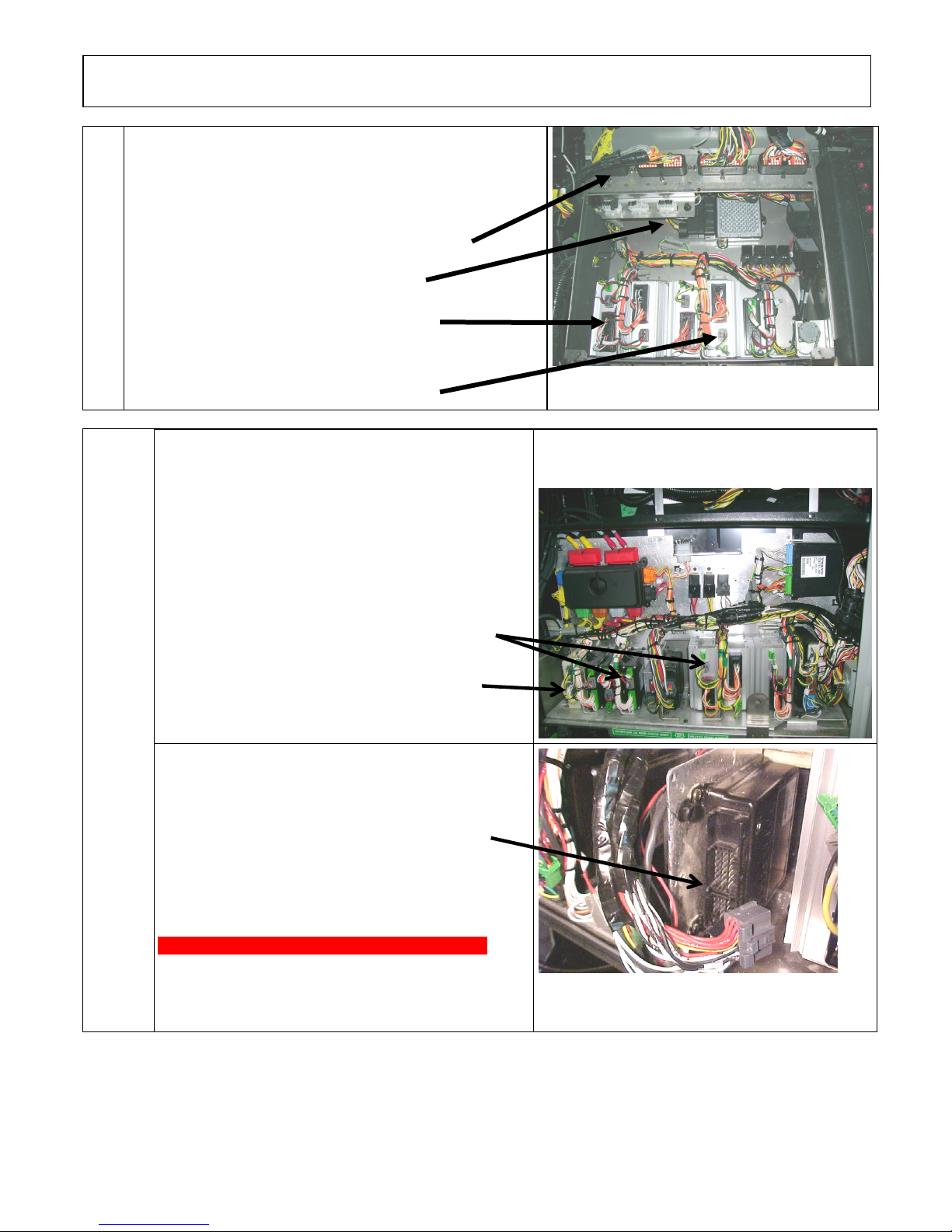
Location: Rear Junction Box
2.15
Disconnect the electronic modules:
Disconnect all I/O A and I/O B modules
Disconnect C397
Disconnect transmission module (A1)
Disconnect 3 connectors from each I/O B
Disconnect 3 connectors from each I/O A
2.20
Location: Front Electrical Compartment
Disconnect I/O A, I/O B, ABS, master ID, CECM,
CPC, keyless modules and also disconnect
connector C92.
Disconnect 3 connectors from the I/O B and
I/O A modules
Disconnect connectors from Keyless module
Disconnect 2 connectors from ABS module
Page 13 of 15
Page 27
PROCEDURE NO: SAV060034 REVISION 4
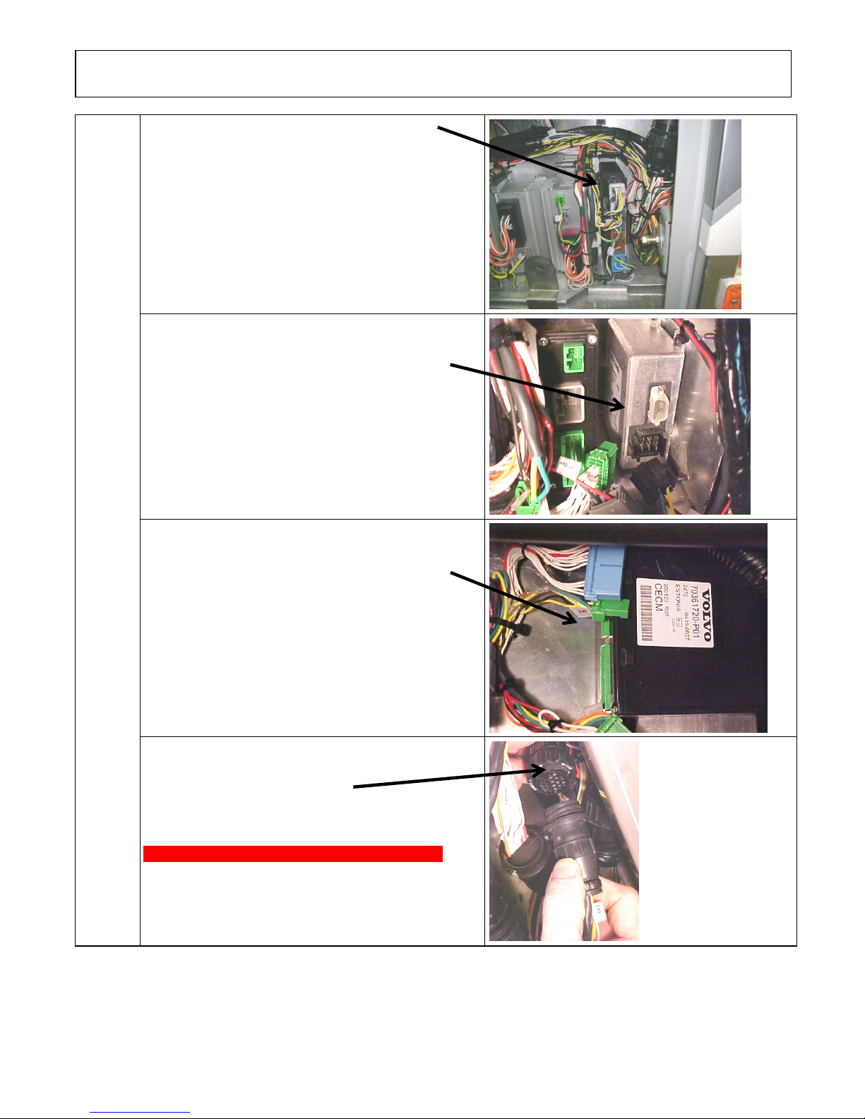
Disconnect connectors from CPC
Disconnect connector from master ID
Disconnect 3 connectors from CECM
Disconnect connector C92
Page 14 of 15
Page 28
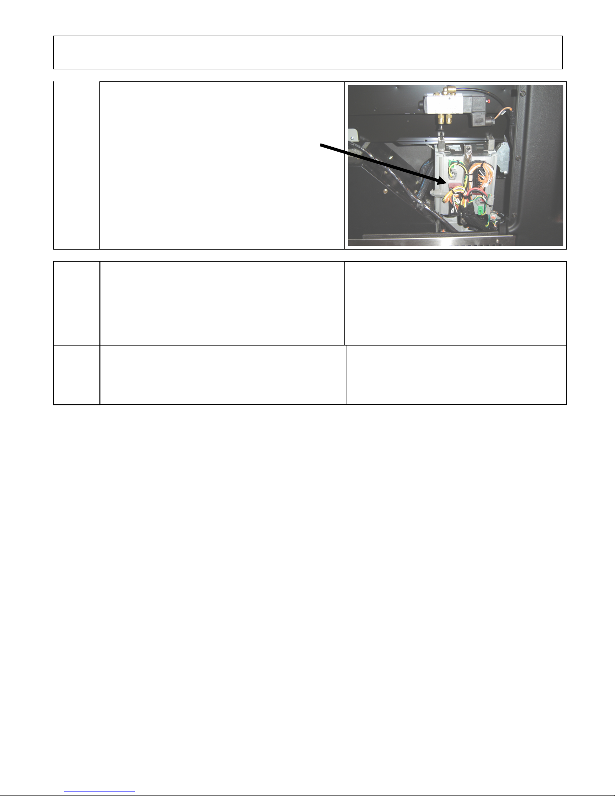
PROCEDURE NO: SAV060034 REVISION 4
Location: Wiper Control Panel
Remove windshield wiper motor access panel
And disconnect I/O B modules
2.30
When all the previous steps are done, you can do
welding on the vehicle
ENSURE THAT THE WELDING GROUND
RETURN CLAMP IS WELL SECURED AND
MAKES A GOOD ELECTRICAL CONTACT
WITH A LARGE METALLIC AREA OF THE
CHASSIS LOCATED NEAR THE WELDING
POINT AS MUCH AS POSSIBLE
2.35
When welding is completed, reconnect all the
modules.
Make sure that the connectors locking tab are well
engaged!
BE CAREFUL TO MAKE THE PROPER
CONNECTIONS, IF NOT, SOME SYSTEMS
OR COMPONENTS MAY NOT BE USABLE
Page 15 of 15
 Loading...