

Page 1
X32-6-C PreView™ System
QUICK INSTALLATION GUIDE
1
10335 W Emerald St
Boise, ID 83704
Phone 1.208.323.1000
Powered by
DOC. # 3700143D
10335 W Emerald St
Boise, ID 83704
Phone 1.208.323.1000
Powered by
Contents:
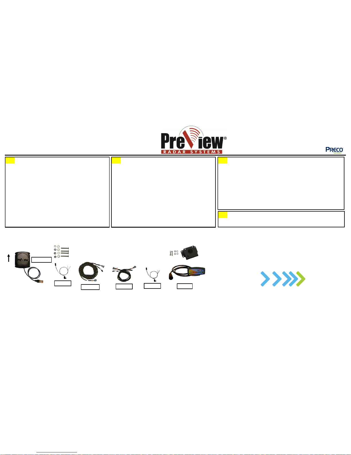
XPV4232A-6 Sensor (1)
Sensor Mounting Hardware (1)
Cables (4)
XPV41CA Cable (1), XPV41PA Cable 1’/0.3M (1)
XPV4132 32.8’/10.0M (1), XPV41RA Cable 3.3’/1M (1)
CD6 Display(1)
Display Mounting Hardware
User Manual
1
Select a location for the sensor approximately 3ft/1M from the ground.
Ideally the sensor should be centered on the rear of the vehicle.
Important!
Before the PreView Sensor is permanently installed to the vehicle,
verify the selected location provides a clear detection zone.
Temporarily attach the sensor in the proposed location, apply power to
the system, and verify nothing is detected.
Mounting
The sensor may be mounted directly on the vehicle or attached using a
bracket. Using the drill template, scribe position marks through the holes
and drill 1/4” (6mm) holes centered at the marks. A 1 1/2” diameter
clearance hole is required for the sensor connector and the mating cable.
Secure the sensor to the vehicle with the supplied hard ware. Apply a
maximum of 50 in-lbs to secure the sensor.
2
Before You Start
Mount Sensor
4
Routing the bod y harness should start at the rear of the veh icle and end in the cab. To
enter the cab, drill a 1 1/2” (38mm) hole and feed the connector through to connect to
the cab adapter.
Important!
The sensor mating connector is fully waterproof if mated properly. The
connectors with a collar (coupling ring) must be turned to the right until
they lock with the mating connector. Latch(es) on mating connector
must click (locking connectors together). Do not route cable next to heat
sources or area that may see abrasion or rock and debris damage. Bundle and
store any excess cable.
Install Cables
Contact Technical Support with Questions:
Telephone: 844.787.2327
Web: www.PreViewRadar.com
Email: [email protected]
The quick install guide is only a supplement to the product manuals. Please read all of the
manuals for complete information and instructions before installing the product.
Mount the display in a location easily viewed by the driver. Possible locations for the
display is on the dash or by either windshield pillar.
Mount Display
Back Page
Wire Connections
Wiring Diagram
XPV41CA
XPV4132
XPV41PA
XPV41RA
3
Note orientation:
THIS SIDE UP
XPV4232A-6
Sensor
Hardware
Not all hardware shown
CD6
DISPLAY
HARDWARE
Page 2
X32-6-C PreView™ System
QUICK INSTALLATION GUIDE
2
10335 W Emerald St
Boise, ID 83704
Phone 1.208.323.1000
Powered by
DOC. # 3700143D
Initial System Power Up and Test
Once the sensor and display are installed, wired, and connected, power should be
applied to test system operation. The vehicle must be placed in reverse to
power up the system, the green LED will be the only light illuminated (the 3rd
yellow LED may flash once). If any of the detection (yellow) LED’s are lit, check
for any vehicle obstruction which may be detected by the sensor. If possible,
move the sensor so it does not detect the object(s). If it is not possible to relocate
the sensor contact Preco Electronics, Inc™.
If for some reason the system is malfunctioning, the status LED will turn from
green to red, one of the yellow LEDs will be illuminated, and the buzzer will emit a
short stutter sound. Refer to the Troubleshooting section in the display manual to
determine the error and potential causes.
Once the system has been installed, the detection zone should be tested. The test
should be performed with two people, one who remains in the cab (the operator),
and one who walks through the sensor field to the rear of the vehicle (the
assistant). The operator engages the parking brake, presses the vehicle brake, and
places the vehicle in reverse. The assistant then walks through the detection zone
while the operator notes where the display buzzer activates. An accurate
detection zone can be mapped by moving about the rear of the vehicle and noting
when the display buzzer activates.
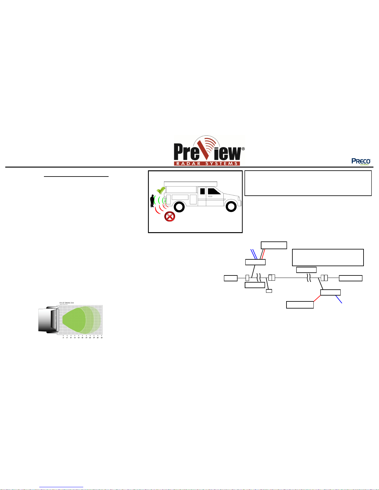
DETECTION AREA
NOT TO SCALE
The PreView® system is a blind spot collision warning system
designed to supplement other safety practices and/or devices. The
machine operator is always the first line of defense when safely
operating a vehicle.
TESTING / MAINTENANCE
Test the PreView
®
Radar System every day for functionality and performance
prior to vehicle operation, refer to the sensor manual.
Caution: The tilt angle of the sensor will determine the
detection zone of the radar.
Vehicle shown for reference
APPROXIMATE
PATTERN SHOWN
XPV41CA
XPV4232A-6
J2 No Connect
Red Wire to Ignition
Black wire to Ground
2 White Wires
No Connect
XPV4132
XPV41PA
XPV41RA
Allow a small service loop in the cables at
the display or sensor and secure the cables
every few feet (~1M) with tie wraps.
Red Wire to Reverse
CD6
White wire—No Connect
 Loading...