

Prevail-Catv WT-1550-DM Operating Manual
WT-1550-DM
Intelligent Direct Modulated
Optical Transmitter Operating Manual

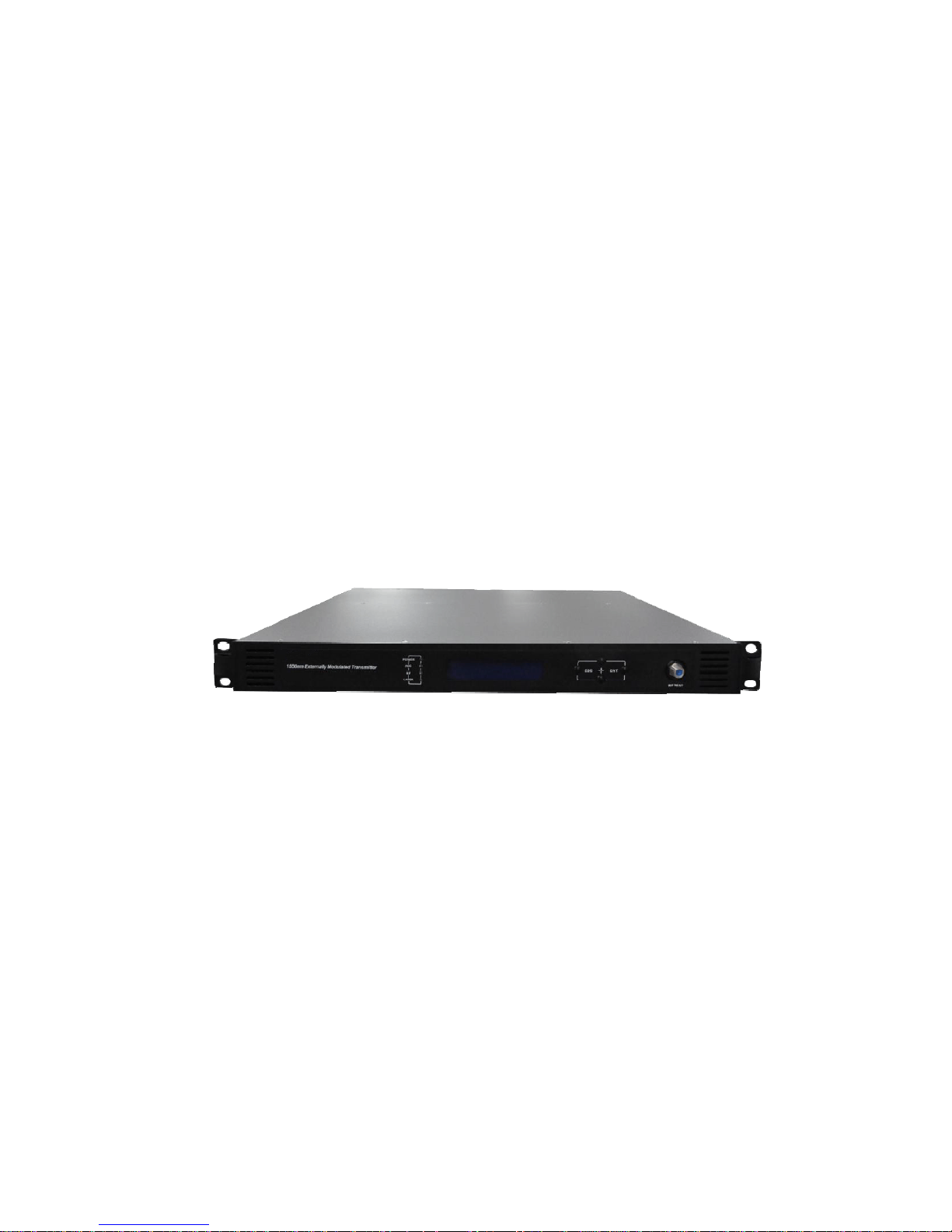
WT-1550-DM Intelligent Direct Modulated Optical Transmitter
Table of Contents
Table of Contents ...................................................................................................... - 1 -
1. Overview............................................................................................................... - 2 -
1.1 About This Manual ...................................................................................... - 2 -
1.2 Product Description ..................................................................................... - 2 -
1.3 Product Applications .................................................................................... - 3 -
2. Technique Parameters ........................................................................................... - 4 -
3. Panel Interface and Menu System Description ..................................................... - 5 -
3.1 Front Panel ................................................................................................... - 5 -
3.1.1 Indicator Description ......................................................................... - 5 -
3.2 Rear Panel .................................................................................................... - 6 -
3.3 Power Module.............................................................................................. - 6 -
3.3.1 220V Power Module .......................................................................... - 6 -
3.4 Menu Operation ........................................................................................... - 7 -
3.4.1 Main Menu......................................................................................... - 7 -
3.4.2 Display Menu..................................................................................... - 8 -
3.4.3 Set Menu .......................................................................................... - 10 -
3.4.4 Alarm Menu ..................................................................................... - 11 -
4. Installing the WT-1550-DM Optical Transmitter ............................................... - 12 -
4.1 Receiving and Inspecting........................................................................... - 12 -
4.2 Precautions ................................................................................................. - 12 -
4.3 Mounting WT-1550-DM............................................................................ - 12 -
4.3.1 Mounting the WT-1550-DM in the Rack......................................... - 12 -
4.3.2 Connecting the RF Cables ............................................................... - 12 -
4.3.3 Connecting the Optical Fiber Cables ............................................... - 13 -
4.3.4 Connecting the Ethernet Cable ........................................................ - 13 -
4.3.5 Connecting Power ............................................................................ - 13 -
5. Communication Setup......................................................................................... - 14 -
5.1 RS232 Communication Interface Description ........................................... - 14 -
5.2 Set up the Hyper Terminal ......................................................................... - 14 -
5.3 Operating Parameters Configuration ......................................................... - 16 -
5.4 Remote Monitoring: SNMP ....................................................................... - 19 -
6. Maintenance and Troubleshooting ...................................................................... - 20 -
6.1 Cleaning Fiber Optic Connectors............................................................... - 20 -
6.1.1 Cleaning Patch Cord or Pigtail Fiber Optical Connectors ............... - 20 -
6.2 Troubleshooting ......................................................................................... - 21 -
6.3 After-sales Service Description.................................................................. - 21 -
6.4 Disclaimer .................................................................................................. - 21 -
- 1 -

WT-1550-DM Intelligent Direct Modulated Optical Transmitter
1. Overview
1.1 About This Manual
This instruction manual is a complete guide to install and operate the (1RU)
WT-1550-DM optical transmitter. Please read the entire manual before beginning
installation.
This manual applies to WT-1550-DM optical transmitter.
• Chapter 1 gives general information about the WT-1550-DM optical transmitter.
• Chapter 2 describes the complete technical specifications of WT-1550-DM.
• Chapter 3 describes the front/rear panel interfaces and menu system.
• Chapter 4 tells you how to install WT-1550-DM optical transmitter.
• Chapter 5 tells you the communication setting of WT-1550-DM.
• Chapter 6 describes maintenance and what to do in the event of problems.
1.2 Product Description
WT-1550-DM intelligent directly modulated optical transmitter is mainly used in
1550nm optical fiber transmission system. Adopt advanced electronic dispersion
compensation technology, accurately compensate according to the actual transmission
distance by 1km stepping. The maximum compensated distance up to 50km.
WT-1550-DM intelligent directly modulated optical transmitter is the most
important equipment to construct the CATV network. It mainly used for the
value-added services of TV image signal, digital television signal, telephone voice
signal and data (or compressed data) signal. By built-in WDM, multiplex the inter-cut
optical signal and the main optical signal then output. After setting required optical
difference, the perfect adjustable optical attenuation function can automatic control
the inserted optical signal according to the main optical signal, realize inter-cut system
full automatic adjustment. Provide high quality low cost solution for all-optical relay
1550 optical fiber CATV system, and local value-added services inter-cut.
Characteristics:
1. Patent pre-distortion circuit.
2. The optical fiber distance is adjustable according to the actual use condition by
1km stepping.
3. WT-1550-DMⅡ: Built-in WDM, multiplex the inserted optical signal and the
main optical signal then output.
4. WT-1550-DM Ⅲ: Built-in WDM and adjustable attenuator.
- 2 -
WT-1550-DM Intelligent Direct Modulated Optical Transmitter
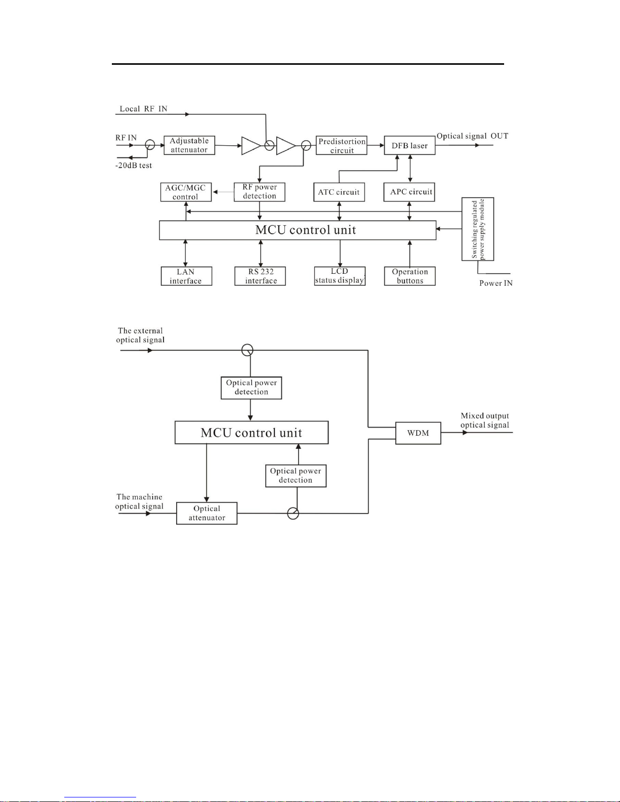
Block Diagram
WT-1550-DM directly modulated optical transmitter block diagram
WT-1550-DM inter-cut part block diagram
1.3 Product Applications
• 1550nm Optical fiber transmission system
• Construct the CATV network
• Local value-added services inter-cut
- 3 -

WT-1550-DM Intelligent Direct Modulated Optical Transmitter
2. Technique Parameters
Item Unit Technique Parameters
Output optical power mW 10
Optical wavelength nm
Dispersion compensation
distance
Laser type
Optical modulation mode
Optical connector type
Km ≤50
Frequency range MHz 47-862/1003
RF input level dBuV 75-85
Flatness in band dB ±0.75
RF input impedance Ω 75
Input return loss dB ≥ 16
C/CSO dB ≥ 60
C/CTB dB ≥ 65
C/N dB ≥ 51
AGC control range dB ±5
MGC control range dB 0-20
Supply voltage V AC 110V-250V (50Hz)
Consumption W 30
Operating temperature
Storage temperature
℃
℃
Relative humidity % Max 95% no condensation
Dimension mm
Special instructions: The performance parameters of this manual according to the
measuring method of GY/T 143-2000 <Specifications and methods of measurement
on AM optical transmitter and receiver used in CATV systems>, and tested under the
specified test conditions.
1550±10 (have to be ITU wavelength when
with inter-cut function)
DFB laser
Direct optical intensity modulation
FC/APC or SC/APC
25Km optical fiber, 0dB
received
0 -- 45
-20 -- +65
483(L)×380(W)×44(H)
- 4 -
r
)
WT-1550-DM Intelligent Direct Modulated Optical Transmitter
3. Panel Interface and Menu System Description
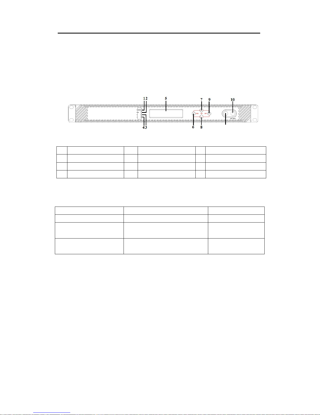
3.1 Front Panel
11
Front panel schematic diagram
1
4
7
10
Power indicator
RF input indicator
UP key
RF output test port
2
5
8
11
Running indicator
LCD
DOWN key
Laser switch
3
6
9
Laser indicator
ESC key
Enter key
3.1.1 Indicator Description
Power indicator (POWER) Power on LED green
Running indicator (RUN) Run normally LED flash green
Laser indicato
RF input indicator (RF
No output or exceed the normal range LED flash red
Laser OFF LED red
Laser ON LED green
Normal LED green
- 5 -
WT-1550-DM Intelligent Direct Modulated Optical Transmitter
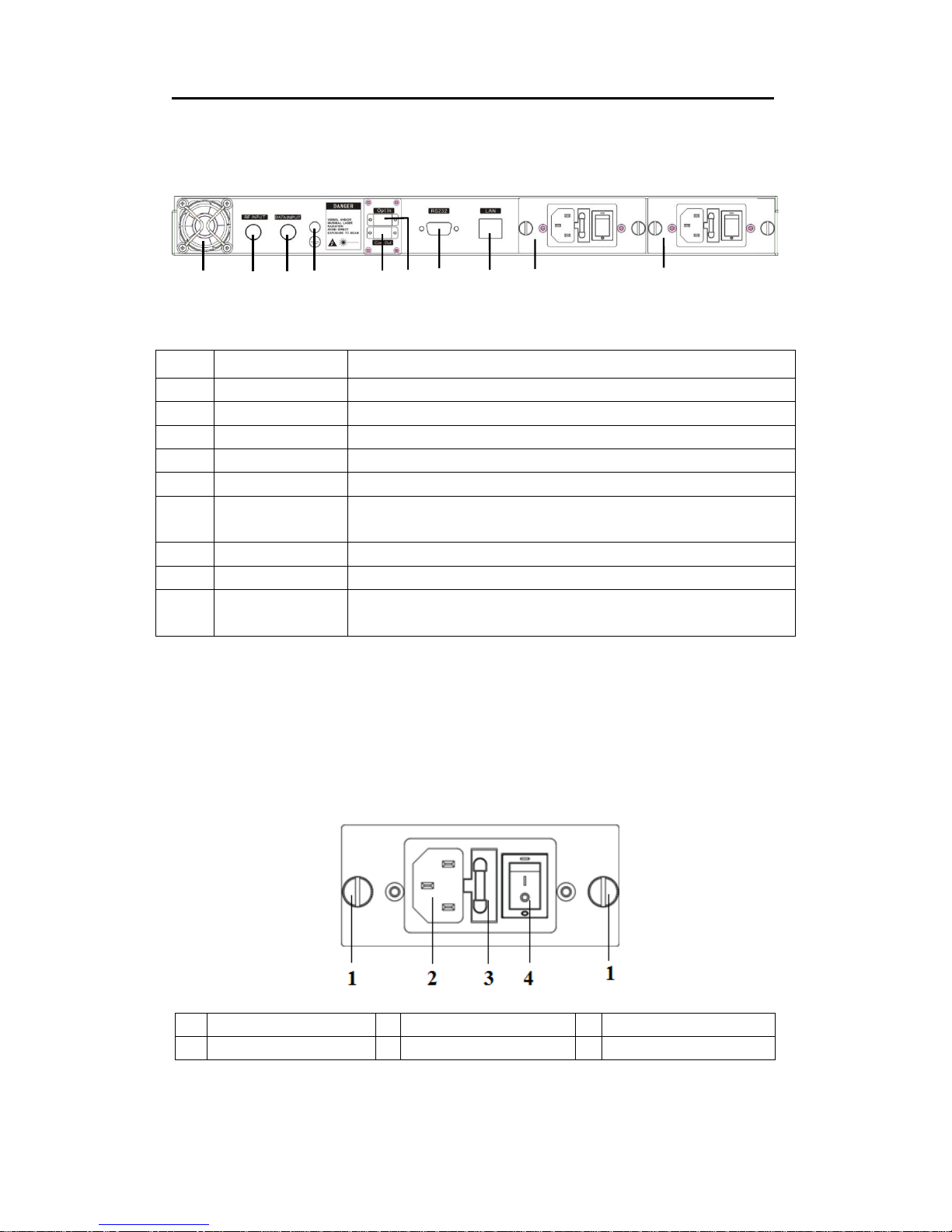
3.2 Rear Panel
6
1 2 3 4
5
Rear Panel schematic diagram
7
9
8
No. Name Remark
1
2
3
4
5
6
7
8
9
Fan
RF input
Local RF input Generally reserved
Ground stud Used for the connection of device and ground wire
Optical input Inserted optical signal input (without inter-cut function, no this port)
Optical signal
output
RS232 interface Used for configuring the network management parameters.
LAN interface Correspond to IEEE802.3 10Base-T, used for network management.
Switching power
supply
This interface is the optical signal output port of the device (If select
inter-cut function, this port is mixed output)
Hot plug
3.3 Power Module
9
3.3.1 220V Power Module
1
4
Mounting screws
Power switch
220V/110V power outlet
2
3
- 6 -
Fuse
 Loading...