

Prevail-Catv EN Series Installation Manual & Operation Manual

This water heater must be installed and serviced by a qualified person.
Please leave this guide with the householder.
Prevail Continuous Flow Gas Water Heater
Installation Guide & Operations Manual
EN Series
FOR EXTERNAL INSTALLATION ONLY
WaterMark
™
GMK10177
WMKA22451
Thank you very much for purchasing our water heater. Before installing and
operating your water heater, please read this manual carefully and keep it
for future reference.
N30248

CONTENTS
1. IMPORTANT........................................................................................................................................2
2. FOR THE INSTALLER ........................................................................................................................ 2
3. FOR THE SERVICEMAN.................................................................................................................... 2
4. FOR THE PLUMBER ..........................................................................................................................2
5. SPECIFICATION .................................................................................................................................3
6. INTRODUCTION................................................................................................................................. 4
7. DIMENSIONS AND CONNECTION POINTS...................................................................................... 5
8. SAFETY GUIDELINES........................................................................................................................ 6
9. INSTALLATION ...................................................................................................................................7
10. CONFIRM THE APPLIANCE SUITABILITY...................................................................................... 7
11. ABOUT SELECTING AN INSTALLATION LOCATION ......................................................................8
12.CLEARANCES FOR OUTDOOR HEATER LOCATIONS ................................................................. 9
13. GAS CONNECTION......................................................................................................................... 10
14. SIZING AND CONNECTING............................................................................................................ 10
15. MEASURING INLET GAS PRESSURE AND TESTING GAS LEAKAGE........................................ 11
16. WATER CONNECTIONS ................................................................................................................. 11
17. ELECTRICAL CONNECTIONS........................................................................................................ 13
18. REMOTE CONTROLLER ................................................................................................................ 14
19. REMOTE CONTROLLER INSTALLATION ......................................................................................15
20. CONNECTION OF REMOTE CONTROLLER WIRING TO THE WATER HEATER ........................ 16
21. INITIAL OPERATION ....................................................................................................................... 17
22. NORMAL OPERATION ....................................................................................................................17
23. WITHOUT REMOTE CONTROLLER............................................................................................... 18
24. WITH MULTIPLE REMOTE CONTROLLER .................................................................................... 19
25. FREEZE PREVENTION................................................................................................................... 20
26. WINTER SHUTDOWN ....................................................................................................................20
27. MAINTENANCE AND SERVICE ......................................................................................................21
28. UNIT DRAINING AND FILTER CLEANING...................................................................................... 21
29. GENERAL TROUBLESHOOTING ...................................................................................................21
30. PCB ERROR CODES ......................................................................................................................23
31. WIRING DIAGRAM ..........................................................................................................................24
32. WATER FLOW AND WATER TEMPERATURE................................................................................ 24
33. WARRANTY CONDITIONS..............................................................................................................24
COVER PAGE
1

WARNING
1.1 FOR THE INSTALLER
1.2 FOR THE SERVICEMAN
1.3 FOR THE PLUMBER
The installation must be done in accordance with the information supplied in this manual. All other relevant
national, state and local regulations must also be conformed with and these include (but are not limited to):
Maintenance and fault-finding must be done in accordance with these instructions and the applicable
regulations listed above.
Australian Standard AS3498: 2009 Hot Water Supply
Australian Standard AS3500.1 – Water Services.
Australian Standard AS3500.4 – Heated Water Services.
Australian Standard AS3000 – Electrical Installation.
Australian Standard AS/NZS5601 – Gas Appliance Installation.
Local Water, Gas & Electrical Authority Regulations.
Municipal Building Codes including local OH&S requirements.
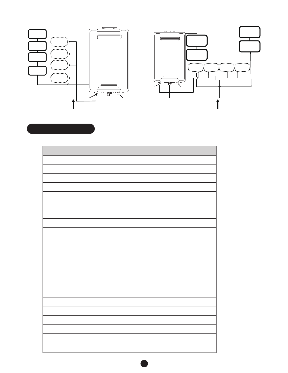
Total length to first tap or outlet is required to be a minimum of 2 meters from the outlet connection of
the water heater.
Installation and service must be performed by a qualified installer (for example, a licensed
plumber or gas fitter).
●
●
●
●
●
●
●
●
Pipe size is nominal 15mm from hot water outlet to the first tap or outlet.●
Gas pipe size is nominal 20mm.●
!
When connecting the hot water supply to the fixtures in the property a minimum of two (2) metres of
pipework must be used between the outlet of the water heater and the first tap and outlet. See Diagram
below.
The hot water line should be insulated with Armaflex or similar pipe insulation.
●
●
When the installation is completed the temperature is to be tested at the taps to confirm the water
temperature does not exceed the required 50℃ setting.
●
2
1. IMPORTANT
This manual has been prepared for Installers and Servicemen of the equipment. Please keep it in a safe
place for future reference.
PLEASE NOTE EN20CF-LP70&EN20CF-NG70 model is supplied factory pre-set at 70℃ maximum outlet
water temperature to comply with the requirements of AS 3498 Clause 7.2.2.
Model number EN20CF-LP70 & EN20CF-NG70 unit does require a temperature control device to be
installed.
Please follow all the installation instructions in the Installation and operating instructions handbook and the
following additional instructions for the water heater outlet connection.
3
2. SPECIFICATIONS
TECHNICAL DATA AND DIMENSIONS EN Series
Gas Type NG LPG
Model EN20CF-NG70 EN20CF-LP70
Gas Input(MJ/h) 160 160
Inlet Pressure(kPa) 1.13 2.75
Main Injector(mm) φ1.65 φ0.96
Test Point Pressure
High/Low(kPa)
0.65/0.10 1.85/0.17
Water Heating Capacity
(Raised 25℃)
20.0L/min 20.0L/min
Max. Water Pressure(kPa)
1000 1000
Min. Water Pressure Required To
Operate The Water Heater(kPa)
150 150
Relief Valve Pressure Setting(kPa)
1200 1200
Gas Connection R3/4(20mm)
G1/2(20mm)Water Connections
Ingress Protection Rating(
AS60529)
IPX4
Ignition Electronic
Rated Voltage: AC.240V/50Hz
Net Weight(kG) 14.2
Gross Weight(kG) 16
Product Dimensions(mm) 595 x 375 x 165
Package Dimensions(mm)
IAPMO Gas Mark Approval Number
IAPMO Water Mark Approval Number WMKA22451
GMK10177
748 x 420 x 230
HOT WATER
OUTLET
COLD WATER
INLET
GATE OR BALL
VALVE ON INLET
ENSUITE
LAUNDRY
BATHROOM
KITCHEN
Water Controller
(optional)
Water Controller
(optional)
Water Controller
(optional)
Water Controller
(optional)
50ºC Appliance Minimum length of pipe from hot
outlet to nearest hot water tap 2 meters
HOT WATER
OUTLET
COLD WATER
INLET
GATE OR BALL
VALVE ON INLET
ENSUITE
LAUNDRY
BATHROOM
KITCHEN
Water Controller
(optional)
Water Controller
(optional)
Water Controller
(optional)
Water Controller
(optional)
TCD
Not a 50ºC Appliance
Note:TCD=Temperature Control Device
This manual provides information necessary for the installation, operation, and maintenance of the
water heater.
●
The model description is listed on the name plate which is attached to the right side of the case of the
water heater. (Please refer to p.8)
●
Please read all installation instructions completely before installing this product. ●
The Water Heater is an instantaneous, water heater designed to efficiently supply endless hot water
for the demand.
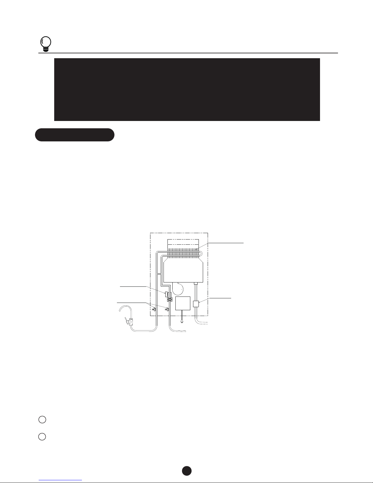
This diagram illustrates the water heater design concepts only and is not accurate to the one physical description.
●
The principle of the water heater is shown below: ●
4
3. INTRODUCTION
NOTES
The appliance will operate at reduced performance below 340 kPa water pressure.
For information relating to burner test point pressures and injector sizes refer to the name
plate located on the right hand side of the case for each model. (please refer to p.8)
For information relating to overall dimensions and connection points refer to diagrams.
(Please refer to p.6)
Before installing in areas over 1500 m above sea level, contact the manufacturer for
instructions.
Gas valve
A hot water tap is turned on.
①
②
③
④
⑤
Water enters the water heater.
The water flow sensor detects the water flow.
The computer automatically ignites the burner.
Water circulates through the heat exchanger and then gets hot.
The computer will modulate the gas supply valve and water flow to produce the right amount of hot
water at the correct temperature.
When the tap is turned off, the unit shuts down.
6
7
Heat exchanger
Thermistor
Fan
Computer
board
Hot water outlet
Cold water inlet
Gas
AC240V
●
●
●
Flow sensor
Exhaust
Burner
5
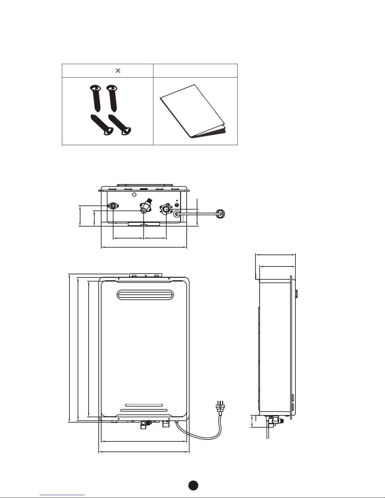
3.1 ACCESSORIES
Check that the installation and operation manual and screws are included with the unit.
Screws
×
4
Manual
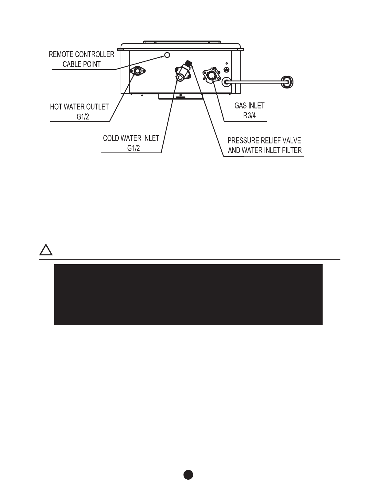
DIMENSIONS
DIMENSION AND CONNECTION POINTS
●
165
610
592
560
148
50
377
356
355
127 94
70
84
64
6
●
●
●
WARNING
Installation and service must be performed by a qualified installer (for example, a licensed
plumber or gas fitter).
The installer (licensed professional) is responsible for the correct installation of the water
heater and for compliance with all relevant national, state and local regulations.
The water heater must be installed OUTDOORS ONLY. DO NOT install the water heater
indoors.
Not to be used as a pool heater.
!
3.3 GENERAL
3.2 SAFETY GUIDELINES
CONNECTION POINTS
Ensure the following warnings and instructions are read and understood before commencing
installation.
Carefully plan where you intend to install the water heater. Please ensure:
The water heater will be located in an open air environment with natural ventilation;
Locate the water heater where water leakage will not damage surrounding areas and remove any
transit protection.
Check the name plate and gas type label for the correct GAS TYPE, GAS PRESSURE, WATER
PRESSURE and ELECTRIC RATING;If this unit does not match operating condition, do not install
and consult with manufacturer.
If any problem should occur, turn off all hot water taps and turn off the gas. Then call a trained
technician or the gas Company or the manufacturer
.
●
●
●
●
7
4.1 CONFIRM THE APPLIANCE SUITABILITY
WARNING
Water temperatures above 50 ℃ can cause severe burns or death from scalding. Children,
the disabled and the elderly are at a high risk of being injured. Feel the water temperature
before bathing or showering. Do not leave children, disabled persons, or the elderly
unsupervised. The Australian Standards AS 3498 gives full details of the requirements for
supply of controlled temperature to ablution outlets (bathrooms) and is required to be
conformed to under all plumbing codes within Australia.
!
PROHIBITED
4. INTRODUCTION
The water heater requires careful and correct installation to ensure safe and efficient operation.
This manual must be followed . Read the “SAFETY GUIDELINES” and the “IMPORTANT”
sections at the beginning of this manual.
Check the gas type label and the name plate for the correct gas type, gas pressure, water pressure
and electrical rating for your application. Do not install this unit if these requirements are not met.
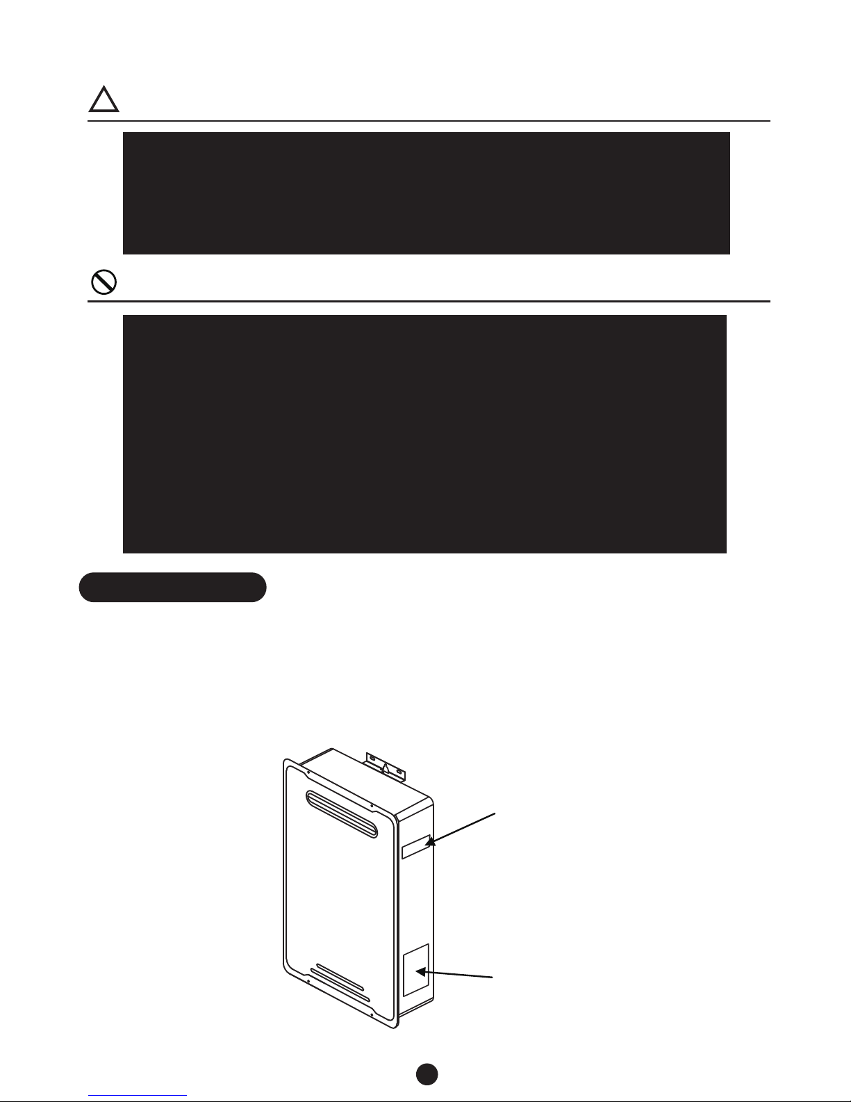
Gas Type Label
Position on Case
Rating Label Position
on Case
Do not store or use gasoline or other flammables, vapors, or liquids in the vicinity of this
appliance.Vapors from flammable liquids will explode and catch fire causing death or
severe bums.
Do not reverse the water and/or gas connections as this will damage the gas valves and
can cause severe injury or death. Follow the diagram on p. 11 and 13 when installing your
water heater.
Do not use this appliance if any part has been in contact with or been immersed in water.
Immediately call a licensed plumber, a licensed gas fitter, or a professional service
technician to inspect and/or service the unit if necessary.
Do not disconnect the electrical supply if the ambient temperature will drop below freezing.
The Freeze Prevention System only works if the unit has electrical power. The warranty
will not be covered if the heat exchanger is damaged due to freezing. Refer to the section
on the Freeze Prevention System on p. 21 for more information.
●
●
●
●
●
 Loading...