

Presys PCON-Y17 Series, PCON-Y17-DT, PCON-Y17-RM Technical Manual
®
presys
®
G
A
N
A
M
S
T
E
M
Q
Y
U
T
I
A
L
N
E
T
M
S
E
Y
PCON-Y17
Pressure Controller
Technical Manual
EM0288-02
Series
PCON-Y17
Description
Pressure Controller
LVD
Low Voltage Directive
2006/95/EC of the European Parliament and of the Council of 12 December 2006 on
the harmonization of the laws of Member States relating to Electrical Equipment
designed for use within certain voltage limits.
EN 61010-1
Safety requirements for electrical equipment for measurement, control and laboratory
use – Part 1: General Requirements.
EN 61010-2:010
Safety requirements for electrical equipment for measurement, control and laboratory
use - Part 2-010: Particular requirements for laboratory equipment for the heating of
Materials.
EMC directive
2004/108/EC of the European Parliament and of the Council of 15 December 2004
on the approximation of the laws of the Member States relating to electromagnetic
compatibility and repealing Directive 89/336/EEC
EN 61326-1
Electrical equipment for measurement, control and laboratory use - EMC requirements
– Part 1: General Requirements.
Vinicius José Gomes Nunes
Antonio Rafael Sito Antunes
CEO
Engineering Manager
presys
EC Declaration of Conformity
We declare under our sole responsability that the CE marked products, are in conformity
with the essential requirements of the following EC Directives when installed in
accordance with the installation instructions contained in the product documentation:
São Paulo, 8 September 2015
PRESYS Instruments PCON-Y17
WARNING!
The instruments described in this technical manual are equipments for
configuration and selection of values of the parameters of the
Use the instrument only according to this technical
WARNING!
Do not apply pressure above 130% of full scale of the control range (for
the range of 3000 psi, do not apply pressure above 110% of full scale
control range).
WARNING!
Be careful with the pressure connections. High pressures with a large
WARNING!
When a vacuum pump is attached to the negative supply port of the
the negative
WARNING!
Other pressure equipments and accessories (such as hose, reservoirs,
WARNING!
During startup, do not connect any instrument to the output port of the
connections to the Pressure
presys
use in specialized technical area. The user is responsible for the
instruments. The manufacturer warns against the risk of incidents with
injuries to both persons and prope rty, resulting from the incorrect use of
the instrument.
manual. Any operation not described here is not allowed.
volume can cause damage to both persons and property.
Apply to the positive supply port pressure between 110% and 130% of
the full scale of the control module (fo r the 3000 psi range, the positive
pressure supply should be between 104% and 110%).
The pressure supply must be pneumatic, dry and clean air, nitrogen or
inert gases.
pressure control module, it is strongly recommended to u se a protection
valve to atmosphere in the vacuum pump. When controlling from a high
pressure to a low pressure the gas is exhausted through
supply port and can cause damage to the vacuum pump. Before going to
a low pressure, it is recommended to make a VENT operation.
protection devices) connected to the calibrator must b e ap propriate to the
working pressure.
Pressure Control Module. Before making
Control Module, enter the CALIBRATOR menu and wait for the automatic
VENT operation.

PRESYS Instruments PCON-Y17
WARNING!
The calibrator discharges gas to the atmosphere through the supply (-)
WARNING!
Before connecting the instrument under test to the output port, make a
WARNING!
Before connecting the instrument under test to the output port it is
recommended to configure the output range parameters. These
ge, in order to protect the
WARNING!
Avoid electric shock risk when to uching the equipmen t. Use on ly suitable
WARNING!
High voltage is present inside these equipments. It can cause great
damages and injuries. Do not make any repair service inside the
NOTICE!
High level of electromagnetic noise can cause instability to the
IMPORTANT!
All pressure equipment and accessories (such as hoses, connections,
) and out
presys
and vent ports. Leave these ports free.
The calibrator may produce high soun d levels when discharging gas. Use
a muffling device at the vent port.
VENT operation to discharge any gas inside the controller and go to
MEASURE mode. Before turning th e calibrator off, it is recommended to
vent the gas inside the controller.
parameters limit the controller output ran
instrument under test.
power cable with earth connection and never power up the equipment to
the mains socket without an earth connection.
equipment without removing the plug from the supply.
equipment. The equipment is provided with electromagnetic interference
filters that protect not only the mains but also the equipment itself against
noise. These filters have no function if the unit is not earthed properly.
adapters, etc.) connected to the calibrator must be clean, free of residues
such as oil, dirt, dust etc. These residues can cause irreversible damage
to the internal system of the pressure control module. It is mandatory to
use filters in both the pressure feed (SUPPLY (+)/ SUPPLY(-)
(OUT).
CAUTION: Damage caused by failure to observe the above recommendations
results in total or partial loss of the equipment warranty.

PRESYS Instruments PCON-Y17
presys
Table of Contents
1 - Introduction ............................................................................................................... 1
1.1. General Description ............................................................................................... 1
1.2. Technical Specifications ......................................................................................... 2
1.3. Special Software Features ..................................................................................... 4
1.4. Order Code ............................................................................................................ 5
1.5. Parts Identification .................................................................................................. 6
2 - Calibrator Operation.................................................................................................. 7
2.1. Calibrator Menu ...................................................................................................... 8
2.1.1. Pressure Control Module – Connections ......................................................... 9
2.1.2. Measure Mode ............................................................................................... 14
2.1.3. Control Mode ................................................................................................. 16
a) Range Parameters ........................................................................................... 17
b) Changing the setpoint ...................................................................................... 18
c) Stabilization Settings ........................................................................................ 19
d) Control Settings ............................................................................................... 19
e) Preset Setpoints .............................................................................................. 21
f) Step Function ................................................................................................... 22
g) Nudge Function ............................................................................................... 23
2.1.4. Vent Mode ..................................................................................................... 24
2.1.5. Absolute Mode ............................................................................................... 27
2.1.6. Changing the Pressure Unit ........................................................................... 28
2.1.7. Filter Intensity ................................................................................................ 29
2.1.8. Auxiliar Input .................................................................................................. 30
2.1.9. Transmitter Power Supply (TPS) ................................................................... 33
2.1.10. Auxiliary Input Scale Function ...................................................................... 33
2.1.11. Calibration Examples ................................................................................... 35
a) Pressure Transmitter Calibration ..................................................................... 35
b) Pressure Switch Verification ............................................................................ 36
2.1.12. Leakage / Stability Test ............................................................................... 38
2.2. HART® ................................................................................................................. 40
2.2.1. HART® Connections ....................................................................................... 40
2.2.2. Starting Communication ................................................................................ 42
2.2.3. Adjusting the Measurement Range of a HART® Transmitter .......................... 43
2.2.4. Adjusting the Measurement Range of a HART® Transmitter with Reference
(CH Option) ............................................................................................................. 44
2.2.5. Checking / Adjusting HART® Transmitter mA Output ..................................... 45

PRESYS Instruments PCON-Y17
presys
2.2.6. Full-Hart Configurator (FH Option) ................................................................. 46
2.3. Automatic Tasks .................................................................................................. 48
2.3.1. Creating Tasks .............................................................................................. 48
2.3.2. Performing Tasks .......................................................................................... 51
2.3.3. Viewing Results ............................................................................................. 52
2.4. Data Logger ......................................................................................................... 53
2.5. Videos .................................................................................................................. 55
2.6. Settings ................................................................................................................ 56
2.7. Built-in Web Server .............................................................................................. 57
2.8. SCPI Commands Set ................................ ................................ ........................... 58
3 - Maintenance ............................................................................................................. 60
3.1. Replacing the Current Input Fuse ......................................................................... 60
3.2. Replacing the Power Supply Fuse........................................................................ 60
4 - Pressure Units Conversion ..................................................................................... 61

PRESYS Instruments PCON-Y17
presys
1 - Introduction
1.1. General Description
The PCON-Y17 Pressure Controller enables the control of pneumatic pressure
up to 3000 psi (210 bar), including gauge and absolute pressure (optional barometric
reference). Provides all features required for easier calibration and adjustment services
on process instruments such as pressure transmitters, pressure switches, and
manometers. It has a high level of accuracy, including aspects relating to changes in
room temperature, and it maintains the specifications over long periods of time.
Besides providing high accuracy pressure values, it also allows the measurement
of signals generated by the instrument under test which is being calibrated. This is
possible due to an embedded calibrator specific for these types of signal, including
current 4-20 mA. Thus, PCON-Y17 incorporates the functions of pressure controller,
digital pressure standard and calibrator for mA, V, mV, Ohms and RTD.
It is also a Hart® Communicator (optional) with a configurable internal
resistance, transmitter power supply and latest DD as optional, in order to easily
configure and calibrate Hart® pressure transmitters.
A highly visible 5.7” touchscreen display allows easy configuration and userfriendly operation.
PCON-Y17 features full advanced documenting capabilities. It enables the
creation and execution of automatic calibration procedures (Tasks). After completing a
task, a Calibration Report is issued and it can be printed directly on a USB connected
printer or a PDF document can be generated.
Communication with the computer through SCPI commands for on-line data
acquisition and control of the calibrator.
Page 1
PRESYS Instruments PCON-Y17
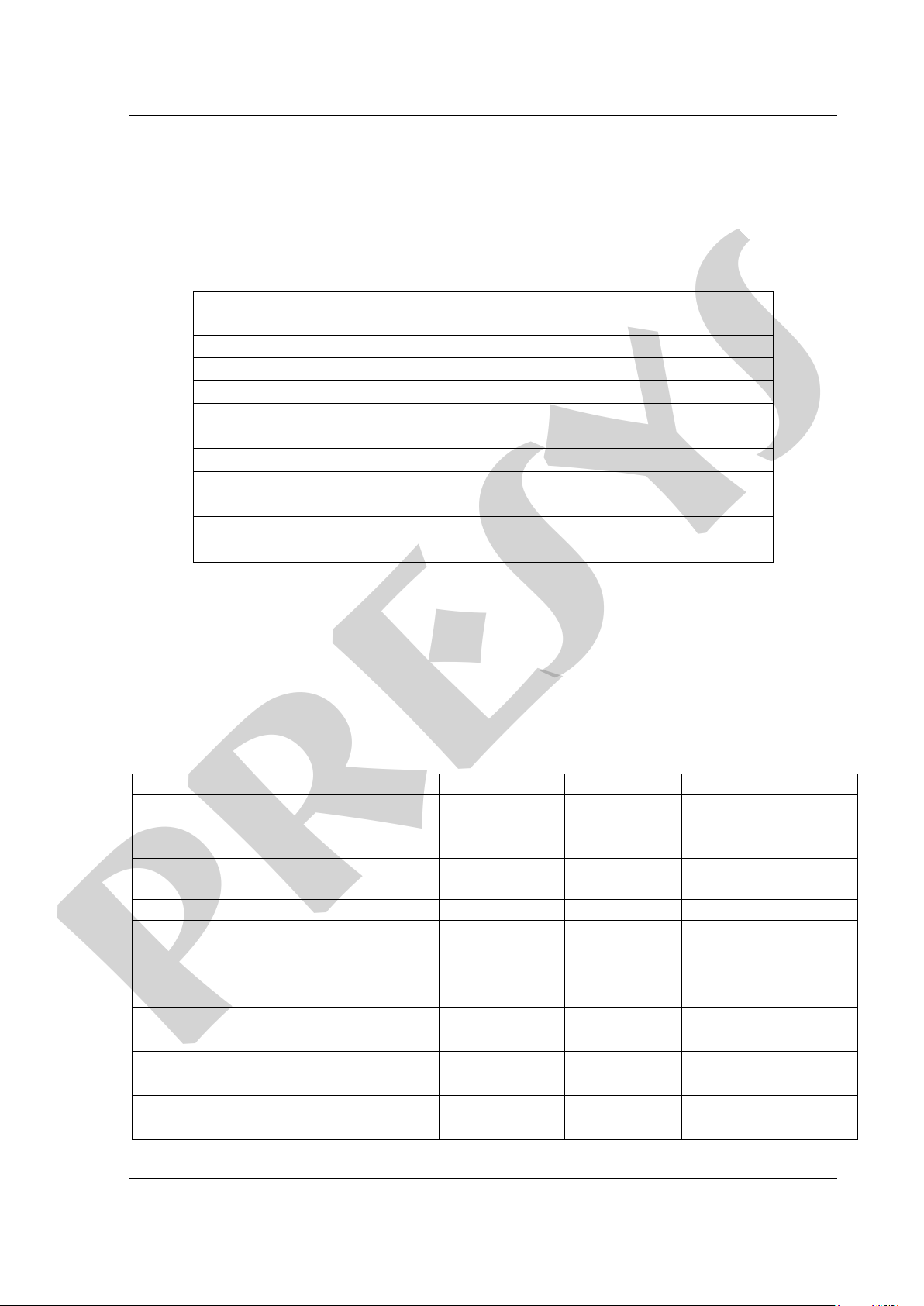
Ranges *
Resolution
Control
Stability
Accuracy
(0) 0 – 250 mmH2O
0.001
0.04 % FS**
0.025 % FS**
(1) 0 – 1 psi
0.0001
0.02 % FS
0.025 % FS
(2) 0 – 5 psi
0.0001
0.004 % FS
0.012 % FS
(3) 0 – 15 psi
0.0001
0.002 % FS
0.012 % FS
(4) 0 – 30 psi
0.0001
0.002 % FS
0.012 % FS
(5) 0 – 100 psi
0.001
0.002 % FS
0.012 % FS
(6) 0 – 250 psi
0.001
0.002 % FS
0.012 % FS
(7) 0 – 500 psi
0.01
0.004 % FS
0.012 % FS
(8) 0 – 1,000 psi
0.01
0.004 % FS
0.012 % FS
(9) 0 – 3,000 psi
0.01
0.004 % FS
0.012 % FS
Input Ranges
Resolution
Accuracy
Remarks
millivolt
-150 mV to 150 mV
0.001 mV
0.01 % FS*
R
input
> 10 M
auto-ranging
-500 mV to -150 mV
0.01 mV
0.02 % FS
150 mV to 2450 mV
0.01 mV
0.02 % FS
volt
-10 V to 11 V
11 V to 45 V
0.0001 V
0.0001 V
0.02 % FS
0.02 % FS
R
input
> 1 M
mA
-5 mA to 24.5 mA
0.0001 mA
0.02 % FS
R
input
< 120
resistance
0 to 400
400 to 2500
0.01
0.01
0.01 % FS
0.03 % FS
Excitation current
0.85 mA, auto-ranging
Pt-100
-200 to 850 C
-328 to 1562 F
0.01 C
0.01 F
0.1 C
0.2 F
IEC 60751
Pt-1000
-200 to 400 C
-328 to 752 F
0.1 C
0.1 F
0.1 C
0.2 F
IEC 60751
Cu-10
-200 to 260 C
-328 to 500 F
0.1 C
0.1 F
2.0 C
4.0 F
Minco 16-9
Ni-100
-60 to 250 C
-76 to 482 F
0.1 C
0.1 F
0.2 C
0.4 F
DIN-43760
presys
1.2. Technical Specifications
1.2.1. Pressure Control Module
Choose one range for the Pressure Control Module between 250 mmH2O and
3,000 psi.
(*) Gage pressure, vacuum (only for range 3), or compound (from range 3 to 8). Absolute pressure is obtained with the
optional barometric reference.
(**) FS = Full Scale.
Accuracy values are valid within one year and temperature range from 20 to 26 °C.
Outside these limits add 0.005 % FS / C, taking 23 °C as the reference temperature.
These values are obtained through algorithms of temperature compensation on pressure
measurements.
1.2.2. Auxiliary Input
(*) FS = Full Scale.
Page 2

PRESYS Instruments PCON-Y17
presys
Accuracy values are valid within one year and temperature range from 20 to 26 °C.
Outside these limits add 0.001 % FS / C, taking 23 °C as the reference temperature.
1.2.3. General Specifications
Power supply from 100 to 240 Vac, 50/60Hz.
Thirty minutes warm-up time.
Transmitter power supply (TPS): 24 Vdc, with protection from short circuit (30 mA).
Contact input for calibration of pressure switches.
Operating temperature range: 0 to 50 C.
Relative Humidity: 0 to 90 % RH.
Engineering units – psi, bar, mbar, MPa, kPa, Pa, atm, at, mmH2O, cmH2O, ftH2O,
inH2O, inH2O@60°F, torr, mmHg, cmHg, inHg, inHg@60°F, gf/cm2, kgf/cm2, kgf/m2 (see
section 4 – Pressure Units Conversion). Temperature: °C, °F, K, °R.
Built in Web Server,
Ethernet communication. USB port for software/firmware upgrade.
HART® Communication Protocol (optional).
Includes technical manual and test leads.
Calibration Certificate (optional).
Pneumatic Connection: 1/8” Female BSPP.
Overpressure: For the range of 3000 psi, up to 110% full scale of the pressure control
module. For the other ranges, up to 130% of the full scale of the pressure control
module.
Power Supply: 100 to 240 Vac 50/60Hz (Time Delay Type Fuse 1 A / 250 V / 5x20 mm).
Dimensions: 135 mm x 350 mm x 270 mm (HxWxD) - DT Version – Desktop.
132 mm x 483 mm x 255 mm (HxWxD) - RM Version – Rack Mounting.
Weight: 5.0 kg approx. (DT Version - Desktop)
9.5 kg approx. (RM Version – Rack Mounting)
One-year warranty.
Notes:
* Changes can be introduced in the instrument, altering specifications in this manual.
* HART® is a FieldComm Group trademark.
Page 3

PRESYS Instruments PCON-Y17
presys
1.3. Special Software Features
- PRESET POINTS: edit your most frequently used setpoints and access them quickly.
- STEP: steps or setpoints with configurable time.
- STABILITY/LEAK TEST: measures the variation of the signal (be it Pressure or an
Auxiliary Input signal) within a configurable period.
- PRESSURE SWITCH TEST: automatic testing of pressure switches.
- AUTOMATED TASKS: create calibration work orders and automatic execution of
calibration services, storage of data and generation of calibration report to a directly
connected USB printer or PDF file.
- DATA LOGGER: monitoring of input or output signals, storage and visualization of data
in chart or table.
- VIDEOS: storage and viewing videos on the calibrator screen.
- MEMORY MANAGER: stores configuration types predefined by the user.
Page 4
PRESYS Instruments PCON-Y17
presys
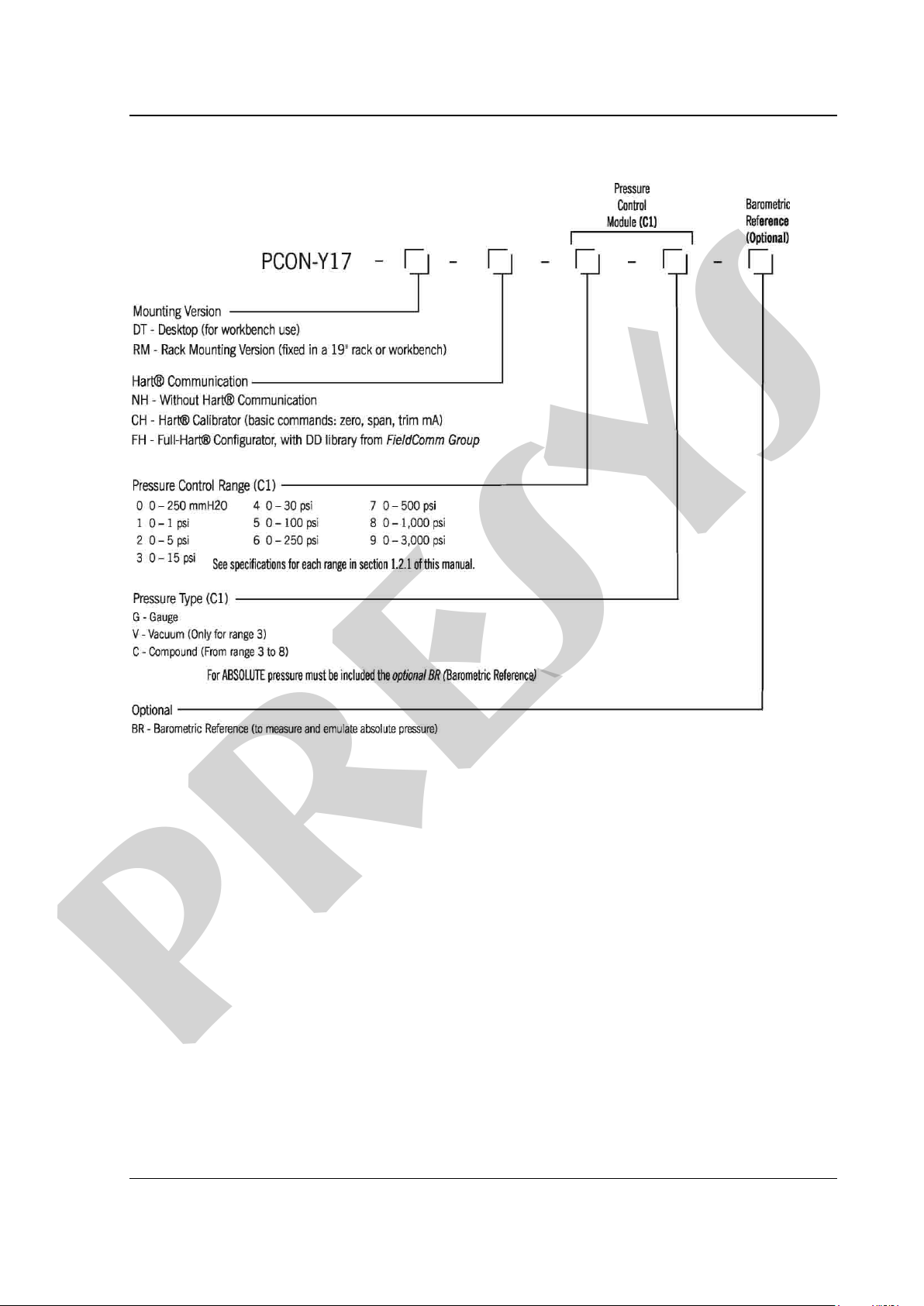
1.4. Order Code
Page 5
PRESYS Instruments PCON-Y17
presys
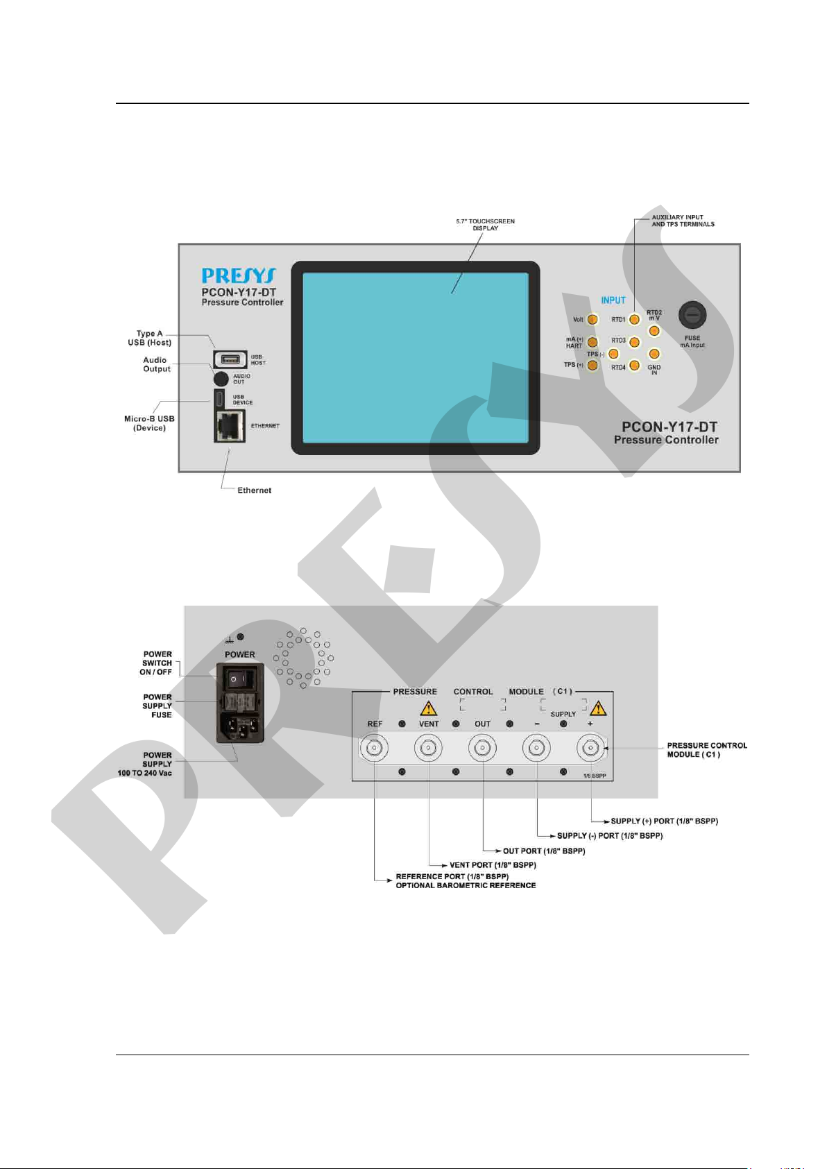
1.5. Parts Identification
DT Version - Desktop
Front Panel
Rear Panel
Fig. 01 - Front Panel
Fig. 02 - Rear Panel
Page 6
PRESYS Instruments PCON-Y17
WARNING!
During startup, do not connect any instrument to the output port of the
Before making connections to the Pressure
VENT operation.
presys
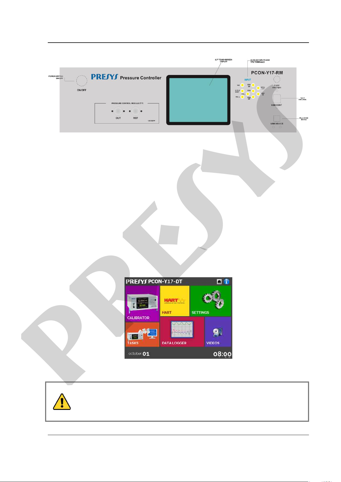
RM Version – Rack Mounting
Fig. 03 – Front Panel PCON-Y17-RM
Note:
For the 3000 psi Pressure Control r ange there is no VENT PORT.
On the PCON-Y17-RM, the VE NT and S UPPLY ports of the pressure control module
are located on the back of t he m odule, as well as the power supply (100 to 240 Vac ) and
Ethernet port.
2 - Calibrator Operation
Turn on the PCON-Y17 by pressing the power switch (located on the rear panel
for the DT version, and on the front panel for the RM version).
When powered on, the calibrator goes through a self-test routine. In case of
failure, it displays a message to indicate the error; if that occurs, please contact the
Presys Technical Assistance department.
After the self-test is completed, the display shows the main menu, as showed
below.
Fig. 04 - Main Menu
Pressure Control Module.
Control Module, enter the CALIBRATOR menu and wait for the automatic
The main menu is divided in the following functions:
Page 7

PRESYS Instruments PCON-Y17
presys
CALIBRATOR – selects the input/output functions (Pressure Control Module, Auxiliary
Input Signals and Pressure Measurement Module), see section 2.1.
HART® – optional module that allows communication with devices that have Hart®
Communication Protocol, see section 2.2.
TASKS – performs calibrations automatically, see section 2.3.
DATA LOGGER – record measurements, enabling visualization on chart or table, see
section 2.4.
VIDEOS – features videos made by Presys to assist in the use of the calibrator, and can
also store videos made by the user, see section 2.5.
SETTINGS – general instrument settings, see section 2.6.
2.1. Calibrator Menu
To select the Pressure Control Module and the Auxiliary Input functions press
the CALIBRATOR button from the main menu.
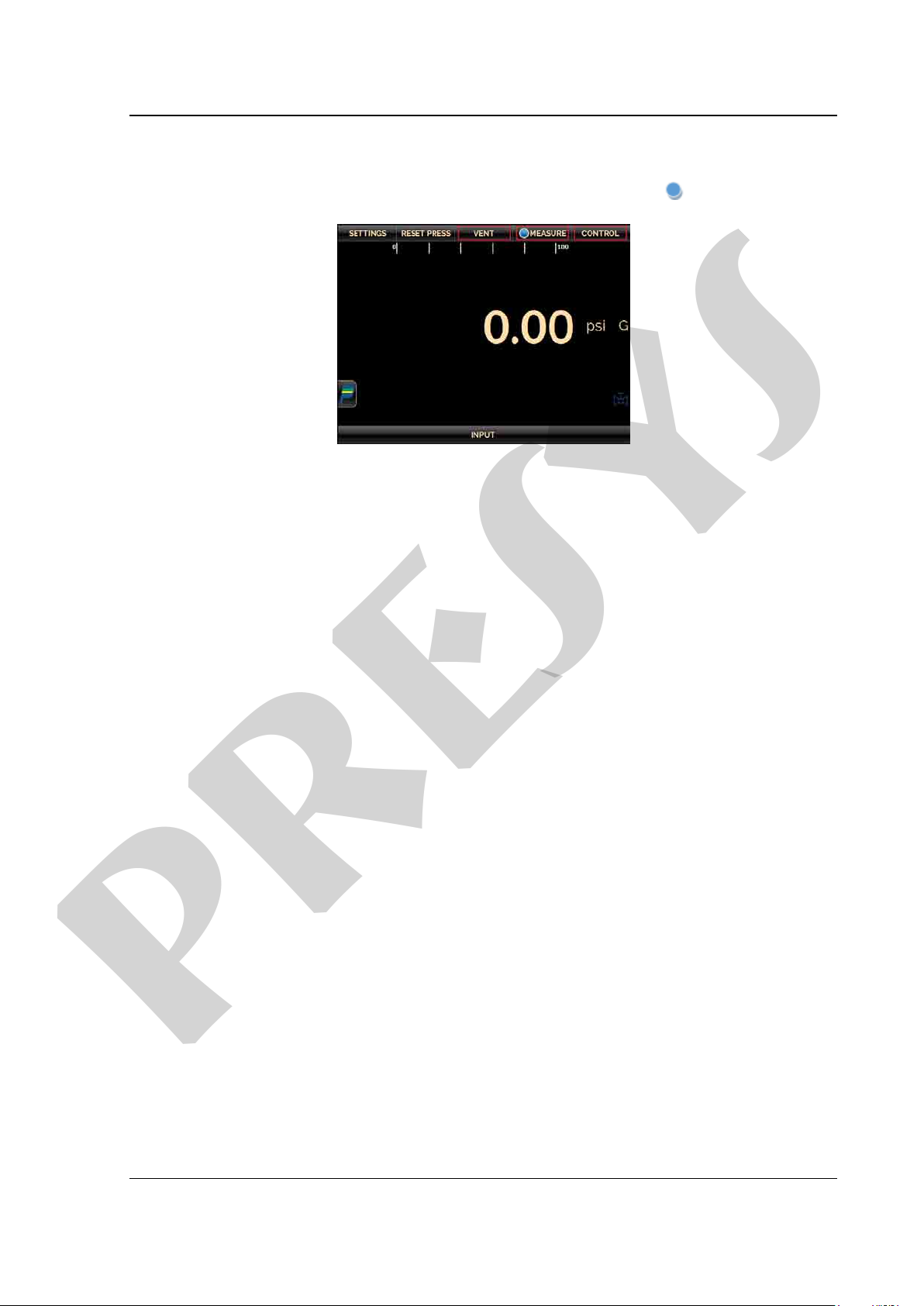
When first entering the CALIBRATOR menu, the PCON-Y17 executes a VENT
operation and an AUTO RESET of the pressure read in the Pressure Control Module.
When it is done, it goes to MEASURE mode and opens the output isolation valve (see
the module layout in section 2.1.2). The following screen is displayed.
Fig. 05 - Calibrator initialization
Page 8
PRESYS Instruments PCON-Y17
presys
The Pressure Control Module has three operation modes: MEASURE, VENT and
CONTROL (see sections 2.1.2, 2.1.3 and 2.1.4). To select an operation mode, press one
of the buttons indicated below. The current state is indicated by the symbol.
Fig. 06 - Pressure Control Module - Operation Modes
2.1.1. Pressure Control Module – Connections
PCON-Y17-DT controls the pressure in the output port with high precision and
stability. To control the pressure, a pressure between 110% and 130% of the full range of
the control range is applied to the SUPPLY (+) power port, except for the 3,000 psi range
which has a reduced range of 104% to 110% of the full scale. The pressure supply must
be pneumatic, dry and clean air, nitrogen or inert gases.
If it is not possible to supply the PCON-Y17 with a pressure between 110% and
130% of the full range of the control range (and between 104% and 110% FS for the
range of 3,000 psi), a lower supply pressure may be used, but the instrument control
range will also be reduced. The PCON-Y17 measures the supply pressure and
automatically sets its control parameters for better performance. If the pressure is not
sufficient, a warning is displayed on the screen.
The presence of water, oil or particles in the pressure control module can cause
irreparable damage to the system. Equipment and connections must be clean and dry
when connected to both pressure supply and output. The use of impurities filters is
necessary to protect the system. The use of 10 micron (m) filters is recommended.
Page 9

PRESYS Instruments PCON-Y17
presys
- For the DT version, all pneumatic connections are located on the rear panel of the PCON-Y17-DT.
- For the RM version, the pneumatic connections VENT, SUPPLY (+) and SUPPLY (-) are located on the
rear panel, pneumatic connections OUT and REF are located on the front panel of the PCON-Y17-RM.
Fig. 07 - Pressure Control Module
If you do not need to control negative pressure, connect to the supply (-) port a
muffling device to reduce the sound levels.
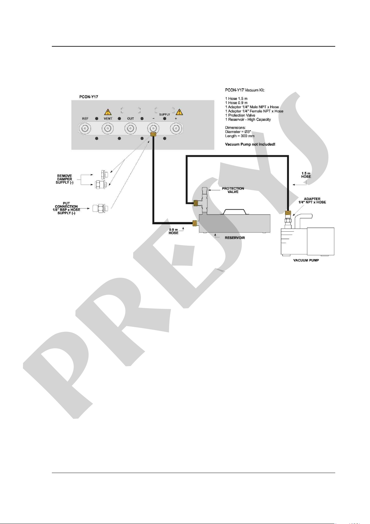
To use the PCON-Y17 with negative supply (vacuum), remove the damper (air
diffuser) from the SUPPLY (-) port and connect the PCON-Y17 vacuum kit and the
vacuum pump (see Fig. 08). The negative supply does not need to be regulated. It is
recommended that the vacuum pump has less than 70 mbar absolute (-13.5 psig)
output.
When installing a vacuum feed, the pump must be protected against positive
pressure discharge by the controller, which may damage and/or reduce the performance
of the vacuum pump. This occurs in set point changes since the PCON-Y17 releases
positive pressure from the system to the atmosphere through the SUPPLY (-) port.
Page 10
PRESYS Instruments PCON-Y17
presys
The reservoir volume of the vacuum kit slows down and attenuates any sudden
increase in positive pressure, thereby protecting the output of the vacuum pump.
Fig. 08 – Connections for Vacuum
Precautions must be taken to prevent the transfer of oil from the vacuum pump to
the PCON-Y17. Before turning off the vacuum pump supply, it is recommended to
disconnect the hose that connects the vacuum pump to the reservoir, allowing
atmospheric pressure to enter directly into the pump and not through the instrument.
Without this procedure, the oil present in the vacuum pump can progressively rise to the
PCON-Y17 through the hose.
Page 11
PRESYS Instruments PCON-Y17
WARNING!
The instruments described in this technical manual are equipments for
use in specialized technical area. The user is responsible for the
configuration and selection of values of the parameters of the
the instrument. Use the instrument only according to this technical
WARNING!
Do not apply pressure above 130% of full scale of the control range (for
the range of 3000 psi, do not apply pressure above 110% of full scale
WARNING!
Be careful with the pressure connections. High pressures with a large
inert gases
WARNING!
When a vacuum pump is attached to the negative supply port of the
the negative
WARNING!
Other pressure equipments and accessories (such as hose, reservoirs,
presys
instruments. The manufacturer warns against the risk of incidents with
injuries to both persons and p roperty, resulting from the incorrect use of
manual. Any operation not described here is not allowed.
control range).
volume can cause damage to both persons and property.
Apply to the positive supply port pressure between 110% and 130% of
the full scale of the control m odule (for the 3000 psi range, the p ositive
pressure supply should be between 104% and 110%).
The pressure supply must be pneumatic, dry and clean air, nitrogen or
pressure control module, it is strongly recommended to use a protection
valve to atmosphere in the vacuum pump. When controlling from a high
pressure to a low pressure the gas is exhausted through
supply port and can cause damage to the vacuum pump. Before going to
a low pressure, it is recommended to make a VENT operation.
protection devices) connected to the calibrator mu st be a pprop riate to th e
working pressure.
Page 12
PRESYS Instruments PCON-Y17
WARNING!
The calibrator discharges gas to the atmosphere through the supply (-)
WARNING!
Before connecting the instrument under test to the output port, make a
inside the controller and go to
IMPORTANT!
All pressure equipment and accessories (such as hoses, connections,
nd out
presys
and vent ports. Leave these ports free.
The calibrator may produce high soun d levels when discharging gas. Use
a muffling device at the vent port.
VENT operation to discharge any gas
MEASURE mode. Before turning the calibrator off, it is recommended to
vent the gas inside the controller.
adapters, etc.) connected to the calibrator must be clean, free of residues
such as oil, dirt, dust etc. These residues can cause irreversible damage
to the internal system of the pressure control module. It is mandatory to
use filters in both the pressure feed (SUPPLY (+)/ SUPPLY(-)) a
(OUT).
Page 13
PRESYS Instruments PCON-Y17
presys
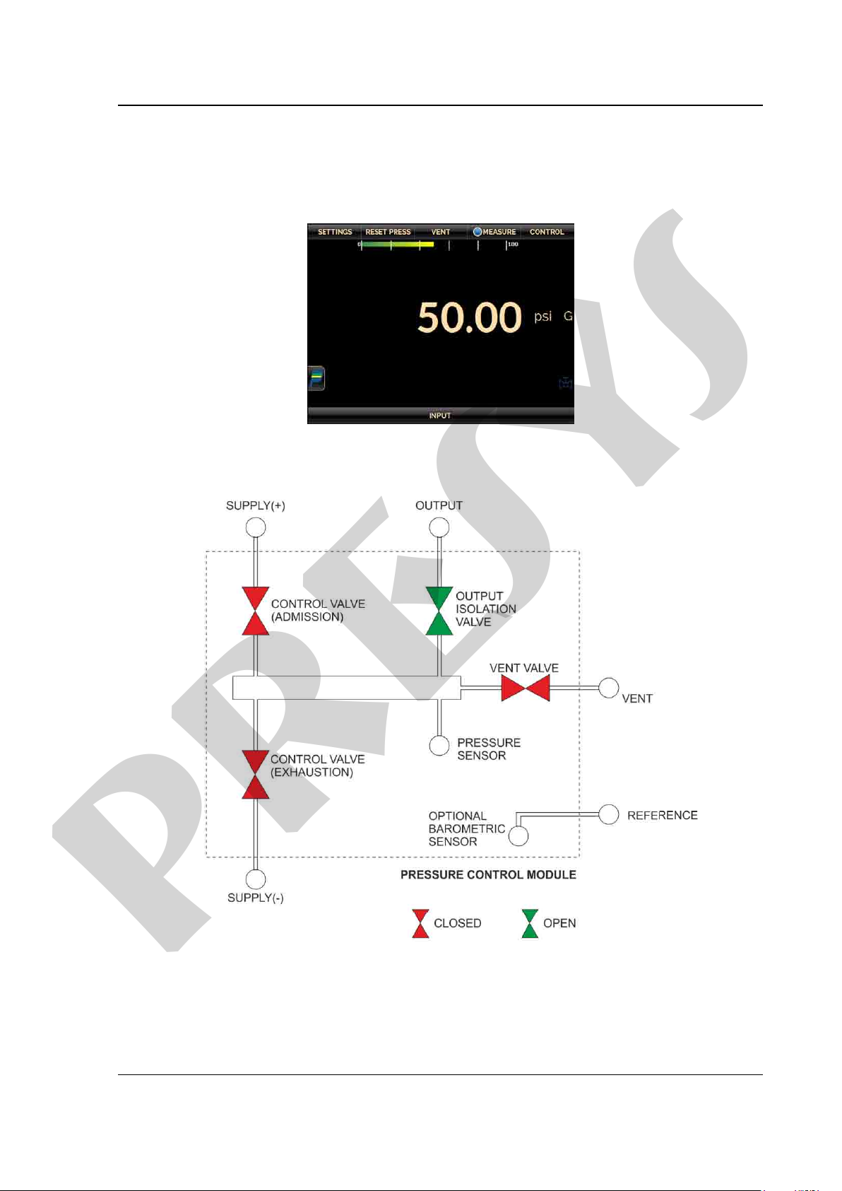
2.1.2. Measure Mode
In Measure mode, the calibrat or shows the pressure measurem ent in the Control
Module. In this state, the control mode is disabled.
Fig. 09 - Measure mode – screen
Note: The pressure controller of 3000 psi range does not have the output isolation valves (module connection to
the outlet is always open) or VENT (no VENT port to the atmosphere).
Fig. 10 - Measure mode – state of the valves
Page 14
PRESYS Instruments PCON-Y17
presys
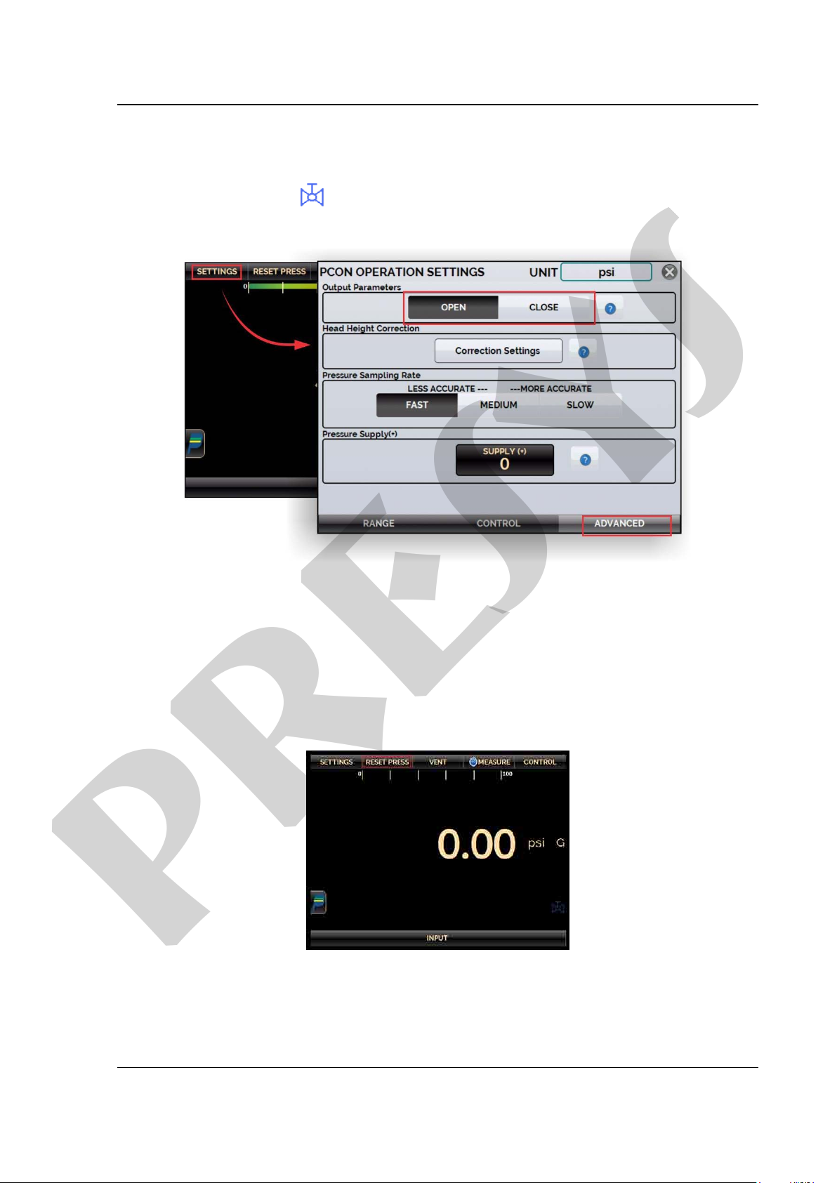
The state of the output isolation valve is user confi gurable. To change the state of
the valve, press the SETTINGS button shown below and change the Output Parameters
( OPEN / CLOSED) in the ADVANCED tab.
The valve symbol
valve is OPEN. This valve is used to isolate the unit under test f rom t he pressure control
module.
NOTE: It is not possible to close the output isolation v alve or to maintain it closed if the
pressure inside the control module is larger than the pres sure outside t he control module
by 100 psi or more. The 3000 psi pressure control range does not have an outlet
isolation valve.
To zero the current pressure measurement, press the RESET PRESS button.
appears on the calibrator scr een indicat ing that the I solation
Fig. 11 - Output Isolation Valve Status
Fig. 12 - Reset of the current pressure measurement
Page 15
 Loading...