

Preston Cinema Systems FI+Z, MDR-3 User Manual
F I + Z Lens Control
Rev 5.2

Preston Cinema Systems
1659 Eleventh Street
Santa Monica, CA 90404
Table of Contents
I. Introduction p-3
A. System
B. Hand Unit 3
C. Micro Force Zoom
D. Remote Iris Box
E. Optional Wireless Units
F. MDR3
G. DM-1X, DM-2, DM4 motors
H. DXL Module
II. FI+Z Basic Operation Summary p-4
A. Motor Driver and Digital Motor set-up
B. Hand Unit 3
III. Hand Unit Detailed Description p-8
A. Hand Grip p-8
1. Configurations
2. Changing the hand grip
B. HU3 Set-Up and Operation p-9
1. Main Display p-9
2. Menu Screen
3. Radio Channel Selection
4. Lens Set-Up p-9
5. Operating Mode p-12
6. System Menu p-13
7. Zoom Bargraph p-14
8. Lens Limits
9. Panatape and Cinetape. p-15
11. Light Ranger 2 p-15
10. Software Updates p-16
13. Remote Iris Unit
14. Focus Ring Light/Dimming
IV.
MDR3 Detailed Description p-17
V.
Digital Motors p-20
A. Digital Motor Brackets p-21
2

VI. MDR3 Brackets
VII.
Battery Packs and Charger p-22
VIII. Technical Information p-23
A. FCC Statement
B. Connector Pin-Outs p-24
1. Hand Unit
2. MDR3
C. MDR3 Camera Cable list p-24
D. Transmitter Channels and Frequencies p-25
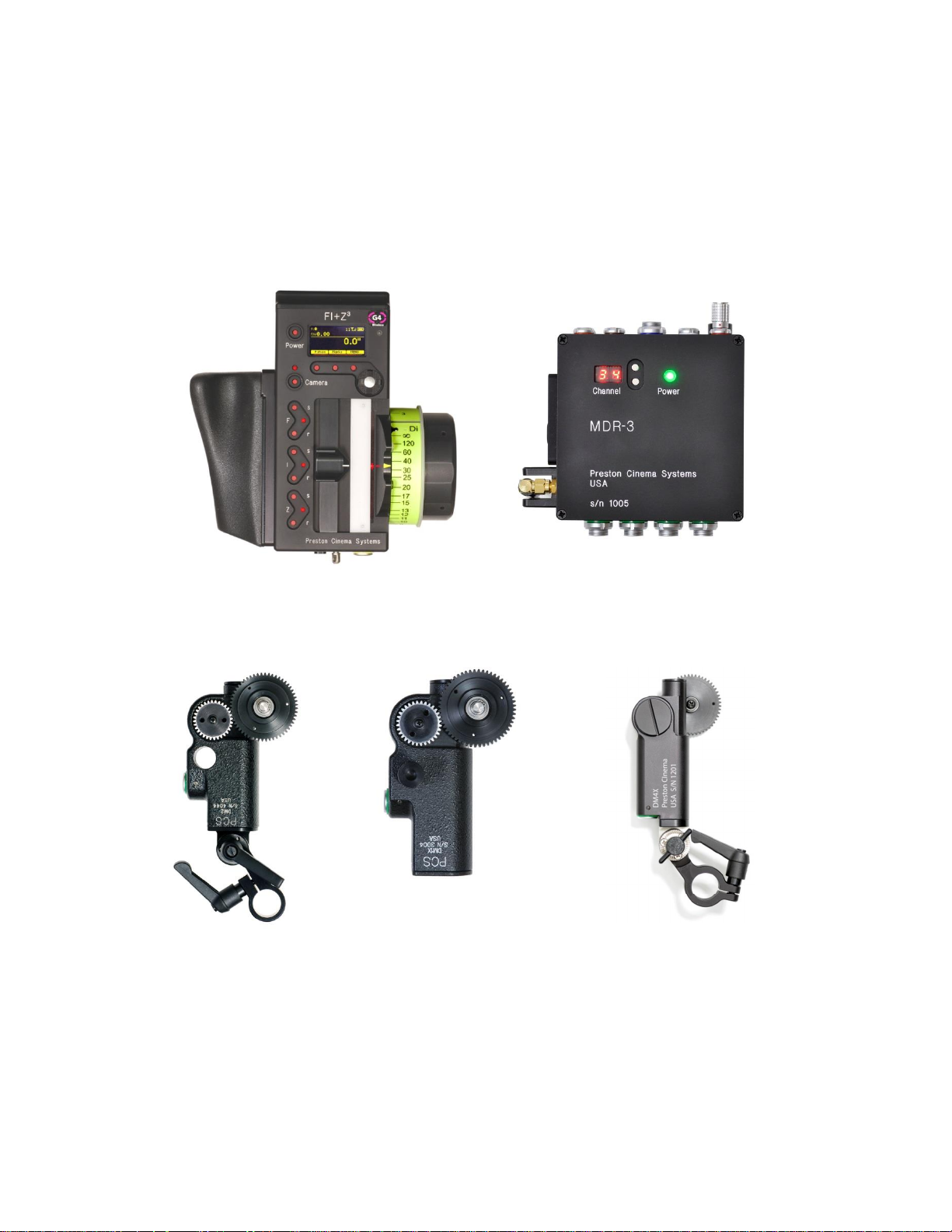
I. Introduction
A. System. The FI+Z system controls the complete array of lens and camera functions.
It consists of the Hand Unit HU3, one or more Motor Drivers, a set of Digital Motors, a
Micro Force zoom control, and a variety of optional controls including wireless Focus/Iris,
Zoom, and the Light Ranger 2 focus assist.
B. The HU3 gives focus pullers not only a robust and reliable unit but one whose
ergonomics allow the focus puller to accurately translate the changes in actors’ positions
on set to a precise movement of the focus knob.
Careful attention has been paid to protecting the unit from impact and environmental
damage. The microwave antenna is integrated within a form fitting cover. The iris slider
uses a magnetic sensor to eliminate the opening required for a conventional sliding seal.
The soft urethane handgrip and focus knob cover not only provide for comfortable all day
operation, but also protect the unit from shock.
Generation 4 (G4) transceivers address the challenges brought about by the proliferation of
wireless devices using the 2.4 GHz wireless band. Their new architecture results in a greatly
improved ability to reject interference from other devices operating in the same band as
well as out of band interference. The improvement in performance is quite significant,
typically 10x or better interference rejection than previous transceivers.
The HU3 and MDR3 can also be connected through a cable link using the command cable.
This provides high reliability communication over long distances (1km).
To address the metadata requirements of CGI, the MDR3 has motor position and camera
data available at the serial port for incorporation into a metadata stream.
Lens Mapping software matches the focus distance marks of a lens to the pre-printed
focus marking rings. Five focus rings, labeled A – E, cover focus distances from 9" (.35m)
to 6' (2m). The set of focus rings have large, easy to read, distance marks printed on a
3

bright fluorescent background for excellent visibility under all lighting conditions. The
rings are automatically illuminated in low light conditions by a pair of white LED's.
Once a lens is calibrated, it can immediately be used with any of the focus rings. The onboard lens library holds data for 255 lenses. Calibration for a lens change only requires
the few seconds needed to choose the lens from the library.
A bright, sharp, OLED display shows camera, lens, and hand unit set-up status. Focus
distance settings can be displayed digitally for Cooke i-Lenses, or any lens which has been
calibrated to the unit. Data from compatible ultrasonic measuring devices (Panatape,
Cinetape) can be displayed.
The bright zoom bargraph display shows both the zoom lens position as well as user-set
end limits. End limits are set with Set/ Reset tactile switches arranged in three groups. An
LED in each group indicates when limits are active.
C. The zoom function is implemented by a Micro Force control. It can be directly
connected to the Hand Unit using a bracket or operated remotely using a cable. The
camera may be started either from the Micro Force or from the Hand Unit.
D. The Remote Iris Box provides a separate control for the Iris function. It is automatically
enabled when plugged into the Iris accessory connector on the Hand Unit.
E. Optional wireless units allow various lens and camera control functions to be split off
from the Hand Unit functions. The Focus-Iris unit is a single channel hand control. When
active, it takes over either the focus or iris function from the Hand Unit. The Radio Micro
Force module allows the zoom function to be split off from the Hand Unit. The Light Ranger
2 is a high-precision focus assist which generates a graphics overlay indicating the
direction and amount the focus knob must be turned to bring a subject into focus.
F. The Motor Driver (MDR3) supports 4 motor channels and camera run/stop. The 30
channel transceiver allows the simultaneous operation of both the Hand Unit 3 as well as
the optional wireless hand units listed previously. An integral voltage booster allows for
operation over a voltage range of 11 – 28 VDC. Switches are provided for adjusting Motor
Torque and reversing direction.
G. DM1X, DM2, and DM5 digital motors cover drive requirements from the largest zoom
lenses to small prime lenses. They have proven their toughness under extremes of
temperature, humidity and vibration. All of them use hardened metal gears with super-hard
coatings to give very low backlash over thousands of hours of operation.
H. The DXL Module is a wireless 3-channel motor driver for the Panavision DXL camera.
II. FI+Z Basic Operation Summary
.
4

Main
Display Screen
Lens Selection
Focus Ring Letter
Host MDR
A. Set-up the Motor driver (MDR3) and Digital Motors.
a. Slide the motor brackets onto the matte box support rods. Position the motors and
brackets so that the motor gears mesh with the corresponding lens gears. Couple
the lens motors to the lens gears. Adjust the motor positions relative to the lens to
have minimum backlash and tighten the handles of the motor brackets. Do not
couple the motor to the lens too tightly or binding will result. Check that the motor
brackets do not flex or slip on the matte box support rods. For normal lenses, the
Torque adjustment switches can be set in the middle position of their range.
Connect the motor cables from the motors to the MDR3.
b. Use the designated camera cable to connect the MDR3 to the camera accessory
receptacle. (See pages 24, 25 for the cable list). Connect the power cable from the
MDR3 to the camera or battery power receptacle. Important: check that camera is
capable of supplying sufficient current for the MDR3. This information is usually
provided the camera manufacturer in their specifications. A conservative estimate of
the maximum MDR3 current requirement is 1A per motor at 24VDC or 2A/motor at
12VDC.
c. Apply power to the MDR3. Press the reset button. The motors will calibrate
themselves to the mechanical span of the lens rings.
d. Select the MDR wireless channel with the channel selection switches either on the
top cover or the side channel display.
B. HU3 Set-up
a. Install the FM500 battery.
b. Press the Power Switch momentarily. The main display screen will appear.
Radio Channel
Signal Strength bars
Battery Charge
Shows focus distance
in digital format
(Lens must be calibrated)
All functions are accessed through
the Menu key
5

To turn off the power to the unit, press the Power Switch for 3 seconds.
Menu Screen: Channel Selection
c. If MDR3 appears in the upper right corner of the display, the HU3 and MDR3 are
both set to the same wireless channel. If the wireless channels of the HU3 and MDR3
do not match, the message No Host! will appear in the upper left corner of the
display.
d. Match the HU3 wireless channel to the MDR3:
· Press the Menu soft key. “Channel” will be highlighted. Use the Nav key to move
the selection to the right. Change the channel number with the Nav key to match
the setting of the MDR3.
· The Signal Strength bars will appear. To return to the main menu, press the Nav
key left.
e. To use a blank focus marking ring, turn off the Focus mapping:
§ Press the Menu key.
§ Select Lens.
§ If the focal length and serial number of a lens appears to the right of “Lens”,
press Fmap OFF.
§ The HU3 is now ready for basic operation. The blank focus marking ring,
and iris marking strip can be used to manually mark lens calibrations.
f. Focus mapping eliminates the need to manually mark separate rings for each lens.
Data from the lens library is matched to pre-printed focus marking rings. This
makes process of lens changing quick and efficient. A detailed description of this
function showing the display screens is given in section III. To load focus data for a
lens and select a focus ring:
· Press the Menu key.
· Use the Nav key to select Lens.
6

Microwave Antenna Cover Ambient Light Sensor
OLED Display
3 x Soft Keys
Splash Resistant
Housing
Hand Unit Power
Camera R/S with LED
Molded Hand Grip
Iris Slider
senses through
housing wall.
Set/Reset switches
for Focus, Iris and
Zoom
· Press Choose.
· Select the lens location (All lenses, My List A…..)
· Select the lens and press OK or the Enter key (the center of the Nav key).
· Set the lens to infinity (as directed) and Enter/Next.
· Press Ring and choose a focus ring with the desired near focus.
· Install the same focus ring on the focus knob.
4-way Navigation “Nav” Key
& Enter key (in center).
Pre-printed Focus
Marking Ring
Zoom Bargraph
Battery
Release
Neck Strap
Attachment point
LEMO receptacle for
Remote Iris
Hand Unit 3 Functions
Focus Knob with soft
Urethane Knob Grip
White LED’s (2) for
focus marking
ring. Brightness
adjusted with the
7
and Quick Release Plate
and bracket 4336
III. Hand Unit 3
. Detailed Description
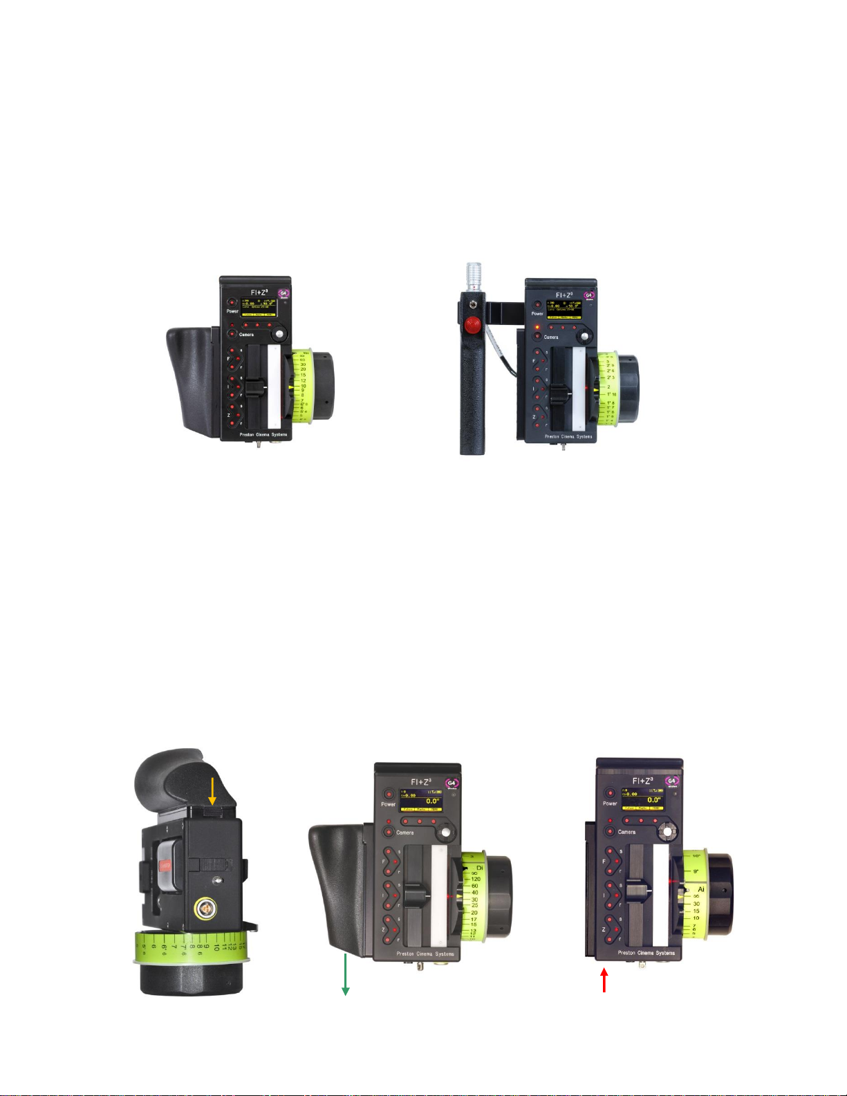
A. Grip Configurations
1. The Hand Unit can be set-up with a molded Hand Grip for Focus and Iris control or with
the Hand Grip replaced by a flat cover to accommodate a bracket and Micro Force zoom
control.
.
HU3 with Hand Grip
HU3 with Micro Force
2. Removing the Hand Grip. The Handgrip is removed to allow the bracket for the Micro
Force to be installed.
· Press the Grip Release toward the HU3 housing (1).
· Slide the Grip downward (2)
· Replace the Grip with the cover (3).
· Install the Micro Force bracket using the threaded hole at the rear of the
HU3.
(1)
(2)
(3)
8
 Loading...