

Page 1

Maintenance Manual
[email protected] • www.prestonability.com
Tel NL 036 53 53 580 • Tel BE 014 75 73 40
Page 2

Contents
1. Safety instructions 3
2. Specific Tools for technicians 4
3. Specific Parts: 4
4. Options / Accessories assembling : 5
5. Mechanical Adjustments 6
6. Front Electronics Board Setup 8
7. Controller Programming / Setup 9
8. Periodic maintenance Check 14
9. Mechanical Fault troubleshooting 16
10. Control and Electronics system fault troubleshooting 18
10.1 General control system and Front Board Troubleshoots 18
10.2 Controller Troubleshoots 19
11. Mechanical assembly drawings 22
13. General Wiring diagram 23
Page 3

1. Safety instructions
1.1 General:
1.1.1 Technicians who are servicing the scooter should be authorized to service the
scooter.
1.1.2 Technicians who are servicing the scooter should be aware and follow all safety
instructions within the User Manual.
1.1.3 Technician should follow general safety instruction like using gloves, safety glasses
when needed.
1.1.4 The scooter weight with batteries is about 100 kg even lifting 1 wheel is about 30
kg. Always use other people help or a appropriate lifting device.
1.1.5 When lifting always use your legs and not your back.
1.1.6 The battery weight is about 14 kg . The power unit weight is about 15 kg. The seat
weight is about 15kg.
1.1.7 Never do any change in the product before consulting the manufacturer
engineering. Remember the products are approve as they are , any change
remove the manufacturer responsibility for the safety of the product.
1.2 Drive :
1.2.1 Technicians who are driving the scooter should be aware and follow all safety
instructions within the User Manual.
1.3 Mechanic :
1.3.1 It is possible that a technician will need to operate the scooter when he is standing
on the side ,working on different assemblies.
1.3.2 When no electric power and operation needed , always Stop the power by Switch
OFF and disconnecting the battery terminals.
1.3.3 Never put any part of your body under the scooter parts.
1.3.4 If necessary, first place a wood block under, to make sure no injure will happen.
1.3.5 Use standard tools. Use them according to their safety instructions .
1.4 Electric :
1.4.1 If necessary to operate the scooter when you are not seating on it. In such cases
you should be aware to the parts that can move by power – Power unit shafts and
wheels.
1.4.2 Never put your hands close to a part that is moving or turning. Be aware that your
cloth will not be trapped into one of the moving parts.
1.4.3 Batteries contain a large electric energy inside. This energy can cause sparks and
heat metals when short circuiting.
1.4.4 When working on the battery terminals, make sure no to short circuit between any
2 terminals. This can cause strong spars and make the tools very hot.
1.4.5 When working on the batteries, use protecting gloves and safety glasses.
1.4.6 Battery contains acid. Never open any of the battery case. If you see any liquid or
Gel aside, beware of it. It might be Acid.
Page 4

2. Specific Tools for technicians
Standard tool box (wrenches, socket-head cap screw , hexagon keys, Phillips
(crosshead) tip and/or screwdrivers, etc.)
Voltmeter (To measure 24VDC)
Air pressure gauge (To measure 35 psi)
Batteries tester (under load)
Density meter
Valve Wrench
Wooden blocks to elevate the Breeze during checks, maintenance and repairs:
2 blocks 20-22 centimeters height to place beneath the batteries box.
2 blocks 14-16 centimeters height to place beneath the foot rest area.
Remark : Always before operating a lifted Breeze make sure that the 2 rear
wheels are free to turn , so that the scooters will not move.
3. Specific Parts:
We recommend the availability of the following set of test and repair assemblies:
1. Front Board
2. Main Harnesses Cable.
3. Main Lights Harness Cable.
4. Main Supply Harnesses.
5. Controller SDrive 120A - P&G
6. Motor/Power Unit
7. Also it is very much recommended hold and use P&G SP-1 Programmer (for S-Drive,
possible to upgrade old model to modified free of charge).
Page 5

4. Options / Accessories assembling :
Most accessories based on the rear square pipe :
The accessories are :
4.1 Rear Basket 4.2 Seat safety belt. 4.3 Walker Holder
4.4 Cane Clip Attachment. 4.5 Single Cane Holder 4.6 Double Cane Holder
Page 6
5. Mechanical Adjustments
#
Description
Where
How to Adjust
1
Seat Height
Seat pin under the battery
cover.
See attached assembling
drawing:
Release both secure bolt and
level bolt. Change pin Level
hole as required . Rescuer
both level bolt and secure bolt.
Adjustments : 3 x 20 mm.
Arm rest
Page 7
Adjust the width .
Adjust the angle .
Front lights
Release the screw and adjust
The angle of the front lights.
Page 8
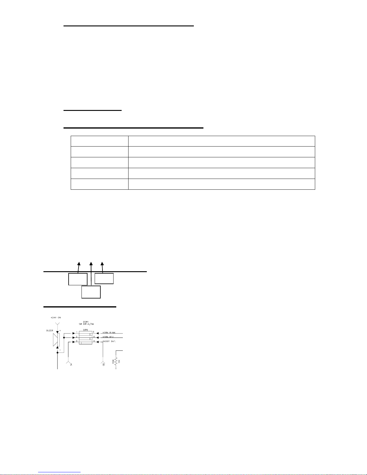
6. Front Electronics Board Setup
The Horns can be setup to work in one of the follows options :
Controller alarms, Tiller push button , Reverse alarm , Blinkers
alarms.
The front board include setup options for the Horn. This can be
done with the dipswitch DSW1 that is on the front board.
Deep switch : User Modes setup with relate to user needs.
Dip Switches Setup is as follows : (Shown the Default Set Up)
State
Description
"1" = Off
Horn while blinker or hazard are on .
"2" = On
Horn while derive backward
"3" = Off
When the battery too low – the scooter stop.
"4" =
No use.
Diagram sketch :
"1"
"2"
"3"
Page 9

7. Controller Programming / Setup
If the user cannot find a position on the half speed limit switch
control that suits him, the controller can be programmed to meet
his needs. The controller can be programmed in two ways – with
an SP1 Programmer or specialist PC software and interface
cable.
The SP1 is a small hand-held unit which can be plugged into
your controller to alter the program or into the charger socket .
The PC Programmer is a piece of PC software and an interface
cable. When the software is installed onto a PC, it can then be
connected to the controller by using the special interface cable.
The controller can then be programmed using a windows type
environment
The programming tools may be included with your scooter. If
they are not, the scooter distributor or service agent or scooter
manufacturer will are able to program the controller.
If you have a programmer, read the user guide before you use it.
If you re-program your controller, make sure that you observe
any restrictions given in your scooter user manual. Note any
changes you make for future reference.
Programming should only be conducted by healthcare
professionals with in-depth knowledge of PGDT electronic
controllers. Incorrect programming could result in an unsafe
set-up of a scooter for a user. PGDT accept no liability for
losses of any kind if the programming of the controller is
altered from factory pre-set values.
Page 10

7.1 Controller Parameter List and programming with hand
programmer SP1 :
BREEZE C
PROGRAMER SET-UP .
Programming version list : 8.0.16. 22/07/10
The list of parameters fit to power-units 950W-12km/h,10km/h and 15km/h.
The parameters refer to "S-Drive 120" controller with hand programmer "SP1"
To program through the "Charge Socket" use the adaptor.
Programmer SP1
Adaptor to the Charger Socket
Instructions to change the parameters :
1. Connect the adaptor to the programmer and connect to the "Charge Socket" –
the programmer will start working.
2. The up / down arrows let you choose the parameters.
3. In order to change a parameter – stand on the parameter press "enter" the
values will then appear in the display window.
4. With the help of the arrows you can change the values.
5. After changing the value push enter the scooter will beep – turn key switch off
and then on.
6. The programmer will display the next parameter. To make further changes
repeat step # 5
7. Press enter again to return to the parameter menu
8. When you get to the "Engineer Menu" press enter to get to the sub-menu
How to improve and to adjust parameters to the customer :
1. Change the accelerate of the scooter , forward .--- Line 1 .
2. Change the decelerate of the scooter , forward .--- Line 2
3. Change the accelerate of the scooter , reverse .--- Line 3.
4. Change the decelerate of the scooter , reverse .--- Line 4.
5. Change the max. speed - forward .--- Line 5 .
6. Change the max. speed – reverse .--- Line 7.
7. Change the direction of travel of the Wig-Wag. Invert Throttle --- Line 9 .
8. The time to enter to sleep mode when the key switch is "On" . Sleep
Timer . Line 10 .
9. Reads the number of faults and how many times they occurred. Read
System Log . Read System Log . Line 11 .
10. Working time of the scooter.Real timer . Line 12 .
11. Decelerate – soft stop.Line . 20 , 24 .
Page 11
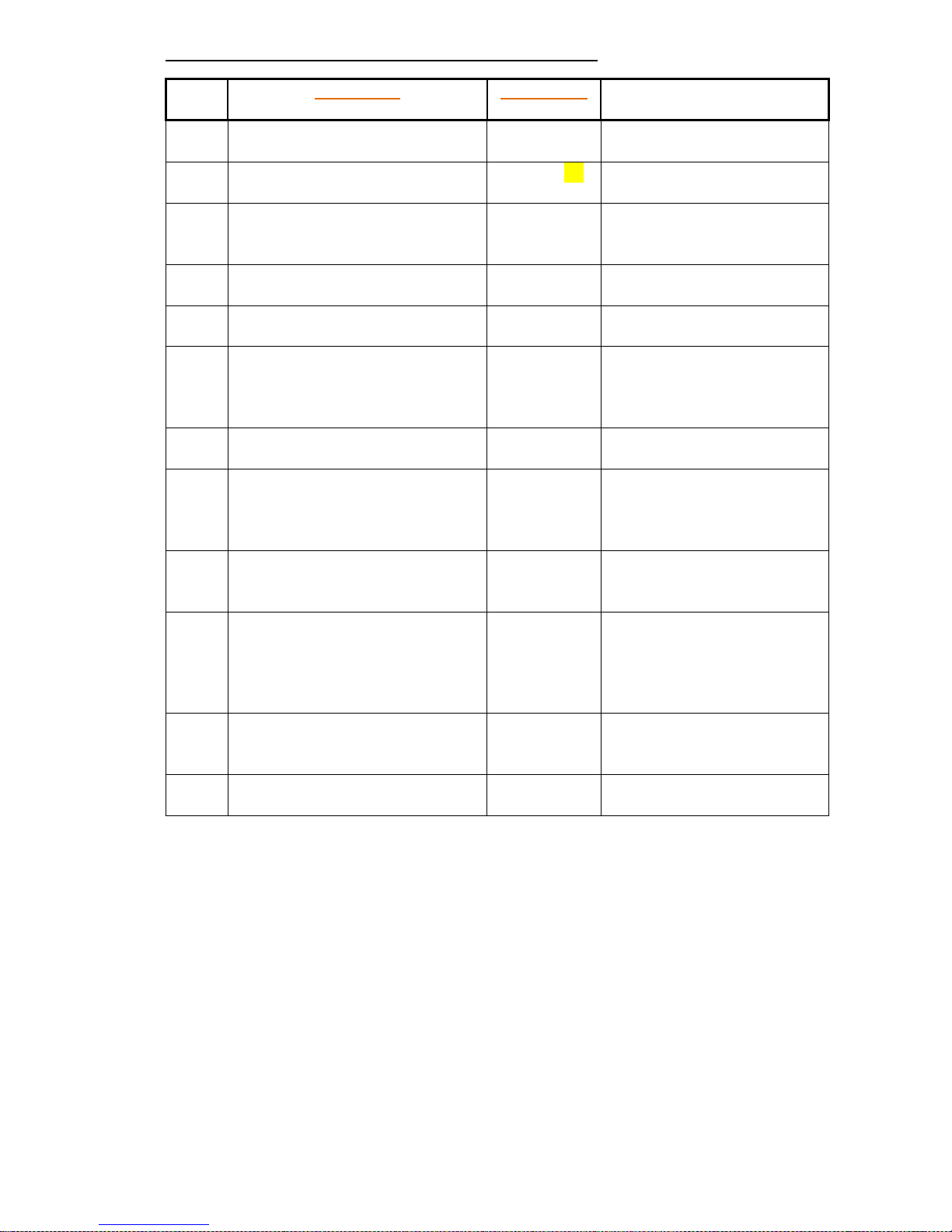
The list of parameters for power-unit 950W-12km/h :
Comments
SETTINGS
Parameter
The time for acceleration
forward.
FAST: 40
Slow: 40
Forward Acceleration Profile
1
Parameter to change the
stopping distance-FF.
FAST: 15
Slow: 15
Forward Decel'n?
2
The time for acceleration
– Reverse .
FAST: 40
Slow: 40
Reverse Accel'n
3
Parameter to change the
stopping distance-Rev.
Fast : 20
Slow : 20
Reverse Deceln ?
4
Parameter to lower the
maximum forward speed
Fast: 100
Slow: 100
Max Forward Speed?
5
Parameter to lower the
minimum speed forward.
(minimum speed on the
potentiometer)
Fast: 50
Slow: 50
Min Forward Speed?
6
Parameter to lower the
maximum reverse speed
Fast: 50
Slow: 50
Max Reverse Speed ?
7
Parameter to lower the
minimum speed reverse.
(minimum speed on the
potentiometer)
Fast: 25
Slow: 25
Min Reverse Speed ?
8
Change the direction of
travel of the Wig-Wag
(standard NO)
No/Yes Invert Throttle?
9
The time to enter to
sleep mode when the key
switch is "On" .
"0" – the function
doesn’t work .
0 m
Sleep Timer?(Minute)
11
Reads the number of
faults and how many
times they occurred
1 E09, #144
Read System Log
11
Working time of the
scooter.
Elapsed:
110 H
Real Timer :
12
Page 12
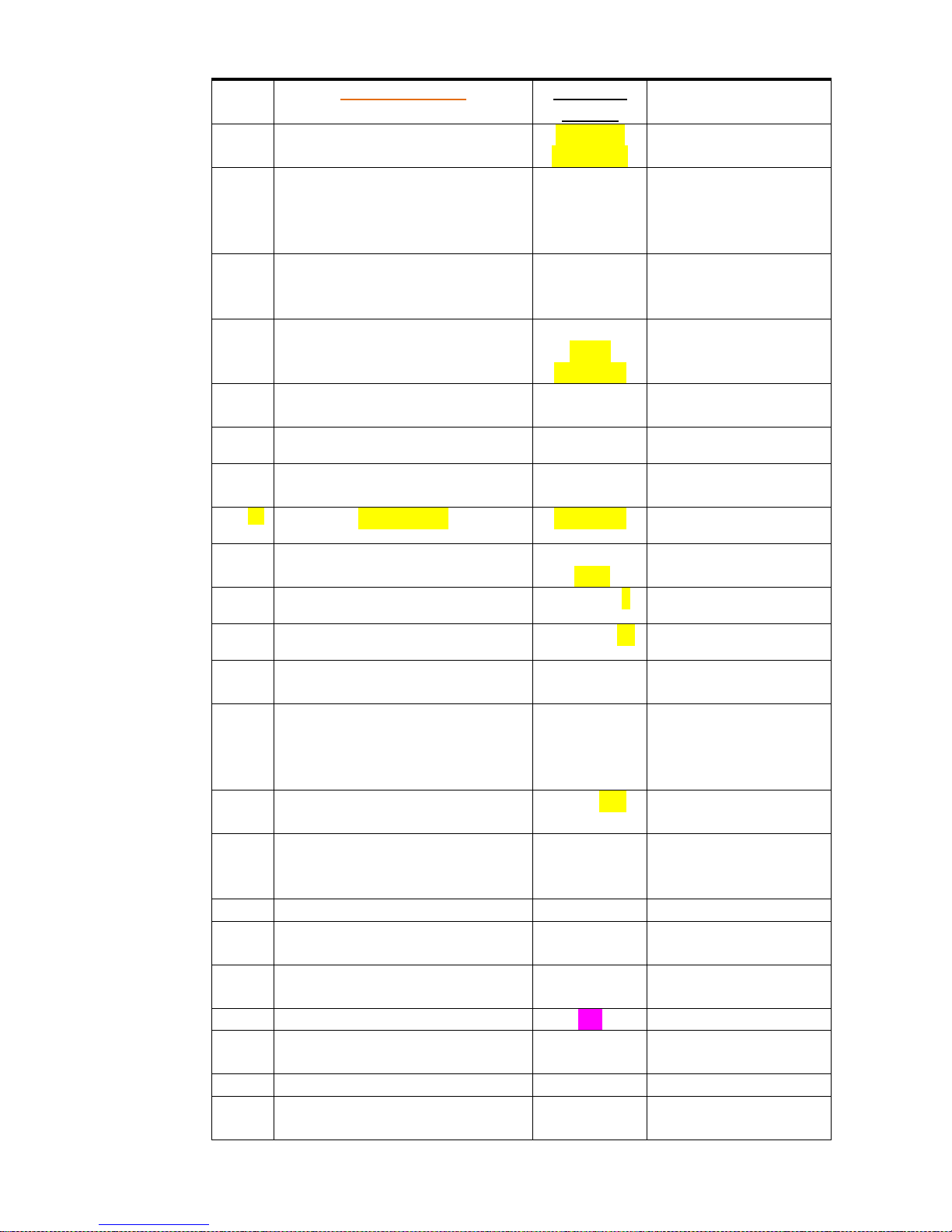
Operation
settings
ENGINEER MENU
Min: 21A
Max: 110A
Current Limit
13
Maximum voltage that
the motor can receive
(over 24v the supply is
cut off)
24V
Output Voltage
14
Current :
130A
Time : 10 s
Drive Boost
15
Threshold
:120A
Time :10 s
Drive Foldb'k-1
16
Level : 100 %
Temp : 80°c
Drive Foldb'k-2
17
Time : 120 s
Motor Cooling
18
Motor CMP
:20 MΩ
Cmpensation
19
Param1: 8
Parameter-1
21
Param2
:1050
Parameter-2
21
Param 3 : 0
Parameter-3
22
Param 4 : 30
Parameter-4
23
Soft Stop :
On
Soft Sto ?
24
Threshold:
80
Time out : 15
s
Free Wheel?
25
Changing the range of
the pull of the trottle
Gain : 130
Throttle gain ?
26
Dead band
:10%
Throttle D'band ?
27
Off
Iso Test
28
0-Single-ended,1-Wig-
Wag, 2-Unipolar
Type : 1
Throttle Type :
29
Not programmed
Mode :2 Displaced mode :
31
Not programmed
Yes
Check Refs:
31
Pot enabled :
Yes .
Speed Limit Pot :
32
750
Brake Time?
33
yes Brake Check?
34
Page 13
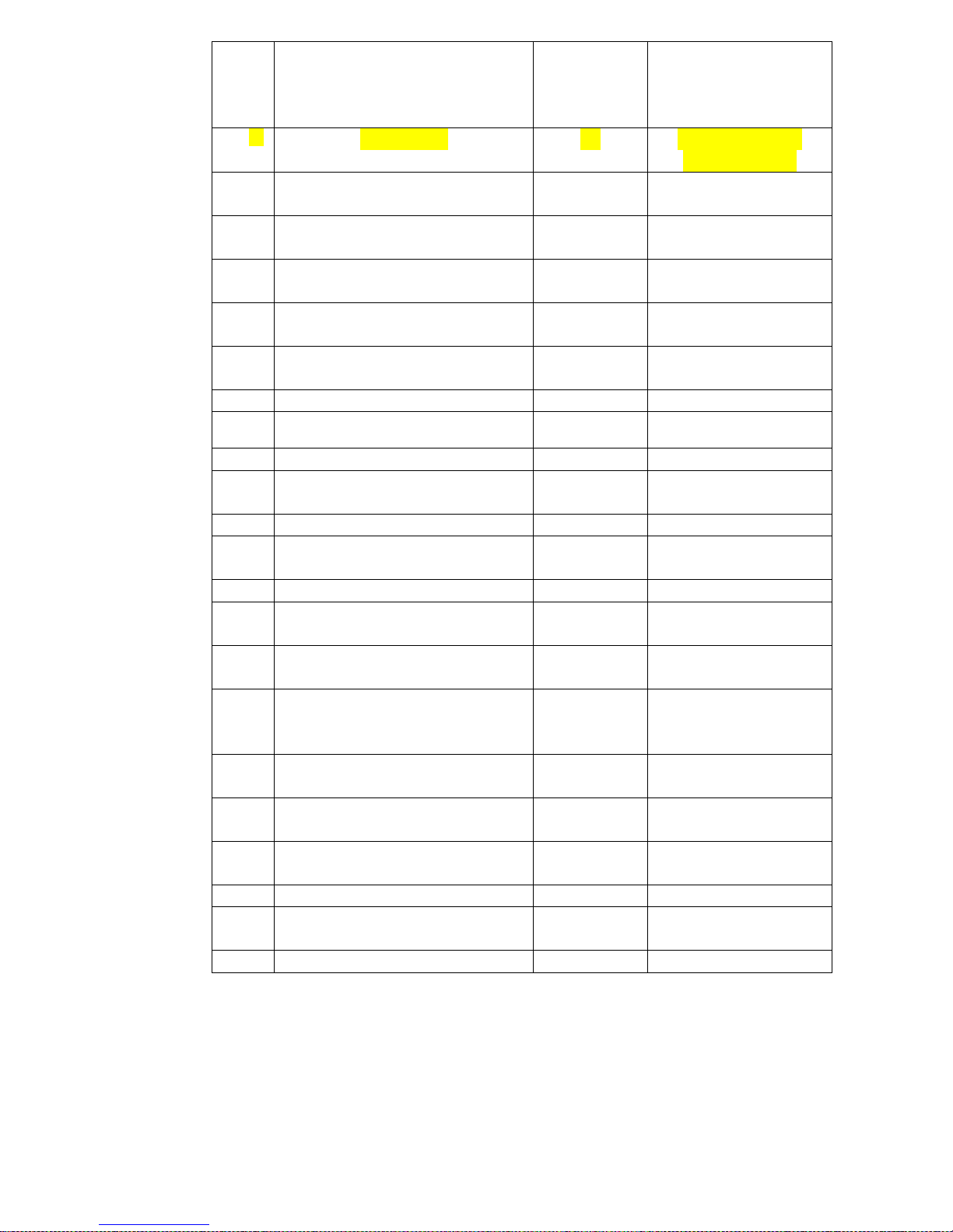
Brake disconnected
Alarm
If using computer
connection "on"
Yes Brake Alarm?
35
If using computer
connection "on"
No Brake Light?
36
0 Status Output?
37
4 Diagnostic Flash
38
If using computer
connection "on"
Yes Diagnostic Alarm
39
Mode :1 Inhibit 1 mode?
40
Speed 0% Inhibit 1 Speed
41
Latched : Yes
Inhibit 1 Latch?
42
Mode:1
Inhibit 2 mode
43
Speed 0 %
Inhibit 2 Speed?
44
Latched: Yes
Inhibit 2 Latch?
45
Mode :1
Inhibit 3 mode?
46
Speed : 0 % Inhibit 3 Speed
47
Latched : Yes
Inhibit 3 Latch?
48
Not programmed
Erase log :
No.
Clear System log ?
49
Not programmed
Clear timer :
No
Clear Timer?
50
With or without beep
when driving
backwards
On/Off Reverse Alarm
51
If using computer
connection "on"
Pulsed : Yes
Pulse Rev Alarm
52
Cable Yes :
40 mΩ
True charge Cable?
53
Calibration:
100
Tru charge Cal?
54
Not programmed
Flash level : 2
Low Batt Flash?
55
Low Bat
Alarm: Off
Low Btt Alarm ?
56
Back to Root ?
Page 14
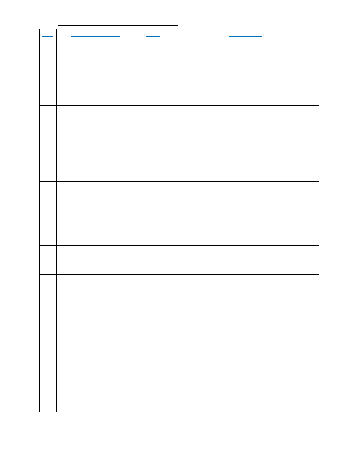
8. Periodic maintenance Check
No.
Type of Service
Who
Frequency
1
Check air pressure in all
tires.
User
Every week
3
Check normal drive and
stop
User
Every Month
4
Check tires wear
User
Every Month
5
Check for missing parts
and damaged parts
.Use the figures
User
When receiving the Breeze C or after a long
time not using it.
6
Check secure of all
screws and parts
Technician
Once a year by technician.
7
Batteries replacing.
Technician
Every 2-3 years , after about 300-400 full cycles
of charge/discharge. When short travel distance
and/or technician check.
Note: To Replace the batteries, the Seat and
Battery Cover located under the Seat must
be removed.
8
Cleaning
User
Technician
External – when needed.
Internal – Once a year.
9
Check power unit
Technician
Check noise , clearance , current on surface
should be 12 to 14 Amp.
Page 15
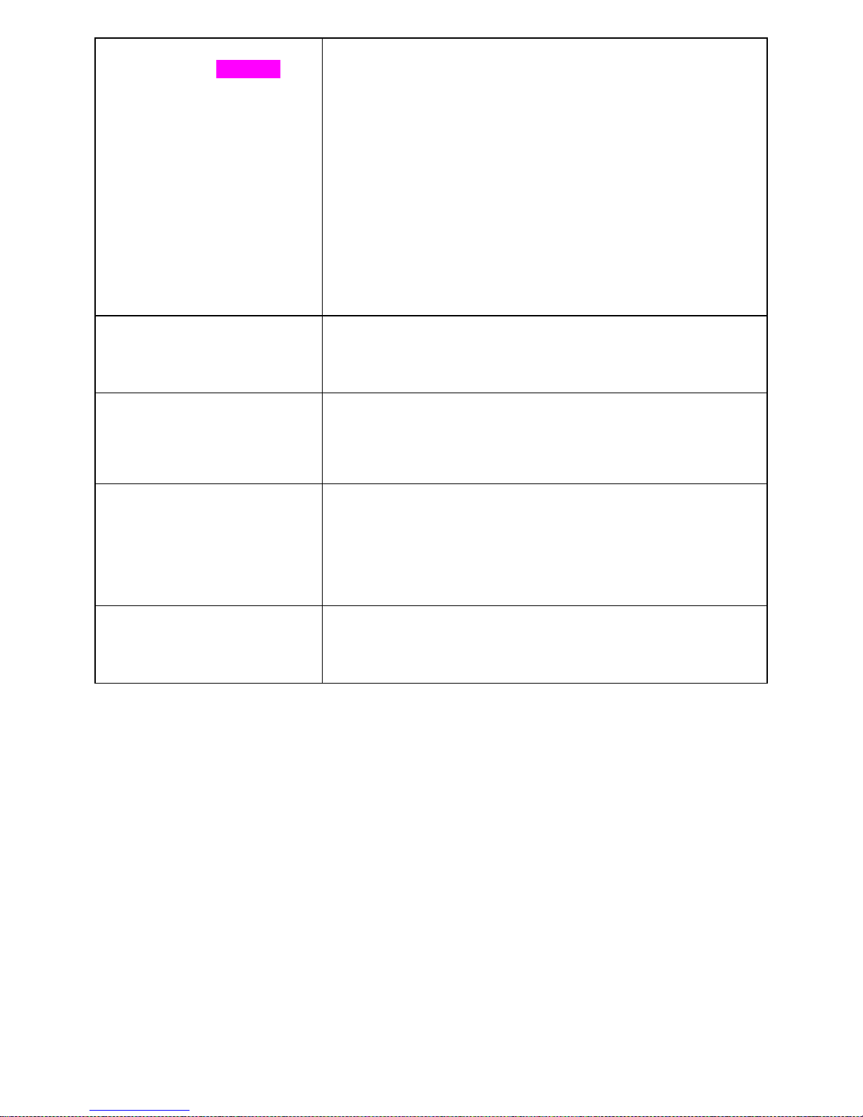
Removing the Seat and the
Batteries Cover (2) ????
Turn the Seat by using the lifting Lever so that the Lever will
point 45º Right or Left. The Seat can be removed only at this
position.
Remove the Seat (7): Hold the Seat in your two hands – one
hand on the backrest and a second hand at the front lower
part of the seat and lift the seat up from its pivot.
Warning! The seat weight is 21 Kg (44lbs).
Keep lifting with your Knees/legs and not loading your Back.
Release Battery Cover (2) securing screws (2.6).
Lift the Battery Cover (2) until it is released from the Seat
Pivot .
Replacing the Batteries
Cover(2)
The replacement of the Cover is done in reverse order;
MAKE SURE that the Cover (2) fits onto it’s place. Secure
with the 4 screws (2.6).
Batteries
Batteries weight each ~14 Kg (~30 lbs) and over.
Lift each battery only with the appropriate handle. Keep
lifting with your Knees/legs and not loading your Back.
Tires
Correct air pressure in the tires is essential for optimal
steering and stability of the Breeze C. Check air pressure
every two weeks.
Inflate to the proper air pressure: 25 ±2 psi. Breeze 4W front
tires: 25±2 psi. Golf wheels tires : 25±2 psi.
Cleaning
Use only a damp cloth and mild detergent. Never use a hose
for cleaning. This may severely damage the power and
electronic components.
Page 16

9. Mechanical Fault troubleshooting
#
Description
Probable cause
Repair action
1
Noises from front
steering and
suspension
system
Check front suspension for
clearances and secure of bolts.
Check front shock absorbers.
Check the ,rod end for
clearance.
Replace wear parts,
secure bolts.
Replace if needed.
2
Front suspension
not functioning
properly.
Check front shock absorbers.
Replace if needed.
3
Excessive wear of
front tires after
short period.
Wear of bushings that cause
clearances in the system.
Un adjusted steering system.
Replace wear parts ,
Adjust the steering
and secure.
4
Rear suspension
Noisy.
Wear in power unit absorbing
Rubbers.
Check for clearances and
unsecured parts.
Check the shock absorbers.
Replace the
absorbing rubbers if
needed.
Secure parts.
Replace shock
absorbers if needed.
5
Rear suspension
not functioning
Check user weight and the fit
of the absorbers.
Faulty shock absorbers
Replace if needed
Replace if needed
6
Noise from power
unit.
Wear in power unit
Check and replace
power unit if needed
7
Too short distance
travel between
charging
Power unit wear, consume high
current. Also might be noisy.
Battery – low voltage -
Check noise and
current and replace if
needed.
Replace the battery.
Check the charger.
Page 17

8
Clearances in tiller
Unsecured screws and gas
piston faulty
Check secure of
screws. Replace gas
piston if needed.
9
Scooter does not
have power or
does not brake
well or go to high
speed downhill.
Wear in motor brushes.
Replace motor
brushes.
10
Noises from motor
Wear of brushes.
Faulty motor.
Check brushes and
replace if needed.
Replace motor.
11
Flat tire and
uneven and not
smooth drive
Flat tire
Repair / replace tire's
tube.Take out the
cuver. Open the
central nut.Take out
the air. Open the 4
screws.
Replace the tube.
Inflate the tub a little
bit before assemble.
After assemble inflate
to 25 +/- 2 psi.
Page 18

10. Control and Electronics system fault troubleshooting
10.1 General control system and Front Board Troubleshoots
The front board is the center of all peripheral functions of the scooter : Lights , Horn ,
Information goes to the LCD display .
Elimination troubleshoots:
The Front Board wiring connections are all quick connectors.
If you suspect the Front Board to be faulted we recommend as a quickest way to find if the
Front Board is faulty, Doing by elimination – Just replace temporarily the Front Board with
another working one and thus make sure if the problem is within the Front Board or
somewhere else.
Check all connection of the Front Board, following the wiring diagram that can be found within
this maintenance manual.
Check main and Charging fuses, located near the rear wheels.
Also always check related function switch , as example Light does not work , first check the
light switch for continuity ,when is in ON position. Use the wiring diagram to figure the proper
terminals to check each function switch terminals.
Trouble Shoot Table:
#
Description
Probable cause
Repair action
1
Front light doesn't work
Front LED board faulty
Replace front LED board
Front Board faulty
Replace Frond Board
2
Front Blinker/s doesn't work
Front Blinker board faulty
Replace front Blinker board
Front Board faulty
Replace Frond Board
3
Rear pilot/s light does work
Rear Blinker board faulty
Replace Rear Blinker board
Front Board faulty
Replace Frond Board
4
Rear Blinker/s doesn't work
Rear Blinker board faulty
Replace Rear Blinker board
Front Board faulty
Replace Frond Board
5
Horn does not work properly
Horn is faulty
Replace Horn
Horn is faulty
Replace Frond Board
Front Board faulty
Replace Frond Board
6
Hazard doesn't work
Hazard switch fault
Check switch and repair
Front Board faulty
Replace Frond Board
7
Reverse function doesn't work
Reverse switch fault
Check switch and repair
Front Board faulty
Replace Frond Board
8
Electric EMB release function
does not work
EMB release Switch
faulty
Check switch and repair
10
No Charge start
Charger fault
Replace charger
Charge fuse popup or
faulty
Reset /Replace charge
fuse
11
Travel distance very low
Charger fault
Replace charger
Old / Weak batteries
Check Batteries / charge
batteries, Replace if
needed.
13
No power or main fuse pop out
Over load
Mechanical fault
Fault controller
Faulty power unit
Short circuit occur
Try to reset 2 times.
Troubleshoot the fault.
Replace the controller.
Replace the power unit.
Find and repair short
circuit.
Page 19
10.2 Controller Troubleshoots
The controller is the center of all driving functions of the Breeze S: Speed control ,
acceleration , deceleration , EMB (Electro Magnetic Brake used as parking brake) , Reverse
drive , Speed limiting etc. . But still the functions of the controller are all connected to all the
wiring, connectors and as well the Front board, power units and batteries.
If any driving misbehave occur
Elimination troubleshoots:
The controller wiring connections are all quick connectors.
If you suspect the controller to be faulted we recommend as a quickest and way to find if the
controller is faulty, Doing it by elimination – Just replace temporarily the controller with
another working one and thus make sure if the problem is within the controller or somewhere
else.
Check all connection of the controller, following the wiring diagram that can be found within
this maintenance manual.
Trouble Shoot Table:
#
Description
Probable cause
Repair action
1
Power is On in the LCD
display but Scooter
does not drive. No code
shown.
Controller fault
Wiring connectors fault.
Front board fault
Replace controller
Check repair wiring /connector.
Replace front board.
2
The "LED" On/Off
Indicate the problem
By flash code sequence
2.2
* *
Low battery .
Battery empty .need to recharge
Change the charger.
Replace the battery.
2.3
* * *
High Battery voltage
Check the charger.
2.5
* * * * *
E.M.B problem.
Check the wire from E.M.B,
Change the E.M.B.
2.6
* * * * * *
Throttle trip
The accelerate lever pressed
while turn the key switch to On.
Check the wires to the controller
2.7
* * * * * * *
Throttle trip
The accelerate lever pressed
while turn the key switch to On.
Check the wires to the controller
2.8
* * * * * * * *
Motor disconnect
Check the wires to the Motor.
2.9
* * * * * * * * *
Controller fault
Replace the Controller.
3
Power is On display and
a code is shown.
Scooter does not drive .
A known fault of the
controller has been found
See follows Fault Bars table and
repair the according.
4
No power is On panel
display.
Power supply or another
control system
Follows (10.1)- General Control
system trouble shoot.
5
Jerky movement
Uncharged batteries.
Weak /Old batteries.
Charge / Check batteries and
replace if needed.
Page 20

Controller faults: Can be found using the LCD fault indication within the battery indicator as
detailed in the follows paragraph.
Error massage will should displayed in the LED "ON" . Further specification of the fault can
be found using the SP1 programmer. When the fault exists, connect the SP1 programmer's
connector directly to the controller SDRIVE120 or to the charging socket, using a special
wiring adaptor.
Page 21

10.3 - The fault code from the SP1 Programmer :
More codes you can see on the hand programming SP1 .
Page 22

11. Mechanical assembly drawings
See attached assembling drawings: "Breeze C (3, 4W) assembling.pdf".
12. Spare parts list .
See attached file.
Page 23
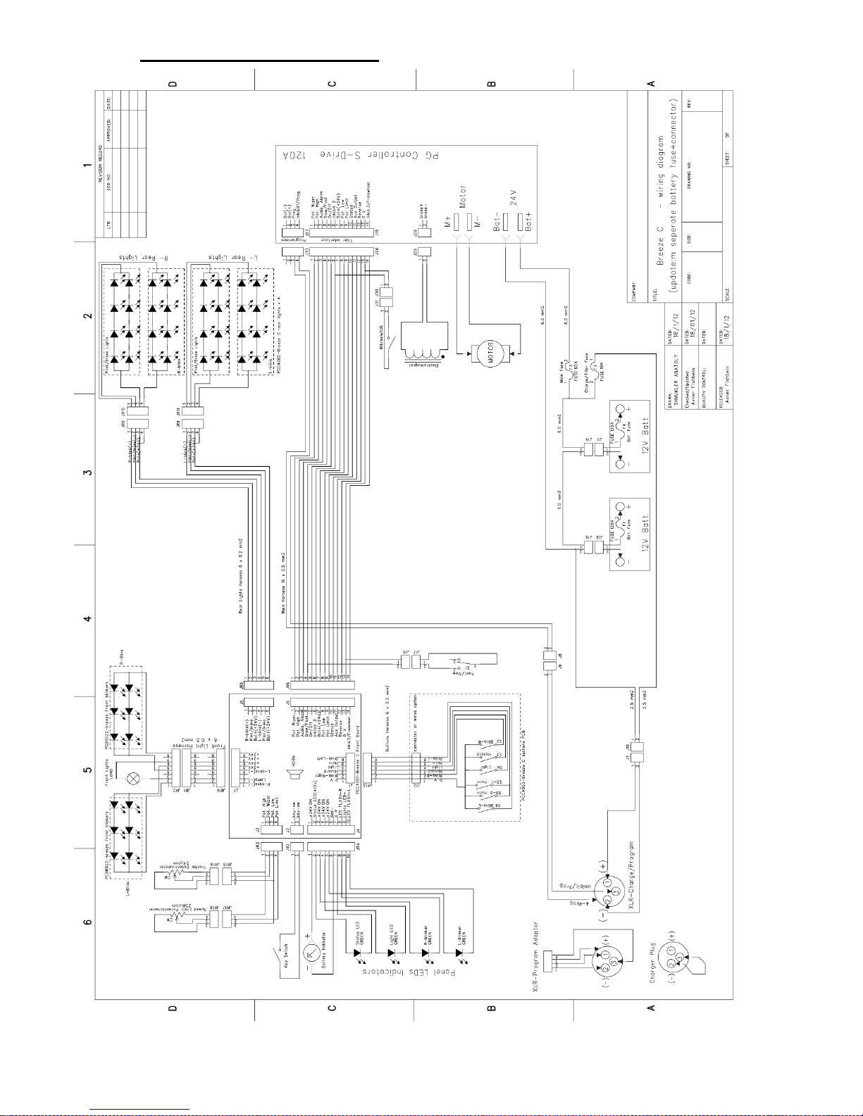
13. General Wiring diagram
 Loading...