

Presto Conti Compact Series, Conti Compact CC-13 V, Conti Compact CC-20 V, Conti Compact CC-40 V, Conti Compact CC-30 V Operating And Maintenance Instructions Manual
Page 1

Operating and
maintenance instructions
CHANNEL-TYPE BALING PRESS
TYPE
CONTI COMPACT
CC-13 V
CC-20 V
CC-30 V
CC-40 V
04/2012
Page 2

5.7 Funnel with safety circuit
1. Introduction
1.1 Introduction
1.2 Structure of the operating
instructions
1.3 Duties and information for
the machine operator
1.4 All rights reserved
2. Intended use
2.1 Improper use
2.2 Amendments at the supplied
device by the operator
2.3 Residual risks at the channel
type baling press
3. Safety
3.1 General information
3.2 Safety instructions
3.3 Safety marking
3.4 Protective devices
3.5 Organisational measures
3.5.1 General information
3.5.2 Location
3.5.3 Selection and qualification
of staff
3.6 Operation
3.6.1 Normal operation
3.6.2 Danger areas
3.6.3 Reference to special
dangers
3.6.4 Transport and loading
3.7 Maintenance/Repair
3.8 Liability and warranty
3.9 Product liability
3.10 Warranty
4. Technical data
4.1 Sound emission
1-1
1-1
1-2
1-2
1-3
2-1
2-1
2-1
2-1
3-1
3-1
3-3
3-3
3-4
3-5
3-5
3-6
3-6
3-7
3-7
3-9
3-9
3-10
3-11
3-12
3-12
3-12
4-1
4-4
5. Constructive description
5.1 General information
5.2 Basic construction
5.3 Press unit with channel
adjustment
5.4 Hydraulic unit
5.5 Electrical unit
5.6 Tie-off device
5.6.1 Fully automatic tie-off
device
6. Operating elements and
operation
6.1 General information
6.2 Operating elements
6.3 Works prior to initial
commissioning
6.4 Compacting process
6.4.1 Operation mode "Manual"
6.5 Control and program
description
6.6 Insert binding wire coils
6.7 Transport and loading
7. Maintenance
7.1 General information
7.2 Cleaning
7.3 Maintenance
7.3.1 Maintenance schedule
7.3.2 Description of the
maintenance works
7.3.3 Fuels, fuel quantities
8. Repair
5-1
5-1
5-2
5-3
5-4
5-6
5-8
5-8
5-8
5-10
6-1
6-1
6-1
6-2
6-4
6-5
6-11
6-15
6-19
7-1
7-1
7-2
7-3
7-3
7-6
7-19
8-1
04/2012
i
Page 3

9. Behaviour in case of trouble
9.1 Error messages
10. List of spare parts
11. Appendix
11.1 List of machine operators
and personnel in charge
11.2 Maintenance and revision
list
11.3 Special equipment
11.3.1 Funnel
11.3.2 Special equipment
11.4 Wiring diagrams
11.4.1 General
11.4.2 Wiring diagrams for the
channel type baling press
11.5 Disposal
9-1
9-2
10-1
11-1
11-1
11-3
11-4
11-4
11-5
11-5
11-5
11-5
11-6
04/2012
ii
Page 4

additional components the machine must
1 Introduction
be assembled before it is put into
operation. Until the machine has been
1.1 Introduction
Dear customer,
to assure a safe and efficient use of the
unit we would ask you to read the present
operating instructions carefully prior to
the initial start-up.
The operating instructions contain all
relevant information for the operation and
maintenance of the channel-type baling
press.
Chapter 1 to 10 will inform you about the
standard equipment. If installed, the
special equipment will be dealt with in
chapter 11.
These operating instructions form a
constituent part of the complete
documentation for the channel-type
baling press of the types CC-13, CC-20, CC30 and CC 40.
Other essential parts are:
• Electrical and circuit diagrams,
• Assembly or layout diagram
completely assembled, commissioning of
individual components is forbidden.
As a rule all safety instructions have to be
fulfilled prior to the commissioning of the
channel-type baling press.
Only qualified and trained personnel of
PRESTO or persons authorised by them
may work with the channel-type baling
press.
If maintenance works are neglected or
carried out improperly we will not be able
to fulfil our guarantee obligations
according to our terms of delivery.
Only original-PRESTO- spare parts ensure
quality and interchangability.
How to identify your machine:
These operating instructions serve for the
operation and maintenance and apply for:
Project: Channel-type baling press
Type: ______________________
(see type plate)
Mach.- No.: ______________________
(see type plate)
• Declaration of Conformity or
alternatively Declaration of
Incorporation
In principle, every machine is supplied
with a Declaration of Conformity. This
states that the machine fulfils the basic
safety and health requirements of the EC
Directive on Machines.
In the event that no Declaration of
Conformity is issued, the attached EC
Declaration of Incorporation for
incomplete machines states with which
04/2012 1-1
Page 5
PRESTO
GmbH & Co. KG
Bad Laer
Conformity with EC-directive 2006/42/EG
To observe upon delivery
The channel-type baling press left our
plant in a technically perfect and ready to
use condition. Please check the condition
of the machine immediately upon receipt
and carry out a functional check. Possible
complaints have to be reported to the
forwarding agent immediately.
1.2 Structure of the operating
instructions
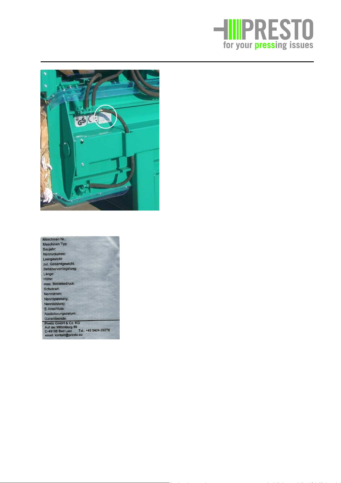
The type plate is positioned at the
channel-type baling press as follows:
When contacting our service department
you should always have the information
ready which is given on the type plate.
Manufacturer: PRESTO GmbH & Co. KG
Customer:
______________________
Year of construction:
______________________
The operating instructions are laid down
in chapters according to the table of
contents.
The corresponding page number has been
assigned to each chapter.
The footnote contains the date of issue
and the page number.
04/2012 1-2
Page 6

PRESTO
GmbH & Co. KG
Bad Laer
Maintenance and repair instructions
1.3 Duties and information for the
machine operator
As the operator of this unit you have to
inform and instruct the operating staff
about prevailing legal regulations and
• Correct dealing with fuels
• Special experiences of the operator
for the cleaning and care,
maintenance and repair of the
machine
accident prevention rules as well as safety
and operating devices at the machine.
Ensure that your operating staff has
understood the instruction and follows it.
How to achieve a safety and danger
conscious operation by your staff:
In the following we have prepared some
items for you with respect to the
instruction subjects
With respect to safety
1.4 All rights reserved
All technical data, descriptions and photos
are valid on the day of the publication of
these instructions or its supplements. We
reserve all rights as well as amendments
by continuous further development.
The operating instructions serve for the
instruction of the customers. It may
neither in part nor fully be copied or
handed to third parties without the prior
written consent of PRESTO GmbH & Co.KG
• Accident prevention rules
• General legal regulations
• General safety instructions
• Measures in case of emergency
• Safety instructions for the
operation of the unit
• Dealing with the safety devices of
the machine
• Meaning of symbols and signs
With respect to the operation of the
machine
• Dealing with the operating
elements
• Explanation of the operating
instructions for the operating staff
• The use of aids and auxiliary
devices
• Experiences with regard to the use
of the machine
04/2012 1-3
Page 7

PRESTO
GmbH & Co. KG
Bad Laer
The channel-type baling press has been
constructed for the compaction of soft
materials as paper, cardboard, foils and
similar.
2.1. Improper use
Explosive materials or similar materials or
combustible materials may not be filled in.
It is also prohibited to charge rumble, wood,
form or bar racks from metal or other hard
materials, which can result in a jerky
jamming of the compressing die.
2.3. Residual risks at the channel-type
baling press
Danger by nonobservance of the
operating instructions
Danger by insufficient maintenance
and repair
Risks arising during maintenance,
servicing, and repair work through
the use of sharp-edged or
inappropriately compacted materials
(see note in chap. 7, Maintenance
and Inspection).
The operator is responsible for these residual
risks.
2.2. Amendments at the supplied device
by the operator
The declared conformity applies only to the
structural condition upon delivery of the
device in correspondence with the agreed
scope of delivery. Any installation or
equipment which is carried out by the
operator at a later time, however, has not
been developed or authorised by the
manufacturer of the machine, will result in
an expiry of the declared conformity.
This also includes unauthorised modifications
of the channel-type baling press with sheets,
wood, pasteboard or fabric of any kind by
the operator.
04/2012 2-1
Page 8

3. Safety
We wish to point out that the unit has to be
checked at least twice a year by a qualified
person with respect to the proper and safe
3.1. General
To safeguard the labour protection and the
on-the-job safety the following references
have to be adhered to:
Accident prevention regulations, in
particular:
BGV A1 General Regulations
BGV A2 Electrical systems and
operating resources
BGV A5 First Aid
BGV B3 Noise
BGV A8 Safety marking at the work
site
have to be adhered to.
The accident prevention rules of the country
where the unit will be used have to be
observed.
function in correspondence with the above
mentioned directives.
In addition to the above mentioned
regulations the following directives are
appropriate for the inspection as well:
Safety of machinery DIN EN 12100
Part 1 u. 2
Electrical equipment DIN EN 60204
EC- machinery
2006/42 EG
directive
During the operation of the machine the
laws and regulations applicable at the place
of use have to be observed. For the sake of a
safe work sequence the operator,
supervisory persons and machine operators
are responsible for observing the regulations.
The channel-type baling press may only be
used as directed. An improper use can result
in personal and property damages.
The PRESTO channel-type baling press has
been constructed for the compaction of soft
materials as paper, cardboard, foils and
similar.
04/2012 3 - 1
Page 9
It is prohibited to load explosive or similar
materials or inflammable materials
(according to §1 SprengG).
Materials that are subject to special
conditions of disposal according to the waste
disposal law must not be loaded.
Furthermore it is prohibited to fill with
rumble, timber or other such materials out of
metal or other hard materials. Only such
material may be compacted which can be
deformed by the given pressure and which
can be compressed in the compression room.
Glowing or burning particles must not be
loaded.
Another use or a surpassing use does not
comply with the intended purpose. PRESTO
GmbH & Co.KG will not be liable for damages
resulting from this. The risk will be borne by
the user of the machine.
DANGER!
The electric machines
and/or equipment are
production equipment for
use in industrial high
voltage systems. During
operation this production
equipment has dangerous
live parts which may
cause very serious injury
to health or damage to
property for instance as a
result of unauthorised
removal of coverings,
improper use, incorrect
operation or lack of
The staff responsible for the safety of the
unit has to safeguard that only qualified
persons
are instructed with work on the machinethat these persons always have the supplied
operating instructions available and that they
are obliged to strictly adhere to these
documents. Working at the unit or in the
proximity has to be prohibited for nonqualified personnel.
During filling the compactor with
material that may cause skin
damage wear gloves!
Pay attention to flying solids!
Use eye protection!
At places where there are solid airborne
particles or where dusts, caustic substances
or the like are processed or produced.
Residual risks with regard to the channeltype baling press:
• Endangering by failure to comply with
safety instructions
• Danger by insufficient maintenance and
repair
• Risks through hydraulic hoses
• Risks through sharp-edged casing corners
• Risks arising during maintenance,
servicing, and repair work through the
use of sharp-edged or inappropriately
compacted materials (see note in chap. 7,
Maintenance and Inspection).
The user will be responsible for these
residual risks.
maintenance.
04/2012 3 - 2
Page 10
3.2. Safety instructions
The following symbols in these operating
instructions mean:
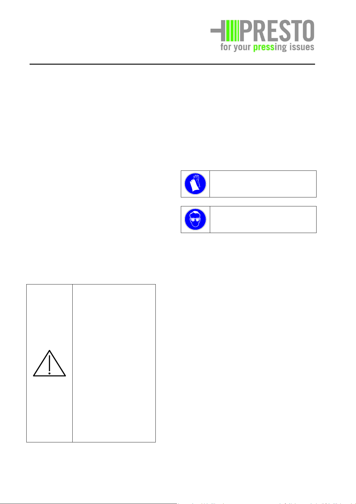
Risk to life and limb!
Caution!
This maintenance work may
only be carried out by skilled
personnel.
Additional important
information can be found here.
3.3. Safety marking
Safety instructions and the brief version of
the operating instructions are visible at the
machine
Note:
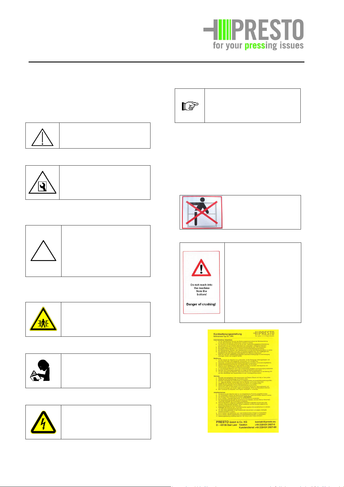
CAUTION!
NEVER CLIMB INTO THE
FEEDING OPENING!
DANGER!
Caution!
Risk of damage to or
destruction of the machine
or its parts.
Danger of crushing!
Do not reach into the
machine from the
bottom!
Caution!
Risk of crushing!
Read and understand
the manual!
Caution!
Risk from electric current!
04/2012 3 - 3
Page 11
3.4. Protective devices
Safety switch, charging funnel
It is prohibited to put control, switching or
safety devices out of operation or to make
modifications. Non-compliance may result in
criminal prosecution.
Safety covers held in place by bolts which fit
through keyhole-shaped slots are removed
from the machine by loosening the bolts 3 or
4 turns. The bolts should remain in the drill
holes. The cover can now be slid along the
keyhole and removed by lifting over the bolt
heads which fit through the round, upper
keyhole aperture. The covers are replaced by
reversing the sequence.
Seals may not be destroyed and pre-set
Safety switch with rope release (1)
pressures may not be changed because this
would result in an expiration of the warranty
and criminal prosecution.
Equipment for the protection of the staff:
rgency-off switch, switch box
Emergency-off, key bar
04/2012 3 - 4
Page 12
Safety switch (Type CC-30 only)
3.5. Organisational measures
3.5.1. General
The operating instructions always have to be
kept at the intended place.
In case of multiple shift operation it has to be
determined who will be responsible to carry
out the maintenance works.
Cover, manual tie-off device
Check machine with regard to external
recognisable and/or audible damage and
defects, at least once per shift. Stop and
secure machine immediately if necessary.
Before starting the work the operational
tests at the emergency-off switch and the
safety switch and light barriers if necessary.
ATTENTION!
Any work such as taking into operation,
maintenance and repairs may be performed
by qualified staff only and have to be
checked by responsible experts. The user has
to notify any trouble or irregularities to his
person in charge immediately. This applies
for the mechanical and electrical devices.
The machine has to be stopped and secured
Safety switch needle flap
immediately in case of malfunctions or
safety-relevant changes of the behaviour of
the machine. Malfunctions have to be
corrected immediately.
It has to be seen to it that the operating
instructions, the maintenance and special
tools and devices, the oil cans and grease
guns as well as cleaning agents and
lubricants belonging to the channel-type
baling press container are always kept in the
intended receptacles.
04/2012 3 - 5
Page 13

with machinists who have been instructed
3.5.2. Location
The location has to be chosen that way that
the channel-type baling press stands on a
plain surface. The location must have a
concrete plain surface that corresponds to
the weight of the machine.
The unit may be operated in an electrical
network with the corresponding conditions
(see chapter "electrical system").
As a protective measure against indirect
touching the fault-current circuit breaker
according to VDE 0100 has to be used when
erecting the machine in the open. Only faultcurrent circuit breakers may be used with a
nominal fault current as specified in the
wiring diagrams of the manufacturer.
The provisions of the water household and
environmental protection law have to be
about the use of the machine according to
BGV A1 § 13. The above mentioned is only
valid for the Federal Republic of Germany.
The corresponding regulations and guidelines
of the country where the machine is used are
applicable.
Only qualified and reliable staff may work at
and with the machine.
Persons instructed with work at/with the
machine must have thoroughly read and
understood the operating instructions and
here especially the safety instructions and
they must be in a corresponding mental and
physical state.
Non-compliance with these instructions may
result in danger for life and limb and/or
danger for the machine or other physical
assets.
adhered to when setting up the unit and
taking it into operation.
3.6. Operation
Sufficient space has to be provided in front
of the channel-type baling press for the bale
which is pushed out. The access must be
possible for industrial trucks without
endangering persons.
The loading and starting area for industrial
trucks has to be marked.
The use in explosive areas and in an
explosive atmosphere is strictly prohibited.
The channel-type baling press is appropriate
for manual loading from ground level to the
loading space of the machine. If the loading
takes place from a ramp, PRESTO offers a
3.6.1. Normal operation
corresponding ramp funnel that guarantees
3.5.3. Selection and qualification of
staff
Only such persons selected according to BGV
A1 § 13, BGV A2 are authorised to operate
and maintain the channel-type baling press.
The user will be responsible for the
occupation of the channel-type baling press
the necessary minimum height with regard
to safety.
This means, that the location of the loading
level has to be designed in such a way that a
minimum height to the load opening and to
the laterally fixed loading door (if any) does
not fall below . If the loading level
04/2012 3 - 6
Page 14
varies PRESTO will supply the corresponding
funnel.
When using a lifting/tipping device to empty
the containers according to the dimensions
shown in the appendix, care has to be taken
that no person stays in the swivel area of the
device. Loading from other containers is
regarded as improper use. Using externally
manufactured loading or suction devices is
subject to the agreement of PRESTO.
The user must be aware of the
power supply of the channel-
type baling press as well as
their interrupting possibilities.
Beyond this the user has to be
familiar with the instructions
according to BGV A2.
According to the chapter "Operation" of the
operating instructions the dangerous zones
have to be paid attention to.
Attention!
To avoid malfunctions it is indispensable to
have the maintenance and inspection work
performed at regular intervals. Changes in
comparison with the normal operation
(increased power consumption,
To avoid malfunctions that may either
directly or indirectly result in serious
personnel or property damages, the
responsible maintenance personnel have to
be informed immediately..
Before taking the unit into operation all
protective devices have to be in protective
position and the locking devices and other
protective measures involved in the control
of the machine have to be in function. The
function of the operating elements has to be
checked.
The channel-type baling press must not be
used if the mains lead is not satisfactory.
Using electrical coupling devices and
adapters for the operation of the channeltype baling press is not allowed. Only
plugging devices according to VDE 0113 acc.
to DIN EN 60204 may be used.
The mains plug may be replaced by a
qualified electrician only. In case of a
replacement of the mains lead or equipment
connecting line it is not allowed to deviate
from the type stated by the manufacturer.
The mains plug may not be plugged before
the channel-type baling press has been
properly installed at the location.
temperatures or vibrations, extraordinary
noise or odours, response of control
instruments, etc.) show that the function is
impaired.
04/2012 3 - 7
Page 15

Entering the shaft of the
channel-type baling press is
strictly prohibited.
Before taking the unit into operation make
sure that nobody will be endangered.
Watch turn-on transient and turn-off
transient as well as control lamps according
to operating instructions.
User - decide responsibility.
Enable the user the refusal of instructions
from third parties that impair safety!
Ensure that only authorised persons are
working at the machine. Please keep persons
who are not involved in the work process in a
distance.
The staff may not wear long loose hair, loose
clothes or jewellery including rings. There is a
considerable danger to be injured, for
example by getting caught or being trapped.
Switch off machine when having finished the
work and secure against unauthorised
reclosure (lock main switch).
Comply with adjustment and maintenance
work instructions for the replacement of
parts / part equipment.
This work may be performed by skilled
personnel with sufficient knowledge and
corresponding tools, only.
As far as necessary or if required by legal
provisions use personnel protective
equipment!
Wear protective gloves!
Use eye protection!
at places where there are solid airborne
particles or where dusts, caustic substances
or the like are processed or produced.
It is prohibited to erect platforms, ladders or
other aids.
If there is no possibility of supervision, the
operation has to be locked by the actuation
of the main switch that can be locked by a
key.
The cover to the cylinder room may be
opened for the purpose of cleaning,
maintenance or repair only. For this purpose
the channel-type baling press has to be
disconnected from the power supply.
Additionally the main switch has to be put
into "0" position and be secured against
unauthorised interference by means of a
padlock. After having finished the work care
has to be taken that the flap is mounted
again correctly.
When using oils, grease and other
substances, adhere to the safety regulations
and legal provisions valid for the product!
An immediate interruption by the user is
absolutely necessary if defects occur, which
impair the safety.
Observe protection against accidental risks
(Guideline of the council 2001/45/EC).
04/2012 3 - 8
Page 16
These are:
• Failure of light barriers,
• Emergency-off switches and protective
devices
• • Damaging of electrical equipment and
lines as well as insulators.
In case of doubt immediately stop the
unit!
electrical information in the chapter
"Electrical unit"
Attention!
The rotational direction of the electric
motor of the hydraulic pump has to be
strictly observed. A short time wrong
running destroys the hydraulic pump.
The motor is running correctly when the
ventilator wheel at the electric motor rotates
in the direction of the arrow at the housing
indicating the rotational direction and the
3.6.2. Danger areas
The danger area of the machine is limited to
the horizontal distance measurement of 1 m
to the external dimensions of the channeltype baling press.
compressing die makes a movement
within 5 seconds.
If the compressing die does not make any
movement within this time turn off motor
immediately and change two phases of the
feed line by an electrical expert.
As the pump runs without oil flow in case of
a wrong rotational direction, the motor may
be turned on for a very short time only (5
seconds as a maximum).
Funnel
Before working on electrical units or systems
these have to be switched dead.
The five safety rules before starting work:
Schematic
view
• Switch off
• Secure against reclosure (switch off main
switch and lock)
• Ensure dead circuit
• Grounding
• Cover or screen of adjacent live parts
3.6.3. Reference to special dangers
Electrical energy
The machine will be supplied ready for
operation.
The power connection has to be provided at
the side, doing this the electrical safety
instructions, the regulations and the
04/2012 3 - 9
Page 17

3.6.4. Transport and loading
Use corresponding hoisting equipment and
proper securing measures:
Lift machine at intended loading point only
or use forks of forklift truck only at bearing
parts! See schematic view!
The forks only in places marked by the
Following sign set.
CC 36, Points of notice forks
Secure load against unintended changes of
the position.
Parts that are removed during transit have to
be mounted and fixed again before taking
the machine into operation again!
Transport safety devices and transport aids
have to be removed.
The machine has to be separated from every
CC 13, Points of notice forks
external energy supply also in case of a slight
change of the location of the machine!
Before taking the machine into operation
again, the machine has to be connected to
the mains again properly!
CC 20, Points of notice forks
04/2012 3 - 10
Page 18
3.7. Maintenance / Repair
Staying in the dangerous zone
is allowed only during the
specially described work by
authorized personnel and/or
experts adhering to the
corresponding safety
instructions.
The maintenance of electrical equipment
may be performed by experts or instructed
persons only.
Before the inspection and cleaning of the
electrical equipment the unit must be dead
for the duration of the work.
The machine has to be turned off completely
during maintenance and repair work and be
secured against unauthorized reclosing (see
chapter "maintenance").
Before starting to work on electrical plants or
resources, de-energize them.
Inform operating staff about this point
before starting special and repair work!
Nominate a supervisory person!
Secure dangerous zone!
Tighten loosened connections properly again
during maintenance and repair work!
Dismantled protection- and safety devices
have to be properly mounted again and
checked regarding a tight seat before taking
the unit into operation again!
Use fuses in accordance with regulations and
current intensity only.
It is strictly forbidden to repair fuses!
Welding work on all supporting members are
prohibited.
Maintenance, cleaning and inspection work
may be performed during standstill and
turned-off machine and by authorized
personnel only. The padlock has to be
provided and locked at the main switch in
Do not switch. Work in progress
Place: Date:
This sign may only be removed by:
Attach a telltale sign prior and during work!
Danger!
Before taking the unit into
operation all safety
elements have to be
checked regarding their
function. All protective
covers and doors must be
order to avoid unintended turning on. The
key has to be kept in a safe place by the
supervisory staff or the nominated qualified
personnel.
Keys and tools by which the channel-type
baling press can be put into operation and/or
protective devices can be dismantled, must
be in possession of the instructed authorized
person or be kept in a safe place.
Electrical components or control elements
must not be directly splashed with water.
closed and locked.
04/2012 3 - 11
Page 19
The use of flammable materials (e.g. petrol is
forbidden – BGV A1 § 43 and 44! During
cleaning work, repairs, etc. the main switch
(1) always has to be locked in 0-position with
a padlock.
Operating fuels (e.g. gear lubricant oil) during
maintenance, repair work and oil changes
have to be collected in appropriate vessels
and disposed of according to the regulations
(EC guideline 75/439/EEC and decrees, 5a, 5b
AbfG and AltölV).
This requires the adherence to the applicable
regulations of the accident prevention and
the accepted
technical regulations for safety and proper
working and the operating instructions,
inspection and maintenance regulations valid
in the country of the user and at the location.
Modifications, extensions and
changes of the design of the
machine must not be made
without the approval of
PRESTO GmbH & Co.KG.
3.8. Liability and warranty
The completeness of the scope of delivery
according to the delivery note has to be
checked upon receipt of the machine.
If parts are missing or transport damages are
found, please inform PRESTO GmbH & Co. KG
immediately.
The supplied unit has been constructed
according to the latest state of the art and
the accepted safety standards (DIN 12100
part 1 and 2 and DIN EN 60204 T1 and
DIN ISO 13849).
In case of improper use and non-compliance
with the regulations, dangers to life and limb
and trouble of the machine or other tangible
assets might occur.
3.9. Product liability
If non-compliance/non-adherence to the
regulations and instructions of this operating
manual leads to accidents with personal
injury or property damage, PRESTO GmbH &
Co.KG will not be liable for any
damage and the compensation of indirect
damage as injuries of persons, damage to
goods, which do not form the subject of the
contract, loss of profits and production
failure which will be directed to PRESTO
GmbH & Co.KG under the title
"PRODUCT LIABILITY".
The PRESTO channel-type baling press
primarily serves for the compaction of soft
materials as paper, cardboard, foil, etc.
Another or surpassing use may be regarded
as improper use. PRESTO GmbH & Co.KG will
3.10. Warranty
PRESTO will accept the warranty for the unit,
provided that the operating and
maintenance manual is adhered to.
not be liable for damages resulting from this.
The risk will solely be borne by the user of
the machine.
Operate unit in a technically good order and
according to the regulations.
04/2012 3 - 12
Page 20

4. Technical data
Type CC-13 fully automatic
Pressing power kN 130
Spec. pressing power N/cm2 24,8
Channel cross section mm 700 x 750
Charging opening mm 750 x 750
Filling volume max. m3 0,39
Power kW 5,5
Volume in idle running m3/h 59
Volume under operating conditions m3/h 50
Weight related to the apparent density t/h
- 35 kg/m3 (department store) t/h 1,7
- 60 kg/m3 (mixed products) t/h 2,5
- 100 kg/m3 (collected products) t/h 3,8
Bale weight
Machine weight approx. t 1,9
Tie off – threefold vertically
Electric connection – standard plug CEE form, 5
pole, fuse protection
Lifting time s 24
Type CC-20
Pressing power
Spec. pressing power
Channel cross section
Charging opening
Filling volume max.
Power
Volume in idle running
Volume under operating conditions
Weight related to the apparent density
- 35 kg/m3 (department store)
- 60 kg/m3 (mixed products)
- 100 kg/m3 (collected products)
Bale weight
Machine weight approx.
Tie off – threefold vertically
Electric connection – standard plug CEE form,
5 pole, fuse protection
Lifting time
Depends on and bale length
wire ∅ 2,8
A 16
fully automatic
kN 200
N/cm2 38,1
mm 700 x 750
m3 1000 x 750
m3 0,53
kW 7,5
m3/h 80
m3/h 77
t/h
t/h 2,7
t/h 3,4
t/h 4,8
Depends on and bale length
t 2,7
A 32
s 24
wire ∅ 2,8
04/2012 4 - 1
Page 21

30 fully automatic
Pressing power kN 300
Spec. pressing power N/cm2 45,0
Channel cross section mm 700 x 950
Charging opening m3 1030 x 950
Filling volume max. m3 0,68
Power kW 11,0
Volume in idle running m3/h 72
Volume under operating conditions m3/h 58
Weight related to the apparent density t/h
- 35 kg/m3 (department store) t/h 2,0
- 60 kg/m3 (mixed products) t/h 3,2
- 100 kg/m3 (collected products) t/h 4,8
Bale weight
Machine weight approx. t 3,7
Tie off – threefold vertically
Electric connection – standard plug CEE form, 5
pole, fuse protection
Lifting time s 34
Depends on material and bale length
wire ∅ 3,1
A 35
Type CC-40 fully automatic
Pressing power kN
Spec. pressing power N/cm2
Channel cross section mm
Charging opening m3
Filling volume max. m3
Power kW
Volume in idle running m3/h
Volume under operating conditions m3/h
Weight related to the apparent density t/h
- 35 kg/m3 (department store) t/h
- 60 kg/m3 (mixed products) t/h
- 100 kg/m3 (collected products) t/h
Bale weight
Machine weight approx. t
Tie off – threefold vertically
Electric connection – standard plug CEE form, 5
pole, fuse protection
Lifting time s
Depends on material and bale length
A
400
48,5
750 x 1100
1030 x 1100
0,85
15
90
72
2,5
4
5,9
4,2
Wire 2,8-3,1
35
34
04/2012 4 - 2
Page 22

Dimensions (mm)
Typ A B C D E F G H L M
CC-13 V
CC-20 V
CC-30 V
CC-40 V
1225 1475 1830 380 1050 600 1560 1400 2800 750
1225 1475 2030 380 1135 700 1900 1650 3300 750
1225 1475 2130 380 1350 700 2540 1800 3700 950
1275 1575 2200 380 1640 750 2540 1800 4200 1100
M = Semiautomatic V = Fully automatic
04/2012 4 - 3
Page 23

4.1. Sound emission
The sound intensity level was measured according to EN 23744.
The sound intensity level is stated according to MRL Appendix I, point 1.7.5. f in a free sound
field in a distance of 1 m from the machine and a height of 1.6 m with the highest measured
value.
The sound intensity level measured at the channel-type baling press of the types
• CC-13,
• CC-20,
• CC-30 and
• CC-40 V
is < 75 dB(A).
04/2012 4 - 4
Page 24
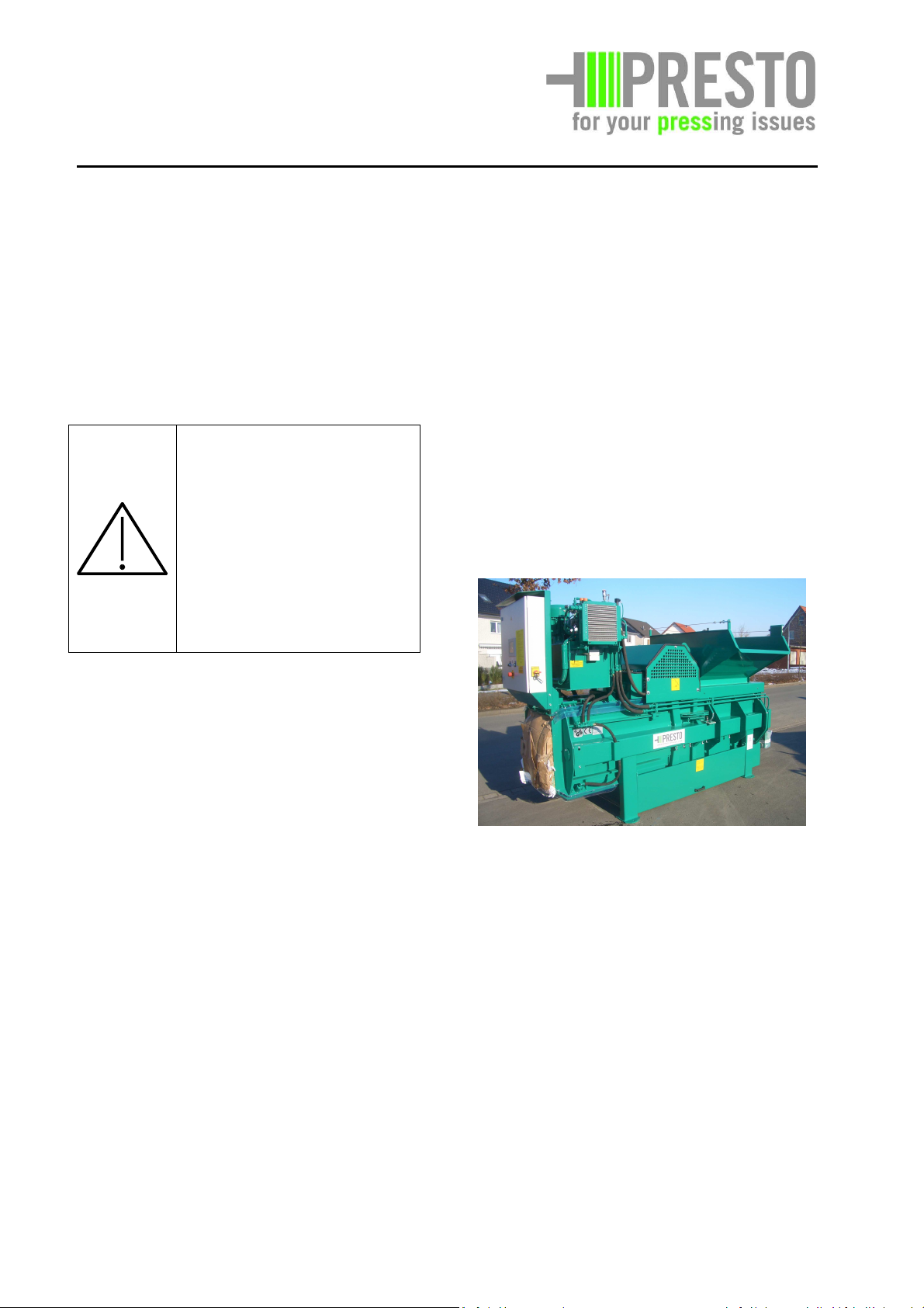
5. Constructive description
Glowing or burning particles must not be
loaded.
5.1. General
For a better representation of the components
we have dispensed with protective covers in
some cases.
Danger!
Before taking the unit into
operation it has to be
ensured that all protective
covers, flaps or sheets have
been duly mounted. They
serve for the protection of
The channel-type baling press is controlled
by a stored program control (SPC). The
compaction of the material is effected by a
compressing die which is moved in the
pressing channel by means of a hydraulic
cylinder. According to the design the pressed
material is tied up to a bale automatically (V).
These operating instructions generally apply
for all machine types of the channel-type
baling press Conti-Compact CC-13, CC-20, CC-
30 and CC-40 V.
the staff, however, also for
the proper function of the
machine.
The PRESTO channel-type baling press has
been constructed for the compaction of soft
materials as paper, cardboard, foil, etc.
It is prohibited to load explosive or
assimilated materials or inflammable
materials (according to §1 SprengG).
When erecting the unit and taking it into
operation the guidelines of the water
household and environment protection law
have to be adhered to.
Materials that are subject to special conditions
The above illustration only shows machine
type CC-20V.
In case of constructive deviations this is
stated extra. In order to simplify matters the
operating instructions refer to the channel-
type baling press.
for the disposal according to the waste disposal
law must not be loaded.
Furthermore it is prohibited to fill in rumble,
timber or other bar racks from metal or other
hard materials.
04/2012 5 - 1
Page 25
PRESTO
GmbH & Co. KG
Bad Laer
5.2. Basic construction
The basic construction is a steel construction
and, on the whole, it is the housing (A) for the
following components:
• the compressing unit (see section 5.3),
• the channel adjustment (C),
• tie-off device (D) with cover,
• the electrical unit (E), with
• the stored program control - SPC - (F),
• the hydraulic unit (G),
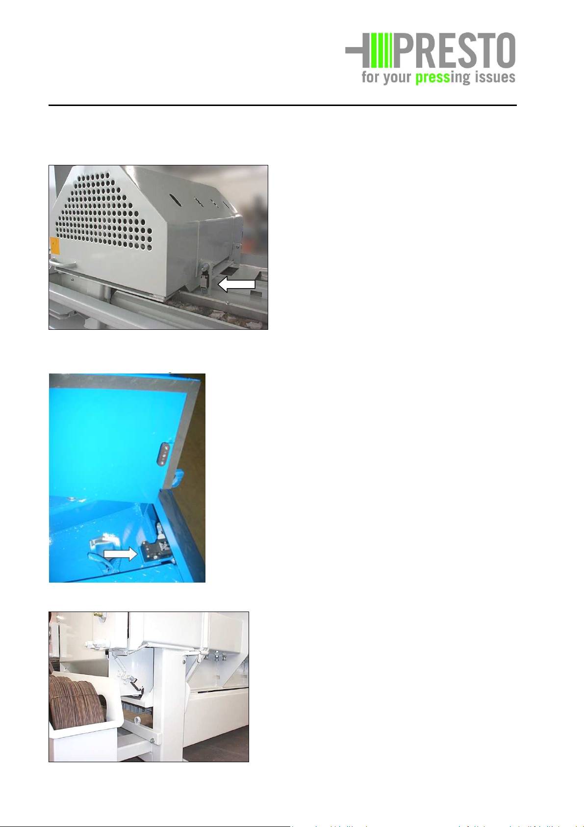
• the funnel with (H) safety circuit.
The components cannot be shown completely
in the following illustration. However these will
be dealt with more thoroughly in the individual
sub-chapters 5.3 to 5.7.
Baling channel with press body (1),
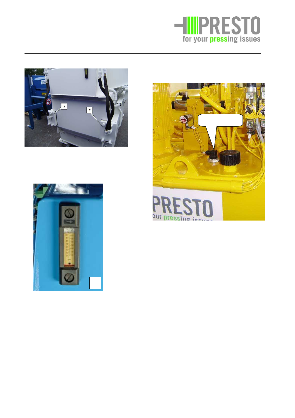
Telescope sheets (2),
Polyamide guide rails (3) for the press body,
Polyamide guide rails (4) for the telescope
sheets,
Hydraulic cylinder (5), see hydraulic unit,
Channel adjustment sheets (6) with
tightening elements (7), and plate for bale
rest.
The press body is moved in the baling
channel by means of two hydraulic cylinders.
The movement of the press body is guided
by polyamide rails. Telescope sheets, which
protect the space behind the press body
against material falling into it, are pulled out
during the pressing movement.
5.3. Compressing unit with channel
adjustment
This assembly is responsible for the compaction
of the material filled in the charging opening.
The assembly mainly consists of the following
components:
04/2012 5 - 2
Knives (9) are provided at the upper side of
the press body or the underside of the
channel entrance. At their cut edge the
knives cut the material filled in. They prevent
the pressure build-up on the upper side of
the press body and thus avoid excessive wear
at the polyamide guide rails.
Page 26
PRESTO
GmbH & Co. KG
Bad Laer
The material to be compacted is pushed into a
narrowing channel. The narrowing avoids that
length has been achieved, serves to tie up
the bale.
a back pressure is building up. A retaining
device avoids the compacted material from
getting back into the pressing channel.
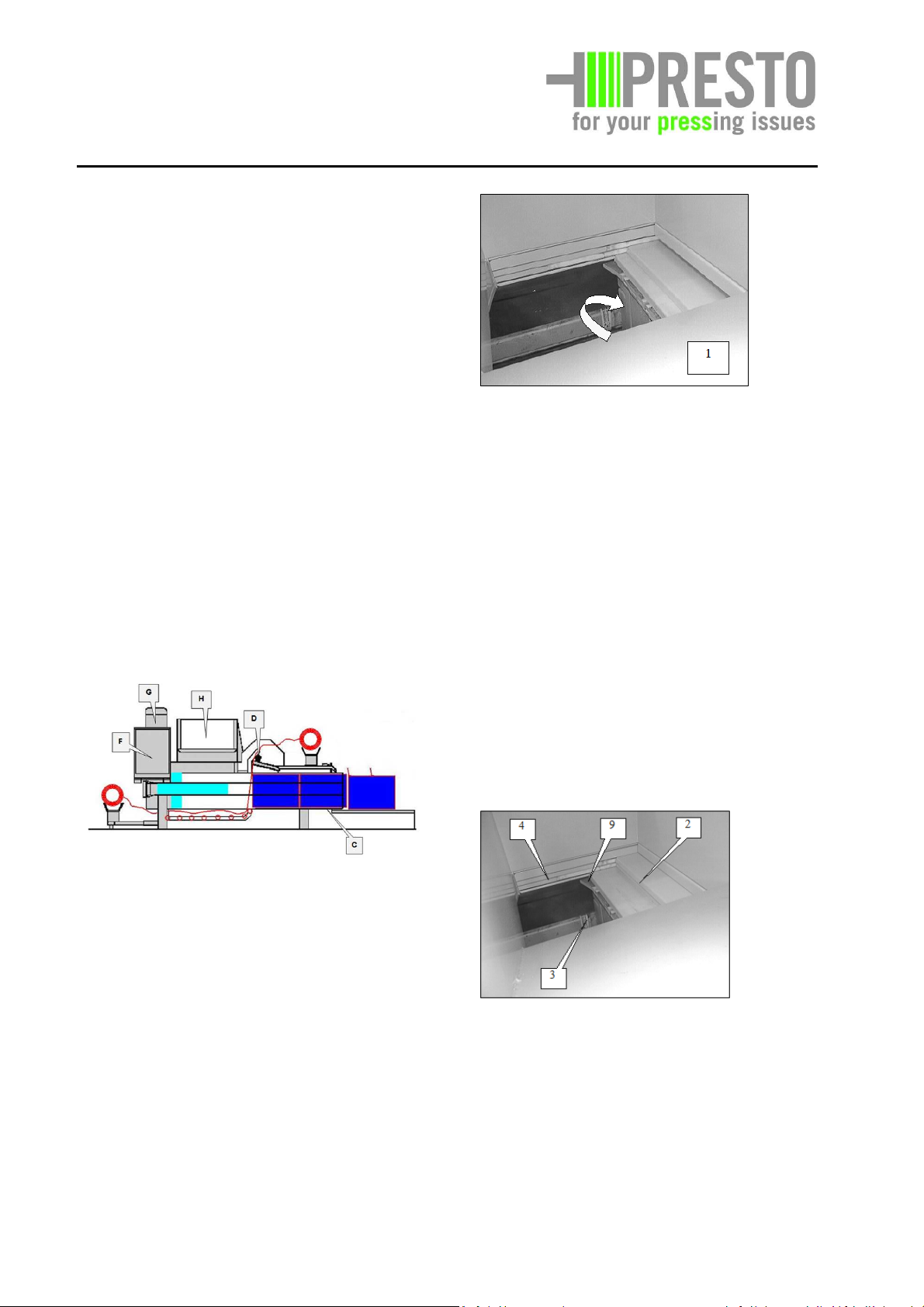
Retaining device – on both sides
Four hydraulic cylinders are mounted at the
channel outlet.
5.3.1. Hydraulic channel adjustment
The material to be compacted is pushed into
a narrowing channel. Channel narrowing
causes counter-pressure to build up. A
retaining device (10) is used to keep the
compacted material in the press chamber
(see page 5-4).
Cylinder for hydraulic adjustment
As extra equipment the installation of a
hydraulic channel adjustment is possible. You
will find the corresponding description in
chapter 5.3.1.
Retaining device – from the inside.
While the compressing process starts, tie-up
material is fed by several rollers on the one
side of the forming bale. While the bale grows
both in volume and length tie-up material is
pulled over and under the bale. This tie-up
material later on, after the requested bale
04/2012 5 - 3
Page 27
PRESTO
GmbH & Co. KG
Bad Laer
5.4. Hydraulic unit
The assembly "Hydraulic unit" mainly
consists of the following components:
The hydraulic unit of the channel-type
baling press generates heat that has to be
dissipated by the customer by corresponding
ventilation and/or waste air openings.
If the machine is erected in rooms with a
permanent temperature of more than 30° C
the installation of an oil cooler might be
necessary. Our sales or service department will
be glad to advise you correspondingly.
The assembly "Hydraulic unit" is responsible to
provide the hydraulic pressure which is
required for the compaction of the filled in
material.
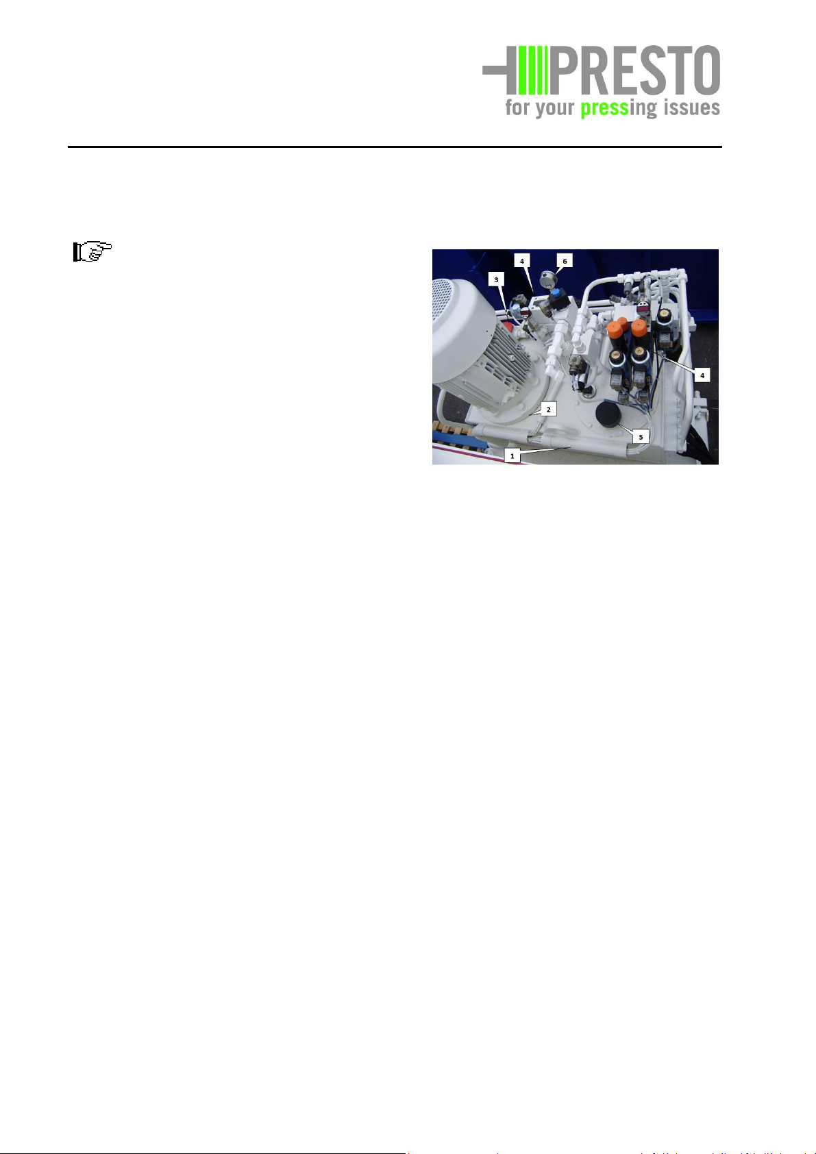
(1) aggregate (hydraulic part)consisting of
the hydraulic pump in the hydraulic tank (2)
and filter unit (3 ), valve block (4) ,
exhauster (5), pressure gauge (6).
The electrically driven hydraulic pump, gear
pump design, provides the hydraulic unit with
the required operating pressure. A valve has
been installed as an overload protection which
protects the hydraulic unit against excessive
pressure.
04/2012 5 - 4
Page 28
PRESTO
GmbH & Co. KG
Bad Laer
• Switch - lack of oil/temperature (9).
Switch-lack of oil
• Two hydraulic cylinders (7),
• Hydraulic lines (10),
• Temperature display (8) – optional
8
The hydraulic pump of the aggregate cannot
be illustrated because it is positioned in the
hydraulic tank.
04/2012 5 - 5
Page 29
PRESTO
GmbH & Co. KG
Bad Laer
5.5. Electrical unit
The electrical works may be
carried out by an authorised
qualified electrician only!
Bauseitige Voraussetzung zur Installation der
Kanalballenpresse ist 400V und 50 Hz.
Type CC-13
Anschluss 3L, PE, 400 V, 50 Hz,
5,5 kW, Drehstrom
Netzanschlussleitung 4 x 2,5 mm2
Gummischlauchleitun
g
FI-Schutzschalter: 30 mA
Vorsicherung: 16 A, träge Sicherung
nach DIN 49462/63
Type CC-20
Anschluss 3L, PE, 400 V, 50 Hz,
7,5 kW, Drehstrom
Netzanschlussleitung 4 x 6 mm2
Type CC-40
Anschluss 3L, PE, 400 V, 50 Hz,
15 kW, Drehstrom
Netzanschlussleitung 4 x 10 mm2
FI-Schutzschalter: 30 mA
Vorsicherung: 35 A, träge Sicherung
nach DIN 49462/63
The a.m. fuse protection and FI-switches
must be observed even if larger plugs with
adapters are used.
Attention!
It is absolutely necessary to
ensure the correct rotation
of the electric motor. A
short time reverse run will
destroy the hydraulic pump.
The motor is running correctly when the
ventilator wheel at the electric motor rotates
in the direction of the arrow on the housing.
As the pump runs without oil flow in case of
wrong rotation, the motor may only be
FI-Schutzschalter: 30 mA
Vorsicherung: 32 A, träge Sicherung
nach DIN 49462/63
Type CC-30
turned on for a very short time (5 seconds as
a maximum).
The assembly "Electrical unit" controls the
machine and supplies it with electrical
energy.
Anschluss 3L, PE, 400 V, 50 Hz,
11 kW, Drehstrom
Netzanschlussleitung 4 x 10 mm2
FI-Schutzschalter: 30 mA
Vorsicherung: 35 A, träge Sicherung
nach DIN 49462/63
04/2012 5 - 6
Page 30
PRESTO
GmbH & Co. KG
Bad Laer
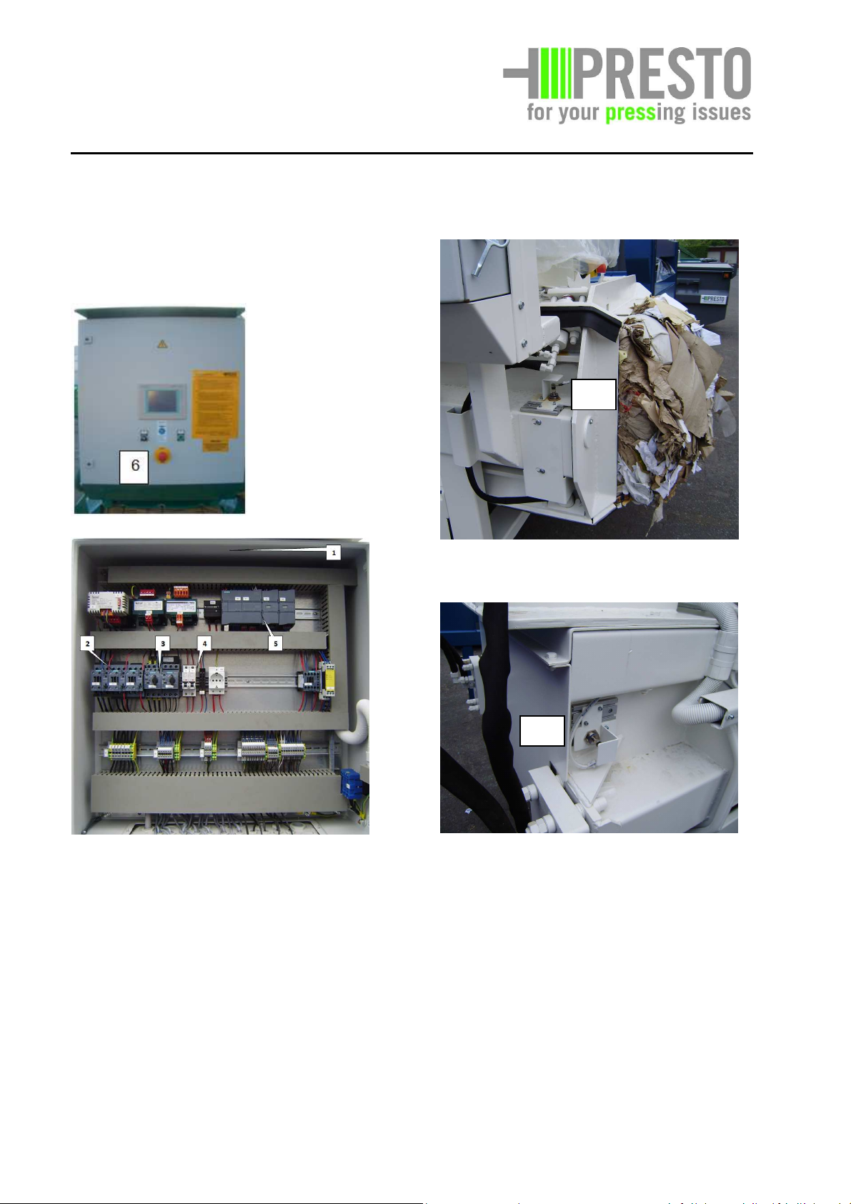
• Switch box (1) with relay (2) motor
protection switch (3), fuses (4) and
operating elements, stored program
control (5) and wiring,
B33
• Limit switch, press in front (B33)
B31
• Limit switch, press backwards (B31)
See fig. “Overview limit switches”, page 5-8
04/2012 5 - 7
Page 31

PRESTO
View from the right sight of the machine
View
from the
lef
t sight of the machine
GmbH & Co. KG
Bad Laer
Overview limit switches
B30 Puls generator bale length
B31 Stop position press backwards
B33 Stop position press in front
B34 Stop position needle down
(left side)
B35 Stop position needle down
(right side)
B36 Stop position needle up
B37 Puls generator drill
04/2012 5 - 8
Page 32

PRESTO
GmbH & Co. KG
Bad Laer
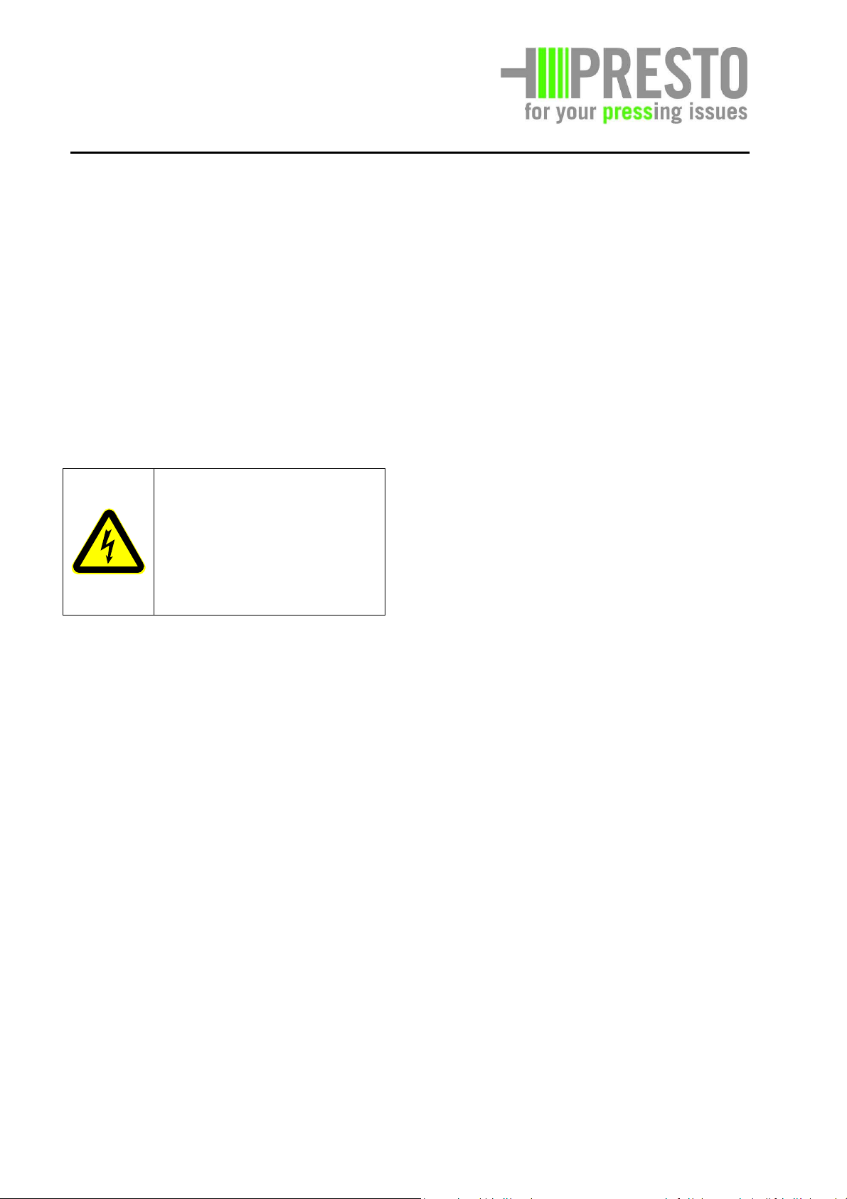
5.6. Tie-off device
5.6.1. Fully automaticl tie-off device
The assembly of the manual tie-off device
consists of the following components:
• Pulse generator (B37), drill
Drill and cutting device (15),
• Pulse generator (B30), bale length
• measuring wheel bale length (16)
See fig. “Overview limit switches” page 5-8
You will find information with regard to
maintenance and care in chapter 7.
Limit switch for needle down, operation
(B35),
limit switch for needle up (B36)
See fig. “Overview limit switches” page 5-8
04/2012 5 - 9
Page 33

PRESTO
GmbH & Co. KG
Bad Laer
If the desired bale length has been achieved
the compressing die will stop in the front final
position. The drilling discs make a half way
rotation and transport the upper wire in one
opening. The lower wire is led from the needle
as a loop upward and laid into the free opening
of the drilling disc (⇒). After a number of
rotations of the drilling disc the drilling process
is finished with a return rotation and the
subsequent cutting.
Drilling disc
You will find the detailed description with
regard to the operation and the sequence of
the tie-off process in chapter 6 "Operation".
04/2012 5 - 10
Page 34

PRESTO
25
GmbH & Co. KG
Bad Laer
The assembly mainly consists of the following
5.7. Attachable funnel with safety
circuit
Attention, danger of
crushing!
Do not climb or reach into
loading opening!
Danger!
This assembly is responsible to observe the
minimum safety height of the loading opening
of 1100 mm above the loading level. The
attachable funnel becomes necessary, if the
channel-type baling press is loaded by means
of a ramp.
components
• Charging funnel with installation
material,
• Light barrier (see chapter 11 "Appendix,
special equipment")
• Safety switch.
PRESTO will adapt the attachable funnel to
the local conditions. As a rule the channeltype baling press and the attachable funnel
have to be installed at the customer's
according to the enclosed project plans.
Attention!
The installation of the funnel
may be carried out be
S2
specialists only!
You will find further information in chapter
11, "Appendix / special equipment"
(A standard funnel with revision door (25) and
safety switch (S2) is shown.
04/2012 5 - 11
Page 35

PRESTO
GmbH & Co. KG
Bad Laer
6. Operating elements and operation
6.2. Operating elements
6.1. General
The channel-type baling press has left our
plant ready for operation. Please check
stationary compression unit for damages by
visual inspection and function test and
inform your forwarding agent immediately
about possible complaints.
Works at/with the unit may
only be carried out by
instructed, reliable staff
and/or by experts.
In general the function and operation of all
types of channel-type baling presses is
similar. There are, however, differences with
regard to the pressing power. This results in
considerable differences in the control and
work sequence.
Prior to the commissioning make sure what
kind of channel-type baling press you use
(see type plate and chapter 4 "Technical
data").
Any accessories, which form part of the
special equipment, are described in the
following point. You will find a more detailed
description with regard to this extra
equipment in chapter 11 "Appendix, special
equipment."
This section describes the operating
elements of the channel-type baling press
CC-13, CC-20, CC-30 and CC-40 with fully
automatic tie-off device.
With respect to all types of channel-type
baling presses the essential operating
elements necessary for the operation are
located centrally in the switch box. If
applicable there might be a Button bar in the
rear area of the unit.
Switch box for channel-type baling press
Type CC-13V, CC-20V, CC-30V and
CC-40V
>> fully automatic tie-off device <<
1. Main switch
2. "Start" Button
3. Illuminated switch "Operation"
4. "Emergency-off" switch
5. Button "Press forward"
6. Button "Press backward"
7. Button "Needle up"
8. Button "Needle down"
9. Selector switch "Twisting"
10. Selector switch "Cutting"
04/2012 6 - 1
Page 36

PRESTO
GmbH & Co. KG
Bad Laer
6.3. Works prior to initial commissioning
You will find information with regard to
transport and loading in section 6.6
"Transport and loading".
First check the unit for completeness of
supplied parts. Use the enclosed shipping
documents for this purpose.
The unit may be erected by
qualified staff with the
corresponding specialized
knowledge only (Explanation
see chapter 7, page 1).
Project documentation and wiring diagrams
of the manufacturer are enclosed to the unit.
The unit has to be installed and connected
according to these plans.
Place unit on a plain base. The base must be
capable of bearing the unit permanently. It
must be possible to screw the legs of the unit
with the base. In order to fix the unit you
should use heavy-duty dowels and
corresponding screws (see enclosed project
documentation).
For detailed description of adjustment
possibilities of the touch panel see page
6-11.
Leave sufficient space around the machine as
shunting area for industrial trucks.
Screw the sheet, i.e. the "bale slide" (50)
contained in the scope of supply with the
bottom side of the channel
(see fig. page 6-3).
04/2012 6 - 2
Page 37

PRESTO
GmbH & Co. KG
Bad Laer
In case of fire in the switch box
only use fire extinguishers
permitted for this purpose. NO
WATER!
Prior to the initial
commissioning the
operator of the unit must
have read and understood
A qualified electrician has to
provide and to check the
correct electrical connection.
Doing this the relevant VDE
regulations and/or the
regulations of the country
where the unit will be used
have to be observed.
Furthermore the wiring
diagrams of PRESTO have to be
observed.
When erecting and taking the unit into
operation the guidelines of the
environmental protection law and the water
household law have to be adhered to.
Carry out the following checks now:
• See to it that it is not possible to damage
the mains connection by running over,
crushing or dragging.
• check all hydraulic lines and screwing for
tight fit and obvious damages..
• Check whether all screwed connections
were properly tightened.
• Check the electric installation.
• Check function of all protective devices
(see chapter 7). Never bring into
commission without all security devices
working perfectly.
Carry out the following works every day
before taking the unit into operation:
• Visual inspection for obvious damages at
mechanical or electrical components. It is
prohibited to take the unit into operation
if one protective device does not work
properly.
• Check the protective devices in chapter 7
for correct function.
• In case of strong pollution the unit has to
be cleaned. Prior to cleaning put main
switch into "0" position and secure with a
padlock against unauthorised
intervention. Close and lock all protective
covers or doors or inspection flaps after
the cleaning.
• Check whether there is sufficient binding
wire on the coils.
• All further regular works have to be
carried out according to the maintenance
plan.
the operating
instructions.
It is possible to stop the
unit immediately in case
of danger by pressing the
emergency-off switches.
04/2012 6 - 3
Page 38

PRESTO
GmbH & Co. KG
Bad Laer
6.4. Compacting process
Attention! Danger of
crushing!
Never climb into charging
opening while the channel-
type baling press is in
operation.
Operation mode "Manual"
This operation mode is normally intended for
maintenance and repair works.
The unit is ready to use, i.e. the safety switch
is unlocked, the covers are closed.
Ensure that no persons are endangered.
• Switch on main switch, press button
operation, light “operation” is lighting.
• Put operation mode selector switch into
"Manual" position
• Press "Start" Button, the hydraulic pump
starts up.
• Move selector switch "Press
forward/back" into desired direction and
keep as long as the press is to be moved.
When running forward care has to be taken
that in the front final position there is not
cut-off by the limit switch. Observe the
pressure gauge. If the press is drawn back
manually the rear limit switch cuts off the
valve automatically when having reached the
limit switch.
Operation mode "Auto"
See to it that no persons are
endangered by the operation
of the unit!
For the fully automatic tie-off device you
should use coiled binding wire. In order to
safeguard a proper function you should use
binding wire which you can acquire through
our service department.
Properties:
• Binding wire for CC-13V and CC-20V on a
20 kg-coil, patent coiling, 2.8 mm
diameter, close annealed and oiled.
• Binding wire for CC-30V and CC-40 on 40
kg-coil patent coiling, 3.1 mm diameter,
close annealed and unoiled.
04/2012 6 - 4
Page 39

PRESTO
GmbH & Co. KG
Bad Laer
• The length of the bale permanently
Note:
Always use binding wire with the a.m.
properties. Binding wire that does not
increases. It is continuously collected by
the pulse generator and indicated.
correspond to the specification may lead to
trouble in the work sequence. You will find
the part numbers in chapter 10, spare parts.
• Throw the material into the charging
funnel. Fill the shaft up to slightly above
the counter knife.
6.4.1 Operation mode "Manual"
General
The manual operation modes
described in the following
assume that the operation
Make sure that no pressing strokes are
effected if the filled in material is not slightly
above the counter knife.
• Check whether there is sufficient binding
wire on the coils.
• Put operation mode selector in "Auto"
position.
• Switch on main switch, press "Operation"
key. The flashing of the control lamp
indicates the readiness for operation of
the unit.
• Press "Start" key (4). The unit starts up
and starts compressing.
• If the funnel has been filled up with
sufficient material and the compressing
die is in its end position, the machine
starts automatically via the installed light
• Switch on main switch, press button
operation, light “operation” is lighting.
• Put operation mode selector switch into
"Manual" position
• Press "Start" Button, the hydraulic pump
starts up.
• Move selector switch "Press
forward/back" into desired direction and
keep as long as the press is to be moved.
mode selector switch is put in
"Manual" position. The
operation mode "Manual"
has to be used for the
threading of a new binding
wire and for maintenance,
repair and adjustment works.
barrier.
The unit will check after the start
whether the compressing die is in the
rear position. The compressing die returns to
the back limit position and the pump is
switched off.
04/2012 6 - 5
Page 40

PRESTO
GmbH & Co. KG
Bad Laer
Needle upward / downwards
Condition: The final limit switch (B33)
"Press in front" is actuated. This is the case
when the compressing die is in the front final
position.
Needle from the "operating position" to
"threading position"
Conditions: The needles are in the basic
position, i.e. the limit switches "needle at the
bottom" (B34/B35) are actuated. The
compressing die is in the rear limit position,
i.e. the limit switch (B31) "Press at the rear"
is actuated.
B33
• Press key "Needle up" and hold. The
valve for” Needle up” is switched on as
long as the key is pressed.
The needle runs through the
compressing die upward until the limit switch
"needle up" (B36) switches. If the hydraulic
cylinder for the needle has fully extended and
if the switch is further kept in "needle
upward" position the pressure at the
hydraulic cylinder will increase to the
maximum pressure of 130bar.
Needle down
• Press key "Needle up" (7a) and hold.
The needle moves downward until the
limit switches "needle at the bottom" switch.
B31
• Press key (7b) "Needle down". This
process takes about two seconds.
The needle moves into the lowest
position, i.e. up to the limit stop. The
threading position has been reached. The
compressing die cannot be moved now. A
new lower wire can be threaded in now.
04/2012 6 - 6
Page 41

PRESTO
GmbH & Co. KG
Bad Laer
eading position" to
"operating position"
Twisting
• Press key "Twisting" (8a) and hold.
Conditions: The needles are in threading
position, i.e. the limit switches "needle at
the bottom" (B35) are not actuated. The limit
switch “Needle in threading position” (B34) is
actuated. The compressing die is in the rear
limit position, i.e. the limit switch (B31)
“press at the rear" is actuated.
• Press key (7b) "Needle up".
The drilling disc carries out a half
rotation. The pulse generator simultaneously
switches "Drill" (B37). Thereby the wires are
not cut.
Cutting
• Press key "Cutting" (8b) and hold.
The needle drives forward up to the
limit switch "needle at the bottom"
(B34/B35). The needle is in basic position.
The compressing die can be moved again.
The drilling disc carries out a half
rotation anticlockwise when drilling. The
cutting-off will not yet be made. The cuttingoff is possible when the cutting-off device is
held by the stop. The wires are cut off after a
new actuation of the key "Cutting" and a half
rotation of the drilling discs.
04/2012 6 - 7
Page 42

PRESTO
GmbH & Co. KG
Bad Laer
Visible only right side of the machine
04/2012 6 - 8
Page 43

PRESTO
GmbH & Co. KG
Bad Laer
Adjustment of pressing power
As a standard design the unit of CC13V and
CC20V are supplied with manual channel
adjustment. Optionally a hydraulic channel
adjustment with control can be supplied. You
will find the description of the hydraulic
channel adjustment in chapter 11.
The pressing power depends on the
backpressure of the material in the channel.
In order to achieve this back pressure the
cross section in the direction of the channel
outlet becomes smaller.
The back pressure of the material depends
on the following factors:
• Coefficient of friction of the channel walls
which slightly reduces after the runningin period of the unit,
• Coefficient of friction of the material to
be compacted. This can vary very strongly
(e.g. relatively high with respect to
cardboard and relatively low in case of
foils),
• The fill height in the fill in funnels by the
start of the press procedure. The fill in
funnels must be filled up to the upper
edge of the press body with material at
least, so that the channel discharge is
filled evenly.
• Adjustment of the tensioning elements
(10) on both sides of channel outlet
which must be changed especially during
the running-in period and in case of
material change.
The adjustment is correct if during the
forward stroke phase approx. 140 - 160 bar
are indicated at the pressure gauge. For this
reason the pressure gauge has to be
observed as a rule after material changes.
04/2012 6 - 9
Page 44

PRESTO
GmbH & Co. KG
Bad Laer
Attention!
Never fall short of the measurement of 65
mm (the spring package is almost completely
pressed together).
04/2012 6 - 10
Page 45

PRESTO
GmbH & Co. KG
Bad Laer
Adjusting the compaction pressure
hydraulically
The compaction pressure depends on the
counter-pressure of the material in the
channel. To achieve this counter-pressure,
the channel is narrowed by means of 4
hydraulic cylinders.
The counter-pressure of the material
depends on the following factors:
• Coefficient of friction of the channel
walls, which decreases slightly during the
plant running-in period;
• Coefficient of friction of the material to
be compacted, which varies highly (e.g. it
may be relatively high for cardboard
packaging and relatively low for plastic
films).
• The fill height in the fill in funnels by the
start of the press procedure. The fill in
funnels must be filled up to the upper
edge of the press body with material at
least, so that the channel discharge is
filled evenly.
6.4.2.1 Adjust bale length, twist
The unit must be switched on
during these adjustment
works. Therefore ensure that
no persons are endangered
during your activities. Visibly
fix a sign in order to point to
the adjustment works. Any
other procedure will be
pointed out extra.
Adjusting bale length (8)
Factory adjustment: 20
Potential range of adjustment:
13 counting pulses = about 0.65m
50 counting pulses = about 2.5m
(One counting pulse corresponds to about
0.05m)
If you want an adjustment that differs from
the factory value, proceed as follows:
04/2012 6 - 11
Page 46

PRESTO
GmbH & Co. KG
Bad Laer
6.5
Control- and programdiscription
Options
Main menu
Fig. 1: Main menu
Navigation and adjustments with Touch
Panel
With the button „Menu“ in the starting
picture you get to the window „main menu“.
In the main menu of the press different
menu entries can be chosen, e.g. show
„machine-data“. Adjustments can be edited
after entering a password in the menu entry
„settings“ (see “Settings”).
Key assignment in main menu:
F1-> display help
F2-> user login
F3-> language choice
F4-> show message buffer
F5-> lamp test
F6-> standard picture press
Fig. 2: Options
Pressing the button „Options“ the window
will open. Additional control and display for
the control of the conveyor (if existent) can
be found here.
A pre-selector for the limit position
disconnection of the compactor decides
whether the ram stops in front or rear
position after pressing.
Machine Data
Fig. 3: Machine data
Following menu entries can be found in
„machine-data“: bale counter, daily bale
counter and the graphics of the pressure at
the moment (shown in “bar”). The bale
counter indicates the total sum of wired
bales. The daily bale counter counts the
bales and can be reset to “0” after entering
the password.
04/2012 6 - 12
Page 47

PRESTO
GmbH & Co. KG
Bad Laer
Pre-selection pressure level
Menu Settings
Fig. 4: Preselection pressure level
With menu entry „pre-selection pressure
level“ the desired pressure level for the
material can be chosen. The values for the
different pressure levels are edited
separately in the menu „settings“.
Language choice
Fig. 5: Language choice
The menu entry „Language choice“ can be
activated out of the main menu or settings
menu.
Fig. 6: Settings
Via „main menu“ you get into the menu
entry „settings“ after entering the „User“
password (see entering password).
With the suitable function key you reach
further settings such as „time setting“ and
„system settings“. „System settings “ are
protected with a „PRESTO“ password (*see
entering of password).
Key assignment
„Settings“:
F1-> display help
F2-> login user
F3-> language choice
F4-> time settings
F5-> system settings
F6-> main menu
04/2012 6 - 13
Page 48

PRESTO
GmbH & Co. KG
Bad Laer
Entering the password
Setting of material pressure levels
Fig.: Entering the password
Some of the menus and functions are
secured with a password. Whenever a
password is needed, a window opens to
enter the password. Authorization is effected
by login of the user and the password.
Basically there are two levels of passwords.
First the „USER“ password level which is for
the operator and secures operation of the
press as well as settings of modification by
unauthorized persons. The second password
level „PRESTO“ secures system settings of
modifications by unauthorized persons and is
intended for the service technicians.
To login user and password the entry field of
the login screen has to be actuated (see fig.
password inquiry). The password or the user
name can now be entered with the touch
screen and has to be confirmed with enter
(fig.: entering password). The USER password
is „100“.
Next the user name and the password have
to be confirmed with the button „OK“ (see
fig.: Password inquiry). If the password is
correct the user has access to all
corresponding menu entries and functions.
Unless an error message appears.
Fig.: Pressure level „High“
Fig.: Pressure level „Middle“
Fig.: Pressure level „Low“
The values have to be set separately with the
corresponding buttons in the menu “settings.
Following pressure stages according to the
material:
Pressure level „High“ = Material: corrugated
board, paper, cardboard or similar.
Pressure level „Middle“ = Material: PET, PETbottles or similar.
Pressure level „Low“ = Material: Foil or
similar.
04/2012 6 - 14
Page 49

PRESTO
System
time
Input fields
GmbH & Co. KG
Bad Laer
Following values can be set:
Bale length 13 – 50 (1 = ca. 5-
6 cm.)
Half twist turnings 11 – 18 (1 = ½
twists)
Half backstroke in sec. 4 – 20 sec.
Relief pressure „nominal“ in
bar
Channelpressure „nominal“
in bar
10 – 260 bar
10 – 250 bar
System settings
Button „View right/left“
(press to choose)
Shut down
Touch Panel
Time setting
Button „Entering Input“ (press
longer than 1 sec.)
Whenever the time set does not correspond
to the actual time, time and date can be
changed via menu entry „time setting“..
Button „funnel door
yes/no“ (press to
choose)
Contrast
regulation
System settings include internal settings of
the touch panel and can only be modified
from our service technicians (fig.: system
settings).
04/2012 6 - 15
Page 50

PRESTO
Threading position
Operating position
Threading example for the lower wire for CCV
GmbH & Co. KG
Bad Laer
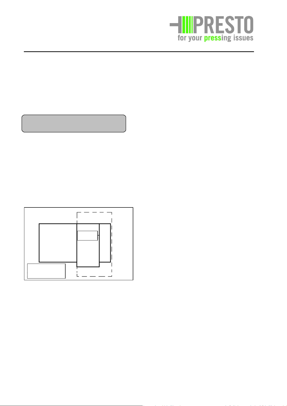
6.6 Insert binding wire coils
Inserting the lower wire
Loading the wire containers or the large roller stations with wire.
Master switch ON (13)
Selector switch to „Manual“ (8)
Press Operation button (9). System is ready for operation.
Press Start button (1). Electrical motor and hydraulic pump (20) are running.
Pressing ram backwards (button 3b). Press and hold button “ram backwards”. Ram
moves backwards until end position (B31) is reached and valve is closed.
Needle in threading position: Pressing ram must be completely retracted; press the
Needle down button (4b). Needle moves down and stops in Threading position
(only B34).
Pulling in the wire Straight align the wire and pull in.
1 through the spring winding at the end of the press
2 through the drill bushes at the rear support legs
3 through the needle profile above the needle head
4 pull wire through to the end of the channel
04/2012 6 - 16
Page 51

PRESTO
2
3
4 1
wheel
GmbH & Co. KG
Bad Laer
Retract needle to operating position. Pressing ram is retracted (rear). Press and hold the
Needle up button (4a). Needle moves up and stops in the Operating position (B34 + B35).
Inserting the upper wire
a) Pull the wire through the wire deflection pulley as shown below. Push the wire as far
as possible through the opening in the press shaft
b) Close all doors/covers
c) Select Automatic operating mode (8)
d) Press Operation button (9).
e) Perform approximately 2 – 3 press operations with the material until the upper wire
is tight.
f) During the subsequent extension of the pressing ram, rotate the bale length wheel
(B30) until Binding is indicated on the Touch panel (or if existent the light signal
Binding flashes).
Bale length
Binding signal
04/2012 6 - 17
Page 52

PRESTO
GmbH & Co. KG
Bad Laer
Once the binding process is completed, check the quality of the connection of the upper
and lower wire above the knotting device; make some improvements, if necessary (the
pre-tensioning of the wire, which occurs during normal operation, has not been applied
yet)
Good knot
Knot too loose
The processes 12 and 13 have to be carried out together at least twice with the
operating personnel.
04/2012 6 - 18
Page 53

PRESTO
GmbH & Co. KG
Bad Laer
6.7 Transport and loading
Before the transport and loading work take
place the following accident prevention rules
have to be adhered to:
BGV D8 Gear, lift- and draft devices
BGV D6 Load bearing facilities
BGV D27 Ground conveyors
BGV D29 Motor vehicles
BGV A8 Safety labelling at the
workplace
Remove transport safety devices and
handling systems
See to it that no persons
stay under the suspended
load.
Connect unit to the mains before taking the
unit into operation again.
Use corresponding lifting devices and proper
securing measures (for information
concerning the maximum permissible weight
see type plate or chapter 4 "Technical data"
in these operating instructions).
Lift device at the intended
lifting points only. Secure
load against unintended
changes of the position.
Separate unit from every external energy
supply also in cases of a slight change of the
position!
Parts that are removed for transport
purposes have to be mounted and fixed
before taking the unit into operation again!
04/2012 6 - 19
Page 54

PRESTO
GmbH & Co. KG
Bad Laer
Using a forklift truck
Adhere to accident prevention rules BGV D27
and D29. Empty the unit completely.
• Separate unit from mains and place
supply cable on the unit bound together.
• Disassemble all projecting parts or lead
the tie-up material over such parts.
• Only drive under bearing frame parts
with forks (directly under machine
housing), never drive under needle
guide and/or hydraulic cylinder.
Example: CC 30, Points of notice forks
• Tie-up unit on a transport vehicle by
diagonal attachment or make use of the
existing eyes.
• Disassemble all projecting parts at first
and/or do not lead tie-up material over
such parts.
Lift machine at intended loading point only
or use forks of forklift truck only at bearing
parts! See schematic view!
The forks only in places marked by the
Following sign set.
Example: CC 40, Points of notice forks
04/2012 6 - 20
Page 55

PRESTO
GmbH & Co. KG
Bad Laer
7. Maintenance
As a rule it is recommended to conclude a
maintenance agreement with PRESTO. The
maintenance will be carried out twice a year
by our service department. Because of the
special knowledge of our service mechanics
sources of trouble are found in time and can
be corrected.
Attention!
Safety equipment for the
prevention or elimination of
hazards must be maintained
at regular intervals
according to § 39(3), BGV A1
- General regulations and
must be checked with
respect to their proper
function at least once per
month by a qualified person.
A qualified person is
someone who on the basis
of his special training has
sufficient knowledge in the
field of the used machine.
Furthermore the qualified
person must be familiar with
the relevant on-the-job-
safety provisions, accident
prevention rules, guidelines
and generally accepted
technical rules to such an
extent that he/she can judge
7.1. General
Safety covers held in place by bolts which fit
through keyhole-shaped slots are removed
from the machine by loosening the bolts 3 or
4 turns. The bolts should remain in the drill
holes. The cover can now be slid along the
keyhole and removed by lifting over the bolt
heads which fit through the round, upper
keyhole aperture. The covers are replaced by
reversing the sequence.
For a better presentation
we have left away the
protective covers in some
illustrations. The channeltype baling press may be
taken into operation with
properly fixed or closed
protective covers only.
In case of maintenance and repair works the
machine has to be cut off completely and be
secured against unauthorised reclosing.
Danger!
Staying in the danger zone is only permitted
during specially described works for
correspondingly instructed personnel
and/or qualified experts whereby the safety
instructions have to be adhered to.
ATTENTION!
All works, such as commissioning,
maintenance and repairs may be carried out
by qualified personnel only and/or have to
be controlled by responsible experts.
the safe condition of the
used machine.
For channel-type baling presses which are
operated outside of the application area, the
existing regulations and guidelines of the
user country will be valid.
04/2012 7 - 1
Page 56

PRESTO
GmbH & Co. KG
Bad Laer
The operator of the unit has to notify his
superior as soon as possible about any
occurring trouble or irregularity. The same
applies for mechanical and electrical
equipment.
See to it, that the operating instructions
belonging to the channel-type baling press,
the maintenance and special tools and
devices, the oil cans and grease guns
required for lubrication is always kept in the
provided receptacles.
When dealing with oils, greases and other
substances the specific safety regulations
and legal provisions which are valid for the
product have to be observed!
Observe adjustment and maintenance works
7.2. Cleaning
Properly clean the unit weekly or in case of
excessive pollution.
Cut off electrical current
prior to starting the
cleaning.
Put main switch (1) in "0" position, pull out
yellow safety bow and secure with a padlock.
Do not direct water nozzle directly to
electrical components, bearing- and
lubrication points.
Inspect and clean the area (1) behind the
press body.
described in the operating instructions
including information for the replacement of
parts/partial equipment!
These works may be carried out by qualified
persons with sufficient knowledge and
corresponding tools.
Danger of injury! Before
carrying out any cleaning
and maintenance work,
always check the area for
foreign matter such as
sharp-edged material, one-
way injection needles etc.
Inspect and clean the hollow spaces on both
sides in which the lateral beams of the press
body are immersing.
Also check whether
contaminated materials
have been compacted.
Contact the operators before if required.
Non-compliance may cause severe health
problems.
04/2012 7 - 2
Page 57

PRESTO
GmbH & Co. KG
Bad Laer
Be sure to check the guide grooves of the
telescopic plates once a month for blockage
or
material accumulation and eliminate if
necessary.
Meaning of the abbreviations:
= works, that can be carried out by
the operator of the machine
= works that have to be carried out
7.3. Maintenance
by an expert (e.g. PRESTO service
mechanic)
7.3.1. Maintenance schedule
On the following pages you will find a list of
the maintenance works with information
with respect to the maintenance interval and
reference to the description of the work.
The maintenance of electrical equipment
Abbreviation for the intervals:
T daily
W weekly
M monthly
H every six months
J annually
may be carried out by experts or instructed
persons only.
04/2012 7 - 3
Page 58

PRESTO
GmbH & Co. KG
Bad Laer
Electrical system Interval Page Resp.
person
Controls on the switch cabinet and control bar: function check T A
Main switch and Emergency OFF switch: function check T 7-17 A
Motor protection relay: function check J 7-14 F
Wiring in the switch cabinet and on machine housing: visual check J 7-10 F
Power cable: visual check W 7-10 A
Safety switch on side service doors, needle hatches: function check T 7-9 A
Safety switch on twister hood: function check T 7-9 A
Safety switch on service door in the hopper: function check T 7-8 A
Terminal position switch for emergency pull line (optional): function check W A
Ventilation hood on electrical motor: check for cleanliness T A
Automatic start system (optional): check function and cleanliness W A
Hydraulic system
Hydraulic aggregate and fittings: check condition and tightness H A
Hydraulic oil: check condition and oil level and refill if necessary M 7-11 A
Filter insert and ventilation filter: replace J F
Hydraulic hoses and fittings: check condition and tightness H A
Hydraulic lines and fittings: check condition and tightness H 7-15 A
Hydraulic valves: check tightness H A
Hydraulic cylinder (main, needle, twister, channel): check tightness and condition H 7-16 A
Compaction pressure: check setting acc. to specification J F
Other hydraulic accessories: check function and tightness H A
Oil change J 7-17 F
Mechanical system
Plunger: check condition and wear J F
Plunger setting in channel: check and adjust if necessary M A
Polyamide guides on plunger: check for wear M 7-14 A
Telescoping sheets: check the condition J F
Polyamide telescoping sheet guides: check condition and wear M 7-14 A
Cutting gap on the plunger: check and adjust if necessary W 7-12 A
Counter-blade and blade on the plunger: check condition and wear W 7-18 A
Compaction channel floor: check condition and wear J F
Needle guide rollers: check cleanliness and wear W A
Needle head: check condition and wear M A
Binding system: check function and cleanliness T A
Twister disks: check the setting T 7-13 A
Twister chain: check the condition, lubricate, adjust and re-tension if necessary M 7-13 A
Twister blade: check wear and movability W A
Polyamides in the twister: check for wear J F
Retainer: check function W 7-19 A
Locking pins on hydraulic cylinder: check wear and lubricate J F
Press bar on channel outlet: check the securing pin W A
Guides for binding wire and binding strap: check free run W A
PVC cover on channel outlet: check the condition H A
Service doors, twister hood, service and cleaning hatches: lubricate J F
Moving parts on compactor: check movability and lubricate J F
Ground anchors of the compactor: check firm seat J F
Service doors, protection hoods and cover panels: check the condition M A
Hopper: check the condition J F
Overall condition of the compactor's welded construction: check the condition J F
Bolted connections in general: check for firmness T 7-7 A
Labels: check condition and legibility H A
Overall condition of the machine's welded construction: visual check W A
Other accessories (optional): check condition and function W 7-10 A
Note:
Maintenance works, as far as they concern special equipment, are described in chapter 11 "Appendix, special equipment".
04/2012 7 - 4
Page 59

PRESTO
GmbH & Co. KG
Bad Laer
This page shows a table where all work of the previous page is listed again. Copy this list as often as
required and keep records about the work carried out.
Result of maintenance carried out on: _____________________ by:__________________
Electrical system
Controls on the switch cabinet and control bar: function check
Main switch and Emergency OFF switch: function check
Motor protection relay: function check
Wiring in the switch cabinet and on machine housing: visual check
Power cable: visual check
Safety switch on side service doors, needle hatches: function check
Safety switch on twister hood: function check
Safety switch on service door in the hopper: function check
Terminal position switch for emergency pull line (optional): function check
Ventilation hood on electrical motor: check for cleanliness
Automatic start system (optional): check function and cleanliness
Hydraulic system
Hydraulic aggregate and fittings: check condition and tightness
Hydraulic oil: check condition and oil level and refill if necessary
Filter insert and ventilation filter: replace
Hydraulic hoses and fittings: check condition and tightness
Hydraulic lines and fittings: check condition and tightness
Hydraulic valves: check tightness
Hydraulic cylinder (main, needle, twister, channel): check tightness and condition
Compaction pressure: check setting acc. to specification
Other hydraulic accessories: check function and tightness
Oil change
Mechanical system
Plunger: check condition and wear
Plunger setting in channel: check and adjust if necessary
Polyamide guides on plunger: check for wear
Telescoping sheets: check the condition
Polyamide telescoping sheet guides: check condition and wear
Cutting gap on the plunger: check and adjust if necessary
Counter-blade and blade on the plunger: check condition and wear
Compaction channel floor: check condition and wear
Needle guide rollers: check cleanliness and wear
Needle head: check condition and wear
Binding system: check function and cleanliness
Twister disks: check the setting
Twister chain: check the condition, lubricate, adjust and re-tension if necessary
Twister blade: check wear and movability
Polyamides in the twister: check for wear
Retainer: check function
Locking pins on hydraulic cylinder: check wear and lubricate
Press bar on channel outlet: check the securing pin
Guides for binding wire and binding strap: check free run
PVC cover on channel outlet: check the condition
Service doors, twister hood, service and cleaning hatches: lubricate
Moving parts on compactor: check movability and lubricate
Ground anchors of the compactor: check firm seat
Service doors, protection hoods and cover panels: check the condition
Hopper: check the condition
Overall condition of the compactor's welded construction: check the condition
Bolted connections in general: check for firmness
Labels: check condition and legibility
Overall condition of the machine's welded construction: visual check
Other accessories (optional): check condition and function
04/2012 7 - 5
Page 60

PRESTO
GmbH & Co. KG
Bad Laer
Emergency-off switch, check function
7.3.2. Description of the
maintenance works
The stated maintenance intervals have to be
understood as standard values which apply
under normal operating conditions. In case
of extreme conditions as e.g. high humidity,
aggressive atmosphere, temperature
fluctuations etc. the maintenance intervals
have to be shortened if required. Please
contact the PRESTO service department in
this regard.
The unit has to be
switched off completely in
case of maintenance and
repair works and be
secured against
unauthorised reclosure. In
case of other procedures
this will be especially
pointed out.
• Press emergency-off switch (2). The key
must click into place in this position.
• Put main switch (1) in "I" position.
• Put operation mode switch (3) in "Auto"
position
• Press key "Operation" (4)
• Press "Start" (5) key in order to check the
proper function of the emergency-off
switch
• The function test is ok if the unit does not
start operation.
• After having finished the function test,
put main switch (1) into position "0"
• Pull emergency-off switch and lock into
place noticeably.
If no further maintenance works have to be
carried out in this field, replace removed
protective covers and retighten properly
again.
Safety signs (6), undamaged and legible
Main switch damaged and lockable
• Check whether main switch (1) can be
switched into "0" or "I" positions.
• Put main switch into "0" position and
check whether the yellow safety bow can
be pulled out and clicked into place.
• Check whether the safety signs (signs
with yellow background) are undamaged
and legible.
• Replace the safety sign (6) if it is
damaged or illegible.
04/2012 7 - 6
Page 61

PRESTO
GmbH & Co. KG
Bad Laer
Type plate undamaged and legible
• Check whether type plate (7) is
undamaged and legible.
• Replace the sign if it is damaged or
illegible.
Check safety switch at
charging funnel with respect
to function
• The unit is out of operation at the
beginning of the inspection.
• Open inspection cover (20) of the
charging funnel.
• Put main switch into position "I"
emergency-off pulled and unlocked.
• Put operation mode switch in "Auto"
position.
• Press "operation“ button.
• Press "Start" button in order to test the
proper function of the safety switch (21).
• The function test is ok. if the machine
does not start up.
• Close inspection cover properly after the
function test has been finished.
21
20
04/2012 7 - 7
Page 62

PRESTO
GmbH & Co. KG
Bad Laer
Safety switch, bottom area
• The unit is out of operation at the
beginning of the inspection. For this
inspection you will need a person who
has been instructed in the operation of
this machine and the test sequence prior
to the inspection.
• The second person opens the flap in the
rear area at the bottom side of the unit.
The flap has to be kept open with a metal
pin, e.g. a screwdriver.
Attention! Never use the
hands! Danger of crushing!
Pull cord switch, check function
• The unit is out of operation at the
beginning of the inspection.
• Press the reset button of the pull cord
switch until it clicks into place.
• Now pull the pull cord (23) until you can
hear how the switch clicks into place.
• Put main switch in "I" position,
emergency-off pulled and unlocked.
• Put operation mode selector in "Auto"
position.
• Press "Operation" key.
• Press "Start" key in order to test the
proper function of the pull cord switch
(24).
• The function test is successful if the
machine does not start up.
• Put main switch into position "I",
Emergency- off pulled and unlocked.
• Put operation mode selector in "Auto"
position.
• Press "Operation" key.
• Press start key in order to test the proper
function of safety switch (22)..
• The function test is ok if the machine
does not start up.
• Close the flap after the function test.
Re-establish the condition of the unit in the
same way as prior to this function test.
22
04/2012 7 - 8
Page 63

PRESTO
GmbH & Co. KG
Bad Laer
Inspect area behind press ram and clean as
required
• The function test is successful if the
machine does not start up.
Put main switch in "0"
position and secure with a
padlock prior to this work.
• Take off coils with tie-up material.
• The area can be inspected from the back
(see arrow). Clean this area with a metal
bar if required.
Check function of safety switch of tie-off
device
The unit is out of operation
prior to the inspection! During
the inspection no persons
may stay in the area of the
tie-off device.
• Open the cover (26) of the tie-off device.
• Put main switch in "I" position,
emergency-off pulled and unlocked.
• Put operation mode selector in "Auto"
position.
• Press "Operation" key.
• Press the "Start" key in order to test the
proper function of safety switch (27).
Close the cover to the tie-off device after
having finished the function test.
Current, connection cable, check condition
Check the connection
cable for obvious
damages as e.g.
squeezing, porosity etc.
If damages are found the connection cable
has to be replaced immediately by a qualified
electrician.
04/2012 7 - 9
Page 64

PRESTO
GmbH & Co. KG
Bad Laer
The channel type baling
press must not be taken into
operation if the condition of
the connection cable is not
proper.
Current, plugged connections, check condition
Put main switch in "0"
position before opening the
switch box.
Check hydraulic oil level
• First drive press ram into open limit stop
Prior to the start of this
work put main switch into
"0" position and secure
with a padlock.
• Check the hydraulic part of the aggregate
for tightness (visual inspection).
• Screw out tank ventilator.
• Inspect plugged connections for obvious
damages as e.g. corrosion etc.
• The damaged plugged connections have
to be replaced immediately by a qualified
electrician.
• Check run-in hydraulic cylinders if the
distance between liquid level and upper
edge of the screwed socket is not more
than 4 - 5 cm.
• Refill hydraulic oil as required. You will
find information with regard to the used
hydraulic oil in the section "Operating
fuels, specifications".
• See to cleanness in the area of the tank
ventilator. Retighten tank ventilator.
If no further maintenance works have to be
carried out in this area, replace removed
protective covers again and retighten
properly.
04/2012 7 - 10
Page 65

PRESTO
40
GmbH & Co. KG
Bad Laer
Carry out cutting clearance check
Ex works the cutting clearance is adjusted
less than 1mm. Make sure this value is not
exceeded. A too big cutting clearance or
blunt knives could block the pressing ram in
• Loosen the counter nuts (42) of the
adjusting screws (43) on both sides of the
unit.
Adjusting screw with counter nuts (only right hand
shown)
the worst case. Furthermore it could lead to
damages at the machine casing.
• Run press ram into the direction of the
channel that far that the outer knives of
the pressing die are covered by half of
the counter knife each.
Attention! Danger of
crushing!
Put main switch in "0"
position prior to the
start of the following
works and secure with
a padlock.
• Measure the distance (max. 1.0 mm)
between knives (40) and counter knives
(41) with a feeler gauge.
• First screw in cautiously only one
adjusting screw on each side. This should
preferably be the adjusting screw in the
middle of the screw field.
• Measure cutting clearance again. Repeat
this procedure until the measured cutting
clearance is 0,3 mm +/- 0,1 mm.
• Tighten all other adjusting screws
manually without using any tools. The
adjusting screws have to sit close then.
Use a screwdriver now and screw in all
adjusting screws by approx. 1/6 rotation.
• Retighten counter nuts again.
• Repeat measurement of the cutting
clearance (0,3 mm +/- 0,1 mm).
• Remove possible foreign bodies (e.g.
tools or similar) from the pressing room.
• Check by the aid of a person who has
been instructed in advance the proper
function of the unit. Agree upon a clear
• If the value of 1.0 mm is achieved or
sign for the immediate stop of the unit.
exceeded the cutting clearance has to be
adjusted as follows:
04/2012 7 - 11
Page 66

PRESTO
GmbH & Co. KG
Bad Laer
• Let the press ram run forward or
backward several times in the operation
mode "Manual". See to it that neither
pressure fluctuations can be seen at the
pressure gauge (44) nor seizing marks are
visible at the upper side of the press ram.
Drilling/cutting device, check chain tension
and lubricate chain (in case of fully automatic
only)
Prior to starting with this
work put main switch into
"0" position and secure with
a padlock.
• Open cover in order to make the chain
drive accessible.
• Measure the totally remaining range of
spring of the disk spring package at the
chain tensioner (60). The value may be 5
mm as a maximum. The chain tension has
to be adjusted as required.
• Stop the unit, if the above described
signs occur.
• Repeat adjustment works if necessary.
Prior to starting with the maintenance
works first see to safe working
conditions, see first section of this
maintenance point.
When compressing plastic foil the
cutting clearance has to be as small as
possible. Initial pressures of approx. 150 bar
during the return stroke indicate a jamming
by pulled along foil resulting from an
excessive cutting clearance. A too big cutting
clearance (>2mm) in connection with blunt
cutting edges (edge radius >0,5mm) and
appropriate material behaviour (e.g. foils,
PET o.s.) results in vertical force introductions
into the housing structure which could add a
multiple of the thrust of the pressing ram.
Thus severe damages (cracks, permanent
deformations) can be caused.
60
• Turn the nut clockwise or anti-clockwise
until the measured value is less than 5
mm.
• Provide chain with a commercial quality
chain spray type lubricant on this
occasion.
• Properly close cover again.
04/2012 7 - 12
Page 67

PRESTO
GmbH & Co. KG
Bad Laer
Motor protection relay (50)
Type Setting (A)
CC-13 (4 kW) 9,0 A
CC-20 (7,5 kW) 15,5 A
CC-30 (11 kW) 22 A
CC-40 (15kW) 30A
Check the adjustment according to the
enclosed PRESTO wiring diagrams.
You will find the wiring diagrams and the
adjustment values in chapter 11.4. "Wiring
diagrams".
• Drive press body to rear final position.
• Put main switch into "0" position and
secure with a padlock.
• Apply a thin grease layer if the polyamide
rails develop loud noise.
• Check the polyamide rails (55) of the
telescope sheets and the press body for
obvious damages as e.g. broken out
pieces, cracks etc. Damaged rails have to
be changed!
After having finished the work mount cover
reclosing. If to proceed in another
matter, this will be clearly stated.
sheets again and tighten correctly.
Check fuses and replace if required
Put main switch into "0" position
before you open the switch box.
Remove the defect fuse and replace it by a
new one (F) of the same specification (see
chapter 10, spare parts or chapter 11
Appendix, wiring diagrams).
Check condition of polyamide rails
The machine has to be cut off
completely during maintenance
and repair works and has to be
secured against unauthorised
55
55
04/2012 7 - 13
Page 68

PRESTO
GmbH & Co. KG
Bad Laer
Check condition and tight fit of hydraulic lines
and screwing
Put main switch into "0" position
and secure with a padlock before
you start with this work.
• Check all pipe and hose connections for
tight fit. Retighten if required. This check
has to be carried out for the first time
approximately 4 weeks after the
commissioning of the unit. All further
controls have to be carried out according
to the interval stated in the maintenance
schedule.
• Carry out a visual inspection for obvious
damages on this occasion. Keep an eye
on fabric damages at hoses, damages at
pipes etc.
04/2012 7 - 14
Page 69

PRESTO
GmbH & Co. KG
Bad Laer
Check hydraulic cylinder with regard to
condition and leakage
The machine has to be cut off
completely during
maintenance and repair works
and be secured against
unauthorised reclosing. If to
proceed in another matter,
this will be clearly stated.
Check all hydraulic lines in the area of the
hydraulic cylinder (see arrows) for possible
leakage.
Check all other screwed connections for tight
fit and/or missing parts (without illustration).
Put main switch into "0" position and secure
with a padlock before you start with this
work.
Aggregate, oil change
First drive press body into open final
position.
• Put main switch into "I" position,
emergency-off pulled and unlocked.
• Push "Operation" button.
• Put selector switch in "Manual" position.
• Push the button "Press backwards"; now
the press ram drives to the open limit
position. When having achieved the final
position the press ram is stopped.
Put main switch into "0"
position and secure with a
padlock before you start
with this work.
Prior to draining the oil it must have reached
the operating temperature.
!!! Attention, hot oil.
Danger of scalding!!!
Collect operating fuels (e.g. hydraulic oil) in
appropriate vessels during maintenance
works and discharge according to the (acc. to
EC directive 75/439/EWG and orders acc. to
§§ 5a, 5b AbfG and AltölV).
04/2012 7 - 15
Page 70

PRESTO
GmbH & Co. KG
Bad Laer
• Irrespective of the achieved number of
operating hours an oil change has to be
carried out at least once a year.
• Combine the oil change with a proper
cleaning of the installation area around
the aggregate.
• You will find information with regard to
the hydraulic oil in the section "Operating
fuels, specifications".
• Reinstall the new filter element and the
new ventilation filter.
• Continue with the maintenance point
"Replace filter insert".
• Screw out tank ventilator (60).
• Screw out the sealing cap (61) of
the oil filter and remove the filter
element.
• Pump the waste oil out of the oil
filter opening into an appropriate
vessel.
• Fill new hydraulic oil into the
control opening. The oil level is
correct if the distance between the
liquid level and the upper edge of
the screw in opening does not
amount to more than 4-5 cm.
Oil sight glass
04/2012 7 - 16
Page 71

PRESTO
41
40
40
40
40
GmbH & Co. KG
Bad Laer
Any movable parts not mentioned in the
above list as e.g. hinges, spindles etc. have to
be lubricated at regular intervals. With this
easy care you will preserve the function of
these components.
• Completely replace the knives (40)
(tightening torque = 100 Nm).
• Completely replace the counter knives
(41) (tightening torque = 100 Nm).
Check anchorage (70) of channel-type baling
press
Check whether the screws of the channeltype baling press to the concrete plate have
been properly tightened. These screws have
to be retightened if required.
Replace knives/counter knives
• Knives (40) and counter knives (41)
always have to be replaced completely.
Knives and counter knives have to be
replaced if the cutting edges are
damaged and/or show a curve radius of
=0,5 mm.
• First drive press ram into the direction of
the open final position until knives and
counter knives are accessible without any
problems.
Put main switch into "0"
position and secure with a
padlock before you start
with this work.
• Push back telescope sheet with a metal
bar if necessary.
• Adjust cutting clearance.
• Drive press ram forward at first. The
knives of the press ram must not reach
the counter knives.
• Loosen counter nuts and (see page 7-12)
first turn all adjusting screws one rotation
counter clockwise.
• Drive press ram into the direction of the
channel until the outer knives of the
press ram are covered by half of the
counter knives each.
Attention! Danger of
crushing!
Put main switch into "0"
position and secure with a
padlock before you start
with this work.
04/2012 7 - 17
Page 72

PRESTO
GmbH & Co. KG
Bad Laer
• Continue in the same way as described
under "check cutting clearance" starting
with the measuring by means of a feeler
Check retaining device (on both sides) for
functionality
gauge.
Hydraulic cylinders (four pcs.), check channel
adjustment unit for state and leaks
In case of maintenance and
repair work, the machine
needs to be completely
turned off and secured
against unauthorized
reconnection. If a different
procedure is used, this will
be clearly indicated.
- Check all hydraulic pipes for potential leaks
in the hydraulic cylinder area.
Paper or plastic remainders in the
retaining device can settle. Accomplish
therefore weekly, or when excessive
contamination a thorough cleaning of the
retaining device, in order to ensure a perfect
function.
Attention, keep a sufficient
distance from the machine.
• Observe during operation whether the
retaining device keeps pressed material
from returning to the pressing chamber.
In case of malfunction,
springs may have to be
replaced. This work may be
done only by an expert.
04/2012 7 - 18
Page 73

PRESTO
GmbH & Co. KG
Bad Laer
7.3.3. Operating fuels, specifications
Aggregate
Filled up at the manufacturer's
Esso HLP 32
Brand of other manufacturer:
NUTO H 46, Esso
Spay type grease for other lubrication points
Use commercial quality chain spray grease.
Quantities
Aggregate, oil filling
CC-13: 20 l
CC-20: 100 l
CC-30: 140 l
CC-40: 140 l
04/2012 7 - 19
Page 74

PRESTO
GmbH & Co. KG
Bad Laer
8. Repair
Repair works may be
carried out by
authorised
specialists or
service personnel of
the manufacturer
or
Personnel trained
by the
manufacturer only.
Disconnect the machine
from the mains before
performing any
maintenance and repair
work.
• Place main switch in pos. “0“.
Secure the main switch with a padlock
against unauthorized switching-on.
Unauthorised repair works by the
operator are not permitted. In case of an
unauthorised interference into the
machine there will no longer be a
warranty and liability claim against the
manufacturer.
The regulations according to VDE and BGV
A2 have to be adhered to and the
regulations and guidelines of the
application country
Fuses of the intended type and amperage
have to be used.
It is strictly prohibited to repair fuses.
Repair works at electrical
devices may be carried out
by qualified staff only.
04/2012 8 - 1
Page 75

PRESTO
GmbH & Co. KG
Bad Laer
9 Behaviour in case of trouble
The following check list will assist the user to narrow down error sources. Should problems occur which are not
described in the list, please contact the after-sales service of PRESTO. During any such contact, have available the type
designation and the machine number stated on the type plate.
In the very right column you will find an abbreviation that will provide you with information about the person
authorised to carry out the remedial measures.
Explanation: F = skilled workers
A = person operating the unit
Never carry out any works at the machine you are not entitled to
carry out!
Repair work on electrical installations may be carried out by our after-sales
service staff or by qualified electricians only. Before starting electrical work,
ensure that the machine has been cut off from the mains.
For a better differentiation the check lists for channel-type baling presses with manual and/or fully
automatic tie-off device are shown separately.
04/2012
9-1
Page 76

PRESTO
GmbH & Co. KG
Bad Laer
switched off, all the messages in the
Error messages:
"reporting buffer" will be deleted.
The messages appear automatically and are
self-explaining. The messages can be
different regarding the Equipment of the
machines. A summary of all messages is
attached as a table.
(1) Operating messages
Operating messages are information
regarding what the machine does at the
moment and what the position of the
different moving parts is. They are
displayed in the mid part of the panel (Pic
2: Auto mode).
(2) Error messages:
If a fault arises a separate "Alarms page"
window and an alarm indicator are
displayed on the panel (Pic 7: Failure
signals). For every failure message you can
call a help text activating the - button.
The "Alarms page" window can be closed
with the - button. When the failure is
repaired, and the message is reset by the
"Reset" button, the "Alarms page" the
indicator disappears and the "standard
page" is displayed. The messages will get a
time stamp and will be stored in a
"reporting buffer". When the main switch is
04/2012
9-2
Page 77

PRESTO
GmbH & Co. KG
Bad Laer
Possible error messages:
No.:
8000 fail of proxy, ram, rear position
(B31)
8001 fail of proxy, ram, front position
(B32)
8002 fail of proxy, ram, front position
(B33)
8003 fail of proxy, needle down (B34) If the proxy switch „ needle down in operating position “ (B35) and the proxy
8004 fail of proxy, needle down (B35) If the proxy switch „ needle down in operating position “ (B35) is activated and
8005 fail of proxy, needle on top (B36) This error message appears if:
8006 fail at valve channel relief This error message appears if:
8011 fail at oil level or oil temperature
(B1)
8012 fail at valve channel pressure If the valve "canal pressure built-up" is activated for more than 5 seconds in
8013 needle is not in operating
position
8014 twister not in operating position This error message appears if:
8015 fail at motor protection (Q2) This error message appears if:
8016 fail at sensor ram pressure (B2) This error message appears if:
8017 fail at sensor channel pressure
(B3)
8024 error, wire left-hand This error message appears if:
8025 error, wire middle-left This error message appears if:
8026 error, wire middle-right This error message appears if:
Message:
This error message appears if:
The proximity switches „ ram in rear position “ (B31) and „ ram in front “ (B33)
are activated and the proximity switch „ ram in front “ (B32) is not activated.
This error message appears if:
The valves „ram forward “ and "bypass" are activated, and the limit switch
„ram in front position“ (B32) turns on.
This error message appears if:
The valves „ ram forward “ and "bypass" are activated, the proximity switch „
ram in front “ (B32) is activated, and the proximity switch „ ram in front “ (B33)
is switched on.
switch „needle up“ (B36) are activated at the same time and the proxy switch „
needle down in threading position“ (B34) is not activated, this message
appears.
the proxy switch „ needle down in threading position “ (B34) is not activated,
this message appears.
The proximity switches „ needle down in operating position “ (B35), „ needle
down in threading position “ (B34) and „ needle on top “ (B36) are activated at
the same time.
The maximum pressure at the channel is reached, and the valve „channel
pressure relief " does not relief.
This error message appears if:
The switch "oil level or oil temperature monitoring" is activated.
Oil loss in the system or is too hot (>90°C)!
automatic mode without interruption, this message appears.
If the plant is activated in Auto mode and no "binding signal" lines up and
either the proximity switch „needle down in operating position “(B35) or the
proximity switch „needle down in threading position“(B34) is not activated,
this message appears.
The proximity switch 'twister' (B37) does not switch in Auto mode without
'binding' signal.
Motor protection relays of the pump or if available conveyor belt,
Fluffer etc. is tripped.
! Reset motor protection relays. Push the button "reset" to acknowledge!
The pressure sensor "ram pressure" (B2) is defective.
Check the plug at pressure sensor!
This error message appears if:
The pressure sensor "canal pressure" (B3) is defective.
Check the plug at pressure sensor!
The binding wire on the left is ripped or missing or the proximity switch
"binding wire on the left" is defective.
The binding wire on the middle left is ripped or missing or the proximity switch
"binding wire on the middle left" is defective.
The binding wire on the middle right is ripped or missing or the proximity
switch "binding wire on the middle right" is defective.
Reason:
04/2012
9 - 3
Page 78

PRESTO
GmbH & Co. KG
Bad Laer
No.:
8027 error, wire right-hand This error message appears if:
8031 fail at function: ram forward If the valve "ram forward" is activated for more than 40 seconds in automatic
8032 fail at function: ram reverse If the valve "ram backwards" is activated for more than 40 seconds in
8033 fail at function: needle up If the valve „needle down“ is activated for more than 8 seconds in Auto mode,
8034 fail at function: needle down If the valve „needle up“ is activated for more than 8 seconds in Auto mode,
8035 fail at function: wire threading If the threading position is not reached in 10 seconds while the binding process
Message:
The binding wire on the right is ripped or missing or the proximity switch
"binding wire on the right" is defective.
mode, without break, this message appears.
automatic mode, without break, this message appears.
without break,, the machine tries to eliminate the blockage by automatic short
moving back and again move forward of the needle. Even if this does not
succeed in the 4th attempt, this message appears.
without break,, the machine tries to eliminate the blockage by automatic short
moving back and again move forward of the needle. Even if this does not
succeed in the 4th attempt, this message appears.
is activated, this message appears.
Reason:
8036 fail at function: tying the wires If the tying of the wires is not finished after 30 seconds, this message appears.
8037 fail at function: cutting the wires If the cutting of the wires is not finished after 15 seconds, this message
appears.
04/2012
9 - 4
Page 79

PRESTO
GmbH & Co. KG
Bad Laer
10. List of spare parts
Spare parts for channel-type baling press type Conti-Compact
Type CC-13, CC-20, CC-30 and CC-40V
V = Fully automatic tie-off device
Pos. Designation / Type Illustration Item no.
1 Knives for compressing die
CC13 and CC20:
short (143mm), outer r.h. 1x
short (143mm), outer l.h. 1x
short (200mm), inside 2x
Special:
long (151mm), outer r.h. 1x
long (151mm), outer l.h 1x
long (215mm), inside 2x
counter knives 13/20 2x
CC30
short (134mm), outer r.h. 1x
short (134mm), outer l.h 1x
short (200mm), inside 3x
Special:
long (142mm), outer r.h. 1x
long (142mm), outer l.h 1x
long (215mm), inside 3x
counter knives CC30 2x
CC40
short (134mm), outer r.h. 1x
short (134mm), outer l.h 1x
short (240mm), inside 3x
counter knives CC40 2x
100118400
100118500
100118600
100049502
100049503
100049601
100050300
100153301
100153302
100118600
100153304
100153303
100049601
100022600
100153311
100153312
100118610
100079000
04/2012 10 - 1
Page 80

PRESTO
GmbH & Co. KG
Bad Laer
Pos. Designation / Type Illustration Item no.
2
Screws for knives:
CC13/20:
Pressing die
8 x M10x20
Casing:
6 x M10x150
CC30:
Pressing die:
10 x M10x20
Casing:
8 x M12 x35
CC40:
Pressing die:
10 x M10x20
Casing:
10 x M12x35
without fig.
250510013
250510010
250510013
250512067
250510013
250512067
3a
3b
Slide rail, guide of the compressing
die
CC-13 (6x)
CC-20, CC-30, CC-40 (6x)
Inside rail CC-30 / CC-40
Screws each 2xM 12 x 35
Chain guidance CC13/20: (4x)
Chain guidance CC30: (5x)
screws:
je 2 x M 10 x 80
je 2 x M 10 x 70
je 1 x M12 x 100
+ each 2 x clamping sleeve 10 x 50
3a 171201091
3b
100048500
171201091
100174800
250512019
100088300
100088300
250510001
250510050
250512034
250710005
04/2012 10 - 2
Page 81

PRESTO
GmbH & Co. KG
Bad Laer
Pos. Designation / Type Illustration Item no.
Chain guidance CC40:
(2x)
(3x)
100088300
100120600
100088300
4 Telescope guide
CC-13
Screws:
each 2 x M 12 x 40
CC-20, CC-30 and CC-40
Screws:
each 2 x M 12 x 40
7 Spring for back owners Without Illustration 100088201
8 Knotting device
CC-13 and CC-20
CC-30
CC-40
9 Oil motor, knotting device
100050001
250510026
171201090
250510026
050008700
050008800
050027500
401500002
04/2012 10 - 3
Page 82

PRESTO
GmbH & Co. KG
Bad Laer
Pos. Designation / Type Illustration Item no.
11 Counting vane, knotting device
100100300
12 Chain with chain joint, knotting
device
CC-13 and CC-20
CC-30
CC-40
13.1
13.1
13.2
13.3
13.4
Drilling disc with knife and
mounting material
Drilling disc
Drilling disc bolt
knife
Nut M12 (2x)
101041200
101040900
101082500
50027800
100224100
100056701
251012003
04/2012 10 - 4
Page 83

PRESTO
14.2
14.1
GmbH & Co. KG
Bad Laer
Pos. Designation / Type Illustration Item no.
14.1
14.2
Pawl
CC 13, CC 20, CC 30 (2x)
CC 40 (2x)
Leaf spring (2x)
100056802
100120702
100088101
15.1
15.2
15.3
16.1
16.2
16.3
Deflection wheel z16
Bearing
“Seeger” circlip ring
Deflection pinion z = 11
Bearing
“Seeger” circlip ring
100039800
253001008
601300004
100039700
253001008
601300004
04/2012 10 - 5
Page 84

PRESTO
GmbH & Co. KG
Bad Laer
Pos. Designation / Type Illustration Item no.
17
17.1
17.2
17.3
17.4
18 Needle trace complete
Chain adjuster
Junction piece
Tension lever
Straining screw M12 x 290 with
accessories
Screw M12 x 95
CC13 / CC20
CC30 / CC40
---
100110700
100111400
---
250512006
051020900
400513001
19 Needle cylinder
CC13 / CC20
CC30 / CC40
20 Needle roller (Polyamid roller)
Bolt
Needle element
Extension for needle element
21 Needle head
23 Pressing cylinder
CC-13
CC-20
CC-30 + CC-40
400512002
400513001
100011300
100013600
100013900
50507200
050101800
400510013
400512012
50040301
04/2012 10 - 6
Page 85

PRESTO
GmbH & Co. KG
Bad Laer
Pos. Designation / Type Illustration Item no.
24 Telescope sheets
CC-13 (3x)
CC-20 (4x)
CC-30 (2x)
CC-40 (2x)
25 Telescope- covering sheet CC-30
Telescope- covering sheet CC-40
50011200
50040401
50519610
50011200
100174600
100563530
26 Rear wall, bottom
CC-13 and CC-20
Rear wall, top
CC-13 and CC-20
CC-30
CC-40
050043400
101200044
050047300
50519609
04/2012 10 - 7
Page 86

PRESTO
GmbH & Co. KG
Bad Laer
Pos. Designation / Type Illustration Item no.
27 Limit switch for pull cord
300500393
28 Oil temperature indicator
CC-20, CC-30 and CC-40
29 Light switch
406000010
300500202
04/2012 10 - 8
Page 87

PRESTO
GmbH & Co. KG
Bad Laer
Pos. Designation / Type Illustration Item no.
30 Cable with plug
302100059
31 Cable with plug
32 Roller limit switch
302200107
300500149
04/2012 10 - 9
Page 88

PRESTO
GmbH & Co. KG
Bad Laer
Pos. Designation / Type Illustration Item no.
33 Limit switch, inspection flap
300500182
34 Inductive switch 30mm
Inductive switch 18mm
300500009
300500027
04/2012 10 - 10
Page 89

PRESTO
GmbH & Co. KG
Bad Laer
Pos. Designation / Type Illustration Item no.
35 Float switch
36 CC-13, CC-20, CC-30 and CC-40:
Magnetic coil NG6
Magnetic coil NG10
300500299
402510015
402510017
37 Pressure gauge
405000002
04/2012 10 - 11
Page 90

PRESTO
GmbH & Co. KG
Bad Laer
Pos. Designation / Type Illustration Item no.
38 Hydraulic pump with seal
CC-13
CC-20
CC-30
CC-40
39 Vent cap CC-30 / CC-40
(CC-40)
401005002
401005005
401005014
401001002
403002002
40 Vent cap with dipstick
CC-13 and CC-20
41 Coupling
CC-13
CC-20
CC-30
CC-40
403002001
051000600
051000500
051000330
051000100
04/2012 10 - 12
Page 91

PRESTO
GmbH & Co. KG
Bad Laer
Pos. Designation / Type Illustration Item no.
42 Return filter
CC-20 up to CC-40
403001006
43 Filter insert for return filter
CC-20, up to CC-40
44 Return filter CC-13
45 Filter insert for return filter
CC-13.
403050002
403001004
403050003
04/2012 10 - 13
Page 92

PRESTO
GmbH & Co. KG
Bad Laer
Pos. Designation / Type Illustration Item no.
46 Valve block
CC-13
47 Valve block
CC-20 and CC-30
CC-40
402510028
402510041
402510042
48 Electro valves on plate
CC-13 up to CC-40
402516042
04/2012 10 - 14
Page 93

PRESTO
GmbH & Co. KG
Bad Laer
Pos. Designation / Type Illustration Item no.
49 Electric motor
CC-13
CC-20
CC-30
CC-40
300105046
300107030
300111004
300115001
50 Hydraulic hoses
CC-13
1 St. NW13 x 550 (reservoir)
2 St. NW13 x 550 (Jetschutz)
CC-20
1 St. NW13 x 1000
2 St. NW16 x 600 (Jet protect.)
CC-30
1 St. NW16 x 1000
4 St. NW16 x 800 (Jet protect.))
CC- 40
1 St. NW10 x 200 + Jet
4 St. NW10 x 600 (Jet protect.))
402013003
402013012
402013005
402016014
402016001
402016021
402010011
402010006
04/2012 10 - 15
Page 94

PRESTO
GmbH & Co. KG
Bad Laer
Pos. Designation / Type Illustration Item no.
53 Fuses
2 A
3,15 A
4 A
55 Binding wire Ø 2,8 mm (20 kg
/Rolle) for CC 13 and
CC 20
56 Binding wire Ø 3,1 mm (40 kg
/Rolle) for CC 30 and CC 40
Hydraulic channel adjustment
57 Hydraulic cylinder
CC 13, CC 20
58 Hydraulic cylinder
CC 30
CC 40
59 Hydraulic hoses
NW 10x1000 lg
60 Hydraulic hoses
NW 10x600 lg
61 Pressure relief valve ¼“ Without illustration 402506104
62 Pressure switch ¼“ Without illustration 402525019
63 Pressure sensor
+ Cable
Without illustration
Without illustration 600700010
Without illustration 600700001
400500004
402010009
402010006
301100052
301100023
301100056
400500003
400500005
402800257
302200116
04/2012 10 - 16
Page 95

PRESTO
GmbH & Co. KG
Bad Laer
11. Appendix
11.1. List of the machine operators and personnel in charge
Every operator of the unit will confirm by his signature that he has received, read and understood
the operating instructions. He undertakes to observe all points described therein.
In case of nonobservance there will be no guaranty obligation on the part of the manufacturer
for personal and property damages.
The persons instructed and authorised for the use of the unit have to be entered into the
following table
Name registered on Signature Person in charge
04/2012 11-1
Page 96

PRESTO
GmbH & Co. KG
Bad Laer
The machine operator confirms by the registration in the following table that he has taken over
the machine as responsible operator of the machine.
Name Taken over on Signature
This sheet may be copied. See to a complete documentation by leaving the full pages in the file.
04/2012 11-2
Page 97

PRESTO
GmbH & Co. KG
Bad Laer
11.2. Maintenance and inspection list
Every machine operator properly enters all performed maintenance and inspection works into the
list and has this confirmed by the person in charge. The list has to be presented to the control
authorities of the social insurance against occupational accidents or to the Engineering Control
Association duly completed and signed.
Maintenance on: Inspection on: Date: Signature
machine
Confirmed by
person in charge
operator:
This sheet may be copied. See to a complete documentation by leaving the full pages in the file.
04/2012 11-3
Page 98

PRESTO
GmbH & Co. KG
Bad Laer
11.3. Special equipment
11.3.1. Funnel
For the use under different ambient
conditions the manufacturer offers adapted
tunnel types. An installation may be required
e.g. in case of wall connection or ramp
charging. In any case it is ensured that the
minimum safety distance ensures that the
minimum safety height of the charging shaft
of 1100 mm is not fallen short of.
The construction of the funnel is carried out
by the manufacturer. When installing the
funnel it has to be taken into consideration
that a safety switch might become necessary.
The installation of a security switch can be
effected by our service technician during
taking into operation of the machine.
04/2012 11-4
Page 99

PRESTO
GmbH & Co. KG
Bad Laer
11.3.2. Special equipment, miscellaneous
---
11.4. Wiring diagrams
11.4.1. General
Any works at the electrical
system of this unit have to
be carried out by our service
department or by an
appropriate qualified
electrician. The person responsible for the
work must have the necessary specialised
knowledge of the unit and the electrical
system. Furthermore the person must be
familiar with the valid safety regulations and
the general technical rules.
11.4.2. Wiring diagrams for the channel-type
baling press
The enclosed wiring diagrams are valid only
for the unit supplied with these operating
instructions.
04/2012 11-5
Page 100

PRESTO
GmbH & Co. KG
Bad Laer
11.5 Disposal
Contribute to environmental protection, by
supplying valuable raw materials of the recycling
and preserving thus resources. In all other
respects we refer to the respective disposal
guidelines of the countries.
What is to be
disposed?
Transportation
material
Packing
Clothes
Construction units Control units
Material How is it to be disposed?
Pallets
Paper and cardboard
boxes
Plastics
Material
Electronic devices and
construction units
Metal
Plastics
Back to the manufacturer or carrier
To the waste paper
Plastic recycling and/or yellow bag
Oil and greasy wastes
Electronics scrap iron
Electronics scrap iron
Metal recycling
Plastic recycling
04/2012 11-6
 Loading...