

Page 1

PRESTIGIO VISCONTE 130
TECHNICAL SERVICE
MANUAL
Page 2

TECHNICAL SERVICE MANUAL Prestigio Visconte 130
1.1. Hardware Specifications…………………………………………………… 3
1.2. Software Specifications………..……………………………….…………...
13
2
Page 3
TECHNICAL SERVICE MANUALPrestigio Visconte 130
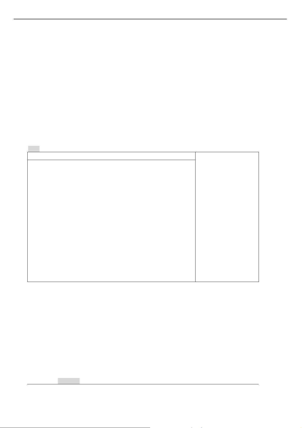
1. Overview
Intel Centrino platform notebook with Intel Dothan CPU up to 2.13GHz, 2.5 inch HDD,
Multimedia, LAN, Modem, IEEE1394, USB2.0,CARD Reader and PCMCIA. The fellow is a
summary of major components:
Main Chip:
CPU 0.09u Dothan Processor 1.73GHz-2.13GHz CPU with 2MB L2 Cache / 0.09u Celeron M 1.3GHz~1.6GHzwith
1MB L2 Cache(478P M-FCPGA)
CPU Core Power Semtech SC451
System 3V/5V Power Semtech SC1404
Core Logic: Intel 915GM + ICH6-M Chipset
Memory SO-DIMM 200pin DDR333 128MB/256MB/512MB/1GB DDR DRAM support
Clock Generator ICS954127
Graphic Engine Intel 915GM Build-in
Card Bus O2 OZ601 Single Slot, 32bit Cardbus Controller
Card Reader GL817E
Sound Codec :Realtek ALC655 (AC'97 Audio Codec Component Specification Rev.2.1).
Audio Amp.: TI TPA6011A4 for L/R Channel Audio (1Watt x 2)
IEEE1394 Ti TSB43AB22A(OHCI-1.1)
Keyboard Controller ITE 8510EX
LAN MAC + PHY: RealTek RTL8100CL Single Chip Solution
HDD Marvell 88SA8040 SATA to PATA interface
BIOS 4Mbit
Storage Devices:
CD/DVD ROM CD-RW/DVD Combo and Dual DVD (Options)
2.5"x9.5mm High Hard Disk Drive
ATA 100 Spec Support
USB External USB Storage device.
Legacy Support
Multimedia:
Sound
Two Build-in Dynamic Loud Speaker
1.5 watt x 4 ohm x 2 (Speaker) (4:3)
Two Audio Jacks Support ( Line Out x1, Microphone In x1)
Volume Control by Function key
Line Out Jack support
3
Page 4
TECHNICAL SERVICE MANUAL Prestigio Visconte 130
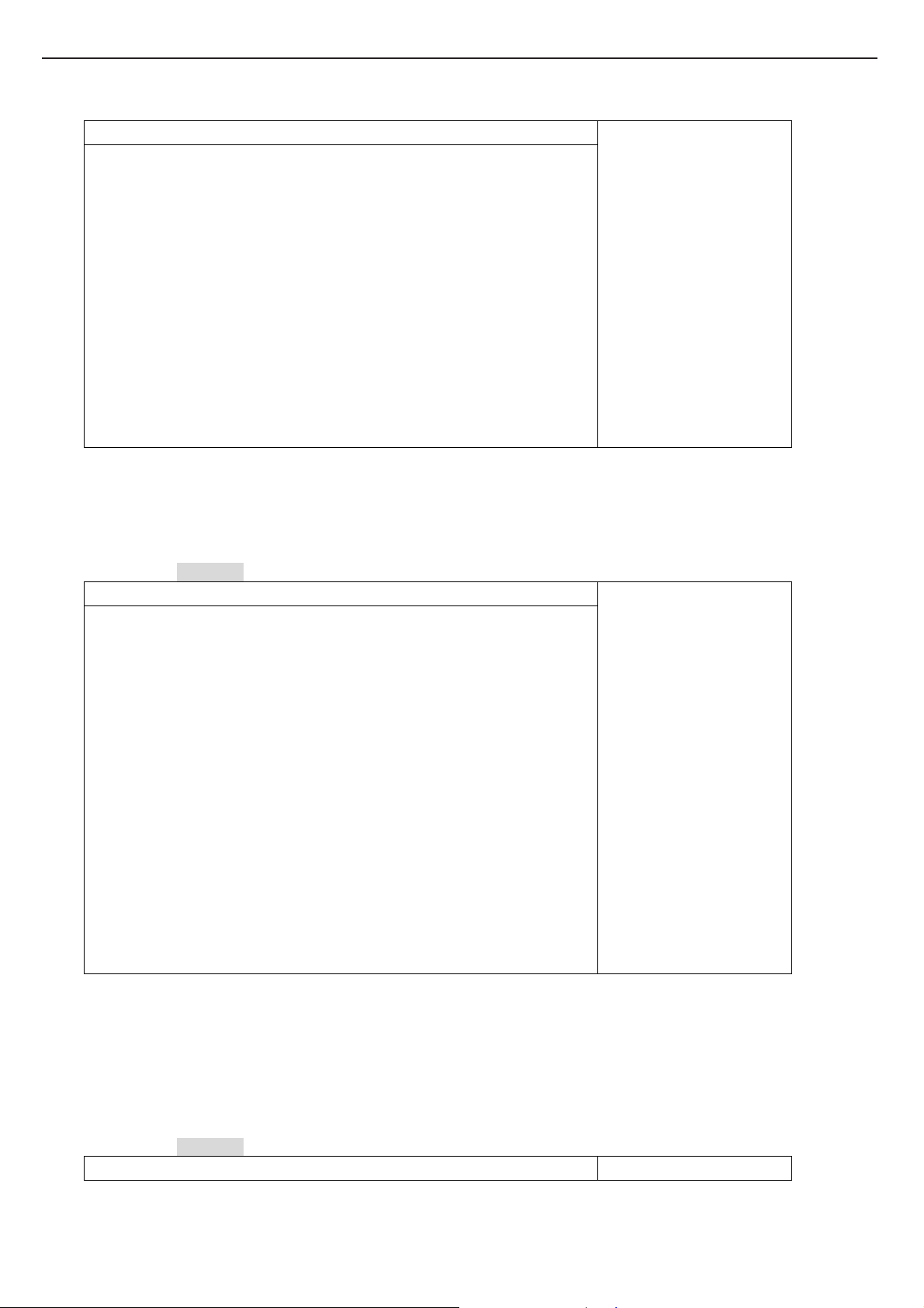
Communication / IO port:
RJ11 Standard AC97 MDC interface with Scatter, Gather and Burst capability
Wake on Ring on APM or ACPI mode through AC97 link
RJ45
USB2.0 Three USB2.0 connectors support.
IEEE1394 One IEEE 1394 Connector support
PCMCIA One Type II PCMCIA Slot
Card Reader One 3 in 1 memory card Slot, supports MMC / SD / MS memory card
CRT Standard 15Pin D-Sub Type CRT Connector
TV-OUT S-Video Connector support
Power:
AC Adapter
Battery module
LAN On board
65W (19V)
Smart battery with Dummy Charger architecture
Battery : 3S2P/3S3P with 2200 mAH Li-ion Cell Battery
Compliance:
PCI 2.2
PC99 compliant
ACPI compliant
4
Page 5

TECHNICAL SERVICE MANUALPrestigio Visconte 130
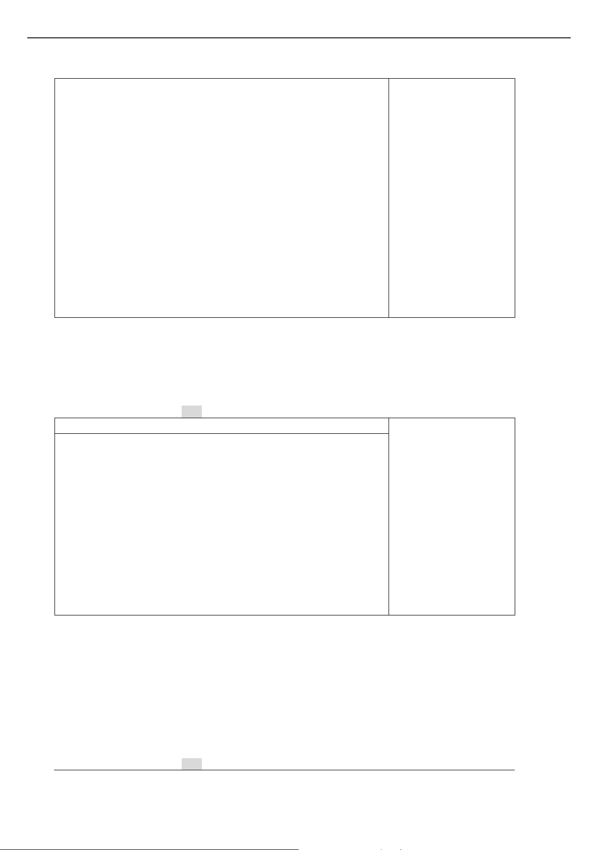
1.2 Functions Specification
1.2.1 Device Specification
Category Specification Note
CPU
Core Logic
Vendor: INTEL
Dothan (.09u) Celeron M (.09u) Processor 478pin 478P M-FCPGA Package
• Processor core/bus speeds: 1.73GHz-2..13GHz.
• On die L2 cache –1M/2M Bytes
• Fully compatible with previous Intel microprocessors
− Support for MMX technology
− Support for Streaming SIMD Extensions 2 (SSE2)
• Power Management Features Intel Enhanced Intel SpeedStep technology
• FSB: Dothan 533MHz/ Celeron M 400MHz
Vendor: INTEL
North Bridge: 915GM, South Bridge: ICH6-M
• Direct Media Interface (DMI)
- Chip-to-chip interface between GMCH and ICH6-M
- 2 GB/s point-to-point DMI to ICH6-M(1 GB/s each direction)
- 100 MHz reference clock (shared with PCI Express Graphics Attach)
• PCI to Host Bridge
− Support Intel Processor FSB at 533MHz
− AGTL+ Bus Driver Technology
• DRAM Controller
− Support 4 bank of 2.6V DDR SDRAM
− DDR 333 support (64-bit without ECC)
• PCI I/F (PCI 2.2 Compliant)
• System Interrupts
- Supports both 8259 and Pentium M processor FSB interrupt delivery mechanisms
• Integrated Graphic Support
• No External AGP Bus Support
• Integrate IDE controller
− HDD support “Ultra DMA/33, 66, 100
− CDROM support “Ultra DMA/33
• System Peripheral Support
− DMA Controller:
Two 8237A controller
8/16 bit DMA data transfer
Distributed DMA Support
− Interrupt Controller:
Two 8259A Compatible interrupt controllers
Level or edge triggered programmable
Serial Interrupt
− System Timer based on 8254 compatible programmable 16bit counters
− Real Time Clock with 256 Bytes Battery-backed RAM
− LPC-bus support for keyboard controller and super I/O
• USB controller 8 Ports
• AC'97 Audio and modem CODEC Interface Support
• SMBus controller
5
Page 6

TECHNICAL SERVICE MANUAL Prestigio Visconte 130
• System Power Management
• Integrated 10/100MB LAN MAC
System Memory Two Slot Standard 200-pin DDR SO-DIMM support
• Size: 128/256/512/1024 MB
• Type: DDR S DRAM 2.6V
• Frequency: PC2700 ( DDR333 )
• CL=2/2.5
• Operating ambient temperature: 0
• SPD Function Support
o
C ~ 70oC
IEEE1394
Clock Generator ICS954127
BIOS ROM 4Mb Flash EEPROM
VGA Controller Integrated Graphics
USB2.0 ICH6-M built in
Card Bus TI PCI1410
Card Reader GL817E
Sound Realtek ALC655
• T1 TSB43AB22A (OHCI-1.1 support)
• Vendor: ICS
• Generate System clock for CPU, DDR, PCI, USB and 14.318MHz.
• Provide Spread Spectrum function
• Vendor: AMIC
• Including system and VGA BIOS
• Support shadow system BIOS
• Support shadow VGA BIOS
• Core Frequency of 200 MHz
• 3D Setup and Render Engine
• High Quality Texture Engine
• 3D Graphics Rasterization Enhancement s
• 2D Graphics
• Video Overlay
• Compliant with Universal Serial Bus Specification Revision 2.0
• Compliant with Enhanced Host Controller Interface Specification Revision 0.95
• Compliant with Universal Host Controller Interface Specification Revision 1.1
• PCI multi-function device consists of two UHCI Host Controllers for
full/low-speed signaling and one EHCI Host Controller core for high-speed signaling
• 4 downstream facing ports in the root hub with integrated physical layer
transceivers shared by UHCI and EHCI Host Controllers
• Supports PCI-Bus Power Management Interface Specification release 1.1
• Legacy support for all downstream facing ports
• Vendor: TI
• PCI master device
• PC/Card Bus Type II X1 (Don’t support Type III device)
• Supports 3.3V/ 5V PC Card 16 cards and 3.3V Cardbus Card
• Vendor: Genesys Logic
• Supports MMC / SD / MS memory card
• Vendor: Realtek
• AC-97 codec
• Wavetable synthesizer support
• Integrate AC’ 97 Audio Codec 18bits (AC’97 2.1 compliance)
• Sound Blaster compatibility.
• Operating ambient temperature: 0
Audio Amplifier : TP A6011A
o
C ~ 85oC
6
Page 7
• Vendor: TI
• Provide Bridge-Tied Load or Single Ended Modes
KB Controller ITE 8510EX
• Vendor: ITE
• Internal KB controller
• Support PS/2 devices( Touch Pad)
• Support GPIO functions
• Two SMBus controller
• CPU temperature senser
• DAC support ( battery charge control )
• ADC support ( Inverter brightness control )
• X-BUS support ( BIOS )
• FAN speed control
LAN REALTEK RTL8100CL built-in Mac & PHY
• Plug & Play compatible
• 32bit PCI BUS master with DMA controller for low CPU and BUS utilization
• IEEE802.3 & 802.3u standard compatible
• Single 25MHz clock for 10 & 100 Mbps operation
TECHNICAL SERVICE MANUALPrestigio Visconte 130
7
Page 8
TECHNICAL SERVICE MANUAL Prestigio Visconte 130
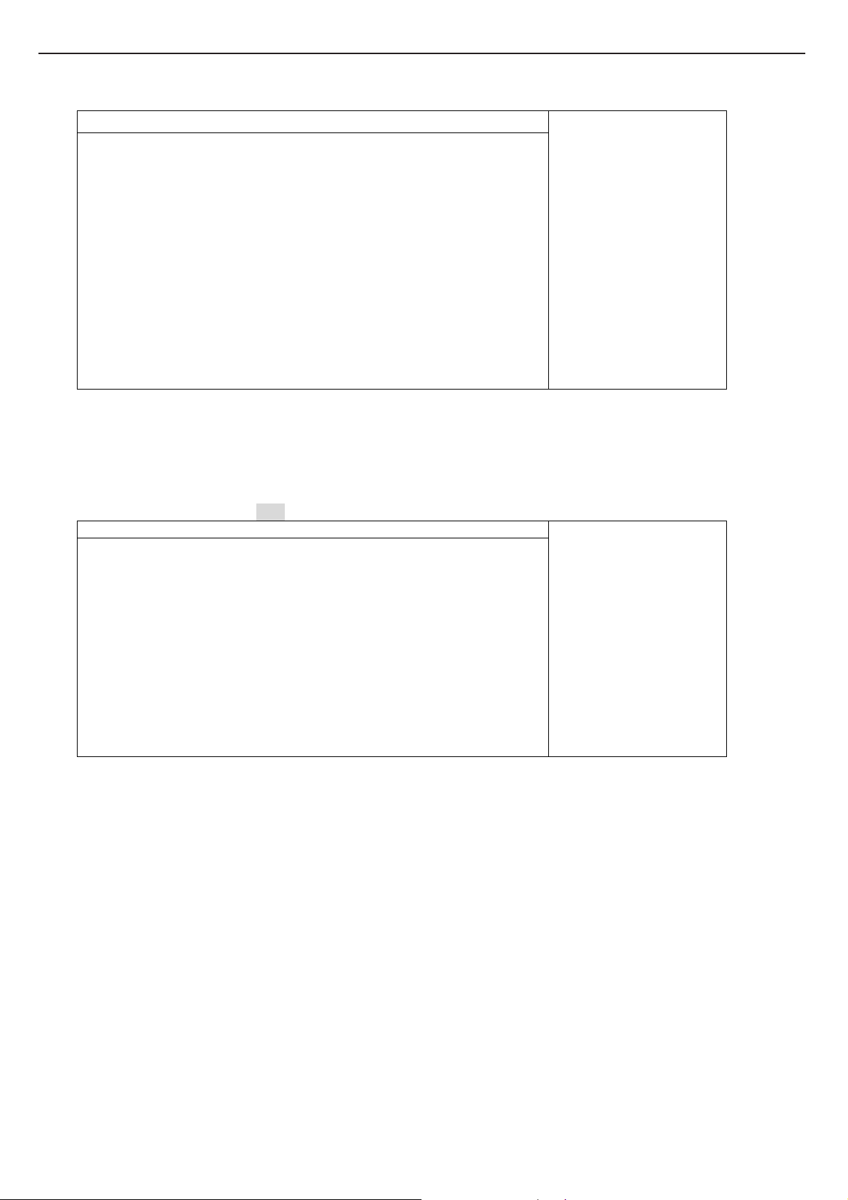
1.2.2 I/O Port
Category Specification Note
CRT Port
IEEE1394
USB
Line Out
Mic In
Modem
LAN
Card Bus Slot
Card Reader Slot
Point Device
INT/KB
Mini-PCI
TV-Out
1 Port (Standard D-Sub 9 Pin connector)
1 Port (OHCI-1.1 support)
3 Port: Base connector, 1.1/2.0 Compliant
1 Jacks (Stereo Mini Pin Jack)
1 Jack (Mono Mini Pin Jack)
1 Port (RJ-11)
1 Port (RJ-45)
Type II X 1 Supports 3.3V/ 5V PC Card 16 cards and 3.3V Cardbus Card
1 Port supports MMC / SD / MS / MS-Pro memory card
Internal Touch Pad – PS/2 mouse I/F
• Vendor: Synaptics
• Model:
• 2 buttons support Right/Left
Sumrex/ Chicony
•
Wireless LAN
• Optional
1 Port TV-Out ( S-Video)
8
Page 9
1.2.3 Power Supply
Battery
AC Adapter
RTC Battery
Converter
Battery Pack general spec.
• Gas Gauge: BQ2060
• Operating ambient temperature: 0
• Charge temperature: 0
• Self discharge rate: Fully charged battery will be at least 80% of full charge
• Protection: Over charge protection
• Pack Vendor: SMP/Foxlink/GLW
• Capacity: 2200mAH Li-ion battery
• Cell Vendor: 3S2P-> 3.7V Samsung/LG, 3.6V Panasonic
• Size: 18650
• Pack Configure: 3S2P / 3S3P
• Pack Capacity: 3S2P-> 4400mAH, 10.8/11.1V, 43.2/48.8W
Charge Strategy
Dummy Charger Battery architecture
• Charger: ITE8510EX
• Charge Current: System off Max. 2.0A.
• Charging terminate: Charging current lower than 200mA
Battery voltage up to 16.8V.(SMBUS)
Battery temperature over 50 degree C (SMBUS)
Charging time over 6 hrs
Vendor :Li-Shin, Liteon, Hipro
Input: AC 100~ 240V, 50/60Hz
Output: 19V, 3.42A, 65W
Real-time clock/calendar with a coin type battery back up.
Vendor: KTS BBBCR2032B
Voltage: 3V
Capacity: 220mAh
RTC Power Plane Power Consumption: 5uA / 3V
Estimated RTC Battery Life: 2 years
Output Tolerance Max load Test spec
5.0V +/- 5% 4.5A 5.5A
3.3V +/- 5% 4.5A 5.5A
12V +/- 5% 0.2A 0.2A
2.6V +/- 5% 4.5A 5.0A
1.8V +/- 3% 1.5A 2.0A
1.5V +/- 3% 4.0A 5.0A
1.05V +/- 3% 4.0A 5.0A
o
o
C ~ 60oC
when stored at 25
Over and under voltage protection
Over current protection
Thermal protection
3S3P-> 3.7V Samsung/LG, 3.6V Panasonic
3S3P-> 6600mAH, 10.8/11.1V, 43.2/48.8W
System on Max. 0.7A
C ~ 60oC
o
C, 85% RH for a period of one month
TECHNICAL SERVICE MANUALPrestigio Visconte 130
DC/DC
9
Page 10
TECHNICAL SERVICE MANUAL Prestigio Visconte 130
1.2.4 Power-On Source
No Note
System Power Button *System power on control
1.
*Push this button 4 sec will happen H/W power shut down
This item works both when system is at on and off state
Besides RTC and AUX power plane, all power plane will turn
off until the releasing of the power button
1.2.5 Power Plane
Name Level System off System on Standby STD W/O AC & BAT
No
VCC3_AUX 3.3V
1.
VCC5_AUX 5V
2.
12V_AUX 12V
3.
VCC3_SUS 3.3V OFF
4.
VCC3 3.3V OFF
5.
VCC5 5V OFF
6.
VCC2.6 2.6V
7.
VCC1.8 1.8V
8.
VCC1.5 1.5V
9.
VCC1.05 1.05V
10.
12V 12V OFF
11.
RTCVCC 2.0~3.3V
12.
VCCP 1.05V
13.
VCC_CORE 1.484V
14.
ON ON ON ON OFF
ON ON ON ON OFF
ON ON ON ON OFF
ON ON OFF OFF
ON ON OFF OFF
ON ON OFF OFF
OFF ON ON OFF OFF
OFF ON ON OFF OFF
OFF ON ON OFF OFF
OFF ON ON OFF OFF
ON ON OFF OFF
ON ON ON ON ON
OFF ON OFF OFF OFF
OFF ON OFF OFF OFF
1.2.6 Connector
Connector Location Pin No
No
1. DC_IN CON CON1 6
2. SW Board FFC CON CON2 32
3. INT K/B CON CON3 24
4. TOUCHPAD FFC CON CON5 6
5 AUDIO FFC CON CON6 40
6 Battery CON CON9 10
7 CPU FAN CON CON10 3
8. DVD-ROM CON CON11 50
9. LCD CON CON12 30
10. INVERTER CON CON13 10
11. LAN Wire CON CON14 10
12. IO Wire CON CON16 18
13. MODEM BOARD FFC CON CON17 8
14 INT MIC CON (Option) CON18 2
15. PADA HDD CON CON19 44
16. BLUETOOTH WIRE CON (Option) CON20 5
17 MINI PCI CON CON21 124
18. DDR SO-DIMM CON30 200
19. DDR SO-DIMM CON31 200
20. SATA HDD CON (Option) CON32 22
21. CARD BUS FFC CON CON100 32
22. CARD BUS FFC CON CON101 32
23. SUB BAT CON CON102 2
10
Page 11

TECHNICAL SERVICE MANUALPrestigio Visconte 130
24. DC_IN JACK SCN1 5 In Switch Board
25 DC_IN CON SCN2 6 In Switch Board
26. SWITCH BOARD FFC CON SCN3 32 In Switch Board
27 CRT CON SCN4 15 In Switch Board
28 TP/MB FFC CON TCN1 6 In TouchPad Board
29 TP FFC CON TCN2 12 In TouchPad Board
30 LED CON LCN1 14 In LED Board
31 MODEM WIRE CON MCN1 2 In Modem Board
32 MODEB FFC CON MCN2 8 In Modem Board
33 USB CON MCN5 4 In Modem Board
34 RJ11 JACK MCN10 2 In Modem Board
35 LINE OUT JACK CN2 6 In Audio Board
36 MIC JACK CN3 6 In Audio Board
37 Cardreader CON CN4 26 In Audio Board
38 MDC CON CN7 12 In Audio Board
39 USB CON CN8 4 In Audio Board
40 LED CON CN9 14 In Audio Board
41 AUDIO FFC CON CN10 40 In Audio Board
42 SPEAKER CON CN11 4 In Audio Board
43 S-VIDEO ICN1 4 In IO Board
44 LAN JACK ICN3 8 In IO Board
45 IO WIRE CON ICN4 18 In IO Board
46 LAN WIRE CON ICN5 10 In IO Board
47 1394 CON ICN6 4 In IO Board
48 USB CON ICN10 4 In IO Board
49 PCMCIA SOCKET PCN3 68 In PCMCIA Board
50 CARD BUS FFC CON PCN100 32 In PCMCIA Board
51 CARD BUS FFC CON PCN101 32 In PCMCIA Board
1.2.7 Cable
Cable
No
1. DC_IN cable M/B to Switch BOARD
2. SWITCH Board FFC M/B to Switch BOARD
3. IO cable M/B to IO BOARD
4. Lan cable M/B to IO BOARD
5 LCD cable M/B to LCD
6 INV cable M/B to Invertor
7 MODEM FFC M/B to Modem BOARD
8 TOUCHPAD FFC M/B to TOUCHPAD BOARD
9 CARD BUS FFC x 2 M/B to PCMCIA BOARD
10 AUDIO Board FFC M/B to AUDIO BOARD
11 MDC cable MDC to Modem BOARD
11
Page 12

TECHNICAL SERVICE MANUAL Prestigio Visconte 130
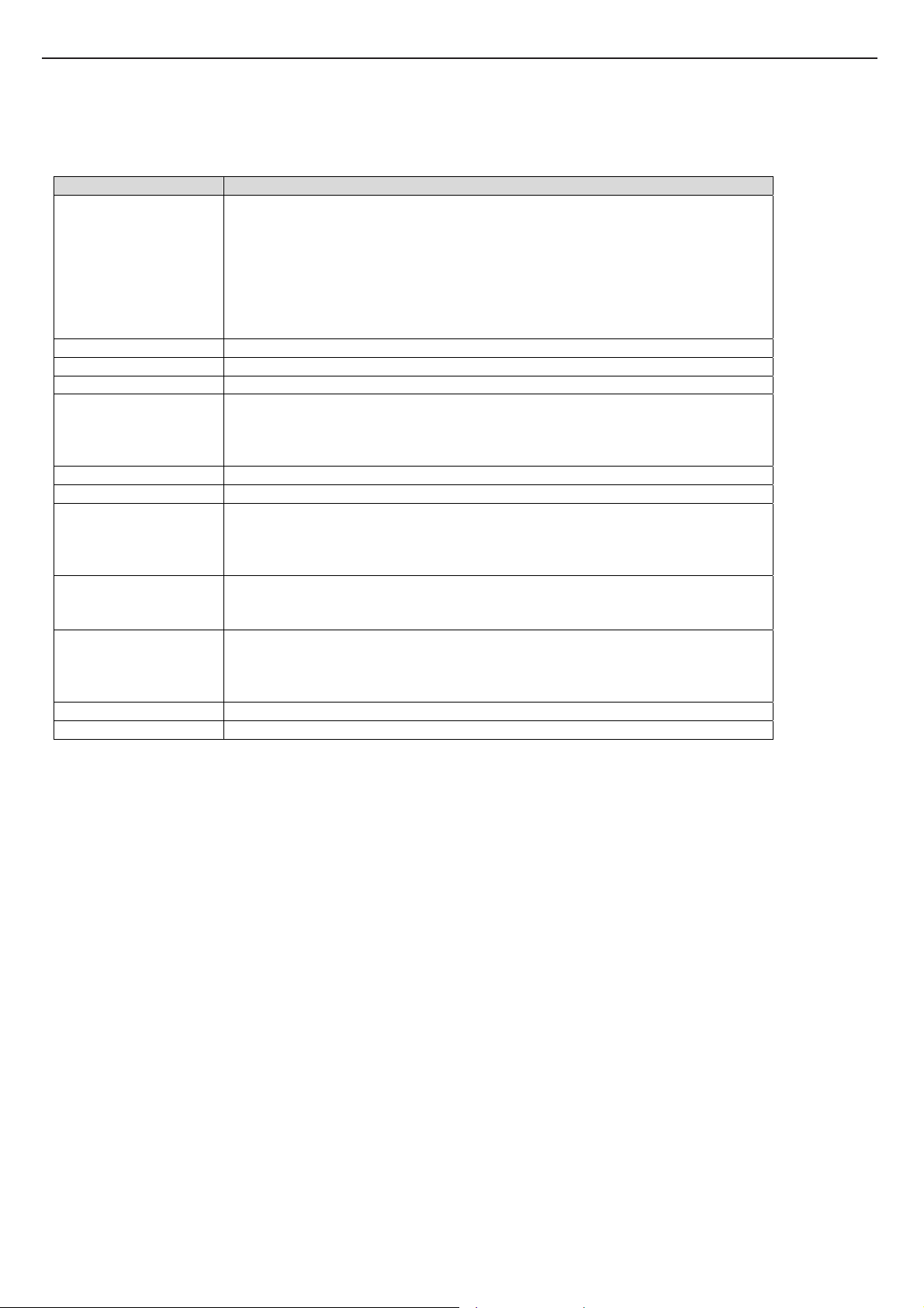
1.2.8 LED
POWER ON/OFF Blue light always on when system is in Power On.
POWER/Charging Status Orange light flash shown when battery is being charge d
Green light is shown when battery is not charging and Battery capacity is Full.
Red light flash when battery is low warning
RF_ON Blue light always on when WIRELESS Card RF activated
SUSPEND Status Green light flash when system is during suspend
Green light always on when system is in silent mode
HDD/ODD LED ON when HDD/ODD activated
Num lock LED O N wh en activated. Num Lock OFF at default
Caps lock LED ON when activated. Caps Lock should be OFF at boot up
12
Page 13
2. Software Specifications
2.1 Product Specification
Process
or
Memory DDR
Core
Logic
VGA Integrated
KBC/EB
C
PCMCIA
card
IEEE
1394a
S-Video Intel 915GM
LAN
Controll
er
Modem
Wireless
LAN
Keyboar
d
Pointing
Device
LCD 13” TMD
HDD Hitachi/WD
Optical
Device
Card
reader
Synaptics TM15P-UZ378
Intel
Intel 915GM
(Alviso)
+ ICH6-M
IT8510EX
OZ601
TSB43AB22A
Integrate
RTL8100CL
Intel 2200BG
MSI 6833A &
LTD133EX2A
Lite-On/QSI/HLDS
GL817E
▓TDP 27W
▓Dothan CPU
Pentium M, Operat ing to 2.13 GHz, 533 MHz FSB, 2MB L2 cache
Celeron M, Operating to 1.60 GHz, 400 MHz FSB, 1MB L2 cache
▓DDR1 333
▓DDR RAM socket * 2
▓System RAM up to 1GB total
**1GB memory is depends on module’s availability and customer’s
request.
▓Host Interface:
Supports a FSB frequency of 400 and 533 MHz of Dothan series CPUs
▓System Memory Interface:
Supports DDR1 memory interface
Supports DDR1 333 SO-DIMM module
▓DMI Interface:
Chip-to-chip interface between GMCH and ICH6-M
▓Supports DX9
▓ACPI 2.0b compliant
▓16-bit RISC core, with 2 Mbytes address space, and running at up to
20MHz
▓PCMCIA card support
▓Support IEEE 1394a with Open HCI Compliance
▓PCI V2.2 MAC/BIU supports
▓Display on a PAL or NTSC TV
▓Support for Macrovision 7.1 copy protection standard-a fully
programmable timing capability
▓Supports 10 and 100 Mb/Sec
▓Standard AC97 MDC interface with Scatter, Gather and Burst apability
▓Wake on Ring on ACPI mode through AC97 link
▓Supports ITU v.92/v.90
▓Mini-PCI interface
▓IEEE802.11b/g standard compliant
▓86Keys K/B
▓PS/2 Touch P ad with 2 buttons and page down/ page up
▓13.3 " WXGA (16:9) resolution 1280 x 800
▓2.5" 9.5mm IDE HDD with PATA support
▓Combo, DVD Dual
▓GBAS support
▓Support 3 in 1 card reader SD/MMC/MS memory card
▓USB 2.0 compliant
▓Support boot function
TECHNICAL SERVICE MANUALPrestigio Visconte 130
13
Page 14
TECHNICAL SERVICE MANUAL Prestigio Visconte 130
Battery
Pack
AC-Adap
ter
I/O Port
System
Status
Indicato
r
Quick
Launch
Button
Power
Cinema
under
Linux
Speaker
Power
Button
O.S.
BIOS
Power
Manage
ment
Physical
Outline
EMI
RF
Telecom
Safety
Accesso
ry
(Option
al)
Samsung
Lite-On
(2-pin)
▓ 1 x DC-in jack (2-pin)
▓ 1 x S-Video output port (4-pin)
▓ 1 x IEEE 1394a port
▓ 2 x Phone jacks for microphone input / audio output:
a). External microphone jack 1/8”
b). External earphone jack 1/8”
▓ 1 x RJ45 LAN
▓ 1 x RJ11 modem connector
▓ 1 x PCMCIA
▓ 3 x USB 2.0 ports
▓ 1 x CRT port
▓ 1 x MMC/MS/SD memory card slot
▓Num Lock: Green
▓Caps Lock: Green
▓ODD, HDD R/W: Green
▓RF-ON (Wireless LAN): Blue
▓Power On, Suspend: Blue / Blue flash
▓Battery status Charging/ Low: Green/ Orange / Orange flash
▓Power Cinema/ Silent Mode: Green
▓Multiple function button for PCM On/Off and Silent mode
▓WLAN On/Off button
▓On / Off
▓Support DVD player, MP3 player, CD player, USB storage devices reader, View photo
▓Build-in 2 speakers
▓Speaker : 1.5W and 4 ohm
▓On/ Off: Programmable Power Buttons
▓1 Sec. -> Suspend, 4 Sec. -> Power Off
▓Post 1 Sec. to power off
▓Supports Windows XP
▓Supports PnP, APM 1.2 & ACPI 2.0
▓Support external USB flash memory card boot up.
Uniwill “Smart Power II” Power Management (TBD)
▓Proprietary Technology of battery life and system performance Extension
The technology is including Long battery life mode, Silent mode
Long battery life mode: Battery life extension
Silent mode: Noise frequency under 25dB and Maximum battery life
▓Dimension: LxWxH: 316mmX224mmX31.9~34.4(w/battery) (TBD)
▓Weight: 4.5lb (TBD)
▓FCC, VCCI, CE
▓FCC, R&TTE, CSA
▓CTR21, CSA
▓UL, cUL, CB, TUV, JATE, BSMI
Port replicator
Uniwill PR8800
▓Li-ion Smart Battery with BQ-2060 Gas Gauge IC
▓6 cells, 11.1V/4400mA (3S2P), 3.7V/ 2200mAH/ Cell, Samsung
▓Battery life (TBD)
▓50/60Hz 65Watts 19V
▓CRT upstr eam port
▓VGA display swappable support
14
Page 15

TECHNICAL SERVICE MANUALPrestigio Visconte 130
*** The content is subjected to change without notice.
Function Key define :
F1 TBD(Nothing to do)
F2 into COMS
Fn + F3 Screen on/off(backlight on/off)
Fn + F4 Hibernation
Fn + F5 Switch to CRT
Fn + F6 Brightness down
Fn + F7 Brightness up
Fn + F8 Volume down
Fn + F9 Volume up
Fn + F10 Silent(it mean "if end users press Fn+F10 = mute on" , press Fn+F10 again = mute
off.)
2.2 Preface
The software engineering specification is a deployment from product marketing specification. It should outline majo r
tasks to be implemented in a specific model. For any model which has been defined from product marketing division, there
should have a product marketing specification comes out.
The purpose of this specification i s to be a n impl ementati on guideline for engi neers who a re respon sible for t he model. It
intends to avoid ambiguity about function definitions so as to allow engineers to shorten their implementation period.
The specification covers all the bundled software components which including BIOS, Micro-Controller, device drivers
and applications. The target Operating Systems will be Windows XP. The device drivers and applications are options based on
per-customer’s requirements. The engineers should make sure that these drivers and application could run without any
difficulties on the target PC2001 model.
The readers of this specification are assumed to have enough experiences and knowledge to understand whatever in the
context. The specification will not intend to explain any detail of specific topic.
15
Page 16
TECHNICAL SERVICE MANUAL Prestigio Visconte 130
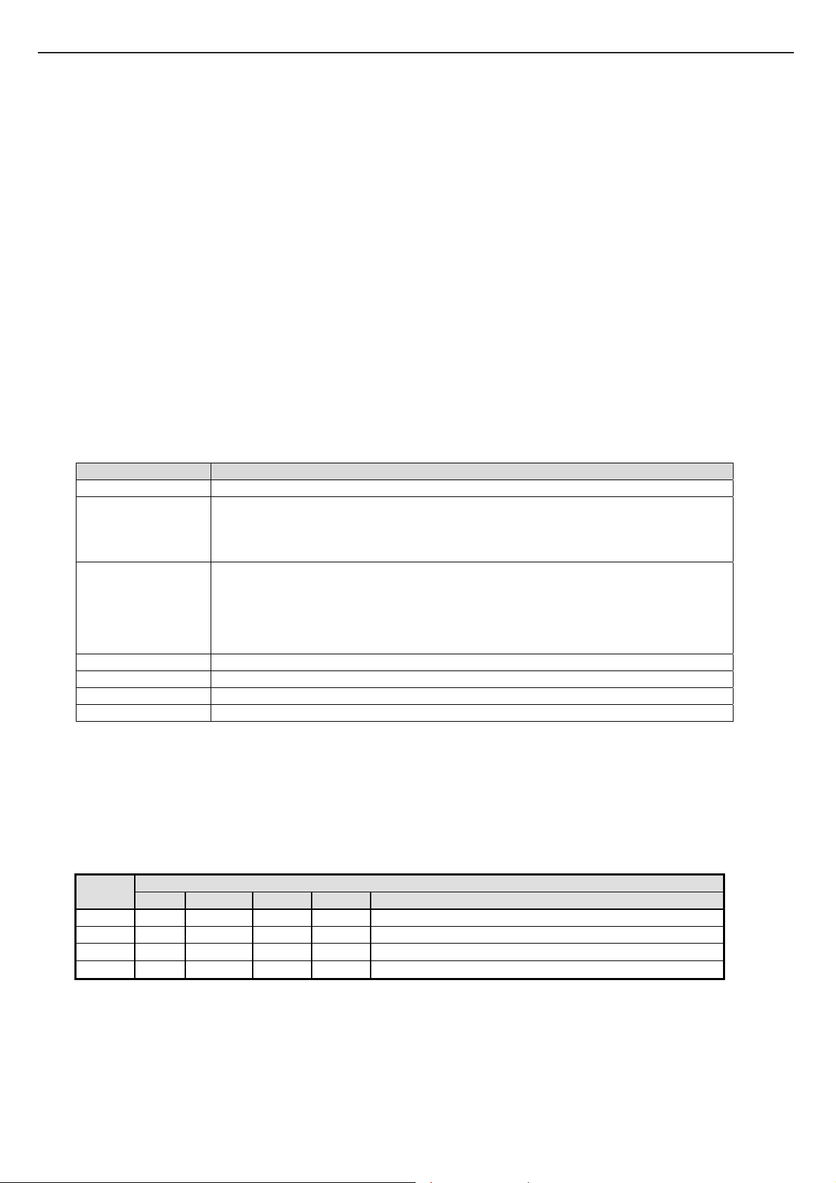
2.3 Summary of BIOS Specification
Feature Description
Basic Bios Features POST(Power On Self Test)
Quiet Boot (optional show OEM Boot Logo)
Multi-Boot
APM 1.2 Compliance
Support ACPI 1.0b Spec.
Support PCI 2.1 Spec.
Support WindowsXP
Support SMBIOS 2.3 Spec.
CPU Auto detect the CPU type and speed
DRAM Auto detection and sizing up to 1GB
Cache Auto detection and sizing, and always enabled
Hard Disk Support PAT A IDE detection
Support LBA mode for large capacity HDD > 8GB
Support Ultra DMA 33/66/100
Support Fast PIO mode 4
Multi-Boot Support boot from HDD, CDROM/DVD-ROM, LAN, USB removable devices
Crisis Disk Support Flash BIOS from BIOS Boot Block
Plug and Play Support PnP runtime service and Conflict-Detection-Resolve during POST
Support SMBIOS2.3
Auto routing PnP device I/O, Memory, IRQ and DMA
Support ACPI 2.0 Device Management
Keyboard Controller WHQL Keyboard Logo compliance
Support hot plug/swap external PS/2 mouse and keyboard
Support Fn hot-key
Power Management Support ACPI 1.0b power management
Support system S3, S4 state
Support CPU C0, C1 ,C2, C3state
Support Uniwill Smart Power control by EC
Instant On Support Instant On button to boot to Linux with DVD/MP3/Photo Player function
Core Logic INTEL915GM + ICH6M
2.4 SYSTEM
2.4.1 System Memory
The System consist s of DDRI mem ory on 64-bit bus and the size opti ons are 128/256/51 2MB on each DIMM slot. The
BIOS will automatically detect the amount of memory during POST.
2.4.2 VGA
The VGA chip is Intel 915GM Build in VGA
There’re some limitations like below:
1. Display not allow switching while playing DVD/VCD
2. TV display cannot full fill screen at XP dosprompt full screen mode
2.4.3 Audio
The audio controller i s integra ted in south bridge and th rough the AC97 data line to external CODEC to reduce the noise
16
Page 17
TECHNICAL SERVICE MANUALPrestigio Visconte 130
caused by PCB’s layout. According to the H/W architecture , the BIOS will recognize it as a PCI device and initialize it in PCI
bus initialization. The PCI legacy audio mode is not to be supported.
2.4.4 Modem
The system can use all of the modem that is AC97’ compliance and the MDC form factor. During POST, the BIOS will
detect the existence the MDC and set proper registers in south bridge
2.4.5 PCMCIA
The OZ 601T supports a variety of features . PCcard , CardBus
2.4.6 Card Reader
Card Reader via USB bus, support SD Card , MMC, Memory Stick, Memory Stick Pro
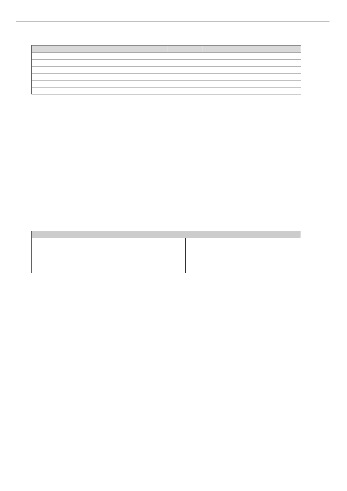
2.4.7 LED Indicator
Indicator Functi on Description
Power/Suspend LED The LED will turn blink gr een when system is suspend
Charge LED The LED will always off when without Battery
The LED will turn on green when Battery Full Charged
The LED will turn on orange when Battery Charging
The LED will turn on red when Battery Low warning
Wireless LED
Silent LED The LED will turn on when system entry silent mode
Num Lock LED The LED will turn on when Num Lock function is activated
Cap Lock LED The LED will turn on when Cap Lock function is activated
HDD/CDROM LED The LED will turn on when the hard disk or CDROM is activated or accessed
1. Setup menu can define RF enable or disable
2. Load default = RF enable , The LED will turn on blue
3. Without WALN card = always disable
4. Into suspend = RF disable
5. Before Power off & Suspend need keep RF status for setting next power on & resume .
Power on the system will turn on Cap, ,Num lock LED about 1~2 seconds then turn off them.
.
2.4.8 PCI Device
All the PCI devices will occupy the system resources, such as I/O, Memory and IRQ, especially the IRQ assignment is
relative to H/W and system arrangement. The following will list all PCI devices:
PCI Device IDSEL
Bus# Device# Func# INT Pin Device Name
PAD20 1 3 0 B OZ601 PCMCIA
PAD26 1 10 0 A TI TSB43AB22A IEEE-1394
PAD28 1 12 0 A LAN RTL8100CL
PAD19 1 7 0 A, B MINI PCI DEVICES
2.4.9 SMBus Devices
The SMBus is a two-wire interface through which the system can communicate with power-related chips. The BIOS
should initialize the SMBus devices during POST.
17
Page 18
TECHNICAL SERVICE MANUAL Prestigio Visconte 130
SMBus Device Host/Slave Address
ADM1032 (Temperature) Slave 4Ch
Battery Slave 16h
ICS954127 (Clock Generater) Slave D2h
SO-DIMM SPD Slave A0h, A2h
AT24C02 (IEEE-1394 EEPROM) Slave
93C46 (LAN EEPROM) Slave
2.4.10 GPIO Pin Assignment
The following will list the core chip GPIO definition and function:
General Purpose Inputs
Pin Name Function Name Type Signal Description
GPI8 RUN_SCI# Input 10Kohm pull high
GPIO31 LCDSEL0# Input Select LCD type
GPIO30 LCDSEL2# Input Select LCD type
GPIO29 LCDSEL1# Input Select LCD type
2.5 Keyboard Controller
The system uses the ITE IT8510E as the keyboard controller and ACPI embedded controller. Following will summarize all
the features of keyboard firmware.
z Uniwill Smart Power support
z Internal Keyboard and Auxiliary Device Support and Internal Pointing Device Support.
z Internal Keyboard Scan Code Controller Support and Internal Numeric Keypad Support.
z Simultaneous Operation of External Devices
z Simultaneous Operation of External Keyboards
z Simultaneous Operation of External Auxiliary
z Device Hot Pluggability
z Embedded Controller IT8510E 176 -Pin LQFP package
z LPC System Interface
z ACPI Embedded Controller Power Management Event Control.
18
Page 19

z Single Pin Keys Support .
z PS/2 Interface External Port Support support.
z System Power On/Off ATX Power Sequence Control.
z System BIOS Strap Pin.
z System BIOS ROM Flash Protect.
z FAN DAC or speed Control.
z LCD Backlight Brightness Adjust.
z Direct LEDs Support.
TECHNICAL SERVICE MANUALPrestigio Visconte 130
2.5 Power Management
INPUT :
Input voltage range : 9V~17Vdc (Battery) or 18V~21.5Vdc (Adaptor).
Adapter: 20V @ 3.25A,65W constant voltage mode .
Battery: Main Battery: 4 Cells (4S1P) DC 14.8V 2200mA
3 Cells(3S2P) DC 11.1V 2200mA/2000mA
Second Battery: 3 Cells(3S1P) DC 11.1V(Option) 2200mA
2.5.1 General Requirement
The purpose of the Power Management (PM) is trying to reduce the power consumption of the system and extent the
battery life, increase the time without recharging the battery. The Advanced Configuration and Power Interface (ACPI)
specification is the latest and better PM method and will replace the traditional APM and PNP functions. ACPI is a kind of
Operating System Directed Power Management (OSPM), that is, the OS will control the system/devices to enter proper
power-saving mode and determine when to do it.
The BIOS shall provide the ACPI table that is written by ASL language, to tell the OS how to setup and control the
system/device configuration and the power-saving mode. So the system H/W, BIOS and drivers must be meet the ACPI
specification:
ACPI 1.0b compliant
Intel Geyserville III Technology Support
Supporting processor power state C0, C1 , C2 ,C3
Supporting system state S0, S3, S4 (WinXP) and S5
Support Un iwill S mart Power Function
First of all, the next section will depict the power management state transition, then describe the definition for each
19
Page 20
TECHNICAL SERVICE MANUAL Prestigio Visconte 130
system state.
2.6 Power Management State Transition
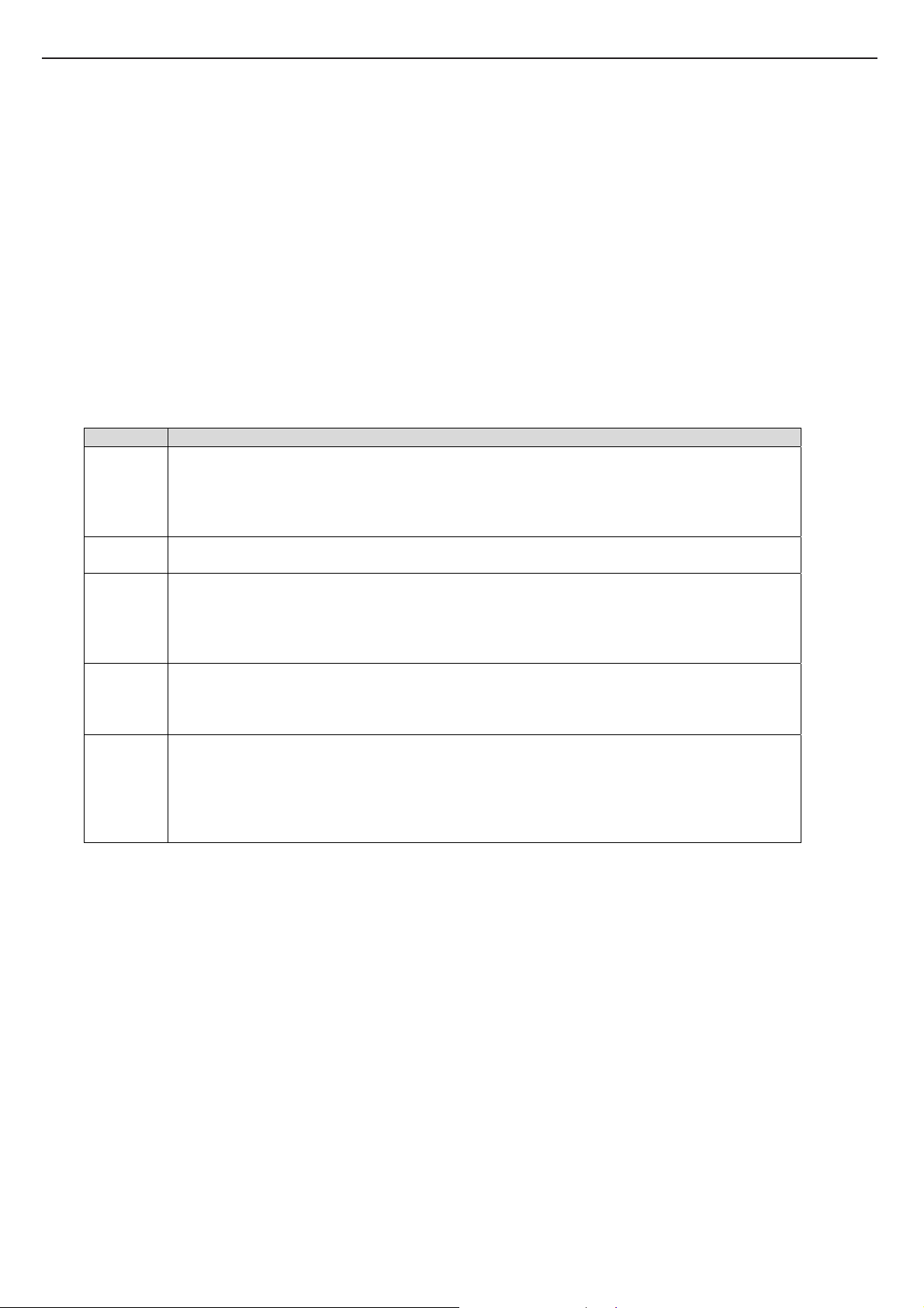
2.6.1 Power Management Mode Definitions
Each system (or model) may have different PM model and state definition. For clear, see the following table :
PM Mode Definitions
Full-On The CPU runs in full speed and all the devices are power on. The system can respond to all
applications with maximum performance.
1. The system is in the state S0.
2. The CPU is in the state C0.
3. All the devices are in the state D0.
Geyserville
III
Idle This mode is similar to Full-On . The CPU might change into C1 or C2 state depend on the OS, in
Suspend The state is more power saving than above, the CPU and most of parts power will be cut off except
SOFF/STD The state is the most power saving mode, all of the parts in the system will power off, except the
When system is in suspend mode (S3 state ), external keyboard/mouse/touch pad/Lid cannot be the wake up event source.
CPU will running between diffenent BUS ratio depend on system loading, if power Schemes set to
Presentation or Max Battery
order to save CPU power consumption.
1. The system is in the state S0.
2. The CPU is in the state C1 or C2.
3. All the devices are in the state D0.
DRAM system.
1. The system is in the state S3.
2. The CPU and all of devices are power off except DRAM system.
keyboard controller enter to idle mode continuously to control the battery charging and monitor power
button.
Note: Before enter to S4, the OS will save all of data or registers in HDD.
1. The system is in the state S5 or S4.
2. The CPU and all of devices are power off.
Only Power button can resume the system.
2.6.2 Uniwill Smart Power Function
The purpose of Smart Power is to save the power consumption during the system is not busy. This function not only save the
power of Battery to extend the Notebook’s battery working time, but also reduce the the temperature of CPU / Chip and keep
system working in a lower temperature to extend the CPU and whole system’s life. Reduce temperature will also keep
Operation System work stable.
2.6.2.1 Instant On Mode: If press Instant On button to power on, CPU FSB 400 ext. clock will keep at
80MHz, CPU FSB 533 ext. clock will keep at 90MHz CPU bus ratio will keep at the minimum.
2.6.2.2 Long Battery Life Mode: Also called Smart Power 1, CPU FSB 400 ext. clock will keep at
100MHz, CPU FSB 533 ext. clock will keep at 133MHz CPU maximum bus ratio will keep at the most
20
Page 21

TECHNICAL SERVICE MANUALPrestigio Visconte 130
lower level 4 when battery mode detected (ex. Banias 1.7G 6 point will keep maximum at level 2, Dothan
1.8G 7 point will keep maximum at level 3). This option can be enabled/disabled by CMOS setup.
2.6.2.3 Silent Mode: The FAN will stop or run at very low speed to keep system slient. In Windows XP
OS press Instant On button will toggle Silent mode. CPU FSB 400 ext. clock will decrease to 80MHz,
CPU FSB 533 ext. clock will decrease to 90MHz CPU bus ratio will keep at the minimun no matter AC
mode or Battery mode when Silent mode enabled.
2.6.3 CPU Fan Control
In the system use the fan as the active cooling device. It is not necessary always turn on full speed, so following will
depict the method and specification of fan speed control. Before it we would like to define the fan speed:
Please refer to SmartPower Management Software Designer’s Guide
Because fan will consume some power and make some noise, the system will try to keep the fan in low speed and keep the
system in high performance as possible. Unfortunately, there are some trade-off among some factors: thermal, noise and CPU
performance, so we increase the fan speed as active cooling method and triger the CPU clock throttling as passive cooling
method. The CPU clock and fan speed is controlled depend on the CPU temperature from hardwire thermal monitor.
2.6.4 The backlight control of LCD
The LCD panel is another key parts that will consume more power of the notebook system, so there is a way to reduce the
power consumption on battery only, e.i. reduce the brightness of backlight when end-user unplug the AC adaptor.
The backlight is controled through the KBC controller, and it is divide into 8 levels from darkest to brightest. The KBC
bios know the status of power source and the current backlight’s brightness any time. When the AC adaptor unplug, the KBC
will reduce the brightness one or two level automatically.
There is another approach to control the backlight, it will be turn off when LCD cover is close (LID switch), conversely,
it will be turn on when LCD cover is open
The Fn+F6/Fn+F7 adjusted the backlight. And BIOS keep it temporality. The next boot will go to the default
setting of backlight.
When internal keyboard and touchpad have not data input Embedded Controller about 10 minutes the LCD
Backlight will reduce. If embedded controller has input from keyboard or touchpad the backlight will recover.
21
Page 22

TECHNICAL SERVICE MANUAL Prestigio Visconte 130
2.7 Crisis Disk
Crisis Disk function can recover the BIOS back if flash BIOS fail and can’t boot up due to lost power while BIOS flashing or
any other situations. Operation as below:
2.7.1 Crisis Disk options: There’re 3 kinds of Crisis Disk options (Press Key Conbine) as below
2.7.1.1 Ctrl-Home: NVRAM data (DMI string) will be preserved, CMOS data will be destroyed after
flash.
2.7.1.2 Ctrl-PageDown: both NVRAM and CMOS data will be preserved.
2.7.1.3 Ctrl-PageUp: both NVRAM and CMOS data will be destroyed.
2.7.1.4 The correct way to press these combine key is, Press and Hold “Ctrl” key, then Press and
release the second key (ex. Home) several times.
2.7.2 Prepare a Floppy Disk contain BIOS ROM file
2.7.2.1Complete Format a Floppy Disk, to make sure there’s no bad sector
2.7.2.2 Rename the BIOS ROM filename to “AMIBOOT.ROM” and copy this file into the Floppy Disk
2.7.2.3Insert the Floppy Disk into USB Floppy Disk Drive
2.7.2.4Insert the USB Floppy Disk Drive into any USB port
2.7.3Start to flash BIOS with Crisis Disk Function
2.7.3.1 Insert AC adaptor, in case the Battery is too low to shutdown during flashing BIOS
2.7.3.2 Press Power Button to turn on power
2.7.3.2 Press “Crisis Disk option key” (ex. Ctrl-Home) several times
2.7.3.3 Watch the USB Floppy Disk Drive is accessing a while
2.7.3.4 Screen will show a “Starting FLASH Recovery.” message while flashing BIOS
22
Page 23
TECHNICAL SERVICE MANUALPrestigio Visconte 130
2.8 CMOS Setup Menu
The setup function only can be invo ked by pressing F2 key during POST that provide a appr oach to change some set ting and
configuration the user prefer, and the changed values will save in the battery backup RAM of CMOS RTC and will take effect
after the system rebooted. The setup uses a menu interface to allow the user to configure their system and the features are briefly
listed as follow
Press F12 key for Boot Menu
2.8.1 Main Menu
BIOS SETUP UTILITY
Main Advanced Boot Security Power Exit
System Overview
BIOS Information
BIOS Version : (OEM BIOS Version)
KBC Version : (OEM KBC Version)
Build Date : (BIOS build date)
Processor
Type : (detected Intel CPU type xxxx)
Speed : (detected CPU real Speed)
System Memory
Size : (detected memory size xxxMB)
System Tim e [00:00:00]
System Date [Tue 01/01/2003]
V02.57 (C)Copyright 1985-200 5, American Megatrends, Inc.
2.8.2 Advanced Menu
BIOS SETUP UTILITY
Main Advanced Boot Security Power Exit
Use [Enter], [Tab]
Or [SHIFT-TAB] to
Select a field..
Use [+] or [-] to
Configure system Time.
←→ Select Screen
↑↓ Select Item
+- Change Field
Tab Select Field
F1 General Help
F10 Save and Exit
ESC Exit
23
Page 24
TECHNICAL SERVICE MANUAL Prestigio Visconte 130
Advanced Settings
WARNING: Setting wrong values in below sections
May cause system to malfunction.
>Primary IDE Master : [Hard Disk]
>Secondary IDE Master : [ATAPI CDROM]
LCD AutoDimm Funcction [Disabled]
LCD Back light Saver [Enabled]
Mini PCI Wireless LAN [Enabled]
V02.57 (C)Copyright 1985-200 5, American Megatrends, Inc.
2.8.3 Advanced -> Primary IDE Master
BIOS SETUP UTILITY
Advanced
Primary IDE Master
Device :Hard Disk
Vendor :IC25N040ATMR04-0
Size :40.0GB
LBA Mode :Supported
Black Mode :16Sectors
PIO Mode :4
Async DMA :MultiWord DMA-2
Ultra DMA :Ultra DMA-2
S.M.A.R.T. :Supported
Configure the IDE
device(s)
←→ Select Screen
↑↓ Select Item
Enter Go to Sub Screen
F1 General Help
F10 Save and Exit
ESC Exit
←→ Select Screen
↑↓ Select Item
+- Change Option
F1 General Help
F10 Save and Exit
ESC Exit
V02.57 (C)Copyright 1985-200 5, American Megatrends, Inc.
2.8.4 Advanced -> Secondary IDE Master
BIOS SETUP UTILITY
Advanced
Secondary IDE Master
24
Page 25
Device :ATAPI CDROM
Vendor :QSI CD-RW/DVD-ROM…
LBA Mode :Supported
PIO Mode :4
Async DMA :MultiWord DMA-2
Ultra DMA :Ultra DMA-2
TECHNICAL SERVICE MANUALPrestigio Visconte 130
←→ Select Screen
↑↓ Select Item
+- Change Option
F1 General Help
F10 Save and Exit
ESC Exit
V02.57 (C)Copyright 1985-200 5, American Megatrends, Inc.
2.8.5 Boot Menu
BIOS SETUP UTILITY
Main Advanced Boot Security Power Exit
Boot Settings
>Boot Settings Configuration
> Boot Device Priority
V02.57 (C)Copyright 1985-200 5, American Megatrends, Inc.
Configure Settings
During System Boot.
←→ Select Screen
↑↓ Select Item
Enter Go to Sub Screen
F1 General Help
F10 Save and Exit
ESC Exit
2.8.5.1 Boot -> Boot Settings Configuration
BIOS SETUP UTILITY
Boot
25
Page 26
TECHNICAL SERVICE MANUAL Prestigio Visconte 130
Boot Settings Configuration
Quiet Boot [Enabled]
V02.57 (C)Copyright 1985-200 5, American Megatrends, Inc.
2.8.5.2 Boot -> Boot Device Priority
Disable: Displays
Normal POST message.
Enabled: Displays OEM
Logo instead of POST
Messages.
←→ Select Screen
↑↓ Select Item
Enter Go to Sub Screen
F1 General Help
F10 Save and Exit
ESC Exit
BIOS SETUP UTILITY
Boot
Boot Device Priority
1st Boot Device [Removable Dev.]
2nd Boot Device [CD/DVD]
3rd Boot Device [Hard Drive]
4th Boot Device [Realtek Boot Agent]
V02.57 (C)Copyright 1985-200 5, American Megatrends, Inc.
Allows BIOS to skip
Certain tests while
Booting. This will
Decrease the time
Needed to boot the
System.
←→ Select Screen
↑↓ Select Item
+- Change Option
F1 General Help
F10 Save and Exit
ESC Exit
26
Page 27

TECHNICAL SERVICE MANUALPrestigio Visconte 130
27
Page 28

TECHNICAL SERVICE MANUAL Prestigio Visconte 130
2.1. System Block Diagram …………………………………………………...29
2.2. Major Component Definition.……..……………………………….……30
2.3. Connector Definition…….………………………………………………..
53
28
Page 29
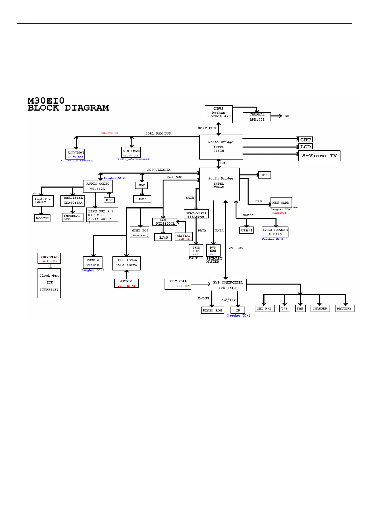
2.1 System Block Diagram
TECHNICAL SERVICE MANUALPrestigio Visconte 130
29
Page 30
TECHNICAL SERVICE MANUAL Prestigio Visconte 130
2.2 Major Components
CPU Banias/Celeron (U37A)
U37A
P4
U4
V3
R3
V2
W1
T4
W2
Y4
Y1
U1
AA3
Y3
AA2
U3
R2
P3
T2
P1
T1
AF4
AC4
AC7
AC3
AD3
AE4
AD2
AB4
AC6
AD5
AE2
AD6
AF3
AE1
AF1
AE5
C2
D3
A3
C6
D1
D4
B4
A3#
A4#
A5#
ADDR GROUP 0 ADDR GROUP 1
A6#
A7#
A8#
A9#
A10#
A11#
A12#
A13#
A14#
A15#
A16#
ADSTB#0
REQ0#
REQ1#
REQ2#
REQ3#
REQ4#
A17#
A18#
A19#
A20#
A21#
A22#
A23#
A24#
A25#
A26#
A27#
A28#
A29#
A30#
A31#
ADSTB#1
A20M#
FERR#
IGNNE#
STPCLK#
LINT0
LINT1
SMI#
ADS#
BNR#
BPRI#
DEFER#
DRDY#
DBSY#
BR0#
IERR#
INIT#
CONTROLITP SIGNALSTHERMH CLK
LOCK#
RESET#
RS0#
RS1#
RS2#
TRDY#
HIT#
HITM#
BPM#0
BPM#1
BPM#2
BPM#3
PRDY#
PREQ#
TCK
TDI
TDO
TMS
TRST#
DBR#
PROCHOT#
THERMDA
THERMDC
THERMTRIP#
ITP_CLK1
ITP_CLK0
BCLK1
BCLK0
N2
L1
J3
L4
H2
M2
N4
A4
B5
J2
B11
H1
K1
L2
M3
K3
K4
C8
B8
A9
C9
A10
B10
A13
C12
A12
C11
B13
A7
B17
B18
A18
C17
A15
A16
B14
B15
CPU Banias/Celeron (U37B)
30
Page 31

TECHNICAL SERVICE MANUALPrestigio Visconte 130
U37B
A19
A25
A22
B21
A24
B26
A21
B20
C20
B24
D24
E24
C26
B23
E23
C25
C23
C22
D25
H23
G25
L23
M26
H24
F25
G24
J23
M23
J25
L26
N24
M25
H26
N25
K25
K24
L24
J26
E1
C16
C14
B2
C3
AF7
AC1
E26
AD26
D0#
D1#
D2#
D3#
D4#
D5#
D6#
D7#
D8#
D9#
D10#
D11#
D12#
D13#
D14#
D15#
DSTBN0#
DSTBP0#
DINV0#
D16#
D17#
D18#
D19#
D20#
D21#
D22#
D23#
D24#
D25#
D26#
D27#
D28#
D29#
D30#
D31#
DSTBN1#
DSTBP1#
DINV1#
PSI#
BSEL0
BSEL1
NC1
RSVD2
RSVD3
RSVD4
RSVD5
GTLREF0
DATA GRP0
DATA GRP2
DSTBN2#
DSTBP2#
DINV2#
DATA GRP1
DATA GRP3
DSTBN3#
DSTBP3#
DINV3#
COMP0
COMP1
COMP2
MISC
COMP3
DPRSTP#
DPSLP#
DPWR#
PWRGOOD
D32#
D33#
D34#
D35#
D36#
D37#
D38#
D39#
D40#
D41#
D42#
D43#
D44#
D45#
D46#
D47#
D48#
D49#
D50#
D51#
D52#
D53#
D54#
D55#
D56#
D57#
D58#
D59#
D60#
D61#
D62#
D63#
SLP#
TEST1
TEST2
Y26
AA24
T25
U23
V23
R24
R26
R23
AA23
U26
V24
U25
V26
Y23
AA26
Y25
W25
W24
T24
AB25
AC23
AB24
AC20
AC22
AC25
AD23
AE22
AF23
AD24
AF20
AE21
AD21
AF25
AF22
AF26
AE24
AE25
AD20
P25
P26
AB2
AB1
G1
B7
C19
E4
A6
C5
F23
CPU Banias/Celeron (U37C)
31
Page 32

TECHNICAL SERVICE MANUAL Prestigio Visconte 130
U37C
AA11
AA13
AA15
AA17
AA19
AA21
AA5
AA7
AA9
AB10
AB12
AB14
AB16
AB18
AB20
AB22
AB6
AB8
AC11
AC13
AC15
AC17
AC19
AC9
AD10
AD12
AD14
AD16
AD18
AD8
AE11
AE13
AE15
AE17
AE19
AE9
AF10
AF12
AF14
AF16
AF18
AF8
D18
D20
D22
D6
D8
E17
E19
E21
E5
E7
E9
F18
F20
F22
F6
F8
G21
VCC0
VCC1
VCC2
VCC3
VCC4
VCC5
VCC6
VCC7
VCC8
VCC9
VCC10
VCC11
VCC12
VCC13
VCC14
VCC15
VCC16
VCC17
VCC18
VCC19
VCC20
VCC21
VCC22
VCC23
VCC24
VCC25
VCC26
VCC27
VCC28
VCC29
VCC30
VCC31
VCC32
VCC33
VCC34
VCC35
VCC36
VCC37
VCC38
VCC39
VCC40
VCC41
VCC42
VCC43
VCC44
VCC45
VCC46
VCC47
VCC48
VCC49
VCC50
VCC51
VCC52
VCC53
VCC54
VCC55
VCC56
VCC57
VCC58
VCC59
VCC60
VCC61
VCC62
VCC63
VCC64
VCC65
VCC66
VCC67
VCC68
VCC69
VCC70
VCC71
VCCA0
VCCA1
VCCA2
VCCA3
VCCP0
VCCP1
VCCP2
VCCP3
VCCP4
VCCP5
VCCP6
VCCP7
POWER
VCCP8
VCCP9
VCCP10
VCCP11
VCCP12
VCCP13
VCCP14
VCCP15
VCCP16
VCCP17
VCCP18
VCCP19
VCCP20
VCCP21
VCCP22
VCCP23
VCCP24
VCCQ0
VCCQ1
VCCSENSE
VSSSENSE
VID0
VID1
VID2
VID3
VID4
VID5
G5
H22
H6
J21
J5
K22
U5
V22
V6
W21
W5
Y22
Y6
F26
B1
N1
AC26
D10
D12
D14
D16
E11
E13
E15
F10
F12
F14
F16
K6
L21
L5
M22
M6
N21
N5
P22
P6
R21
R5
T22
T6
U21
P23
W4
E2
F2
F3
G3
G4
H4
AE7
AF6
32
Page 33

CPU Banias/Celeron (U37D)
AC10
AC12
AC14
AC16
AC18
AC21
AC24
AD11
AD13
AD15
AD17
AD19
AD22
AD25
A11
A14
A17
A20
A23
A26
AA1
AA4
AA6
AA8
AA10
AA12
AA14
AA16
AA18
AA20
AA22
AA25
AB3
AB5
AB7
AB9
AB11
AB13
AB15
AB17
AB19
AB21
AB23
AB26
AC2
AC5
AC8
AD1
AD4
AD7
AD9
AE3
AE6
AE8
AE10
AE12
AE14
AE16
AE18
AE20
AE23
AE26
AF2
AF5
AF9
AF11
AF13
AF15
AF17
AF19
AF21
AF24
B12
B16
B19
B22
B25
C10
C13
C15
C18
C21
C24
D11
TECHNICAL SERVICE MANUALPrestigio Visconte 130
U37D
A2
VSS0
A5
VSS1
A8
VSS2
VSS3
VSS4
VSS5
VSS6
VSS7
VSS8
VSS9
VSS10
VSS11
VSS12
VSS13
VSS14
VSS15
VSS16
VSS17
VSS18
VSS19
VSS20
VSS21
VSS22
VSS23
VSS24
VSS25
VSS26
VSS27
VSS28
VSS29
VSS30
VSS31
VSS32
VSS33
VSS34
VSS35
VSS36
VSS37
VSS38
VSS39
VSS40
VSS41
VSS42
VSS43
VSS44
VSS45
VSS46
VSS47
VSS48
VSS49
VSS50
VSS51
VSS52
VSS53
VSS54
VSS55
VSS56
VSS57
VSS58
VSS59
VSS60
VSS61
VSS62
VSS63
VSS64
VSS65
VSS66
VSS67
VSS68
VSS69
VSS70
VSS71
VSS72
VSS73
VSS74
B3
VSS75
B6
VSS76
B9
VSS77
VSS78
VSS79
VSS80
VSS81
VSS82
C1
VSS83
C4
VSS84
C7
VSS85
VSS86
VSS87
VSS88
VSS89
VSS90
VSS91
D2
VSS92
D5
VSS93
D7
VSS94
D9
VSS95
VSS96
VSS100
VSS101
VSS102
VSS103
VSS104
VSS105
VSS106
VSS107
VSS108
VSS109
VSS110
VSS111
VSS112
VSS113
VSS114
VSS115
VSS116
VSS117
VSS118
VSS119
VSS120
VSS121
VSS122
VSS123
VSS124
VSS125
VSS126
VSS127
VSS128
VSS129
VSS130
VSS131
VSS132
VSS133
VSS134
VSS135
VSS136
VSS137
VSS138
VSS139
VSS140
VSS141
VSS142
VSS143
VSS
VSS144
VSS145
VSS146
VSS147
VSS148
VSS149
VSS150
VSS151
VSS152
VSS153
VSS154
VSS155
VSS156
VSS157
VSS158
VSS159
VSS160
VSS161
VSS162
VSS163
VSS164
VSS165
VSS166
VSS167
VSS168
VSS169
VSS170
VSS171
VSS172
VSS173
VSS174
VSS175
VSS176
VSS177
VSS178
VSS179
VSS180
VSS181
VSS182
VSS183
VSS184
VSS185
VSS186
VSS187
VSS188
VSS189
VSS190
VSS191
VSS97
VSS98
VSS99
D13
D15
D17
D19
D21
D23
D26
E3
E6
E8
E10
E12
E14
E16
E18
E20
E22
E25
F1
F4
F5
F7
F9
F11
F13
F15
F17
F19
F21
F24
G2
G6
G22
G23
G26
H3
H5
H21
H25
J1
J4
J6
J22
J24
K2
K5
K21
K23
K26
L3
L6
L22
L25
M1
M4
M5
M21
M24
N3
N6
N22
N23
N26
P2
P5
P21
P24
R1
R4
R6
R22
R25
T3
T5
T21
T23
T26
U2
U6
U22
U24
V1
V4
V5
V21
V25
W3
W6
W22
W23
W26
Y2
Y5
Y21
Y24
33
Page 34

TECHNICAL SERVICE MANUAL Prestigio Visconte 130
Intel 915GM (Alviso) (U34A)
U34A
E4
E1
F4
H7
E2
F1
E3
D3
K7
F2
H6
F3
K8
H5
H1
H2
K5
K6
G3
H3
K4
P7
P5
U7
V6
R6
R5
P3
R7
R8
U8
R4
R1
V8
U6
W6
U3
V5
W8
W7
U2
U1
Y5
Y2
V4
Y7
W1
W3
Y3
Y6
W2
C1
C2
D1
P1
J7
J8
J4
J1
L5
J5
L7
J3
L3
T8
T4
T5
T3
T1
L1
HD0#
HD1#
HD2#
HD3#
HD4#
HD5#
HD6#
HD7#
HD8#
HD9#
HD10#
HD11#
HD12#
HD13#
HD14#
HD15#
HD16#
HD17#
HD18#
HD19#
HD20#
HD21#
HD22#
HD23#
HD24#
HD25#
HD26#
HD27#
HD28#
HD29#
HD30#
HD31#
HD32#
HD33#
HD34#
HD35#
HD36#
HD37#
HD38#
HD39#
HD40#
HD41#
HD42#
HD43#
HD44#
HD45#
HD46#
HD47#
HD48#
HD49#
HD50#
HD51#
HD52#
HD53#
HD54#
HD55#
HD56#
HD57#
HD58#
HD59#
HD60#
HD61#
HD62#
HD63#
HXRCOMP
HXSCOMP
HXSWING
HYRCOMP
HYSCOMP
HYSWING
HOST
HA10#
HA11#
HA12#
HA13#
HA14#
HA15#
HA16#
HA17#
HA18#
HA19#
HA20#
HA21#
HA22#
HA23#
HA24#
HA25#
HA26#
HA27#
HA28#
HA29#
HA30#
HA31#
HADS#
HADSTB#0
HADSTB#1
HVREF
HBNR#
HBPRI#
HBREQ0#
HCPURST#
HCLKINN
HCLKINP
HDBSY#
HDEFER#
HDINV#0
HDINV#1
HDINV#2
HDINV#3
HDPWR#
HDRDY#
HDSTBN#0
HDSTBN#1
HDSTBN#2
HDSTBN#3
HDSTBP#0
HDSTBP#1
HDSTBP#2
HDSTBP#3
HEDRDY#
HHITM#
HLOCK#
HPCREQ#
HREQ#0
HREQ#1
HREQ#2
HREQ#3
HREQ#4
HRS0#
HRS1#
HRS2#
HCPUSLP#
HTRDY#
HA3#
HA4#
HA5#
HA6#
HA7#
HA8#
HA9#
HHIT#
G9
C9
E9
B7
A10
F9
D8
B10
E10
G10
D9
E11
F10
G11
G13
C10
C11
D11
C12
B13
A12
F12
G12
E12
C13
B11
D13
A13
F13
F8
B9
E13
J11
A5
D5
E7
H10
AB1
AB2
C6
E6
H8
K3
T7
U5
G6
F7
G4
K1
R3
V3
G5
K2
R2
W4
F6
D4
D6
B3
A11
A7
D7
B8
C7
A8
A4
C5
B4
G8
B5
ALVISO_90
Intel 915GM (Alviso) (U34B)
34
Page 35

TECHNICAL SERVICE MANUALPrestigio Visconte 130
U34B
AA31
AB35
AC31
AD35
Y31
AA35
AB31
AC35
AA33
AB37
AC33
AD37
Y33
AA37
AB33
AC37
AM33
AL1
AJ34
AF6
AN33
AK1
AJ33
AF5
AP21
AM21
AH21
AK21
AN16
AM14
AH15
AG16
AF22
AF16
DMIRXN0
DMIRXN1
DMIRXN2
DMIRXN3
DMIRXP0
DMIRXP1
DMIRXP2
DMIRXP3
DMITXN0
DMITXN1
DMITXN2
DMITXN3
DMITXP0
DMITXP1
DMITXP2
DMITXP3
SM_CK0
SM_CK1
SM_CK3
SM_CK4
SM_CK0#
SM_CK1#
SM_CK3#
SM_CK4#
SM_CKE0
SM_CKE1
SM_CKE2
SM_CKE3
SM_CS0#
SM_CS1#
SM_CS2#
SM_CS3#
SM_OCDCOMP0
SM_OCDCOMP1
CFG0
CFG1
CFG2
CFG3
CFG4
CFG5
CFG6
CFG7
CFG8
CFG9
CFG10
CFG11
CFG12
DMI
DDR MUXING
DREF_SSCLKN
DREF_SSCLKP
CFG13
CFG/RSVD
CFG14
CFG15
CFG16
CFG17
CFG18
CFG19
CFG20
RSVD21
RSVD22
RSVD23
RSVD24
RSVD25
RSVD26
RSVD27
RSVD28
RSVD29
RSVD30
RSVD31
BM_BUSY#
EXT_TS0#
EXT_TS1#
THRMTRIP#
PM
PWROK
RSTIN#
DREF_CLKN
DREF_CLKP
G16
H13
G14
F16
F15
G15
E16
D17
J16
D15
E15
D14
E14
H12
C14
H15
J15
H14
G22
G23
D23
G25
G24
J17
A31
A30
D26
D25
AE11
AE10
AC10
AD10
J23
J21
H22
F5
AD30
AE29
A24
A23
C37
D37
AP14
SM_ODT0
AL15
SM_ODT1
AM11
SM_ODT2
AN10
SM_ODT3
AK10
SMRCOMPN
AK11
SMRCOMPP
AF37
SMVREF0
AD1
SMVREF1
AE27
SMXSLEWIN
AE28
SMXSLEWOUT
AF9
SMYSLEWIN
AF10
SMYSLEWOUT
Intel 915GM (Alviso) (U34C)
ALVISO_90
35
CLK
NC
NC1
NC2
NC3
NC4
NC5
NC6
NC7
NC8
NC9
NC10
NC11
AP37
AN37
AP36
AP2
AP1
AN1
B1
A2
B37
A36
A37
Page 36

TECHNICAL SERVICE MANUAL Prestigio Visconte 130
U34C
AG35
AH35
AL35
AL37
AH36
AJ35
AK37
AL34
AM36
AN35
AP32
AM31
AM34
AM35
AL32
AM32
AN31
AP31
AN28
AP28
AL30
AM30
AM28
AL28
AP27
AM27
AM23
AM22
AL23
AM24
AN22
AP22
AM9
AL9
AL6
AP7
AP11
AP10
AL7
AM7
AN5
AN6
AN3
AP3
AP6
AM6
AL4
AM3
AK2
AK3
AG2
AG1
AL3
AM2
AH3
AG3
AF3
AE3
AD6
AC4
AF2
AF1
AD4
AD5
SADQ0
SADQ1
SADQ2
SADQ3
SADQ4
SADQ5
SADQ6
SADQ7
SADQ8
SADQ9
SADQ10
SADQ11
SADQ12
SADQ13
SADQ14
SADQ15
SADQ16
SADQ17
SADQ18
SADQ19
SADQ20
SADQ21
SADQ22
SADQ23
SADQ24
SADQ25
SADQ26
SADQ27
SADQ28
SADQ29
SADQ30
SADQ31
SADQ32
SADQ33
SADQ34
SADQ35
SADQ36
SADQ37
SADQ38
SADQ39
SADQ40
SADQ41
SADQ42
SADQ43
SADQ44
SADQ45
SADQ46
SADQ47
SADQ48
SADQ49
SADQ50
SADQ51
SADQ52
SADQ53
SADQ54
SADQ55
SADQ56
SADQ57
SADQ58
SADQ59
SADQ60
SADQ61
SADQ62
SADQ63
SA_BS0#
SA_BS1#
SA_BS2#
SA_DM0
SA_DM1
SA_DM2
SA_DM3
SA_DM4
SA_DM5
SA_DM6
SA_DM7
SA_DQS0
SA_DQS1
SA_DQS2
SA_DQS3
SA_DQS4
SA_DQS5
SA_DQS6
SA_DQS7
SA_DQS0#
SA_DQS1#
SA_DQS2#
SA_DQS3#
SA_DQS4#
SA_DQS5#
SA_DQS6#
SA_DQS7#
SA_MA0
SA_MA1
SA_MA2
SA_MA3
SA_MA4
SA_MA5
SA_MA6
SA_MA7
SA_MA8
SA_MA9
SA_MA10
SA_MA11
SA_MA12
SA_MA13
DDR SYSTEM MEMORY A
SA_CAS#
SA_RAS#
SA_RCVENIN#
SA_RCVENOUT#
SA_WE#
AK15
AK16
AL21
AJ37
AP35
AL29
AP24
AP9
AP4
AJ2
AD3
AK36
AP33
AN29
AP23
AM8
AM4
AJ1
AE5
AK35
AP34
AN30
AN23
AN8
AM5
AH1
AE4
AL17
AP17
AP18
AM17
AN18
AM18
AL19
AP20
AM19
AL20
AM16
AN20
AM20
AM15
AN15
AP16
AF29
AF28
AP15
ALVISO_90
Intel 915GM (Alviso) (U34D)
36
Page 37

AE31
AE32
AG32
AG36
AE34
AE33
AF31
AF30
AH33
AH32
AK31
AG30
AG34
AG33
AH31
AJ31
AK30
AJ30
AH29
AH28
AK29
AH30
AH27
AG28
AF24
AG23
AJ22
AK22
AH24
AH23
AG22
AJ21
AG10
AG9
AG8
AH8
AH11
AH10
AJ9
AK9
AJ7
AK6
AJ4
AH5
AK8
AJ8
AJ5
AK4
AG5
AG4
AD8
AD9
AH4
AG6
AE8
AD7
AC5
AB8
AB6
AA8
AC8
AC7
AA4
AA5
U34D
SBDQ0
SBDQ1
SBDQ2
SBDQ3
SBDQ4
SBDQ5
SBDQ6
SBDQ7
SBDQ8
SBDQ9
SBDQ10
SBDQ11
SBDQ12
SBDQ13
SBDQ14
SBDQ15
SBDQ16
SBDQ17
SBDQ18
SBDQ19
SBDQ20
SBDQ21
SBDQ22
SBDQ23
SBDQ24
SBDQ25
SBDQ26
SBDQ27
SBDQ28
SBDQ29
SBDQ30
SBDQ31
SBDQ32
SBDQ33
SBDQ34
SBDQ35
SBDQ36
SBDQ37
SBDQ38
SBDQ39
SBDQ40
SBDQ41
SBDQ42
SBDQ43
SBDQ44
SBDQ45
SBDQ46
SBDQ47
SBDQ48
SBDQ49
SBDQ50
SBDQ51
SBDQ52
SBDQ53
SBDQ54
SBDQ55
SBDQ56
SBDQ57
SBDQ58
SBDQ59
SBDQ60
SBDQ61
SBDQ62
SBDQ63
TECHNICAL SERVICE MANUALPrestigio Visconte 130
SB_BS0#
SB_BS1#
SB_BS2#
SB_DM0
SB_DM1
SB_DM2
SB_DM3
SB_DM4
SB_DM5
SB_DM6
SB_DM7
SB_DQS0
SB_DQS1
SB_DQS2
SB_DQS3
SB_DQS4
SB_DQS5
SB_DQS6
SB_DQS7
SB_DQS0#
SB_DQS1#
SB_DQS2#
SB_DQS3#
SB_DQS4#
SB_DQS5#
SB_DQS6#
SB_DQS7#
SB_MA0
SB_MA1
SB_MA2
SB_MA3
SB_MA4
SB_MA5
SB_MA6
SB_MA7
SB_MA8
SB_MA9
SB_MA10
SB_MA11
SB_MA12
SB_MA13
SB_CAS#
DDR SYSTEM MEMORY B
SB_RAS#
SB_RCVENIN#
SB_RCVENOUT#
SB_WE#
AJ15
AG17
AG21
AF32
AK34
AK27
AK24
AJ10
AK5
AE7
AB7
AF34
AK32
AJ28
AK23
AM10
AH6
AF8
AB4
AF35
AK33
AK28
AJ23
AL10
AH7
AF7
AB5
AH17
AK17
AH18
AJ18
AK18
AJ19
AK19
AH19
AJ20
AH20
AJ16
AG18
AG20
AG15
AH14
AK14
AF15
AF14
AH16
ALVISO_90
Intel 915GM (Alviso) (U34E)
37
Page 38

TECHNICAL SERVICE MANUAL Prestigio Visconte 130
U34E
T29
R29
N29
M29
K29
J29
V28
U28
T28
R28
P28
N28
M28
L28
K28
J28
H28
G28
V27
U27
T27
R27
P27
N27
M27
L27
K27
J27
H27
K26
H26
K25
J25
K24
K23
K22
K21
W20
U20
T20
K20
V19
U19
K19
W18
V18
T18
K18
K17
AC2
AC1
B23
C35
AA1
AA2
F19
E19
G19
H20
K13
J13
K12
W11
V11
U11
T11
R11
P11
N11
M11
L11
K11
W10
V10
U10
T10
R10
P10
N10
M10
K10
J10
Y9
W9
U9
R9
P9
N9
M9
L9
J9
N8
M8
N7
M7
N6
M6
A6
N5
M5
N4
M4
N3
M3
N2
M2
B2
V1
N1
M1
G1
VCC0
VCC1
VCC2
VCC3
VCC4
VCC5
VCC6
VCC7
VCC8
VCC9
VCC10
VCC11
VCC12
VCC13
VCC14
VCC15
VCC16
VCC17
VCC18
VCC19
VCC20
VCC21
VCC22
VCC23
VCC24
VCC25
VCC26
VCC27
VCC28
VCC29
VCC30
VCC31
VCC32
VCC33
VCC34
VCC35
VCC36
VCC37
VCC38
VCC39
VCC40
VCC41
VCC42
VCC43
VCC44
VCC45
VCC46
VCC47
VCC48
VCCH_MPLL1
VCCH_MPLL0
VCCA_DPLLA
VCCA_DPLLB
VCCA_HPLL
VCCA_MPLL
VCCA_CRTDAC0
VCCA_CRTDAC1
VSSA_CRTDAC
VCC_SYNC
VTT0
VTT1
VTT2
VTT3
VTT4
VTT5
VTT6
VTT7
VTT8
VTT9
VTT10
VTT11
VTT12
VTT13
VTT14
VTT15
VTT16
VTT17
VTT18
VTT19
VTT20
VTT21
VTT22
VTT23
VTT24
VTT25
VTT26
VTT27
VTT28
VTT29
VTT30
VTT31
VTT32
VTT33
VTT34
VTT35
VTT36
VTT37
VTT38
VTT39
VTT40
VTT41
VTT42
VTT43
VTT44
VTT45
VTT46
VTT47
VTT48
VTT49
VTT50
VTT51
ALVISO_90
VCCA_TVDACA0
VCCA_TVDACA1
VCCA_TVDACB0
VCCA_TVDACB1
VCCA_TVDACC0
VCCA_TVDACC1
VCCA_TVBG
VSSA_TVBG
VCCD_TVDAC
VCCDQ_TVDAC
VCCD_LVDS0
VCCD_LVDS1
VCCD_LVDS2
VCCA_LVDS
VSSALVDS
VCCSM10
VCCSM11
VCCSM12
VCCSM13
VCCSM14
VCCSM15
VCCSM16
VCCSM17
VCCSM18
VCCSM19
VCCSM20
VCCSM21
POWER
VCCSM22
VCCSM23
VCCSM24
VCCSM25
VCCSM26
VCCSM27
VCCSM28
VCCSM29
VCCSM30
VCCSM31
VCCSM32
VCCSM33
VCCSM34
VCCSM35
VCCSM36
VCCSM37
VCCSM38
VCCSM39
VCCSM40
VCCSM41
VCCSM42
VCCSM43
VCCSM44
VCCSM45
VCCSM46
VCCSM47
VCCSM48
VCCSM49
VCCSM50
VCCSM51
VCCSM52
VCCSM53
VCCSM54
VCCSM55
VCCSM56
VCCSM57
VCCSM58
VCCSM59
VCCSM60
VCCSM61
VCCSM62
VCCSM63
VCCSM64
VCCTX_LVDS0
VCCTX_LVDS1
VCCTX_LVDS2
VCCA_SM0
VCCA_SM1
VCCA_SM2
VCCA_SM3
VCCA_3GPLL0
VCCA_3GPLL1
VCCA_3GPLL2
VCCA_3GBG
VSSA_3GBG
VCCHV0
VCCHV1
VCCHV2
VCCSM0
VCCSM1
VCCSM2
VCCSM3
VCCSM4
VCCSM5
VCCSM6
VCCSM7
VCCSM8
VCCSM9
VCC3G0
VCC3G1
VCC3G2
VCC3G3
VCC3G4
VCC3G5
VCC3G6
F17
E17
D18
C18
F18
E18
H18
G18
D19
H17
B26
B25
A25
A35
B36
B22
B21
A21
AM37
AH37
AP29
AD28
AD27
AC27
AP26
AN26
AM26
AL26
AK26
AJ26
AH26
AG26
AF26
AE26
AP25
AN25
AM25
AL25
AK25
AJ25
AH25
AG25
AF25
AE25
AE24
AE23
AE22
AE21
AE20
AE19
AE18
AE17
AE16
AE15
AE14
AP13
AN13
AM13
AL13
AK13
AJ13
AH13
AG13
AF13
AE13
AP12
AN12
AM12
AL12
AK12
AJ12
AH12
AG12
AF12
AE12
AD11
AC11
AB11
AB10
AB9
AP8
AM1
AE1
B28
A28
A27
AF20
AP19
AF19
AF18
AE37
W37
U37
R37
N37
L37
J37
Y29
Y28
Y27
F37
G37
38
Page 39

TECHNICAL SERVICE MANUALPrestigio Visconte 130
Intel 915GM (Alviso) (U34F)
Intel 915GM (Alviso) (U34G)
39
Page 40

TECHNICAL SERVICE MANUAL Prestigio Visconte 130
Intel 915GM (Alviso) (U34H)
40
Page 41

TECHNICAL SERVICE MANUALPrestigio Visconte 130
41
Page 42

TECHNICAL SERVICE MANUAL Prestigio Visconte 130
Clock Gen (ICS954127)
7
U22
19
VDDSRC
28
VDD_PCIEX
34
VDD_PCIEX1
42
VDD_CPU
37
VDDA
38
GNDA
50
XTAL_IN
49
XTAL_OUT
12
FSA/USB_48
16
GND
8
FSC/PCICLK_F0
5
PCI3
4
PCI2
3
PCI1
56
PCICLK0~
9
FSB/PCICLK_F1
53
RTFS_0
46
SCLK
47
SDATA
39
IREF
13
VSS_48
29
VSS_PCIE
45
VSS_CPU
2
VSS_PCI
6
RESET#
51
VSS_REF
1
VDD_PCI1
VDD_PCI0
VTT_PWRGD#/PD
VDD_48
VDD_REF
RTFS_2
RTFS_1
CPUCLKT1
CPUCLKC1
CPUCLKT0
CPUCLKC0
PCIEXT6
PCIEXC6
PCIEXT5
PCIEXC5
PCIEXT4
PCIEXC4
PCIEXT3
PCIEXC3
PCIEXT2
PCIEXC2
PCIEXT1
PCIEXC1
PCIEXT0
PCIEXC0
SRC0
SRC0#
DOT96
DOT96#
REFOUT
11
48
55
54
41
40
44
43
36
35
33
32
31
30
26
27
24
25
22
23
20
21
17
18
14
15
10
52
ICS 954127
42
Page 43

TECHNICAL SERVICE MANUALPrestigio Visconte 130
SB ICH-6M (U19A)
43
Page 44

TECHNICAL SERVICE MANUAL Prestigio Visconte 130
SB ICH-6M (U19B)
U19B
E2
E5
C2
F5
F3
E9
F2
D6
E6
D3
A2
D2
D5
H3
B4
J5
K2
K5
D4
L6
G3
H4
H2
H5
B3
M6
B2
K6
K3
A5
L1
K4
J3
N2
L2
M1
L3
AC5
AD5
AF4
AG4
AC9
AD[0]
AD[1]
AD[2]
AD[3]
AD[4]
AD[5]
AD[6]
AD[7]
AD[8]
AD[9]
AD[10]
AD[11]
AD[12]
AD[13]
AD[14]
AD[15]
AD[16]
AD[17]
AD[18]
AD[19]
AD[20]
AD[21]
AD[22]
AD[23]
AD[24]
AD[25]
AD[26]
AD[27]
AD[28]
AD[29]
AD[30]
AD[31]
FRAME#
Interrupt I/ F
PIRQ[A]#
PIRQ[B]#
PIRQ[C]#
PIRQ[D]#
RESERVED
RSVD[1]
RSVD[2]
RSVD[3]
RSVD[4]
RSVD[5]
ICH-6_M
REQ[0]#
PCI
REQ[4]#/GPI[40]
GNT[4]#/GPO[48]
GNT[5]#/GPO[17]
GNT[6]#/GPO[16]
PIRQ[G]#/GPI[4]
PIRQ[H]#/GPI[5]
GNT[0]#
REQ[1]#
GNT[1]#
REQ[2]#
GNT[2]#
REQ[3]#
GNT[3]#
REQ[5]#/GPI[1]
REQ[6]#/GPI[0]
C/BE[0]#
C/BE[1]#
C/BE[2]#
C/BE[3]#
IRDY#
PCIRST#
DEVSEL#
PERR#
PLOCK#
SERR#
STOP#
TPDY#
PLTRST#
PCICLK
PME#
PIRQ[E]#/GPI[2]
PIRQ[F]#/GPI[3]
RSVD[6]
RSVD[7]
RSVD[8]
RSVD[9]
PAR
L5
C1
B5
B6
M5
F1
B8
C8
F7
E7
E8
F6
B7
D8
J6
H6
G4
G2
A3
E1
R2
C3
E3
C5
G5
J1
J2
R5
G6
P6
D9
C7
C6
M3
AD9
AF8
AG8
U3
SB ICH-6M (U19C)
44
Page 45

U19C
T2
RI#
AF17
SATA[0]GP/GPIO[26]
AE18
SATA[1]GP/GPIO[29]
AF18
SATA[2]GP/GPIO[30]
AG18
SATA[3]GP/GPIO[31]
Y4
SMBCLK
W5
SMBDATA
Y5
LINKALERT#
W4
SMLINK[0]
U6
SMLINK[1]
AG21
MCH_SYNC#
F8
SPKR
W3
SUS_STAT#/LPCPD#
U2
SYS_RESET#
AD19
BM_BUSY#/GPI[6]
AE19
GP[7]
R1
GP[8]
W6
SMBALERT#/GPI[11]
M2
GPI[12]
R6
GPI[13]
AC21
STP_PCI#/GPO[18]
AB21
GPO[19]
AD22
STP_CPU#/GPO[20]
AD20
GPO[21]
AD21
GPO[23]
V3
GPIO[24]
P5
GPIO[25]
R3
GPIO[27]
T3
GPIO[28]
AF19
CLKRUN#/GPIO[32]
AF20
GPIO[33]
AC18
GPIO[34]
U5
WAKE#
AB20
SERIRQ
AC20
THRM#
AF21
VRMPWRGD
E10
CLK14
A27
CLK48
V6
SUSCK
T4
SLP_S3#
T5
SLP_S4#
T6
SLP_S5#
AA1
PWROK
AE20
DPRSLPVR/TP[1]
V2
BATLOW#/TP[0]
U1
PWRBTN#
V5
LAN_RST#
Y3
RSMRST#
ICH-6_M
HSIN[0]
HSIP[0]
HSON[0]
HSOP[0]
HSIN[1]
HSIP[1]
HSON[1]
HSOP[1]
HSIN[2]
HSIP[2]
GPIO
POWER MGT CLOCKS
HSON[2]
HSOP[2]
HSIN[3]
HSIP[3]
HSON[3]
HSOP[3]
DMI[0]RXN
DMI[0]RXP
DMI[0]TXN
DMI[0]TXP
DMI[1]RXN
DMI[1]RXP
DMI[1]TXN
DMI[1]TXP
DMI[2]RXN
DMI[2]RXP
DMI[2]TXN
DMI[2]TXP
DMI[3]RXN
DMI[3]RXP
DMI[3]TXN
DMI[3]TXP
Direct Media Interface PCI-EXPRESS
DMI_CLKN
DMI_CLKP
DMI_ZCOMP
DMI_IRCOMP
OC[4]#/GPI[9]
OC[5]#/GPI[10]
OC[6]#/GPI[14]
OC[7]#/GPI[15]
OC[0]#
OC[1]#
OC[2]#
OC[3]#
USUP[0]N
USUP[0]P
USUP[1]N
USUP[1]P
USUP[2]N
USUP[2]P
USUP[3]N
USUP[3]P
USUP[4]N
USUP[4]P
USB
USUP[5]N
USUP[5]P
USUP[6]N
USUP[6]P
USUP[7]N
USUP[7]P
USBRBIAS#
USBRBIAS
TECHNICAL SERVICE MANUALPrestigio Visconte 130
H25
H24
G27
G26
K25
K24
J27
J26
M25
M24
L27
L26
P24
P23
N27
N26
T25
T24
R27
R26
V25
V24
U27
U26
Y25
Y24
W27
W26
AB24
AB23
AA27
AA26
AD25
AC25
F24
F23
C23
D23
C25
C24
C27
B27
B26
C26
C21
D21
A20
B20
D19
C19
A18
B18
E17
D17
B16
A16
C15
D15
A14
B14
A22
B22
45
Page 46
TECHNICAL SERVICE MANUAL Prestigio Visconte 130
SB ICH-6M (U19D)
U19D
Y1
Y2
AA2
AA3
AA5
D12
B12
D11
F13
F12
B11
E12
E11
C13
C12
C11
E13
C10
B9
A10
F11
F10
B10
C9
RTCX1
RTCX2
RTCRST#
INTRUDER#
INTVRMEN
EE_CS
EE_SHCLK
EE_DOUT
EE_DIN
LAN RTC
LAN_CLK
LAN_RSTSYNC
LANRXD[0]
LANRXD[1]
LANRXD[2]
LANTXD[0]
LANTXD[1]
LANTXD[2]
ACZ_BIT_CLK
ACZ_SYNC
ACZ_RST#
ACZ_SDIN[0]
ACZ_SDIN[1]
ACZ_SDIN[2]
ACZ_SDO
LAD[0]
LAD[1]/FB[1]
LAD[2]/FB[2]
LAD[3]/FB[3]
LPC
LDRQ[1]#/GPI[41]
CPUPWRGD/GPO[49]
LDRQ[0]#
LFRAME#
A20GATE
A20M#
CPUSLP#
DPRSTP#/TP[4]
DPSLP#/TP[2]
FERR#
IGNNE#
INT3_3V#
INTR
RCIN#
STPCLK#
THRMTRIP#
INT#
NMI
SMI#
P2
N3
N5
N4
N6
P4
P3
AF22
AF23
AE27
AE24
AD27
AF24
AG25
AG26
AE22
AF27
AG24
AD23
AF25
AG27
AE26
AE23
AC19
AE3
AD3
AG2
AF2
AD7
AC7
AF6
AG6
AC2
AC1
AG11
AF11
AF16
AB16
AB15
AC14
AE16
SATALED#
SATA[0]RXN
SATA[0]RXP
SATA[0]TXN
SATA[0]TXP
SATA[2]RXN
SATA[2]RXP
SATA[2]TXN
SATA[2]TXP
SATA_CLKN
SATA_CLKP
SATARBIAS#
SATARBIAS
IORDY
IDEIRQ
DDACK#
DIOW#
DIOR#
ICH-6_M
SATA AC-97/AZALIA CPU
IDE
DA[0]
DA[1]
DA[2]
DCS1#
DCS3#
DD[0]
DD[1]
DD[2]
DD[3]
DD[4]
DD[5]
DD[6]
DD[7]
DD[8]
DD[9]
DD[10]
DD[11]
DD[12]
DD[13]
DD[14]
DD[15]
DDREQ
AC16
AB17
AC17
AD16
AE17
AD14
AF15
AF14
AD12
AE14
AC11
AD11
AB11
AE13
AF13
AB12
AB13
AC13
AE15
AG15
AD13
AB14
46
Page 47

SB ICH-6M (U19E)
U19E
AA22
VCC1_5[1]
AA23
VCC1_5[2]
AA24
VCC1_5[3]
AA25
VCC1_5[4]
AB25
VCC1_5[5]
AB26
VCC1_5[6]
AB27
VCC1_5[7]
F25
VCC1_5[8]
F26
VCC1_5[9]
F27
VCC1_5[10]
G22
VCC1_5[11]
G23
G24
G25
H21
H22
J21
J22
K21
K22
L21
L22
M21
M22
N21
N22
N23
N24
N25
P21
P25
P26
P27
R21
R22
T21
T22
U21
U22
V21
V22
W21
W22
Y21
Y22
AA6
AB4
AB5
AB6
AC4
AD4
AE4
AE5
AF5
AG5
AA7
AA8
AA9
AB8
AC8
AD8
AE8
AE9
AF9
AG9
AC27
E26
AE1
AG10
A13
F14
G13
G14
A11
U4
V1
V7
W2
Y7
A17
B17
C17
F18
G17
G18
VCC1_5[12]
VCC1_5[13]
VCC1_5[14]
VCC1_5[15]
VCC1_5[16]
VCC1_5[17]
VCC1_5[18]
VCC1_5[19]
VCC1_5[20]
VCC1_5[21]
VCC1_5[22]
VCC1_5[23]
VCC1_5[24]
VCC1_5[25]
VCC1_5[26]
VCC1_5[27]
VCC1_5[28]
VCC1_5[29]
VCC1_5[30]
VCC1_5[31]
VCC1_5[32]
VCC1_5[33]
VCC1_5[34]
VCC1_5[35]
VCC1_5[36]
VCC1_5[37]
VCC1_5[38]
VCC1_5[39]
VCC1_5[40]
VCC1_5[41]
VCC1_5[42]
VCC1_5[43]
VCC1_5[44]
VCC1_5[45]
VCC1_5[46]
VCC1_5[47]
VCC1_5[48]
VCC1_5[49]
VCC1_5[50]
VCC1_5[51]
VCC1_5[52]
VCC1_5[53]
VCC1_5[54]
VCC1_5[55]
VCC1_5[56]
VCC1_5[57]
VCC1_5[58]
VCC1_5[59]
VCC1_5[60]
VCC1_5[61]
VCC1_5[62]
VCC1_5[63]
VCC1_5[64]
VCC1_5[65]
VCCDMIPLL
VCC3_3[1]
VCCSATAPLL
VCC3_3[22]
VCCLAN3_3/VCCSUS3_3[1]
VCCLAN3_3/VCCSUS3_3[2]
VCCLAN3_3/VCCSUS3_3[3]
VCCLAN3_3/VCCSUS3_3[4]
VCCSUS3_3[1]
VCCSUS3_3[2]
VCCSUS3_3[3]
VCCSUS3_3[4]
VCCSUS3_3[5]
VCCSUS3_3[6]
VCCSUS3_3[7]
VCCSUS3_3[8]
VCCSUS3_3[9]
VCCSUS3_3[10]
VCCSUS3_3[11]
VCCSUS3_3[12]
ICH-6_M
PCIE
SATA
VCCLAN1_5/VCCSUS1_5[2]
VCCLAN1_5/VCCSUS1_5[1]
COREIDEPCI
VCCSUS1_5[3]
VCCSUS1_5[2]
VCCSUS1_5[1]
USBUSB CORE
PCI/IDE
REF
VCCSUS3_3[20]
VCCSUS3_3[19]
VCCSUS3_3[18]
VCCSUS3_3[17]
VCCSUS3_3[16]
VCCSUS3_3[15]
VCCSUS3_3[14]
VCCSUS3_3[13]
VCC1_5[98]
VCC1_5[97]
VCC1_5[96]
VCC1_5[95]
VCC1_5[94]
VCC1_5[93]
VCC1_5[92]
VCC1_5[91]
VCC1_5[90]
VCC1_5[89]
VCC1_5[88]
VCC1_5[87]
VCC1_5[86]
VCC1_5[85]
VCC1_5[84]
VCC1_5[83]
VCC1_5[82]
VCC1_5[81]
VCC1_5[80]
VCC1_5[79]
VCC3_3[21]
VCC3_3[20]
VCC3_3[19]
VCC3_3[18]
VCC3_3[17]
VCC3_3[16]
VCC3_3[15]
VCC3_3[14]
VCC3_3[13]
VCC3_3[12]
VCC3_3[11]
VCC3_3[10]
VCC3_3[9]
VCC3_3[8]
VCC3_3[7]
VCC3_3[6]
VCC3_3[5]
VCC3_3[4]
VCC3_3[3]
VCC3_3[2]
VCC1_5[78]
VCC1_5[77]
VCC1_5[76]
VCC1_5[75]
VCC1_5[74]
VCC1_5[73]
VCC1_5[72]
VCC1_5[71]
VCC1_5[70]
VCC1_5[69]
VCC1_5[68]
VCC1_5[67]
VCC2_5[4]
VCC2_5[2]
V5REF[2]
V5REF[1]
V5REF_SUS
VCCUSBPLL
VCCRTC
V_CPU_IO[3]
V_CPU_IO[2]
V_CPU_IO[1]
F9
U17
U16
U14
U12
U11
T17
T11
P17
P11
M17
M11
L17
L16
L14
L12
L11
AA21
AA20
AA19
AA10
AG19
AG16
AG13
AD17
AC15
AA17
AA15
AA14
AA12
P1
M7
L7
L4
J7
H7
H1
E4
B1
A6
U7
R7
G19
G20
F20
E24
E23
E22
E21
E20
D27
D26
D25
D24
G8
AB18
P7
AA18
A8
F21
A25
A24
AB3
G11
G10
AG23
AD26
AB22
G16
G15
F16
F15
E16
D16
C16
TECHNICAL SERVICE MANUALPrestigio Visconte 130
47
Page 48

TECHNICAL SERVICE MANUAL Prestigio Visconte 130
LAN RTL8100CL (U18)
33
34
36
37
39
40
42
43
47
49
50
53
55
57
58
59
79
82
83
85
86
87
89
90
93
95
96
97
98
102
103
104
92
77
60
44
28
27
46
70
76
69
67
61
68
63
127
8
AD31
AD30
AD29
AD28
AD27
AD26
AD25
AD24
AD23
AD22
AD21
AD20
AD19
AD18
AD17
AD16
AD15
AD14
AD13
AD12
AD11
AD10
AD9
AD8
AD7
AD6
AD5
AD4
AD3
AD2
AD1
AD0
CBEN0
CBEN1
CBEN2
CBEN3
PCICLK
RSTN
IDSEL
PERRN
PAR
STOPN
TRDYN
FRAMEN
DEVSELN
IRDYN
RTSET
CTRL25
123254
AVDD25/NC
VDD25/VDD18
78
VDD25/VDD18
3
99
VDD25/VDD18
VDD25/VDD18
AVDD33/AVDD25
26
7
41
20
AVDD33/AVDD25
56718494107
VDD33
VDD33
VDD33
AVDD33/AVDD25
VDD33
VDD33
VDD33
VDD33
U18
TXD+/MDI[0]+
TXD-/MDI[0]-
RXIN+/MDI[1]+
RXIN-/MDI[1]-
EESEL
EECK
AUX_EEDI
EEDO
PMEN
SERRN
REQN
INTAN
GNTN
ISOLATEB#
LWAKE
LED0
LED1
LED2
NC1/VSS
NC2/AVDD33
NC7/AVDD25
NC11/VDD18
NC12/VDD18
NC15/VDD18
NC19/M66EN
NC20/VDD18
NC23/VDD18
NC25/AVDD33
NC26/CTRL18
NC27/VDD18CLKRUN
NC3
NC4/VSS
NC5/MDI[2]+
NC6/MDI[2]-
NC8/MDI[3]+
NC9/MDI3]-
NC10/GND
NC13/GND
NC14
NC16
NC17/GND
NC18
NC21/GND
NC22/LED3
NC24/GND
1
2
5
6
106
111
109
108
31
75
30
25
29
23
105
117
115
114
9
10
11
13
14
15
16
18
19
22
24
45
48
62
64
72
73
74
88
110
112
113
116
118
120
125
12665
GND
GND
GND
417213538525166808191
IEEE-1394 TSB43AB22A (U24)
GND
GND
GND
GND
GND
GND
GND
48
GND
100
GND
GND
101
119
GND
GND
123
124
GND
128
GND
121
X1
122
X2
RTL8100CL_LQFP
Page 49

U24
84
PCI_AD0
82
PCI_AD1
81
PCI_AD2
80
PCI_AD3
79
PCI_AD4
77
PCI_AD5
76
PCI_AD6
74
PCI_AD7
71
PCI_AD8
70
PCI_AD9
69
PCI_AD10
67
PCI_AD11
66
PCI_AD12
65
PCI_AD13
63
PCI_AD14
61
PCI_AD15
46
PCI_AD16
45
PCI_AD17
43
PCI_AD18
42
PCI_AD19
41
PCI_AD20
40
PCI_AD21
38
PCI_AD22
37
PCI_AD23
32
PCI_AD24
31
PCI_AD25
29
PCI_AD26
28
PCI_AD27
26
PCI_AD28
25
PCI_AD29
24
PCI_AD30
22
PCI_AD31
73
PCI_CBE0#
60
PCI_CBE1#
47
PCI_CBE2#
34
PCI_CBE3#
58
PCI_PAR
49
PCI_FRAME#
50
PCI_IRDY#
52
PCI_TRDY#
53
PCI_DEVSEL#
54
PCI_STOP#
36
PCI_IDSEL
19
PCI_REQ#
18
PCI_GNT#
56
PCI_PERR#
57
PCI_SERR#
16
PCI_CLK
12 91
PCI_CLKRUN# SCL
14
G_RST#
85
PCI_RST#
21
PCI_PME#
13
PCI_INTA#
100
DVDD
88
DVDD
72
DVDD
51
59
DVDD
15
27
39
DVDD
DVDD
DVDD
78
DVDD
624835
VDDP
VDDP
VDDP
TSB43AB22A
20
VDDP
VDDP
120
AVDD
108
AVDD
10721
AVDD
7
AVDD
AVDD
PLLVDD
FILTER0
FILTER1
TPBIAS0
TPA0+
TPA0-
TPB0+
TPB0-
TPBIAS1
TPA1+
TPA1-
TPB1+
TPB1-
PC0
PC1
PC2
TEST0
TEST1
TEST2
TEST3
TEST8
TEST9
CPS
CYCLEIN
CYCLEOUT
TEST16
TEST17
CNA
GPIO3
GPIO2
SDA
REG18
REG18
REG_EN
XO
R1
R0
TECHNICAL SERVICE MANUALPrestigio Visconte 130
5
XI
6
119
118
3
4
116
115
114
113
112
125
124
123
122
121
99
98
97
105
104
102
101
95
94
106
87
86
11
10
96
89
90
92
30
93
9
DGND
DGND
23
17
DGND
44
33
DGND
DGND
64
55
DGND
DGND
75
68
DGND
DGND
103
83
49
DGND
109
AGND
AGND
110
111
AGND
AGND
126
117
AGND
ANGD
128
127
AGND
8
PLLGND
Page 50

TECHNICAL SERVICE MANUAL Prestigio Visconte 130
IT8510E (U41)
U41
10
13
14
15
7
9
18
19
23
22
31
5
6
71
72
73
74
77
78
79
80
49
50
51
52
53
56
57
58
59
60
61
64
65
66
67
68
110
111
114
115
116
117
118
119
148
149
152
155
156
168
174
48
55 62
70
75
76
105
3
4
27
28
153
154
162
163
164
165
158
160
IT8510E
16
LAD3
LAD2
LAD1
LAD0
SERIRQ
LFRAME
LPCCLK
WRST
PWUREQ
ECSMI
GPD3/ECSCI
GPB5/GA20
GPB6/KBRST
KSI0
KSI1
KSI2
KSI3
KSI4
KSI5
KSI6
KSI7
KSO0
KSO1
KSO2
KSO3
KSO4
KSO5
KSO6
KSO7
KSO8
KSO9
KSO10
KSO11
KSO12
KSO13
KSO14
KSO15
PS2CLK0/GPCF0
PS2DAT0/GPCF1
PS2CLK1/GPCF2
PS2DAT1/GPCF3
PS2CLK2/GPCF4
PS2DAT2/GPCF5
GPCF6/PS2CLK3
GPCF7/PS2DAT3
GPI0
GPI1
GPI2
GPI3
GPI4
GPI5
GPI6
GPH0
GPH2 TACH0/GPD6
GPH4
GPH5
GPH6
GPH7
GPG4
GPG5
GPG6/LPC80HL
GPG7/LPCGPG7
GPB0/URXD
GPB1/UTXD
GPB2
SMCLK0/GPB3
SMDAT0/GPB4
GPB7
CK32K
CK32KE
VCC
GPIO
GPO
GPIO
GPO
GND1
173546
3445123
136
157
166
VSTBY
VSTBY
VSTBY
VSTBY
VSTBY
VSTBY
Power Supply
System & LPC Bus
GPO
IT8510E
Embedded
Controller
KB Matrix Interface
GPIO
GPIO
GPIO
GND6
GND7
167
137
AGND
96
11
GND2
GND3
122
GND4
159
GND5
161
VBAT
GPI
GPI
CLKRUN/WUI7/GPE7
GPIO
GPIO
GPIO
GPO
GPIO
NC
LPCPROGNCNCNCNCNCNC
NC
122021858691929798
95
AVCC
ADC9/CATHODE
GPI
LPCPD/WUI6/GPE6
CLOCKOUT/GPC0
NC
106
FA0
FA1
BADDR1/FA2
BADDR0/FA3
FA4
SHBM/FA5
FA6
FA7
FA8
FA9
FA10
FA11
FA12
FA13
FA14
FA15
FA16
FA17
FA18
FA19
Flash Interface
FD0
FD1
FD2
FD3
FD4
FD5
FD6
FD7
FCS
FRD
FWR
DA0
DA1
OUT
DA2
DA3
ADC8/ANOTE
ADC0
ADC1
IN
ADC2
ADC3
ADC4/GPE0
ADC5/GPE1
ADC6/GPE2
ADC7/GPE3
PWRSW/GPE4
WUI5/GPE5
WUI0/GPD0
WUI1/GPD1
WUI4/GPD2
IOPD4
GINT/IOPD5GPH1
TACH1/GPD7GPH3
GPA0/PWM0
GPA1/PWM1
GPA2/PWM2
GPA3/PWM3
GPA4/PWM4
GPA5/PWM5
GPA6/PWM6
GPA7/PWM7
GPC1/SMCLK1
GPC2/SMDAT1
GPC3
WUI2/GPC4
GPC5
WUI3/GPC6
CLKOUT/GPC7
NC
NCNCNC
NC
8
108
107
109
124
125
126
127
128
131
132
133
143
142
135
134
130
129
121
120
113
112
104
103
138
139
140
141
144
145
146
147
173
150
151
99
100
101
102
93
94
81
82
83
84
87
88
89
90
2
44
24
25
26
29
30
41
4254
6369
32
33
36
37
38
39
40
43
47
169
170
171
172
175
176
1
50
Page 51

BIOS (U39)
U39
1
TECHNICAL SERVICE MANUALPrestigio Visconte 130
32
12
11
10
9
8
7
6
5
27
26
23
25
4
28
29
3
2
30
22
24
31
A0
A1
A2
A3
A4
A5
A6
A7
A8
A9
A10
A11
A12
A13
A14
A15
A16
A17
CE#
OE#
WE#
28F020
VPP
VCC
DQ0
DQ1
DQ2
DQ3
DQ4
DQ5
DQ6
DQ7
GND
13
14
15
17
18
19
20
21
16
Charger TL594 (U30)
REF
1IN+
1IN-
FB
2IN+
2IN-
123
VCCOUT-CTRL
C1
E1
C2
E2
DTC
CT
RT
8
9
11
10
4
5
6
U30
14
1
2
3
16
15
+5V AUX +3V AUX (U6)
27
28
DH3
RUN/ON3
CSH3
CSL3
12345678910111213
26
25
LX3
FB3
TL594
23
24
DL3
BST3
12OUT
VDD
21
22
V+
#SHDN
SYNC
TIME/ON5
7
20
VL
PGND
GND
REF2.5V
51
GND
19
DL5
#SKIP
16
17
18
LX5
BST5
#RESET
FB5
DH5
CSL5
14 15
CSH5 SEQ
U6
SC1404
Page 52

TECHNICAL SERVICE MANUAL Prestigio Visconte 130
2.5V 1.25V ISL6227 (U38)
U38
ISL6227
1
GND
2
LGATE1
3
PGND1
4
PHASE1
5
UGATE1
6
BOOT1
7
ISEN1
8
EN1
9
VOUT1
10
VSEN1
11
OCSET1
12
SOFT1
13
DDR
14 15
VIN PG1
VCC
LGATE2
PGND2
PHASE2
UGATE2
BOOT2
ISEN2
EN2
VOUT2
VSEN2
OCSET2
SOFT2
PG2/REF
CPU Core (U9)
2893
U9
21
VCCA
9
VID5
10
VID4
11
VID3
12
VID2
13
VID1
14
VID0
17
CORE
V5_1
BST
DRN
PGND
TG
BG
CL
28
27
26
25
24
23
22
21
20
19
18
17
16
2
1
27
26
24
16
PWRGD
6
PBOOT
25
ENPAD
5
VDPR
4
DPRSL
7
CLK_ENABLE#
8
HYS
15
SS
GND
52
CMP
CLRF
CMPRF
DAC
SC451
23
22
20
18
Page 53

2.3 Connectors Definition
921334557698193113
112
111
110
109
108
107
106
105
102
101
115
100
117
116
121
122
134
148
170
184
119
120
118
160
158
133
147
169
183
193
195
194
196
198
199
197
123
124
200
99
97
98
12
26
48
62
78
96
95
35
37
89
91
11
25
47
61
77
1
2
86
85
A0
A1
A2
A3
A4
A5
A6
A7
A8
A9
A10/AP
A11
A12
DU/A13
BA0
BA1
DU/BA2
CS0
CS1
DQM0
DQM1
DQM2
DQM3
DQM4
DQM5
DQM6
DQM7
DQM8
WE
CAS
RAS
CKE0
CKE1
CK0
CK0
CK1
CK1
CK2
CK2
DQS0
DQS1
DQS2
DQS3
DQS4
DQS5
DQS6
DQS7
DQS8
SDA
SCL
SA0
SA1
SA2
VREF
VREF
VDDID
VDDSPD
NC//DU/RESET
NC/DU
NC/DU
NC/DU
NC/DU
VDDQ
VDDQ
VDDQ
VDDQ
GND
GND
GND
GND
15273951637587
3
VDDQ
VDDQ
GND
GND
VDDQ
VDDQ
GND
GND
DDR CONN. (CON30)
143
VDDQ
GND
137
179
155
157
167
1911022343646587082
VDD
VDDQ
VDDQ
VDDQ
VDDQ
GND
GND
GND
GND
GND
149
159
161
173
1854162838405264768890
VDD
GND
VDD
GND
VDD
GND
VDD
GND
VDD
GND
VDD
GND
VDDQ
GND
103
131
VDDQ
GND
125
DDR CONN. (CON31)
VDD
GND
9294114
VDD
VDD
GND
GND
VDD
GND
104
132
VDD
GND
126
144
VDD
GND
138
156
VDD
GND
150
CON30
192
168
180
VDD
VDD
VDD
VDDQ
D0
D1
D2
D3
D4
D5
D6
D7
D8
D9
D10
D11
D12
D13
D14
D15
D16
D17
D18
D19
D20
D21
D22
D23
D24
D25
D26
D27
D28
D29
D30
D31
D32
D33
D34
D35
D36
D37
D38
D39
D40
D41
D42
D43
D44
D45
D46
D47
D48
D49
D50
D51
D52
D53
D54
D55
D56
D57
D58
D59
D60
D61
D62
D63
CB0
CB1
CB2
CB3
CB4
CB5
CB6
CB7
GND
GND
GND
GND
DDRAM_SODIMM_200P-S
162
174
186
5
7
13
17
6
8
14
18
19
23
29
31
20
24
30
32
41
43
49
53
42
44
50
54
55
59
65
67
56
60
66
68
127
129
135
139
128
130
136
140
141
145
151
153
142
146
152
154
163
165
171
175
164
166
172
176
177
181
187
189
178
182
188
190
71
73
79
83
72
74
80
84
TECHNICAL SERVICE MANUALPrestigio Visconte 130
53
Page 54

TECHNICAL SERVICE MANUAL Prestigio Visconte 130
CON31
921334557698193113
131
143
155
179
157
167
1911022343646587082
9294114
132
144
156
168
180
192
112
111
110
109
108
107
106
105
102
101
115
100
99
123
117
116
98
121
122
12
26
48
62
134
148
170
184
78
119
120
118
96
95
35
37
160
158
89
91
11
25
47
61
133
147
169
183
77
193
195
194
196
198
199
197
86
85
97
124
200
1
2
A0
A1
A2
A3
A4
A5
A6
A7
A8
A9
A10/AP
A11
A12
A13
BA0
BA1
DU
S0#
S1#
DM0
DM1
DM2
DM3
DM4
DM5
DM6
DM7
DM8
WE#
CAS#
RAS#
CKE0
CKE1
CK0
CK0#
CK1
CK1#
CK2
CK2#
DQS0
DQS1
DQS2
DQS3
DQS4
DQS5
DQS6
DQS7
DQS8
SDA
SCL
SA0
SA1
SA2
VREF1
VREF2
VDDID
VDDSPD
RESET/(DU)
DU1
DU2
DU3
DU4
GND1
3
VDD1
VDD2
VDD3
VDD4
VDD5
VDD6
GND2
GND3
GND4
GND5
GND6
GND7
15273951637587
VDD7
VDD8
GND8
GND9
103
VDD9
VDD10
GND10
GND11
125
137
VDD11
GND12
149
159
VDD15
VDD12
VDD13
VDD14
VDD16
VDD17
VDD18
VDD19
GND13
GND14
GND15
GND16
GND17
GND18
GND19
GND20
161
173
1854162838405264768890
VDD20
VDD21
GND21
GND22
VDD22
VDD23
GND23
GND24
VDD24
VDD25
GND25
GND26
104
VDD26
VDD27
VDD28
GND27
GND29
GND28
138
126
VDD29
GND30
150
162
VDD30
VDD31
VDD32
GND31
GND32
GND33
174
186
VDD33
GND00
201
DQ0
DQ1
DQ2
DQ3
DQ4
DQ5
DQ6
DQ7
DQ8
DQ9
DQ10
DQ11
DQ12
DQ13
DQ14
DQ15
DQ16
DQ17
DQ18
DQ19
DQ20
DQ21
DQ22
DQ23
DQ24
DQ25
DQ26
DQ27
DQ28
DQ29
DQ30
DQ31
DQ32
DQ33
DQ34
DQ35
DQ36
DQ37
DQ38
DQ39
DQ40
DQ41
DQ42
DQ43
DQ44
DQ45
DQ46
DQ47
DQ48
DQ49
DQ50
DQ51
DQ52
DQ53
DQ54
DQ55
DQ56
DQ57
DQ58
DQ59
DQ60
DQ61
DQ62
DQ63
CB0
CB1
CB2
CB3
CB4
CB5
CB6
CB7
GND01
202
203
GND03
GND04
204
5
7
13
17
6
8
14
18
19
23
29
31
20
24
30
32
41
43
49
53
42
44
50
54
55
59
65
67
56
60
66
68
127
129
135
139
128
130
136
140
141
145
151
153
142
146
152
154
163
165
171
175
164
166
172
176
177
181
187
189
178
182
188
190
71
73
79
83
72
74
80
84
DDR REV CONN
54
Page 55

RFLED_ON#
CRT CONN. (CON2)
C28 0.1u
ADAP_I24
INSTANT_ON#24
SILNET_ON#24
USB_P6+16
USB_P6-16
+5V
+3.3V
R605
220_OP
+3.3VA
C29 0.1u
PWRON#
SW_BTLED_ON#
SW_IDE_ACT#
SW_SILENT_LED#
SW_CHG_R#
SW_CHG_G#
SW_PWR_LED#
SW_CAPS#
SW_NUM#
SW_SCROLL#
R
G
B
DDC_DATA
DDC_CLK
HS
VS
C26 0.1u
SW_RFLED_ON#
LCD CONN. (CON12)
CON2
1
2
3
4
5
6
7
8
9
10
11
12
13
14
15
16
17
18
19
20
21
22
23
24
25
26
27
28
29
30
31
32
CRT CONN
TECHNICAL SERVICE MANUALPrestigio Visconte 130
1
2
3
4
5
6
7
8
9
10
11
12
13
14
15
16
17
18
19
20
21
22
23
24
25
26
27
28
29
30
31
32
INVERTER CONN. (CON13)
CON13
1
3
5
7
9
INV CONN
2
4
6
8
10
55
Page 56

TECHNICAL SERVICE MANUAL Prestigio Visconte 130
AUDIO CONN. (CON6)
CON6
40
39
38
37
36
35
34
33
32
31
30
29
28
27
26
25
24
23
22
21
20
19
18
17
16
15
14
13
12
11
10
9
8
7
6
5
4
3
2
1
FPC_LED_CONN
LED CONN.(LCN1)
HDD CONN. (CON19)
56
Page 57

TECHNICAL SERVICE MANUALPrestigio Visconte 130
ODD CONN. (CON11)
CARDBUS (1) (CON100)
57
Page 58

TECHNICAL SERVICE MANUAL Prestigio Visconte 130
CON100
1
1
2
2
3
3
4
4
5
5
6
6
7
7
8
8
9
9
10
10
11
11
12
12
13
13
14
14
15
15
16
16
17
17
18
18
19
19
20
20
21
21
22
22
23
23
24
24
25
25
26
26
27
27
28
28
29
29
30
30
31
31
32
32
CARD BUS-1
CARD READER (2) (CON101)
USB BD CONN. (CON17)
58
Page 59

TECHNICAL SERVICE MANUALPrestigio Visconte 130
USB CONN. (MCN4,MCN5)
USB CONN. (MCN2)
59
Page 60

TECHNICAL SERVICE MANUAL Prestigio Visconte 130
LAN BOARD CONN. (CON14)
LED CONN (LCN1)
MIC JACK CONN. (CON18)
60
Page 61

TECHNICAL SERVICE MANUALPrestigio Visconte 130
K/B CONN. (CON3)
MDC CONN. (MCN1, MCN3)
CPU FAN CONN. (CON10)
61
Page 62

TECHNICAL SERVICE MANUAL Prestigio Visconte 130
BATTERY CONN. (CON9)
DC JACK CONN. (CON1)
TOUCH PAD CONN. (CON5)
62
Page 63

TECHNICAL SERVICE MANUALPrestigio Visconte 130
63
Page 64

TECHNICAL SERVICE MANUAL Prestigio Visconte 130
Page 38 - 39
64
Page 65

TECHNICAL SERVICE MANUALPrestigio Visconte 130
65
Page 66

TECHNICAL SERVICE MANUAL Prestigio Visconte 130
66
Page 67

TECHNICAL SERVICE MANUALPrestigio Visconte 130
3.1. Base & MB Assembly & Keyboard & Battery…………… 68
3.2. ODD Assembly……..…………... 71
3.3. LCD Module Assembly……………….. 72
67
Page 68

TECHNICAL SERVICE MANUAL Prestigio Visconte 130
3.1. Top Cabinet & MB Assembly & Keyboard & Battery
68
Page 69

TECHNICAL SERVICE MANUALPrestigio Visconte 130
69
Page 70

TECHNICAL SERVICE MANUAL Prestigio Visconte 130
70
Page 71

3.2.ODD Assembly
TECHNICAL SERVICE MANUALPrestigio Visconte 130
71
Page 72

TECHNICAL SERVICE MANUAL Prestigio Visconte 130
3.3. LCD Module Assembly
72
Page 73

TECHNICAL SERVICE MANUALPrestigio Visconte 130
73
Page 74

TECHNICAL SERVICE MANUAL Prestigio Visconte 130
74
Page 75

TECHNICAL SERVICE MANUALPrestigio Visconte 130
4.1. System Disassembly Procedures……………………………………………76
4.2. LCD Display Panel Disassembly Procedure………………….…………...
86
75
Page 76

TECHNICAL SERVICE MANUAL Prestigio Visconte 130
4.1. System Disassembly Procedures
Please refer to the disassembly procedur es
of the M30EI0.
1. Open the battery lock firstly.
2. And take off the battery pack.
76
Page 77

TECHNICAL SERVICE MANUALPrestigio Visconte 130
3. Unfasten seven (7) screws and pull out
the CPU cover.
4.Extrude out the optical devic e
5. Open the RAM socket lock and remove
the DDR memory.
77
Page 78

TECHNICAL SERVICE MANUAL Prestigio Visconte 130
6. Pull out the antenna and remove the
wireless card from slot.
7. Unfasten two (2) screw and pull off the
hard disk device.
8. Unfasten five (5) screws and pull off the
fan cable,
78
Page 79

TECHNICAL SERVICE MANUALPrestigio Visconte 130
9. Remove the fan.
10. Gently pull out the thermal module.
11. Open the CPU socket lock in
counterclockwise direction and remove the
CPU.
79
Page 80

TECHNICAL SERVICE MANUAL Prestigio Visconte 130
12. Unfasten 12 screws of the bottom.
13. Unlock three (3) screws and remove the
thermal module of chipset, then pull out
LCD cable and inverter cable.
14. Remove the cable cover.
80
Page 81

TECHNICAL SERVICE MANUALPrestigio Visconte 130
15. Gently pull out the cable and unfasten 1
screw..
16. Unfasten five (5) screws and pull out
the I/O BD cable and CMOS battery cable.
17. Unlock six (6) latches of the Keyboard.
81
Page 82

TECHNICAL SERVICE MANUAL Prestigio Visconte 130
18. Disconnect keyboard cable and remove
the DDR memory
19. Disconnect TP, CRT BD and Power
cable.
20. Remove Hinge cover.
82
Page 83

TECHNICAL SERVICE MANUALPrestigio Visconte 130
21. Unfasten two (2) screws on the hinges.
22. Remove the LCD panel gently
23. Unfasten three (3) screws .
83
Page 84

TECHNICAL SERVICE MANUAL Prestigio Visconte 130
25. Gently disassemble the TOP cabinet
from the system.
26. Disconnect the Speaker cabl e,Audio
BD cable and Card bus cable. Unfasten
four (4) screws and remove the Speaker.
27. Gently remove the main board from the
top house.
84
Page 85

TECHNICAL SERVICE MANUALPrestigio Visconte 130
28. Disconnect the USB cable on the
modem BD.
29. Gently remove the main board from the
bottom.
30. System disassembly finished.
85
Page 86

TECHNICAL SERVICE MANUAL Prestigio Visconte 130
4.2. LCD Display Panel Disassembly Procedure
1. Remove four (4) rubber stoppers and
unfasten 4 (4) screws .
3. Gently disassemble the LCD front
cabinet.
4. Unfasten nine (9) screws and disconnect
the inverter cable. Then remove the
Inverter BD.
86
Page 87

TECHNICAL SERVICE MANUALPrestigio Visconte 130
5. Remove LCD panel from LCD back
cabinet.
6. Disconnect the LCD cable.
7. Unfasten 4 screws (both side) and
remove the right & left LCD bracket.
87
Page 88

TECHNICAL SERVICE MANUAL Prestigio Visconte 130
8. LCD display panel disassembly finished.
88
Page 89

TECHNICAL SERVICE MANUALPrestigio Visconte 130
89
Page 90

TECHNICAL SERVICE MANUAL Prestigio Visconte 130
5.1. CPU, RAM, HDD, WL
Installation…………………………………………… 91
5.2. Upgrade System & Keyboard BIOS…………..…………….…………... 92
90
Page 91

TECHNICAL SERVICE MANUALPrestigio Visconte 130
5.1. CPU, RAM, HDD Installation
Warning Notice
For precautionary measures, please disconnect the AC adapter and remove the battery from the
battery compartment while doing the installation procedure of the CPU, Memory & HDD.
A.Procedure to remove the battery
1. Open the battery lock firstly
2. grap battery up to 30 degree
3. take off the battery pack softly.
91
Page 92

TECHNICAL SERVICE MANUAL Prestigio Visconte 130
B. CPU HDD ,RAM and WL Installation Guide
1. Unfasten seven (7) screws and pull out
the CPU cover.
2. Align the Pin 1 of CPU with Pin 1 of
CPU socket and put the CPU into the CPU
socket gently.
3.take care not to scrap cpu ,gripe the
thermal module up to 30 degree ,then
install the thermal module.
4. fasten three(3) screws to install thermal
module
92
Page 93

TECHNICAL SERVICE MANUALPrestigio Visconte 130
5. fasten two(2) screws and connect fan
cable.
6.WireLess card
7.install WireLess card
93
Page 94

TECHNICAL SERVICE MANUAL Prestigio Visconte 130
8.Install DDR RAM
9. Fasten four (4) screws of HDD module.
10. connect HDD with HDD connector and
fasten two(2) screws
94
Page 95

TECHNICAL SERVICE MANUALPrestigio Visconte 130
95
Page 96

TECHNICAL SERVICE MANUAL Prestigio Visconte 130
Trouble Shooting List
6.1 No display
6.2 VGA controller failure
6.3 LCD no display / Invalid picture
6.4 External monitor has no display or color incorrect
6.5 Memory test error
6.6 Keyboard test error
6.7 Touch pad test error
6.8 Memory Card bus Failure
6.9 Hard disk drive test error
6.10 CMOS test error
6.11 IEEE 1394 Failure
6.12 PIO port test error
6.13 Audio failure
6.14 No power symptom
6.15 CD ROM drive test error
6.16 Stopping in LCD screen while booting
6.17 PCMCIA Card Bus failure
6.18 IR Port cannot transfer data
6.19 Modem Failure
6.20 LAN Failure
6.21 TV OUT Failure
6.22 Battery Failure
6.23 USB Port Failure
96
Page 97

TECHNICAL SERVICE MANUALPrestigio Visconte 130
6.1 No display (system failure)
Symptom: There is no display on both LCD and Monitor after power on although
the LCD and Monitor are known-good.
No Display
Monitor or LCD module ok?
DDR RAM module ok?
CPU OK??
Display Ok?
NO
Replace monitor or LCD
Yes
NO
Replace DDR module
Yes
Yes
NO
Replace CPU
Yes
Yes
Correct it
No
Replace motherboard
97
Page 98

TECHNICAL SERVICE MANUAL Prestigio Visconte 130
6.2 VGA controller failure
Symptom: There is no display or distortion on both LCD and Monitor although
Power-On-Self-Test is passed
VGA Controller Failure
Try reinstall VGA driver in Windows XP
Yes
Retest ok??
No
No
Screen distortion?
Yes
No
Detect Display
Adapter?
Replace Motherboard
Replace Motherboard
Correct it
Yes
Check Memory
Size
Yes
Correct it
No
Replace Motherboard
98
Page 99

6.3 LCD no display or Invalid Picture
Symptom: The LCD shows nothing or abnormal picture, but it is ok for external
monitor.
TECHNICAL SERVICE MANUALPrestigio Visconte 130
Try another known good LCD module
LCD No Display
Yes
Display OK?
No
Replace motherboard
Replace each parts of LCD
module / cables and test
99
Page 100

TECHNICAL SERVICE MANUAL Prestigio Visconte 130
6.4 External monitor has no display or color abnormal
Symptom: The CRT monitor shows nothing or abnormal color, but it is ok for LCD
Monitor No Display
Try another known good monitor
Yes
Display Ok?
No
Setup Ok?
Yes
Replace motherboard
No
Replace faulty monitor
Correct it
100
 Loading...