

Page 1

PRESTIGIO VISCONTE 121
TECHNICAL SERVICE
MANUAL
Page 2
Prestigio Visconte 121 Technical Service Manual
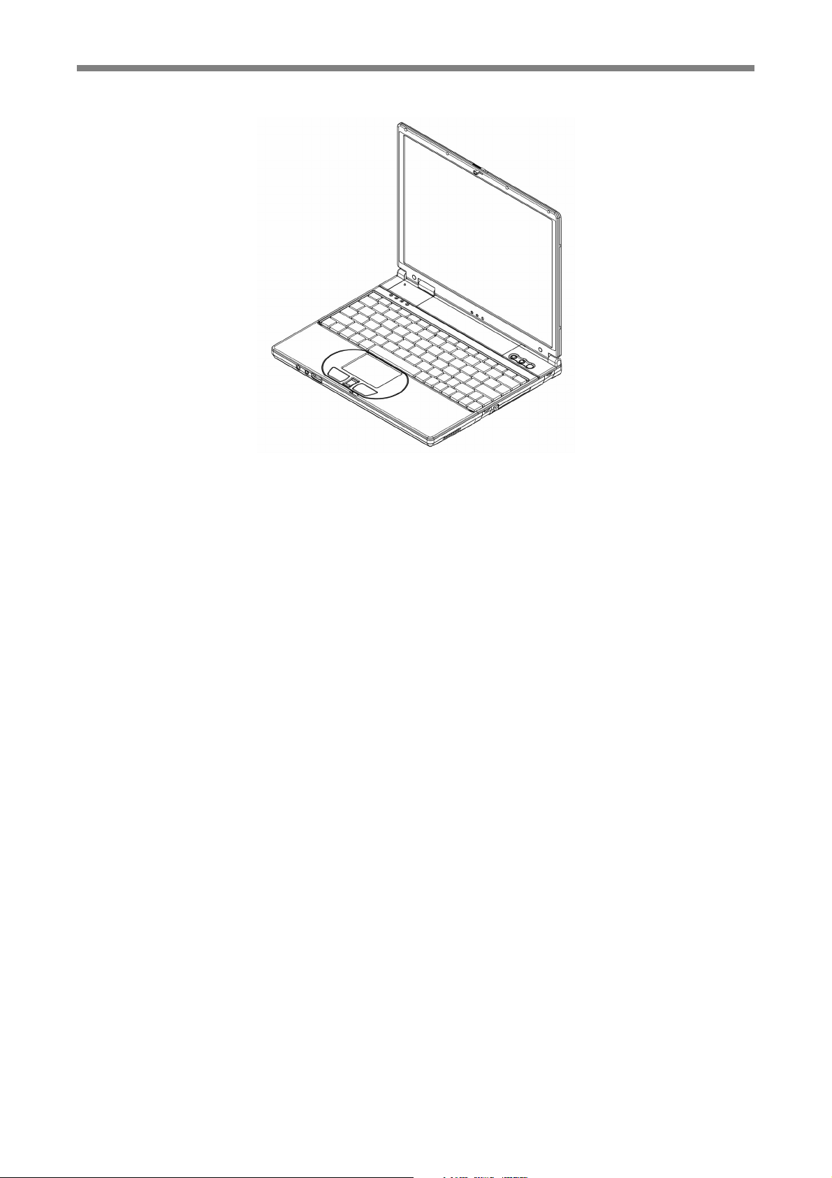
Prestigio Visconte 121
Notebook
Service Technical
Manual
Page 3

Prestigio Visconte 121 Technical Service Manual
This page is l ef t blank intentio nally.
Page 4

Prestigio Visconte 121 Technical Service Manual
CONTENTS
Chapter 1 Introduction ______________________________________________________ 1-1
1.1 Overview Of This Manual__________________________________________________________ 1-1
1.2 System Overview ________________________________________________________________ 1-1
1.3 Other References____________________________________________1-Error! Bookmark not defined.
Chapter 2 The BIOS Setup ___________________________________________________ 2-1
2.1 Configuration Software____________________________________________________________ 2-1
2.2 Running the Setup Utility __________________________________________________________ 2-2
2.3 Main Setup _____________________________________________________________________ 2-3
2.4 Advanced Setup _________________________________________________________________ 2-5
2.5 Security Setup___________________________________________________________________ 2-7
2.6 Boot Setup _____________________________________________________________________ 2-8
2.7 Exit Setup______________________________________________________________________ 2-9
Chapter 3 System Utilities____________________________________________________ 3-1
3.1 The BIOS Flash Utility ____________________________________________________________ 3-1
3.2 The KBC (H8) Flash Utility ________________________________________________________ 3-1
Chapter 4 Upgrading Memory ________________________________________________ 4-1
Chapter 5 Removing Mini-PCI Module __________________________________________ 5-1
Chapter 6 Preliminary Dis-Assembly ___________________________________________ 6-1
Chapter 7 Removing The HDD Drive ___________________________________________ 7-1
Chapter 8 Removing The Motherboard __________________________________________ 8-1
Chapter 9 Removing The Palmrest _____________________________________________ 9-1
Chapter 10 Removing The Modem Module _______________________________________ 10-1
Chapter 11 Removing The Heatsink ____________________________________________ 11-1
Chapter 12 Removing The LCD Display _________________________________________ 12-1
Chapter 13 Fuse Rating Table ________________________________________________ 13-1
I-I
Page 5

Prestigio Visconte 121 Technical Service Manual
This page is l ef t blank intentio nally.
I-II
Page 6
Prestigio Visconte 121 Technical Service Manual
Chapter 1 Introduction
1.1 Overview Of This Manual
This Service Manual is written for engineers and technicians and is meant to help them to
service and repair the notebook. Detail descriptions on major parts and components will
not be discussed in this manual. This manual is mainly written with Office 2000 Word
software. Should you find any error or spelling mistake that we have inadvertently missed,
we apologize for such negligence; but please let us know.
1.2 System Overview
VIA C3 Ezra-T EBGA 800MHz/933MHz/1GHz processor with 128KB (L1)/64KB
(L2) cache memory.
Core Logic: VIA chipset composing of VT8606-T Twister (NorthBridge) and
VIA VT82C686B (SouthBridge).
One SDRAM S.O. DIMM memory socket is upgradeable from the basic 128MB/256MB
to 640MB/768MB memory.
512KB Flash ROM contains BIOS and is easily user upgradeable.
System Display
UMA Module wi th embedded high performance 8MB/16MB/32MB video memory.
Display Panel: TFT 12.1” XGA.
System Storage
Industry standard 20GB/40GB 9.5mm hard disk drive.
Optional external USB industry standard 3.5inch 1.44MB floppy disk drive.
Optional external USB CD-ROM Drive, or
DVD-ROM drive, or
Combo Drive.
1-1
Page 7
Prestigio Visconte 121 Technical Service Manual
System Keyboard
83 full keys, including 2 Windows keys, and embedded numerical keypad.
Connectivity and Expansion
One 15-pin VGA port.
One microphone-in connector.
One headphone-out.
One RJ11 Fax/Modem connector.
Two 4-pin USB ports.
One DC-in Jack.
One RJ45 LAN connector.
One type II CF card connection.
One IEEE1394 port.
One type II slot for PCMCIA connection.
Power
Two battery sl ots to support dual Lithium Ion (Li -Ion) battery packs.
Offline battery charging time is around 2.5 hours for Li-Ion battery pack.
Full range 110 to 240V auto-switch AC adapter; 100Vac input voltage on load power
consumption < or = 1W.
Physical
Weight (TFT color, 12.1”) : 1.33kg, including one battery pack.
Length/Width/Height : 265mm/220mm/23mm.
Note: Weight and height might change due to different configurations and models.
Environment
Operating Temperature : 10°C to 35°C.
Non-Operating Tem perature : -20°C to 60°C.
Humidity : 20% to 80% non-condensing.
Shock : 5G operating, 60G non-operating.
Vibration : 3-200Hz @ 1.0G operating.
: 3-200Hz @ 1.5G non-operating.
Warning: Don't expose your notebook to excessive heat or coldness (frost). Don't
drop, spill fluids or open the exterior of the case. This can damage the
notebook and void the warranty.
1-2
Page 8

Prestigio Visconte 121 Technical Service Manual
POWER MANAGEMENT
Advanced Configuration Power Interface (ACPI) 2.0 for Windows XP®.
OPERATING SYSTEM
Windows® XP.
OPTIONS
Standard SDRAM S.O. DIMM self-fresh 512MB memory module for expansion from
128MB/256MB to 640MB/768MB.
Optional Lithium Ion (Li-Ion) battery pack in slot B.
External CD-ROM Drive, or
DVD-ROM Drive, or
Combo Drive.
1-3
Page 9

Prestigio Visconte 121 Technical Service Manual
This page is l ef t blank intentio nally.
1-4
Page 10
Prestigio Visconte 121 Technical Service Manual
Chapter 2 The BIOS Setup
2.1 Configuration Software
The notebook can easil y be configured to suit your personal needs. The built-in SETUP
program allows you to setup various system parameters. The information is stored in a
battery-backed CMOS memory; so when the power is turned off, your setup is retained.
This Configuration Software is sometimes referred to as CMOS Setup, BIOS Setup, or
simply the SETUP.
Note: The SETUP can be activated by pressing <F2> during system boot-up.
You are requested to perform the following one-time procedure immediately after you have
upgraded/reprogrammed your BIOS:
• Press <F2> during system boot-up to get into the SETUP.
• Go to the EXIT sub-menu and choose Load Setup Defaults. Press Enter.
• Now, you can customize the BIOS for your personal needs.
For detail on the BIOS SETUP, read on.
Note: For information on the BIOS upgrade, contact your local notebook dealer.
2-1
Page 11
Prestigio Visconte 121 Technical Service Manual
2.2 Running the Setup Utility
There are five major sub-menus in the SETUP program: Main Setup, Advanced Setup,
Security Setup, Boot Setup, and Exit Setup. Details on the five major sub-menus are
described on the following pages.
Movement within the SETUP utility
To move between the different item fields, use the cursor keys ↑ and ↓. To move between
the five SETUP sub-menus, use the cursor keys ← and →. To change the value of a field,
press the <+> and <−> keys. When you select one item, thi s item will be highlighted and a
brief explanation would be displayed in the Item Specific Help box located on the right
side of the screen. The followings are some of the most commonly used keys:
• Press <F1> to enter the menu of Help.
• Press <F9> to enter the menu of Setup Defaults, then press Enter to continue or
press Esc to abort.
• Press <F10> to enter the menu of Save & Exit. This would save modifications you
have made. Then exit.
• Press Enter to execute command.
• Press Esc to get to the EXIT Setup sub-menu, or to the next higher-level sub-menu.
Note: The settings shown on the following sub-menu displays are factory default
settings.
The content of these sub-menu displays, described in the rest of this chapter, is
subject to change in the future.
2-2
Page 12

Prestigio Visconte 121 Technical Service Manual
2.3 Main Setup
You will be greeted by this screen when you enter the Main Setup menu:
Main
Advanced Security Boot Exit
PhoenixBIOS Setup Utility
System Time:
System Date:
Internal HDD
System Memory:
Extended Memory:
CPU Type
CPU Speed
BIOS Version
KBC Version
F1
Help
Esc
Exit
Select Item
Select Menu
[15:54:23]
[11/12/2002]
[20004MB]
640 KB
121856 KB
VIA C3 Processor
800 MHz
A01
P00
−/+
Change Values
Enter
Select Sub-
Menu
<Tab>,<Shift-Tab>, or <Enter>
selects field.
F9
F10
Item Specific Help
Setup Defaults
Save and Exit
System Time:
Current time. Use <Tab>, <Shift-Tab>, or <Enter> keys to move around these fields. To
change the value, press <+> or <−> key.
System Date:
Today’s date. Use <Tab>, <Shift-Tab>, or <Enter> keys to move around these fi elds. To
change the value, press <+> or <−> key. Set any date from year 1901 to 2099. It will
automatically keep track of leap years. The system date can also be set from the operati n g
system.
Internal HDD:
Press [Enter] to enter the sub-menu. In the sub-menu, there are four options for HDD
type: Auto, User, CD/DVD, None. In general, you should choose the default value “Auto”
to let the system automatically detect the HDD you have in the system. If Auto fails to
recognize your HDD, you can choose value “User”; then enter the parameters according
to the specifications of your HDD.
2-3
Page 13

Prestigio Visconte 121 Technical Service Manual
System Memory:
This is for display only. T his shows the system memory is 640KB.
Extended Memory:
This is for display only. This shows the extended memory is 121856.
CPU Type:
This is for display only. This shows the type of CPU you have in your system.
CPU Speed:
This is for display only. This shows the processor speed is 800MHz.
BIOS Version:
This is for display only. This shows the BIOS version is A01.
KBC Version:
This is for display only. This shows the KBC version is P00.
2-4
Page 14
Prestigio Visconte 121 Technical Service Manual
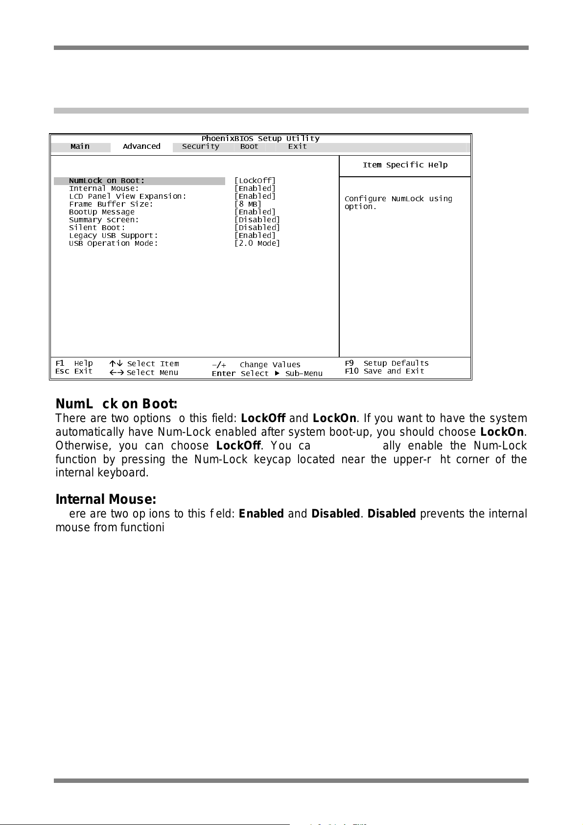
2.4 Advanced Setup
You will be greeted by this screen when you enter the Advanced Setup menu:
Main Advanced
PhoenixBIOS Setup Utility
Security Boot Exit
NumLock on Boot:
Internal Mouse:
LCD Panel View Expansion:
Frame Buffer Size:
BootUp Message
Summary screen:
Silent Boot:
Legacy USB Support:
USB Operation Mode:
F1
Esc
Help
Exit
Select Item
Select Menu
[LockOff]
[Enabled]
[Enabled]
[8 MB]
[Enabled]
[Disabled]
[Disabled]
[Enabled]
[2.0 Mode]
−/+
Change Values
Enter
Select Sub-Menu
Item Specific Help
Configure NumLock using
option.
F9
Setup Defaults
F10
Save and Exit
NumLoc k on B o ot:
There are two options to this fi eld: LockOff and LockOn. If you want to have the system
automatically have Num-Lock enabled after system boot-up, you should choose LockOn.
Otherwise, you can choose LockOff. You can also manually enable the Num-Lock
function by pressing the Num-Lock keycap located near the upper-right corner of the
internal keyboard.
Internal Mouse:
There are two options to this field: Enabled and Disabled. Disabled prevents the internal
mouse from functioning, but frees up IRQ12.
LCD Panel View Expansion:
There are two options to this field: Enabled, and Disabled. Enabled allows the panel view
to be expanded; such expansion may have an adverse effect on the quality of displ ayed
graphic/text. Disabled, in some video mode, may reduce the panel view.
Frame Buffer Size:
There are three options for video memory: 8MB, 16MB, and 32MB. User can select which
memory size to be used according to the requirement.
BootUp Message:
There are two options to this field: Enabled, and Disabled. Disabled prevents displ aying
of the logo screen. Refer to Silent Boot below.
2-5
Page 15

Prestigio Visconte 121 Technical Service Manual
Summary sc reen:
There are two options to this fi eld: Disabled, and Enabled. This field allows you to enable
or to disable the display of system configuration during system boot-up.
Silent Boot:
There are three options to this field: Enabled, Disabled, and Black.
• Enabled allows the system to display the logo screen during system boot-up.
• Disabled does not allow showing the logo screen during system boot-up. As a result,
the POST (Power On Self Test) screen would be displayed.
• Otherwise, a screen would be displayed. This <Black> screen woul d last for about 20
seconds, and would appear as if the system has no response.
Legacy USB Support:
There are two options to this field: Disabled, and Enabled. Enabled allows the system to
boot up from USB floppy.
USB Operation Mode:
There are two options to this field: 1.1 Mode, and 2.0 Mode. The default value is 2.0
Mode.
2-6
Page 16
Prestigio Visconte 121 Technical Service Manual
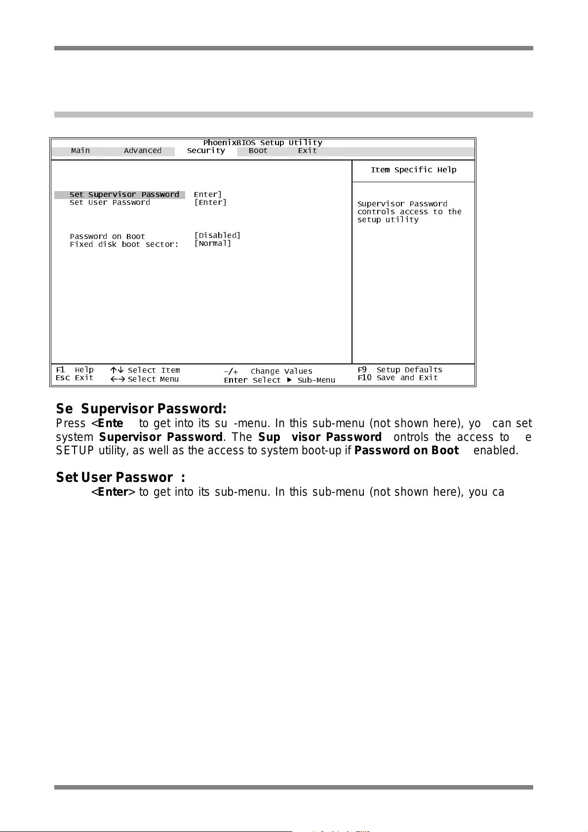
2.5 Security Setup
You will be greeted by this screen when you enter the Security Setup menu:
Main Advanced
PhoenixBIOS Setup Utility
Security
Boot Exit
Set Supervisor Password
Set User Password
Password on Boot
Fixed disk boot sector:
F1
Help
Esc
Exit
Select Item
Select Menu
Enter]
[Enter]
[Disabled]
[Normal]
−/+
Enter
Change Values
Select Sub-Menu
Item Specific Help
Supervisor Password
controls access to the
setup utility
F9
Setup Defaults
F10
Save and Exit
Set Supervisor Password:
Press <Enter> to get into its sub-menu. In this sub-menu (not shown here), you can set
system Supervisor Password. The Supervisor Password controls the access to the
SETUP utility, as well as the access to system boot-up if Password on Boot is enabled.
Set User Password:
Press <Enter> to get into its sub-menu. In this sub-menu (not shown here), you can set
system User Password. The User Password controls the access to system boot-up if
Password on Boot is e nab led.
Password on Boot:
The setting of this field is available only if the Supervisor Password, and/or the User
Password had been set. There are two options to this field: Enabled, and Disabled. If
enabled, you can use the Supervisor Password (or use the User Password, if User
Password had i ndeed been set) to access system during system boot-up.
Fixe d disk boot sector:
There are two options to this field: Write Protect and Normal. If Write Protect, the HDD
will automatically prevent and protect against virus intrusi on during boot-up.
2-7
Page 17
Prestigio Visconte 121 Technical Service Manual
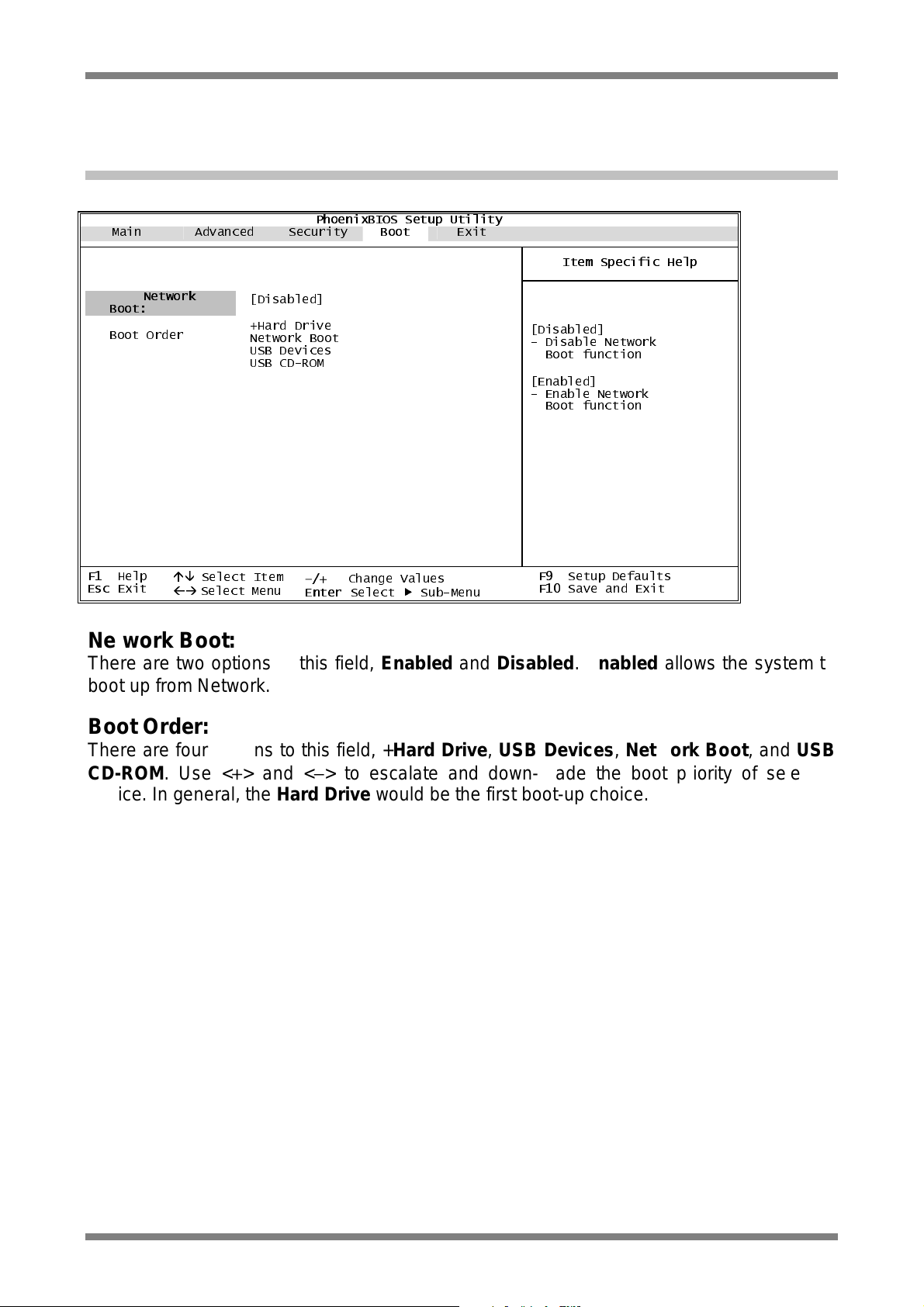
2.6 Boot Setup
You will be greeted by this screen when you enter the Boot Setup Menu:
Main Advanced Security
PhoenixBIOS Setup Utility
Boot
Exit
Boot Order
F1
Esc
Boot:
Help
Exit
Network
Select Item
Select Menu
[Disabled]
+Hard Drive
Network Boot
USB Devices
USB CD-ROM
−/+
Enter
Change Values
Select Sub-Menu
Item Specific Help
[Disabled]
- Disable Network
Boot function
[Enabled]
- Enable Network
Boot function
F9
Setup Defaults
F10
Save and Exit
Network Boot:
There are two options to this field, Enabled and Disabled. Enabled allows the system to
boot up from Network.
Boot Order:
There are four opti ons to this field, +Hard Drive, USB Devices , Network Boot, and USB
CD-ROM. Use <+> and <−> to escalate and down-grade the boot priority of selected
device. In general, the Hard Drive would be the first boot-up choice.
2-8
Page 18

Prestigio Visconte 121 Technical Service Manual
2.7 Exit Setup
You will be greeted by this screen when you enter the Exit Setup Menu:
Main Advanced Security Boot
PhoenixBIOS Setup Utility
Exit
Exit Saving Changes
Exit Discarding
Changes
Load Setup Defaults
Discard Changes
Save Changes
F1
Help
Esc
Exit
Select Item
Select Menu
−/+
Change Values
Enter Select Sub-Menu
Item Specific Help
Exit System Setup and save
your changes to CMOS.
F9
Setup Defaults
F10
Save and Exit
Exit Saving Changes:
Save the changes that you have just made, and then exit the SETUP.
Exit Discarding Changes:
If you don’t want to save the changes you have just made, choose this item to reject all the
changes and exit the SETUP.
Load Setup Defaults:
If you are not sure how to setup certain fields, choose this item. The syste m would get the
default settings for you.
Discard Changes:
If you don’t want to keep the changes you have just made, choose this item. The syste m
would load the previously saved values for you.
Save Chan ge s:
Save the changes you have just made.
2-9
Page 19

Prestigio Visconte 121 Technical Service Manual
This page is l ef t blank intentio nally.
2-10
Page 20

Prestigio Visconte 121 Technical Service Manual
Chapter 3 System Utilities
3.1 The BIOS Flash Utility
You would get the BIOS flash utility (Phlash.exe), and the latest <rom-file> from PMDIST.
The format for the <rom-file> name is 300Adddd.rom; where “dddd” is a 4-digit running
number.
The following is the procedure for flashing BIOS:
• Boot up to Native MS-DOS mode. Make sure emm386.exe and himem.sys are not
loaded into the system memory.
• Enter the following DOS command from the CD-ROM drive:
Phlash /c <rom-file>
• The flashing will be completed when the system restarts after hitting any key.
Note: The flash utility program will issue a warning message, if the ROM file and the
system’s motherboard do not match with one another.
3.2 The KBC (H8) Flash Utility
You would get the KBC flash utility (H8fb.exe), and the latest <kbc-file> from PMDIST.
The format for the <kbc-file> name is CP10V-P00-.bin; where “00” is a 2-digit running
number.
The following is the procedure for flashing BIOS:
• Boot up to Native MS-DOS mode. Make sure emm386.exe and himem.sys are not
loaded into the system memory.
• Enter the following DOS command from the CD-ROM drive:
H8fb <kbc-file>
• The flashing will be completed when the system shutdown automatically.
3-1
Page 21

Prestigio Visconte 121 Technical Service Manual
This page is l ef t blank intentio nally.
3-2
Page 22

Prestigio Visconte 121 Technical Service Manual
Groove
Chapter 4 Upgrading Memory
Your notebook is equipped with a highly configurable memory sub-unit. The industry
standard SDRAM S.O.DIMM memory module is available for memory upgrade from
128MB/256MB up to 640MB/768MB. There is one memory socket, located on the bottom
side of the system unit. The table below illustrates all the possible ways system me mory
can be configured.
Total Memory On-Board Memory
128MB 0MB
128MB 128MB
256MB 128MB
256MB 0MB
256MB 256MB
384MB 256MB
384MB 128MB
512MB 256MB
512MB 0MB
512MB 512MB
640MB 128MB
640MB 512MB
768MB 256MB
768MB 512MB
orientation of modul e
for indicating the
SODIMM Memor y
128MB
0MB
128MB
256MB
0MB
128MB
256MB
256MB
512MB
0MB
512MB
128MB
512MB
256MB
1.25” ma x
SDRAM S.O. DIMM Memory Module
4-1
Page 23

Prestigio Visconte 121 Technical Service Manual
Legend 4-1:
• Make sure the system is properly shutdown.
• Remove the screw as shown #1.
• Lift up the compartment door as shown by #2.
4-2
Page 24

Prestigio Visconte 121 Technical Service Manual
The Groove
Legend 4-2:
• Press the spring locks sideways as shown by #1.
• The memory module would pop up as shown by #2.
4-3
Page 25

Prestigio Visconte 121 Technical Service Manual
The Groove
Legend 4-3:
• Remove the memory module as shown.
To restore th e s ystem ba ck t o its as sem b le d situation:
• Reverse the steps in Legend 4-1 to Legend 4-3 in this chapter.
4-4
Page 26

Prestigio Visconte 121 Technical Service Manual
Chapter 5 Removing Mini-PCI Module
Your notebook i s equipped with a Mini-PCI Module. The Mini-PCI supports both LAN and
modem connections. Below i s the procedure on how to remove Mini -PCI Module. Reverse
the procedure to assemble a Mini-PCI Module.
Legend 5-1:
• Make sure the system is properly shutdown.
• Flip the system upside down (not shown).
• Remove the screw as shown by #1.
• Remove the compartment door as shown by #2.
5-1
Page 27

Prestigio Visconte 121 Technical Service Manual
The Groove
Legend 5-2:
• Press the spring locks sideways as shown by #1.
• The Mini-PCI module would pop up as shown by #2.
5-2
Page 28

Prestigio Visconte 121 Technical Service Manual
The Groove
Legend 5-3:
• Remove the Mini-PCI module as shown.
To restore th e s ystem ba ck t o its as sem b le d situation:
• Reverse the steps in Legend 5-1 to Legend 5-3 in this chapter.
5-3
Page 29

Prestigio Visconte 121 Technical Service Manual
This page is l ef t blank intentio nally.
5-4
Page 30

Prestigio Visconte 121 Technical Service Manual
Chapter 6 Preliminary Dis-assembly
The following is the preliminary procedure for preliminary dis-assembly.
Legend 6-1:
• Make sure the system is properly shutdown.
• Flip the system upside down (not shown).
• Push the two battery latches inward as shown by arrows simultaneously.
6-1
Page 31

Prestigio Visconte 121 Technical Service Manual
Slot A Battery Pack
Battery Pack Connector
Legend 6-2:
• Pull the battery pack out as shown.
6-2
Page 32

Prestigio Visconte 121 Technical Service Manual
Legend 6-3:
• Remove the six screws as shown.
6-3
Page 33

Prestigio Visconte 121 Technical Service Manual
Legend 6-4:
• Flip the display panel as shown.
6-4
Page 34

Prestigio Visconte 121 Technical Service Manual
Legend 6-5:
• Disconnect the palmrest cable as shown by #1.
• Remove the palmrest as shown by #2.
6-5
Page 35

Prestigio Visconte 121 Technical Service Manual
This page is l ef t blank intentio nally.
6-6
Page 36

Prestigio Visconte 121 Technical Service Manual
Chapter 7 Removing The HDD Drive
Follow the steps as described in Legend 6-1 to Legend 6-5 of Chapter 6, then proceed
from Legend 7-1 in this chapter. Reverse the procedure to assemble the HDD drive.
Legend 7-1:
• Remove the two screws as shown by #1.
• Di sconnect the HDD drive cable as shown by #2.
• Remove the HDD drive as shown by #3.
7-1
Page 37

Prestigio Visconte 121 Technical Service Manual
Legend 7-2:
• Remove the four screws as shown by #1.
• Remove the HDD drive cable and the bracket as shown by #2.
To restore th e s ystem ba ck t o its as sem b le d situation:
• Reverse the steps in Legend 7-1 to Legend 7-2 of this chapter.
• Reverse the steps in Legend 6-1 to Legend 6-5 of Chapter 6.
7-2
Page 38

Prestigio Visconte 121 Technical Service Manual
Chapter 8 Removing The Motherboard
Follow the procedures from Legend 6-1 to Legend 6-5 of Chapter 6, then proceed from
Legend 8-1 of this chapter. Reverse the procedure to assemble the Motherboard.
Legend 8-1:
• Disconnect the keyboard as shown by #1.
• Remove the keyboard as shown by #2.
• Remove the covers of left/right hinges as shown by #3.
8-1
Page 39

Prestigio Visconte 121 Technical Service Manual
Legend 8-2:
• Gently slide the FPC door cover to the right as shown.
8-2
Page 40

Prestigio Visconte 121 Technical Service Manual
Legend 8-3:
• Disconnect the FPC door cable as shown by #1.
• Remove the FPC door as shown by #2.
8-3
Page 41

Prestigio Visconte 121 Technical Service Manual
Legend 8-4:
• Disconnect the FPC cover as shown by #1.
• Remove the four screws as shown by #2.
8-4
Page 42

Prestigio Visconte 121 Technical Service Manual
Legend 8-5:
• Disconnect the display panel cable as shown by #1.
• Remove the display panel as shown by #2.
8-5
Page 43

Prestigio Visconte 121 Technical Service Manual
Legend 8-6:
• Remove the seven screws as shown by #1.
• Remove the uppercase as shown by #2.
8-6
Page 44

Prestigio Visconte 121 Technical Service Manual
The Ca ble
Legend 8-7:
• Remove the two screws as shown by #1.
• Remove the bracket as shown by #2.
• Remove the two screws as shown by #3.
• Disconnect the cable as shown by #4.
• Remove the HDD drive as shown by #5.
• Remove the bracket as by #6.
8-7
Page 45

Prestigio Visconte 121 Technical Service Manual
Legend 8-8:
• Remove the six screws as shown by #1.
• Disconnect the five cables as shown by #2.
• Disconnect the washer as shown by #3.
• Remove the motherboard as shown by #4.
To restore th e s ystem ba ck t o its as sem b le d situation:
• Reverse the steps in Legend 8-1 to Legend 8-8 of this chapter.
• Reverse the steps in Legend 6-1 to Legend 6-5 of Chapter 6.
8-8
Page 46

Prestigio Visconte 121 Technical Service Manual
Chapter 9 Removing The Palmrest
Follow the steps as described in Legend 6-1 to Legend 6-5 in Chapter 6. Reverse the
procedure to assemble the Palmrest.
To restore th e s ystem ba ck t o its as sem b le d situation:
• Reverse the steps in Legend 6-1 to Legend 6-5 of Chapter 6.
9-1
Page 47

Prestigio Visconte 121 Technical Service Manual
This page is l ef t blank intentio nally.
9-2
Page 48

Prestigio Visconte 121 Technical Service Manual
Chapter 10 Removing The Modem Module
Follow the steps as described in Legend 6-1 to Legend 6-5 of Chapter 6; then followed by
Legend 8-1 to Legend 8-8 of Chapter 8 before proceeding with the steps as below.
Legend 10-1:
• Remove the two screws as shown by #1.
• Remove the modem module as shown by #2.
• To restore the system ba ck t o its as sem b le d sit uat io n:
• Reverse the steps in Legend 10-1 of this chapter.
• Reverse the steps in Legend 8-1 to Legend 8-8 of Chapter 8.
• Reverse the steps in Legend 6-1 to 6-5 of Chapter 6.
10-1
Page 49

Prestigio Visconte 121 Technical Service Manual
This page is l ef t blank intentio nally.
10-2
Page 50

Prestigio Visconte 121 Technical Service Manual
Chapter 11 Removing The Heatsink
Follow the steps as described in Legend 6-1 to Legend 6-5 of Chapter 6; then followed by
Legend 8-1 to Legend 8-8 of Chapter 8 before proceeding with the steps as below.
Legend 11-1:
• Remove the four screws as shown by #1.
• Remove the heatsink as shown by #2.
To restore th e s ystem ba ck t o its as sem b le d situation:
• Reverse the steps in Legend 11-1 of this chapter.
• Reverse the steps in Legend 8-1 to Legend 8-8 of Chapter 8.
• Reverse the steps in Legend 6-1 to Legend 6-5 of Chapter 6.
11-1
Page 51

Prestigio Visconte 121 Technical Service Manual
This page is l ef t blank intentio nally.
11-2
Page 52

Prestigio Visconte 121 Technical Service Manual
Chapter 12 Removing The LCD Display
Below is the procedure on how to remove the LCD Display. Reverse the procedure to
assemble the LCD Display.
Legend 12-1:
• Make sure the system is properly shutdown.
• Remove the covers of the left/right hinges as shown.
12-1
Page 53

Prestigio Visconte 121 Technical Service Manual
Legend 12-2:
• Flip the display panel as shown by #1.
• Gently slide the LCD FPC door cover to the right as shown by #2.
12-2
Page 54

Prestigio Visconte 121 Technical Service Manual
Legend 12-3:
• Disconnect the LCD FPC door cable as shown by #1.
• Remove the LCD FPC door as shown by #2.
12-3
Page 55

Prestigio Visconte 121 Technical Service Manual
Legend 12-4:
• Remove the FPC cover as shown by #1.
• Remove the four screws as shown by #2.
12-4
Page 56

Prestigio Visconte 121 Technical Service Manual
Legend 12-5:
• Disconnect the LCD FPC cable as shown by #1.
• Remove the LCD display panel as shown by #2.
12-5
Page 57

Prestigio Visconte 121 Technical Service Manual
Legend 12-6:
• Remove the two rubber pads as shown by #1.
• Remove the two screws as shown by #2.
• Push the LCD latch as shown by #3.
12-6
Page 58

Prestigio Visconte 121 Technical Service Manual
Legend 12-7:
• Remove the front panel as shown.
12-7
Page 59

Prestigio Visconte 121 Technical Service Manual
Legend 12-8:
• Remove the screw as shown by #1.
• Disconnect the LCD cable as shown by #2.
• Disconnect the LCD FPC cable as shown by #3.
• Remove the inverter board as shown by #4.
12-8
Page 60

Prestigio Visconte 121 Technical Service Manual
Legend 12-9:
• Remove the four screws as shown.
12-9
Page 61

Prestigio Visconte 121 Technical Service Manual
Legend 12-10:
• Remove the rear display panel as shown by #1.
• Remove the four screws as shown by #2.
• Remove the two brackets as shown by #3.
• Disconnect and remove the cable as shown by #4.
To restore th e s ystem ba ck t o its as sem b le d situation:
• Reverse the steps in Legend 12-1 to Legend 12-10 of this chapter.
12-10
Page 62

Prestigio Visconte 121 Technical Service Manual
F1
F2
CHARGER
CHARGER
Chapter 13 Fuse Rating Table
Board
VGA
DC-IN
SO DIMM
MEMORY
USB
USB
Location
F505
F501
F502
F503
F504
Rating
1.1A/6V
5A/125V
2A/125V
1.6A/6V
1.6A/6V
5A/125V
5A/125V
13-1
Page 63

www.prestigio.com
 Loading...