

Page 1

PRESTIGIO VISCONTE 120
TECHNICAL SERVICE
MANUAL
Page 2
TECHNICAL SERVICE MANUALPrestigio Visconte120
2
Page 3

TECHNICAL SERVICE MANUAL Prestigio Visconte120
1.1. Hardware Specifications……………………………………………………
1.2. Software Specifications………..……………………………….…………...
223II0 Rev : A Page 2 - 27
3
Page 4

TECHNICAL SERVICE MANUALPrestigio Visconte120
1. Overview
Intel Centrino platform notebook with Intel Banias/Dothan CPU up to 2.0GHz, 2.5 inch
HDD, Multimedia, LAN, Modem, IEEE1394, USB2.0, SPDIF and PCMCIA. The fellow is a
summary of major components:
Main Chip:
CPU Intel 0.13u/ 0.09u Banias/Dothan Processor 1.4GHz-2.0GHz CPU (478P M-FCPGA) with
1MB/2MB L2 Cache
CPU Core Power Maxim 1907A
System 3V/5V Power Semtech SC1404
Core Logic: Intel 855GME Chipset
Memory SO-DIMM 200pin DDR333 128MB/256MB/512MB/1GB DDR DRAM support
Clock Generator ICS950813
Graphic Engine Intel 855GME Build-in
Card Bus TI PCI1410 Single Slot, 32bit Cardbus Controller
Sound Codec :VIA Vt1612A (AC’ 97 Audio Codec Component Specification Rev.2.1with S/PDIF).
Audio Amp.: TI TPA6011A4 for L/R Channel Audio (1Watt x 2)
IEEE1394 Ti TSB43AB22A(OHCI-1.1)
Keyboard Controller ITE 8510E
LAN MAC + PHY: RealTek RTL8100CL Single Chip Solution
Display Chrontel CH7011A for TV Display
BIOS 4Mbit
Storage Devices:
3.5” 25.4mm High Hard Disk Drive
ATA 100 Spec Support
CD/DVD ROM CD-RW/DVD Combo and Dual DVD (Options)
USB External USB Storage device.
Legacy Support
Multimedia:
Sound
223II0 Rev : A Page 3 - 27
Non-Directional Condenser Microphone
• Model No.: EM-123Y
• Sensitivity: -43 +/- 3db
• Impedance: 2K ohm
• Operation Temperature: -10
Two Build-in Dynamic Loud Speaker
1.5 watt x 8 ohm x 2 (Speaker) (4:3)
Two Optional Dynamic Loud Speaker
1 watt x 8 ohm x 2 (Speaker) (16:10)
4
o
C ~+60oC
Page 5
TECHNICAL SERVICE MANUAL Prestigio Visconte120
Two Audio Jacks Support ( Line Out x1, Microphone In x1)
Volume Control by Function key
Line Out Jack with S/PDIF support
Communication / IO port:
RJ11 Standard AC97 MDC interface with Scatter, Gather and Burst capability
Wake on Ring on APM or ACPI mode through AC97 link
RJ45
USB2.0 One USB2.0 connectors support.
IEEE1394 One IEEE 1394 Connector support
PCMCIA One Type II PCMCIA Slot
LAN On board
CRT Standard15Pin D-Sub Type CRT Connector
S-Video NTSC/PAL Compliant S-Video Output
Power:
AC Adapter
Battery module
65W (20V)
Smart battery with Dummy Charger architecture
Battery : 3S2P/4S1P with 2200/2000 mAH Li-ion Cell Battery
Compliance:
PCI 2.2
PC99 compliant
ACPI compliant
223II0 Rev : A Page 4 - 27
5
Page 6

TECHNICAL SERVICE MANUALPrestigio Visconte120
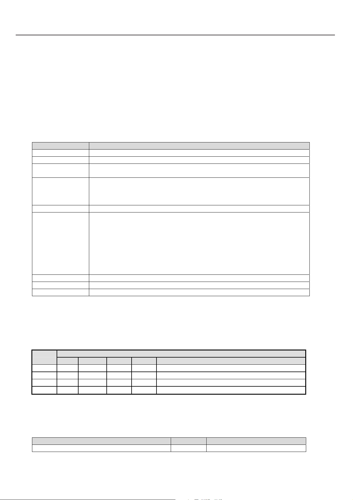
1.1 Functions Specification
1.1.1 Device Specification
Category Specification Note
CPU
Core Logic
Vendor: INTEL
Banias (.13u) Dothan (.09u) Processor 478pin 478P M-FCPGA Package
• Processor core/bus speeds: 1.4GHz-2.0GHz.
• On die L2 cache – 1M/2M Bytes
• Fully compatible with previous Intel microprocessors
− Support for MMX technology
− Support for Streaming SIMD Extensions 2 (SSE2)
• Power Management Features Intel Enhanced Intel SpeedStep technology
• FSB: 400MHz
Vendor: INTEL
North Bridge: 855GME, South Bridge: ICH4-M
• PCI to Host Bridge
− Support Intel Processor FSB at 400MHz
− AGTL+ Bus Driver Technology
• DRAM Controller
− Support 4 bank of 2.5V DDR SDRAM
− DDR 333 support (64-bit without ECC)
• PCI I/F (PCI 2.2 Compliant)
• Integrated Graphic Support
• No External AGP Bus Support
• Integrate IDE controller
− HDD support “ Ultra DMA/33, 66, 100
− CDROM support “ Ultra DMA/33
• System Peripheral Support
− DMA Controller:
Two 8237A controller
8/16 bit DMA data transfer
Distributed DMA Support
− Interrupt Controller:
Two 8259A Compatible interrupt controllers
Level or edge triggered programmable
Serial Interrupt
− System Timer based on 8254 compatible programmable 16bit counters
223II0 Rev : A Page 5 - 27
6
Page 7

TECHNICAL SERVICE MANUAL Prestigio Visconte120
− Real Time Clock with 256 Bytes Battery-backed RAM
− LPC-bus support for keyboard controller and super I/O
• USB controller 6 Ports
• AC’ 97 Audio and modem CODEC Interface Support
• SMBus controller
• System Power Management
• Integrated 10/100MB LAN MAC
System Memory Two Slot Standard 200-pin DDR SO-DIMM support
• Size: 128/256/512/1024 MB
• Type: DDR S DRAM 2.5V
• Frequency: PC2700 ( DDR333)
• CL=2/2.5
• Operating ambient temperature: 0
• SPD Function Support
IEEE1394
Clock Generator ICS950813
BIOS ROM 4Mb Flash EEPROM
VGA Controller Integrated Graphics
USB2.0 ICH4-M built in
Card Bus TI PCI1410
Sound VIA Vt1612A
223II0 Rev : A Page 6 - 27
• T1 TSB43AB22A (OHCI-1.1 support)
•
Vendor: ICS
•
Generate System clock for CPU, DDR, PCI, USB and 14.318MHz.
•
Provide Spread Spectrum function
• Vendor: AMIC
• Including system and VGA BIOS
• Support shadow system BIOS
• Support shadow VGA BIOS
• Core Frequency of 250 MHz
• 3D Setup and Render Engine
• High Quality Texture Engine
• 3D Graphics Rasterization Enhancements
• 2D Graphics
• Video Overlay
• Compliant with Universal Serial Bus Specification Revision 2.0
• Compliant with Enhanced Host Controller Interface Specification Revision 0.95
• Compliant with Universal Host Controller Interface Specification Revision 1.1
• PCI multi-function device consists of two UHCI Host Controllers for
full/low-speed signaling and one EHCI Host Controller core for high-speed signaling
• 4 downstream facing ports in the root hub with integrated physical layer
transceivers shared by UHCI and EHCI Host Controllers
• Supports PCI-Bus Power Management Interface Specification release 1.1
• Legacy support for all downstream facing ports
• Vendor: TI
• PCI master device
• PC/Card Bus Ty pe II X1 (Don’t support Type III device)
• Supports 3.3V/ 5V PC Card 16 cards and 3.3V Cardbus Card
• Vendor: VIA
• AC-97 codec
• Wavetable synthesizer support
• Integrate AC’ 97 Audio Codec 18bits (AC’97 2.1 compliance)
o
C ~ 70oC
7
Page 8

• Sound Blaster compatibility.
• SPDIF out
• Operating ambient temperature: 0
Audio Amplifier 1: LM4835
•
Vendor: NS
•
Provide Bridge-Tied Load or Single End ed Modes
KB Controller ITE 8510E
• Vendor: ITE
• Internal KB controller
• Support PS/2 devices( Touch Pad)
• Support GPIO functions
• Two SMBus controller
• CPU temperature senser
• DAC support ( battery charge control )
• ADC support ( Inverter brightness control )
• X-BUS support ( BIOS )
• FAN speed control
LAN REALTEK RTL8100CL built-in Mac & PHY
• Plug & Play compatible
• 32bit PCI BUS master with DMA controller for low CPU and BUS utilization
• IEEE802.3 & 802.3u standard compatible
• Single 25MHz clock for 10 & 100 Mbps operation
o
C ~ 85oC
TECHNICAL SERVICE MANUALPrestigio Visconte120
223II0 Rev : A Page 7 - 27
8
Page 9

TECHNICAL SERVICE MANUAL Prestigio Visconte120
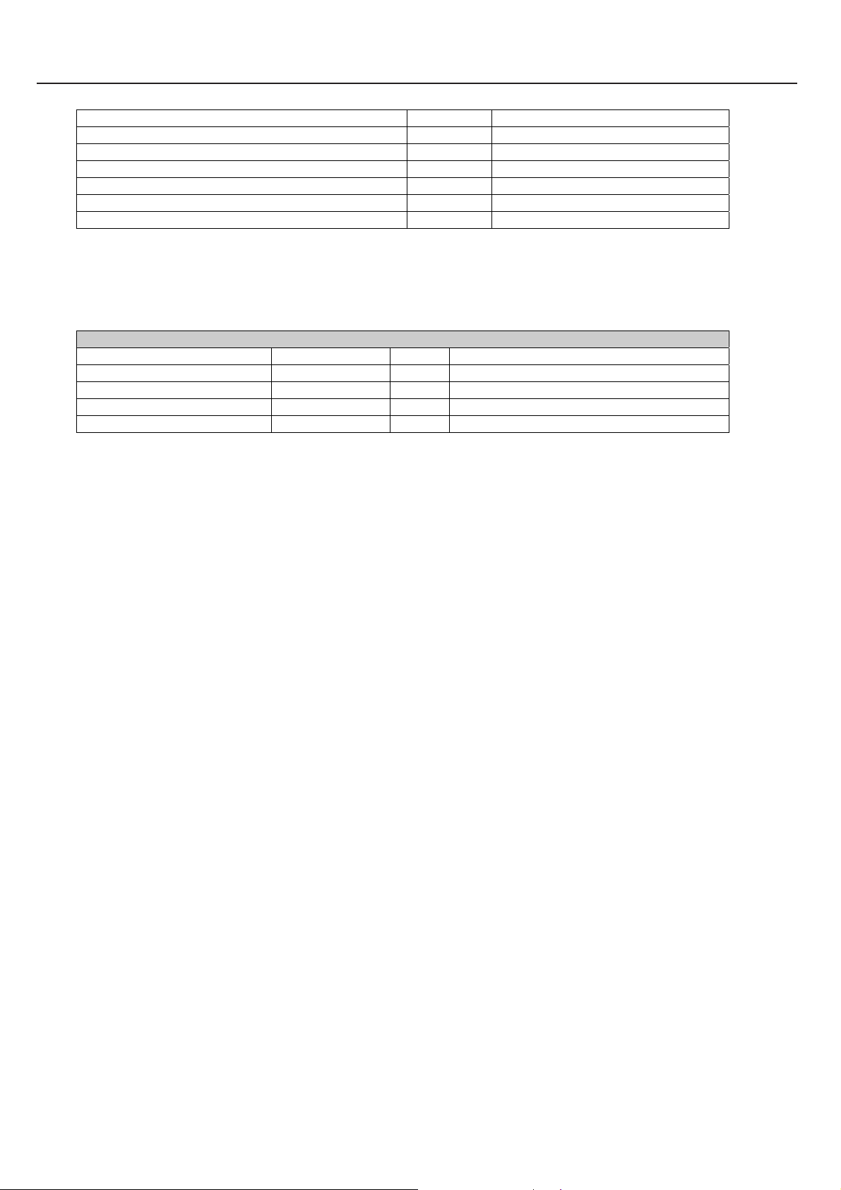
1.2 I/O Port
Category Specification Note
CRT Port
S-Video Port
IEEE1394
USB
Line Out
Mic In
Modem
LAN
Card Bus Slot
Point Device
INT/KB
1 Port (Standard D-Sub 9 Pin connector)
1 S-Video port support
1 Port (OHCI-1.1 support)
1 Port: Base connector, 1.1/2.0 Compliant
1 Jacks (Stereo Mini Pin Jack with S/PDIF)
1 Jack (Mono Mini Pin Jack)
1 Port (RJ-11)
1 Port (RJ-45)
Type II X 1 Supports 3.3V/ 5V PC Card 16 cards and 3.3V Cardbus Card
Internal Touch Pad – PS/2 mouse I/F
• Vendor: Synaptics
• Model:
• 2 buttons support Right/Left
Sumrex/ Chicony
•
223II0 Rev : A Page 8 - 27
9
Page 10
1.3 Power Supply
Battery
AC Adapter
RTC Battery
DC/DC
Converter
Battery Pack general spec.
•
• Operating ambient temperature: 0
• Charge temperature: 0
• Self discharge rate: Fully charged battery will be at least 80% of full charge
•
• Pack Vendor: ?
• Capacity: 2200/2000mAH Li-ion battery
• Cell Vendor: 4S1P-> ?
• Size: 18650
• Pack Configure: 4S1P / 3S2P
• Pack Capacity: 4S1P-> 2200mAH, 14.8V, 32.56W
Charge Strategy
Dummy Charger Battery architecture
•
•
•
Battery voltage up to 16.8V .(SMBUS)
Battery temperature over 50 degree C (SMBUS)
Charging time over 6 hrs
Vendor :Li-Shin, Liteon, Hipro
Input: AC 100~ 240V, 50/60Hz
Output: 20V, 3.25A, 65W
Real-time clock/calendar with a coin type battery back up ( rechargeable )
Vendor: MAXELL-ML1220
Voltage: 3V
Capacity: 14mAh
RTC Power Plane Power Consumption: 5uA / 3V
Estimated R TC Battery Life: 2 years
Output Tolerance Max load Test spec
5.0V +/- 5% 4.5A 5.5A
3.3V +/- 5% 4.5A 5.5A
12V +/- 5% 0.2A 0.2A
2.5V +/- 5% 4.5A 5.0A
1.35V +/- 3% 2.0A 2.0A
1.25V +/- 3% 1.5A 1.5A
Gas Gauge: BQ2060
o
C ~ 60oC
when stored at 25
Protection: Over charge protection
Over and under voltage protection
Over current protection
Thermal protection
3S2P-> ?
3S2P-> 2000/2200mAH, 10.8/11.1V, 43.2/48.8W
Charger: ITE8510E
Charge Current: System off Max. 2.0A.
System on Max. 0.7A
Charging terminate: Charging current lower than 200mA
o
C ~ 60oC
o
C, 85% RH for a period of one month
TECHNICAL SERVICE MANUALPrestigio Visconte120
223II0 Rev : A Page 9 - 27
10
Page 11

TECHNICAL SERVICE MANUAL Prestigio Visconte120
1.4 Power-On Source
No
Note
System Power Button *System power on control
1.
*Push this button 4 sec will happen H/W power shut down
This item works both when system is at on and off state
Besides RTC and AUX power plane, all power plane will turn
off until the releasing of the power button
1.5 Power Plane
Name Level System off System on Standby STD W/O AC & BAT
No
VCC3_AUX 3.3V
1.
VCC5_AUX 5V
2.
12V_AUX 12V
3.
VCC3_SUS 3.3V OFF
4.
VCC3 3.3V OFF
5.
VCC5 5V OFF
6.
VCC2.5 2.5V
7.
VCC1.35 1.35V
8.
VCC1.25 1.25V
9.
12V 12V OFF
10.
RTCVCC 2.0~3.3V
11.
VCCP 1.05V
12.
VCC_CORE 1.484V
13.
ON ON ON ON OFF
ON ON ON ON OFF
ON ON ON ON OFF
ON ON OFF OFF
ON ON OFF OFF
ON ON OFF OFF
OFF ON ON OFF OFF
OFF ON ON OFF OFF
OFF ON ON OFF OFF
ON ON OFF OFF
ON ON ON ON ON
OFF ON OFF OFF OFF
OFF ON OFF OFF OFF
1.6 Connector
Connector Location Pin No
No
HDD Data CON CON24
1.
CDROM CON CON16
2.
SUB BAT CON BT1
3.
Bluetooth Dongle CON CON23
4.
Cardreader FFC CON CON10
5
S-Video CON CON14
6
DC_IN JACK CON11
7
CRT FFC CON CON5
8.
LAN/MODEM JACK CON12
9.
1394 CON CON21
10.
MIC JACK CON20
11.
LINE OUT JACK CON19
12.
MDC CON CON25
13.
MODEM CON CON28
14
USB CON CON6
15.
LCD CON CON2
16.
INVERTER CON CON1
17
DDR SO-DIMM CON17,CON18
18.
PCMCIA SOCKET CON9
19.
Battery CON CON15
20.
44
50
2
4
10
4
5
10
10
4
5
8
30
2
4
16
12
200
68
10
223II0 Rev : A Page 10 - 27
11
Page 12
INT K/B CON CON4
21.
TOUCHPAD CON CON26
22.
MINI PCI CON CON27
23.
LED FPC CON CON7
24.
CPU FAN CON CON13
25
SW board FFC CON CON29
26.
SPEAKER CON CON22
27
1.7 Cable
Cable
No
LCD cable M/B to LCD
1.
INV cable M/B to Invertor
2.
MODEM cable MDC to RJ11
3.
TOUCHPAD FPC M/B to TOUCHPAD FPC
4.
SWITCH Board FPC M/B to switch BOARD
5
Bluetooth Dongle cable M/B to Bluetooth Dongle cable
6
CRT FFC cable M/B to CRT BOARD
7
LED FPC M/B to LED FPC
8
Card reader cable M/B to card reader BOARD
9
TECHNICAL SERVICE MANUALPrestigio Visconte120
24
4
124
10
3
6
4
1.8 LED
SUSPEND Status Green light flash when system is during suspend
POWER/Charging Status Orange light flash shown when battery is being charged
Green light is shown when battery is not charging and Power is on.
Red light flash when battery is low warning
HDD/ODD LED ON when HDD/ODD activated
RF_ON LED ON when WIRELESS Card RF activated
Num lock LED ON when activated. Num Lock OFF at default
Caps lock LED ON when activated. Caps Lock should be OFF at boot up
Scroll lock LED ON when activated. Scroll Lock should be OFF at boot up
2. Software Specifications
2.1 Product Specification
Processor Intel P4M
■ Intel Pentium M, Dothan CPU, Operating from 1.7 to 2.0 GHz,
0.09um, 2M L2, 400 MHz FSB
■ Intel Pentium M, Bani as CPU, Operating from 1.5 GHz to 1.6
GHz, 0.13um, 1M L2, 400 MHz FSB
■ Support TDP to 25W
223II0 Rev : A Page 11 - 27
12
Page 13

TECHNICAL SERVICE MANUAL Prestigio Visconte120
Core
Logic
Bus
Speed
Memory
Audio
Codec
PCMCIA TI PCI1410
IDE
Controll
er
HDD Toshiba/Fujitsu/ Hitachi
KBC/EB
C
Keyboar
d
Memory
Card
Intel 855GME + Intel
(ICH4-M)FW82801DBM
100 MHz
DDR SDRAM
System ROM
VT1612A
Integrated in Core
Logic
ITE IT8510E
Sumrex/ Chicony
4 in 1
GenesisGL817E
■ Support DDR 333 memory technology
■ Intel® Extreme Graphics 2 technology
■ Dynamic input/output buffer disabling for processor system bus &
memory
■ Optimized internal clock gating for 3D & display engines
■ Integrated low voltage differential signal (LVDS) interface
■ Front Side Bus 400 MHz (100 MHz bus clock)
■ DDR 333, SO DIMM 200-pin DDR SDRAM * 2
■ System DDR SDRAM Up to 1GB total
■ Support SPD (Serial Presence Detect) for DIMM detection
■ 512KB Flash ROM Contains Code for System BIOS (ROM in Socket)
■ Microphone Input
■ Headphone Output
■ Build-in Microphone
■ Card bus: Single-slot ACPI Card Bus (Type II)
■ Support Ultra ATA 100
■ 40GB/60GB/ 80GB 2.5” HDD
■ ACPI Power Management Channel
- 2 Power Management channels
- Compatible and enhanced mode
■ 86 Keys, Win Key, Number Key support,
■ Water resistant Keyboard.
■ Support SD card, MS card , MMC card and MS-pro
■ USB 2.0 compliant
Optical
Device
Point
Device
S/W
MODEM
Wireless Intel PRO Wireless 2200
S-Video CH7011
Bluetoo
th
Controll
er
Integrat
e USB
QSI/ LITE-ON
SYNAPTICS
MDC Board
MSI MS6833
(Optional)
Bluetooth module
(Optional)
■ Support boot function
■ CD-RW/DVD Combo
■ Dual DVD (Optional)
■ PS/2 Touch Pad with 2 buttons
■ Supports scroll Up/Down function by driver installed
■ Standard AC97 MDC interface with Scatt er, Gather and Burst
capability
■ Wake on Ring on ACPI mode through AC97 link
■ Supports ITU v.92/v.90
■ IEEE 802.11 b/g
■ Compliant with 802.11g and 802.11b (2.4GHz)
■ Support Lumance, Chroma signals for TV
■ 4-pin S-Video connector
■ Integrated NTSC and PAL encoder
■ Build-in USB BT dongle
■ Stereo Audio support
■ Build-in USB BT dongle or Flash memory disk (Optional)
223II0 Rev : A Page 12 - 27
13
Page 14

LAN
Controll
er
IEEE
RTL8100CL
T1 TSB43AB22A
1394
LCD
16:10 / 4:3
Extern al CRT
I/O Port
Speaker
Primary
Battery
Seconda
ry
Battery
(TBD)
AC-DC
Adapter
EMI
Regulati
on
Safety
Regulati
on
LED
status
Indicato
r
■ 1 x DC-IN Jack
■ 1 x 15 Pin CRT Port
■ 1 x S-Video Output Port
■ 1 x IEEE 1394 Port
■ 2 x Phone Jac k s For Microphone Input / Audio Output:
a). External Microphone Jack 1/8”
b). External Headphone Jack 1/8” with SPIDF
■ 1 x RJ-45 LAN
■ 1 x RJ-11 MODEM
■ 1 x PCMCIA Card bus socket for PC Card Type II
■ 2 x USB 2.0 Ports
■ 1 x card reader port (4 in 1)
SMP / GELXPERT
SMP
Li-Shin/Lite-On
Hi-Pro (20V/65Watts)
CE/ FCC/ CCC/ BSMI (customer request)
UL/ cUL/ TUV /Nordic / TUV-CB/CTR-21
■ Num Lock
■ Scroll Lock
■ Caps Lock
■ ODD, HDD R/W
■ RF-ON (Wireless LAN)
■ Battery status
■ Suspend
TECHNICAL SERVICE MANUALPrestigio Visconte120
■ Supports 10 and 100 Mb/Sec. Full and half Duplex operation
■ Support IEEE 1394 and 1394a with Open HCI Compliance
■ PCI V2.2 MAC/BIU supports
■ 12.1”LCD
■ Display type: WXGA(1280 X 800)(16:10)/XGA(1024 X 768)(4:3)
■ Resolution: Up to 2048 x 1536 Pixels
■ 1 watt x 8 ohm x 2 + 1.5 watt x 8 ohm x 2 (Speaker) (16:10)
■ 1.5 watt x 8 ohm x 2 (Speaker) (4:3)
■ Li-ion Smart Battery BQ-2060 Gas Gauge IC
■ 6Cells, 11.1V/4400mA (3S2P), 3.7V/2200mAH/Cell, Samsung/LG
■ Battery life: 6 cells for 4hrs (TBD)
■ Li-ion Smart Battery BQ- 2084 Gas Gauge IC
■ 4Cells, 14.8V/2200mA (4S1P), 3.7V/2200mAH/Cell, Samsung/LG
■ Battery life: 9 cells for 6 hrs (TBD)
■ Build-in secondary battery. Design with charging status indicator on
battery pack.
■ Automatics Voltage adjustment between 100 and 240VAC 50/60Hz.
■ Regulations: cUL, TUV, CE…ect, product spec as a reference.
223II0 Rev : A Page 13 - 27
14
Page 15

TECHNICAL SERVICE MANUAL Prestigio Visconte120
Functio
n Key
■ Fn + F1 : Enters Suspend Mode.
■ Fn + F2 : Wireless LAN on or off
■ Fn + F3 : Turns Battery Warning Beep on or off.
■ Fn + F4 : Changes Display Mode: LCD-only, CRT-only and LCD&CRT.
■ Fn + F5 : Turns Speaker Volume up.
■ Fn + F6 : Turns Speaker Volume down.
■ Fn + F7 : Increases Display Brightness.
■ Fn + F8 : Decreases Display Brightness.
Power
Button
Instanton
Button
Power
Manage
ment
Operati
on
System
System
BIOS
Measure
ments
■ On / Off : Programmable Power Buttons (Supported by Win OS)
■ 1 Sec. → Suspend; 4 Sec. → Power Off
■ On / Off under Linux
■ Support DVD player, MP3 player, CD player, USB storage devices reader, View photo, TV out, SPDIF
■ Bluetooth remote controller and stereo headphone (TBD)
■ Disable/enable silent mode under windows
ACPI 2.0 Fully Compliant with
■
S0, S3 , S4 and S5
Uniwill Smart Power I and II
■ Support: Windows 2000 and Windows XP
■ Compatibles: Windows98 SE, Windows ME, windows Windows NT 4.0, Linux (Limited Support)
■ Plug and Play Note BIOS with ACPI 2.0 and APM 1.2
■ Dimension: L230mm X W292mm X H25~36mm
■ Weight: 1.9k g (TBD)
2.2 Preface
The software engineering specification is a dep loyment from product marketing specification. It should outline major
tasks to be implemented in a specific model. For any model which has been defined from product marketing division, there
should have a product marketing specification comes out.
The purpose of this specification i s to be a n impl ementation gui deline fo r engineers who a re responsi ble for the m odel. It
intends to avoid ambiguity about function definitions so as to allow engineers to shorten their implementation period.
The specification covers all the bundled software components which including BIOS, Micro-Controller, device drivers
and applications. The target Operating Systems will be Windows XP, Windows 2000. The device drivers and applications are
options based on per-customer’s requirements. The engineers should make sure that these drivers and application could run
without any difficulties on the target PC2001 model.
The readers of this specification are assumed to have enough experiences and knowledge to understand whatever in the
context. The specification will not intend to explain any detail of specific topic.
2.3 Summary of BIOS Specification
Feature Description
223II0 Rev : A Page 14 - 27
15
Page 16

TECHNICAL SERVICE MANUALPrestigio Visconte120
Basic Bios Features POST(Power On Self Test)
Quiet Boot (optional show OEM Boot Logo)
Multi-Boot
APM 1.2 Compliance
Support ACPI 1.0b Spec.
Support PCI 2.1 Spec.
Support WinXP/ME and Win2000
Support SMBIOS 2.3 Spec.
CPU Auto detect the CPU type and speed
DRAM Auto detection and sizing up to 1GB
Cache Auto detection and sizing, and always enabled
Hard Disk Support auto IDE detection
Support LBA mode for large capacity HDD > 8GB
Support Ultra DMA 33/66/100
Support Fast PIO mode 4
Multi-Boot Support boot from HDD, CDROM/DVD-ROM, LAN, USB removable devices
Crisis Disk Support Flash BIOS from BIOS Boot Block
Plug and Play Support PnP runtime service and Conflict-Detection-Resolve during POST
Support SMBIOS2.3
Auto routing PnP device I/O, Memory, IRQ and DMA
Support ACPI 2.0 Device Management
Keyboard Controller WHQL Keyboard Logo compliance
Support hot plug/swap external PS/2 mouse and keyboard
Support Fn hot-key
Power Management Support ACPI 1.0b power management
Support system S3, S4 state
Support CPU C0, C1 ,C2state
Support Uniwill Smart Power control by EC
Instant On Support Instant On button to boot to Linux with DVD Player function
Core Logic INTEL855GME + ICH4M
2.4 SYSTEM
2.4.1System Memory
The System consists of DDR memory on 64-bit bus and the size options are 128/25 6/512MB on eac h DIMM slot. Th e
BIOS will automatically detect the amount of memory during POST.
2.4.2VGA
The VGA chip is Intel 855GME Build in VGA
2.4.3Audio
The audio controller is integra ted in s outh b ridge an d through the AC97 data line to external CODEC to reduce the noise
caused by PCB’s layout. According to the H/W architecture , the BIOS will recognize it as a PCI device and initialize it in PCI
bus initialization. The PCI legacy audio mode is not to be supported.
2.4.4Modem
The system can use all of the modem that is AC97’ compliance and the MDC form factor. During POST, the BIOS will
223II0 Rev : A Page 15 - 27
16
Page 17
TECHNICAL SERVICE MANUAL Prestigio Visconte120
detect the existence the MDC and set proper registers in south bridge
2.4.5PCMCIA
The TI PCI1410 supports a variety of features . PCcard , CardBus
2.4.6 Card Reader
Card Reader via USB bus, support SD Card , MMC, Memory Stick, Memory Stick Pro
2.4.7LED Indicator
Indicator Function Description
HDD/CDROM LED The LED will turn on when the hard disk or CDROM is activated or accessed
Power LED The LED will turn on green when Power button is pressed to power on
Instant On LED The LED will turn on green when Instant On button is pressed to power on
The LED will turn on green when Silent mode
Charge LED The LED will always off when without Battery
The LED will turn on green when Battery Full Charged
The LED will turn on amber when Battery Charging
The LED will turn on red when Battery Low warning
Suspend LED The LED will turn blink green when system is suspend
Wireless LED
1. Setup menu can define RF enable or disable
2. Load default = RF enable
3. Without WALN card = always disable
4. Into suspend = RF disable
5. Before Power off & Suspend need keep RF status for setting next power on &
resume .
Cap Lock LED The LED will turn on when Cap Lock functio n is activated
Scroll Lock LED The LED will turn on when Scroll Lock function is activated
Num Lock LED The LED will turn on when Num Lock function is activated
2.4.8PCI Device
All the PCI devices will occupy the system resources, such as I/O, Memory and IRQ, especially the IRQ assignment is
relative to H/W and system arrangement. The following will list all PCI devices:
PCI Device IDSEL
Bus# Device# Func# INT Pin Device Name
PAD19 1 3 0 B TI PCI1410 PCMCIA
PAD26 1 10 0 C TI TSB43AB22A IEEE-1394
PAD28 1 12 0 D LAN RTL8100CL
1 7 0 B, D MINI PCI DEVICES
2.4.9SMBus Devices
The SMBus is a two-wire interface through which the system can communicate with power-related chips. The BIOS
should initialize the SMBus devices during POST.
SMBus Device Host/Slave Address
ADM1032 (Temperature) Slave 4Ch
223II0 Rev : A Page 16 - 27
17
Page 18
TECHNICAL SERVICE MANUALPrestigio Visconte120
Battery Slave 16h
ICS950813 (Clock Generater) Slave D2h
ICS91718 (LVDS Spresd Spectrum) Slave D4h
CH7011A (TV) Slave ECh
SO-DIMM SPD Slave A0h, A2h
AT24C02 (IEEE-1394 EEPROM) Slave
93C46 (LAN EEPROM) Slave
2.4.10GPIO Pin Assignment
The following will list the core chip GPIO definition and function:
General Purpose Inputs
Pin Name Function Name Type Signal Description
GPIO12 RUN_SCI# Input 10Kohm pull high
GPIO32 LCDSEL0# Input Select LCD type
GPIO33 LCDSEL1# Input Select LCD type
GPIO34 LCDSEL2# Input Select LCD type
2.5 Keyboard Controller
The system uses the ITE IT8510E as the keyboard controller and ACPI embedded controller. Following will summarize all
the features of keyboard firmware.
z Uniwill Smart Power support
z Internal Keyboard and Auxiliary Device Support and Internal Pointing Device Support.
z Internal Keyboard Scan Cod e Controller Support and Internal Numeric Keypad Support.
z Simultaneous Operation of External Devices
z Simultaneous Operation of External Keyboards
z Simultaneous Operation of External Auxiliary
z Device Hot Pluggability
z Embedded Controller IT8510E 176-Pin LQFP packag e
z LPC System Interface
z ACPI Embedded Controller Power Management Event Control.
z Single Pin Keys Support .
z PS/2 Interface External Port Support support.
z System Power On/Off ATX Power Sequence Control.
z System BIOS Strap Pin.
z System BIOS ROM Flash Protect.
z FAN DAC or speed Control.
z LCD Backlight Brightness Adjust.
z Direct LEDs Support.
2.6 Power Management
223II0 Rev : A Page 17 - 27
18
Page 19

TECHNICAL SERVICE MANUAL Prestigio Visconte120
INPUT :
Input voltage range : 9V~17Vdc (Battery) or 18V~21.5Vdc (Adaptor).
Adapter: 20V @ 3.25A,65W constant voltage mode .
Battery: Main Battery: 4 Cells (4S1P) DC 14.8V 2200mA
3 Cells(3S2P) DC 11.1V 2200mA/2000mA
Second Battery: 3 Cells(3S1P) DC 11.1V(Option) 2200mA
2.6.1 General Requirement
The purpose of the Power Management (PM) is trying to reduce the power consumption of the system and extent the
battery life, increase the time without recharging the battery. The Advanced Configuration and Power Interface (ACPI)
specification is the latest and better PM method and will replace the traditional APM and PNP functions. ACPI is a kind of
Operating System Directed Power Management (OSPM), that is, the OS will control the system/devices to enter proper
power-saving mode and determine when to do it.
The BIOS shall provide the ACPI table that is written by ASL language, to tell the OS how to setup and control the
system/device configuration and the power-saving mode. So the system H/W, BIOS and drivers must be meet the ACPI
specification:
ACPI 1.0b compliant
Intel Geyserville III Technology Support
Supporting processor power state C0, C1 , C2 ,C3
Supporting system state S0, S3, S4 (WinXP) and S5
Support Un iwill S mart Power Function
First of all, the next section will depict the power management state transition, then describe the definition for each
system state.
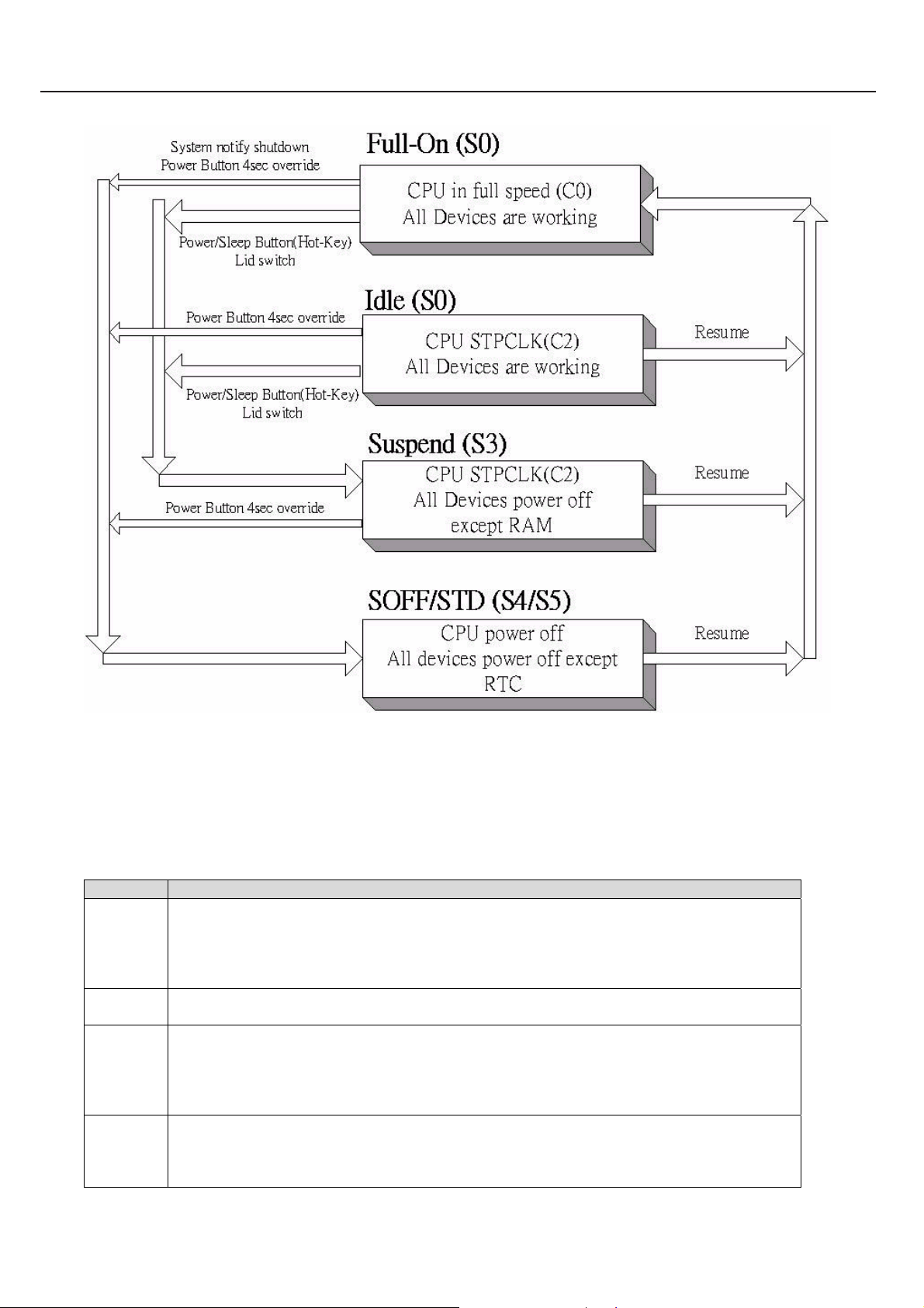
2.6.2 Power Management State Transition
223II0 Rev : A Page 18 - 27
19
Page 20
TECHNICAL SERVICE MANUALPrestigio Visconte120
2.6.3 Power Management Mode Definitions
Each system (or model) may have different PM model and state definition. For clear, see the following table :
PM Mode Definitions
Full-On The CPU runs in full speed and all the devices are power on. The system can respond to all
applications with maximum performance.
1. The system is in the state S0.
2. The CPU is in the state C0.
3. All the devices are in the state D0.
Geyserville
III
Idle This mode is similar to Full-On . The CPU might change into C1 or C2 state depend on the OS, in
Suspend The state is more power saving than above, the CPU and most of parts power will be cut off except
223II0 Rev : A Page 19 - 27
CPU will running between diffenent BUS ratio depend on system loading, if power Schemes set to
Presentation or Max Battery
order to save CPU power consumption.
1. The system is in the state S0.
2. The CPU is in the state C1 or C2.
3. All the devices are in the state D0.
DRAM system.
1. The system is in the state S3.
2. The CPU and all of devices are power off except DRAM system.
20
Page 21
TECHNICAL SERVICE MANUAL Prestigio Visconte120
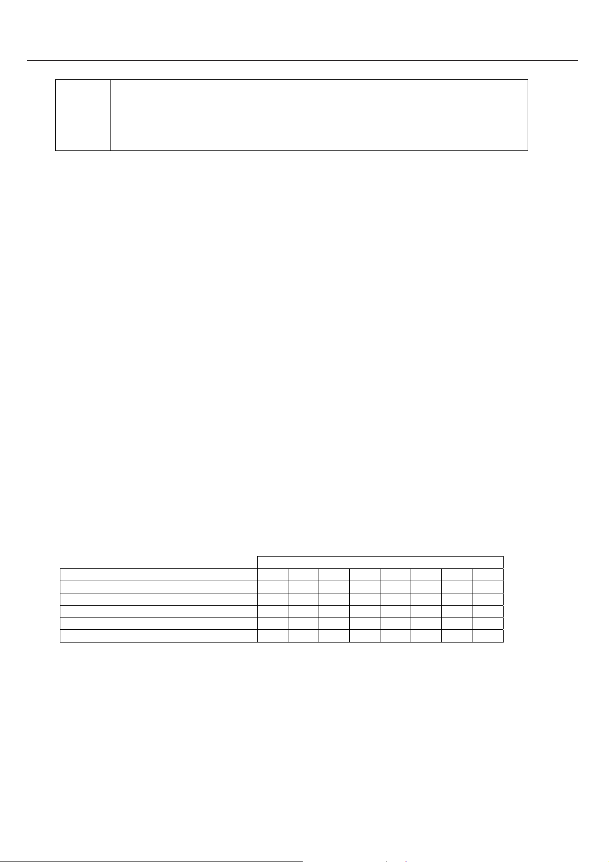
SOFF/STD The state is the most power saving mode, all of the parts in the system will power off, except the
keyboard controller enter to idle mode continuously to control the battery charging and monitor power
button.
Note: Before enter to S4, the OS will save all of data or registers in HDD.
1. The system is in the state S5 or S4.
2. The CPU and all of devices are power off.
When system is in suspend mode (S3 state ), external keyboard/mouse and touch pad cannot be the wake up event source.
Use Power button or Lid to resume.
2.6.4 Uniwill Smart Power Function
The purpose of Smart Power is to save the power consumption during the system is not busy. This function not only save the
power of Battery to extend the Notebook’s battery working time, but also reduce the the temperature of CPU / Chip and keep
system working in a lower temperature to extend the CPU and whole system’s life. Reduce temperature will also keep
Operation System work stable.
2.6.4.1 Instant On Mode: If press Instant On button to power on, CPU ext. clock will keep at 66MHz,
CPU bus ratio will keep at the minimum.
2.6.4.2 Long Battery Life Mode: Also called Smart Power 1, CPU ext. clock will keep at 100MHz, CPU
maximum bus ratio will keep at the most lower level 4 when battery mode detected (ex. Banias 1. 7G 6
point will keep maximum at level 2, Dothan 1.8G 7 point will keep maximum at level 3). This option can
be enabled/disabled by CMOS setup.
2.6.4.3 High Performance Mode: Also called Smart Power 2, CPU ext. clock will increase to 115MHz,
CPU bus ratio will keep as Pemtium M CPU default when AC mode detected. This option can be
enabld/disabled by CMOS setup.
Silent Mode: The FAN will stop or run at very low speed to keep system slient. In Windows XP OS press
Instant On button will toggle Silent mode. CPU ext. clock will decrease to 80MHz, CPU bus ratio will
keep at the minimun no matter AC mode or Battery mode when Silent mode enabled.
2.6.4.4 Pentium M CPU bus ratio table:
CPU Bus Ratio level
CPU type 0 1 2 3 4 5 6 7
Banias 1.7GHz 6 points for B1 17 14 12 10 8 6 NA NA
Banias 1.4GHz 5 points for B1 14 12 10 8 6 NA NA NA
Dothan 2.0GHz 8 points for B1 20 18 16 14 12 10 8 6
Dothan 1.8GHz 7 points for B1 18 16 14 12 10 8 6 NA
Dothan 1.7GHz 6 points for B1 17 14 12 10 8 6 NA NA
2.6.5 CPU Fan Control
In the system use the fan as the active cooling device. It is not necessary always turn on full speed, so following will
depict the method and specification of fan speed control. Before it we would like to define the fan speed:
Please refer to SmartPower Management Software Designer’s Guide
223II0 Rev : A Page 20 - 27
21
Page 22

TECHNICAL SERVICE MANUALPrestigio Visconte120
Because fan will consume some power and make some noise, the system will try to keep the fan in low speed and keep the
system in high performance as possible. Unfortunately, there are some trade-off among some factors: thermal, noise and CPU
performance, so we increase the fan speed as active cooling method and triger the CPU clock throttling as passive cooling
method. The CPU clock and fan speed is controlled depend on the CPU temperature from hardwire thermal monitor.
2.6.6 The backlight control of LCD
The LCD panel is another key parts that will consume more power of the notebook system, so there is a way to reduce the
power consumption on battery only, e.i. reduce the brightness of backlight when end-user unplug the AC adaptor.
The backlight is controled through the KBC controller, and it is divide into 8 levels from darkest to brightest. The KBC
bios know the status of power source and the current backlight’s brightness any time. When the AC adaptor unplug, the KBC
will reduce the brightness one or two level automatically.
There is another approach to control the backlight, it will be turn off when LCD cover is close (LID switch), conversely,
it will be turn on when LCD cover is open
2.7.1 Crisis Disk
Crisis Disk function can recover the BIOS back if flash BIOS fail and can’t boot up due to lost power while BIOS flashing or
any other situations. Operation as below:
2.7.1.1 Crisis Disk options: There’re 3 kinds of Crisis Disk options (Press Key Conbine) as below
2.7.1.2Ctrl-Home: NVRAM data (DMI string) will be preserved, CMOS data will be destroyed after
flash.
2.7.1.3 Ctrl-PageDown: both NVRAM and CMOS data will be preserved.
2.7.1.4 Ctrl-PageUp: both NVRAM and CMOS data will be destroyed.
2.7.1.5 The correct way to press these combine key is, Press and Hold “Ctrl” key, then Press and
release the second key (ex. Home) several times.
2.7.2 Prepare a Floppy Disk contain BIOS ROM file
2.7.2.1 Complete Format a Floppy Disk, to make sure there’s no bad sector
2.7.2.2 Rename the BIOS ROM filename to “AMIBOOT.ROM” and copy this file into the Floppy Disk
2.7.2.3 Insert the Floppy Disk into USB Floppy Disk Drive
2.7.2.4 Insert the USB Floppy Disk Drive into any USB port
223II0 Rev : A Page 21 - 27
22
Page 23

TECHNICAL SERVICE MANUAL Prestigio Visconte120
2.7.3 Start to flash BIOS with Crisis Disk Function
2.7.3.1Insert AC adaptor, in case the Battery is too low to shutdown during flashing BIOS
2.7.3.2 Press Power Button to turn on power
2.7.3.3 Press “Crisis Disk option key” (ex. Ctrl-Home) several times
2.7.3.4 Watch the USB Floppy Disk Drive is accessing a while
2.7.3.5 Screen will show a “Starting FLASH Recovery.” message while flashing BIOS
2.8 CMOS Setup Menu
The setup function only can be invo ked by pressing F2 key during POST that provide a appr oach to change som e setting and
configuration the user prefer, and the changed values will save in the battery backu p RAM of CMOS RTC and will take effect
after the system rebooted. The setup uses a menu interface to allow the user to configure their system and the features are briefly
listed as follow
Press F12 key for Boot Menu
2.8.1 Main Menu
BIOS SETUP UTILITY
Main Advanced Security Power Boot Exit
System Overview
BIOS Information
BIOS Version : (OEM BIOS Version)
KBC Version : (OEM KBC Version)
Build Date : (BIOS build date)
Processor
Type : (detected Intel CPU type xxxx)
Speed : (detected CPU real Speed)
System Memory
Size : (detected memory size xxxMB)
System Tim e [00:00:00]
System Date [Tue 01/01/2003]
V02.54 (C)Copyright 1985-200 2, American Megatrends, Inc.
2.8.2 Advanced Menu
Use [Enter], [Tab]
Or [SHIFT-TAB] to
Select a field..
Use [+] or [-] to
Configure system Time.
←→ Select Screen
↑↓ Select Item
+- Change Field
Tab Select Field
F1 General Help
F10 Save and Exit
ESC Exit
223II0 Rev : A Page 22 - 27
23
Page 24

BIOS SETUP UTILITY
Main Advanced Security Power Boot Exit
Advanced Settings
WARNING: Setting wrong values in below sections
May cause system to malfunction.
>IDE Configuration
TouchPad Support [Auto]
Internal Modem Support [Enable]
LCD AutoDimm Function [Enabled]
Mini PCI Wireless LAN [Enabled]
V02.54 (C)Copyright 1985-200 2, American Megatrends, Inc.
TECHNICAL SERVICE MANUALPrestigio Visconte120
Configure the IDE
device(s)
←→ Select Screen
↑↓ Select Item
Enter Go to Sub Screen
F1 General Help
F10 Save and Exit
ESC Exit
2.8.3 Advanced -> IDE Configuration
BIOS SETUP UTILITY
Main Advanced Security Power Boot Exit
IDE Configuration
> Primary IDE Master : [Hard Disk]
> Secondary IDE Master : [ATAPI CDROM]
V02.54 (C)Copyright 1985-200 2, American Megatrends, Inc.
While entering setup,
BIOS auto detects the
Presence of IDE
devices. This displays
the status of auto
detection of IDE
devices.
←→ Select Screen
↑↓ Select Item
Enter Go to Sub Screen
F1 General Help
F10 Save and Exit
ESC Exit
2.8.4 Advanced -> IDE Configuration -> Primary IDE Master
BIOS SETUP UTILITY
223II0 Rev : A Page 23 - 27
24
Page 25

TECHNICAL SERVICE MANUAL Prestigio Visconte120
Main Advanced Security Power Boot Exit
Primary IDE Master
Device :Hard Disk
Vendor :FUJITSU MHT…..
Size :40.0GB
LBA Mode :Supported
Block Mode :16Sectors
PIO Mode :4
Async DMA :MultiWord DMA-2
Ultra DMA :Ultra DMA-5
S.M.A.R.T. :Supported
Select the type
Of device connected
To the system.
←→ Select Screen
↑↓ Select Item
+- Change Option
F1 General Help
F10 Save and Exit
ESC Exit
V02.54 (C)Copyright 1985-200 2, American Megatrends, Inc.
2.8.5 Advanced -> IDE Configuration -> Secondary IDE Master
BIOS SETUP UTILITY
Main Advanced Security Power Boot Exit
Secondary IDE Master
Device :ATAPI CDROM
Vendor :QSI CD-RW/DVD-ROM…
LBA Mode :Supported
PIO Mode :4
Async DMA :MultiWord DMA-2
Ultra DMA :Ultra DMA-2
V02.54 (C)Copyright 1985-200 2, American Megatrends, Inc.
Select the type
Of device connected
To the system.
←→ Select Screen
↑↓ Select Item
+- Change Option
F1 General Help
F10 Save and Exit
ESC Exit
2.8.5 Security Menu
BIOS SETUP UTILITY
Main Advanced Security Power Boot Exit
223II0 Rev : A Page 24 - 27
25
Page 26

Security Settings
Supervisor Password :Not Installed
User Password :Not Installed
Change Supervisor Password
Change User Password
Clear User Password
Boot Sector Virus Protection [Disabled]
V02.54 (C)Copyright 1985-200 2, American Megatrends, Inc.
TECHNICAL SERVICE MANUALPrestigio Visconte120
Install or Change the
Password.
←→ Select Screen
↑↓ Select Item
Enter Change
F1 General Help
F10 Save and Exit
ESC Exit
2.8.6 Power Menu
BIOS SETUP UTILITY
Main Advanced Security Power Boot Exit
Power Settings
Intel( R ) SpeedStep( tm ) tech. [Automatic]
Power Button Mode [Suspend]
Long Battery Life Mode [Disable]
High Performance Mode [Disable]
V02.54 (C)Copyright 1985-200 2, American Megatrends, Inc.
Depending on AC or
Battyery powered, CPU
Speed will change
based on the selections
←→ Select Screen
↑↓ Select Item
+- Change Option
F1 General Help
F10 Save and Exit
ESC Exit
2.8.7 Boot Menu
BIOS SETUP UTILITY
223II0 Rev : A Page 25 - 27
26
Page 27

TECHNICAL SERVICE MANUAL Prestigio Visconte120
Main Advanced Security Power Boot Exit
Boot Settings
Quiet Boot [Enabled] (depend on OEM logo)
> Boot Device Priority
V02.54 (C)Copyright 1985-200 2, American Megatrends, Inc.
Configure Settings
During System Boot.
←→ Select Screen
↑↓ Select Item
Enter Go to Sub Screen
F1 General Help
F10 Save and Exit
ESC Exit
2.8.8 Boot -> Boot Device Priority
BIOS SETUP UTILITY
Main Advanced Security Power Boot Exit
Boot Device Priority
1st Boot Device [Removable Dev.]
2nd Boot Device [CD/DVD]
3rd Boot Device [Hard Drive]
4th Boot Device [Realtek Boot Agent]
V02.54 (C)Copyright 1985-200 2, American Megatrends, Inc.
2.8.9 Exit Menu
Allows BIOS to skip
Certain tests while
Booting. This will
Decrease the time
Needed to boot the
System.
←→ Select Screen
↑↓ Select Item
+- Change Option
F1 General Help
F10 Save and Exit
ESC Exit
BIOS SETUP UTILITY
Main Advanced Security Power Boot Exit
Exit Options Exit system setup
223II0 Rev : A Page 26 - 27
27
Page 28
Save Changes and Exit
Discard Changes and Exit
Discard Changes
Load Optimal Defaults
TECHNICAL SERVICE MANUALPrestigio Visconte120
After saing the
Changes.
F10 key can be used
For this operation.
←→ Select Screen
↑↓ Select Item
Enter Go to Sub Screen
F1 General Help
F10 Save and Exit
ESC Exit
V02.54 (C)Copyright 1985-200 2, American Megatrends, Inc.
2.8.10Load Optimal Defaults
Press “F9” can load optimal defaults.
Load Optimal Defaults?
[Ok] [Cancel]
2.8.11 Save Changes and Exit
Press “F10” can save changes and Exit
Save configuration changes and exit setup?
[Ok] [Cancel]
223II0 Rev : A Page 27 - 27
28
Page 29
TECHNICAL SERVICE MANUAL Prestigio Visconte120
29
Page 30

TECHNICAL SERVICE MANUALPrestigio Visconte120
2.1. System Block Diagram …………………………………………………...
2.2. Major Component Definition.……..……………………………….……
2.3. Connector Definition…….………………………………………………..
2.4. Major Components And Connectors Location………………………….
30
Page 31

TECHNICAL SERVICE MANUAL Prestigio Visconte120
2.1. System Block Diagram
31
Page 32

2.2. Major Component Definition
TECHNICAL SERVICE MANUALPrestigio Visconte120
CPU Socket (U38A)
32
Page 33

TECHNICAL SERVICE MANUAL Prestigio Visconte120
CPU Socket (U38B)
33
Page 34

CPU Socket (U38C)
TECHNICAL SERVICE MANUALPrestigio Visconte120
34
Page 35

TECHNICAL SERVICE MANUAL Prestigio Visconte120
CPU Socket (U38D)
35
Page 36

Intel 855 GME (U19A)
TECHNICAL SERVICE MANUALPrestigio Visconte120
36
Page 37

TECHNICAL SERVICE MANUAL Prestigio Visconte120
Intel 855 GME (U19B)
37
Page 38

Intel 855 GME (U19B)
TECHNICAL SERVICE MANUALPrestigio Visconte120
38
Page 39

TECHNICAL SERVICE MANUAL Prestigio Visconte120
Intel 855 GME (U19D)
39
Page 40

Intel 855 GME (U19E)
TECHNICAL SERVICE MANUALPrestigio Visconte120
40
Page 41

TECHNICAL SERVICE MANUAL Prestigio Visconte120
Main Clock Generator (U22) Clock Buffer (DDR) U25
41
Page 42

TI 1410 (U24)
TECHNICAL SERVICE MANUALPrestigio Visconte120
42
Page 43

TECHNICAL SERVICE MANUAL Prestigio Visconte120
TSB43AB22A (U44)
43
Page 44

ICH4-M –(U23A)
TECHNICAL SERVICE MANUALPrestigio Visconte120
44
Page 45

TECHNICAL SERVICE MANUAL Prestigio Visconte120
ICH4-M –(U23B)
45
Page 46

ICH4-M –(U23C)
TECHNICAL SERVICE MANUALPrestigio Visconte120
46
Page 47

TECHNICAL SERVICE MANUAL Prestigio Visconte120
MAX1907(U1)
Amplifier TPA601 1A4 (U21) VT1612A (U20)
47
Page 48

IT8510E (U46)
TECHNICAL SERVICE MANUALPrestigio Visconte120
48
Page 49

TECHNICAL SERVICE MANUAL Prestigio Visconte120
LAN (U28)
49
Page 50

TECHNICAL SERVICE MANUALPrestigio Visconte120
Main Clock Generator (U22) ICS 91718 (U25)
50
Page 51

TECHNICAL SERVICE MANUAL Prestigio Visconte120
Flash ROM (U43)
51
Page 52

2.3. Connector Definition
TECHNICAL SERVICE MANUALPrestigio Visconte120
Memory DDR_DIMM (CON18)
52
Page 53

TECHNICAL SERVICE MANUAL Prestigio Visconte120
Memory DDR_DIMM (CON17)
53
Page 54

LCD Connector (CON2)
Inverter (CON1)
TECHNICAL SERVICE MANUALPrestigio Visconte120
54
Page 55

TECHNICAL SERVICE MANUAL Prestigio Visconte120
S-Video (CON14)
55
Page 56

PCMCIA_SOCKET (CON9)
TECHNICAL SERVICE MANUALPrestigio Visconte120
56
Page 57

TECHNICAL SERVICE MANUAL Prestigio Visconte120
MIC Jack (CON20)
Speaker Jack (CON19) & R/L Speaker (CON22)
57
Page 58

Modem CON (CON28)
TECHNICAL SERVICE MANUALPrestigio Visconte120
CRT Connector (CON5) LAN RJ45/Modem phone (CON12)
58
Page 59

TECHNICAL SERVICE MANUAL Prestigio Visconte120
T/P (CON26)
USB CONN (CON6)
59
Page 60

USB_BT_CON (CON23)
TECHNICAL SERVICE MANUALPrestigio Visconte120
USB_BOARD_CON (CON10)
60
Page 61

TECHNICAL SERVICE MANUAL Prestigio Visconte120
Primary Driver HDD (CON24)
61
Page 62

Secondary Driver (Master) CD-ROM (CON16)
TECHNICAL SERVICE MANUALPrestigio Visconte120
MDC Connector (CON25) Internal KB (CON4)
62
Page 63

TECHNICAL SERVICE MANUAL Prestigio Visconte120
LED CONN (CON10) Power Switch&LED (CON29)
Fan_CON (CON13)
Battery (CON15) &Adapter(CON11)
63
Page 64

TECHNICAL SERVICE MANUALPrestigio Visconte120
64
Page 65

TECHNICAL SERVICE MANUAL Prestigio Visconte120
2.4.
Major Components And Connectors Location
65
Page 66

TECHNICAL SERVICE MANUALPrestigio Visconte120
66
Page 67

TECHNICAL SERVICE MANUAL Prestigio Visconte120
67
Page 68

3.1. Top Cabinet & MB Assembly & Keyboard & Battery……………
3.2. Bottom Cabinet & HDD Assembly & Cover Door……..…………...
3.3. LCD Module Assembly………………..
TECHNICAL SERVICE MANUALPrestigio Visconte120
68
Page 69

TECHNICAL SERVICE MANUAL Prestigio Visconte120
3.1. Top Cabinet & MB Assembly & Keyboard & Battery
69
Page 70

3.2. Bottom Cabinet & HDD Assembly & Cover Door
TECHNICAL SERVICE MANUALPrestigio Visconte120
70
Page 71

TECHNICAL SERVICE MANUAL Prestigio Visconte120
No. PART NUMBER DESCRIPTIONE QT
Y
1 71-UF 4012-00 K/B W/F2 ICON #8006 US 86KEY JME 223IIX
2 50-UF 4053-00 COVER HINGE 223 #8017
3 83-UF 4010-01 TOP CAB ASSY #8017/8100 223II0 R01
4 50-UF 4100-10 LENS R TOP BASE 223 #8017
5 50-UF 4100-00 LENS L TOP BASE 223 #8017
6 23-UF 40D0-3A BAT 223 LI SMP 4SIP SAM 2.2AH 1A
7 83-UF 4050-01 BRACKET ASSY TOP HOSING 223II0 R01
8 82-UF 4000-01 M/B BD ASSY 223II0 REV:01
9 80-UF 4020-01 CRT BD ASSY 223II0 REV:01
10 80-UF 4030-01 CARD READER BD ASSY 223II0 REV.01
11 80-UF 4050-01 SW BD ASSY 223II0 REV.01
12 76-063200-01 MDC MODEM CARD MM320 CASTLENET
1
1
1
1
1
1
1
1
1
1
1
1
R01
13 29-UF 4030-00 FPC TOUCHPAD SWITCH 223II0
14 29-UF 4031-00 FPC LED FUNCTION 223II0
15 29-UF 4042-00 FFC SWITCH PCB 223II0
16 29-UF 4040-00 FFC CARDREADER 223II0
17 29-UF 4041-00 FFC CRT PCB 223II0
18 29-UF 4070-00 CABLE USB PCB 223II0
19 29-UF 4083-00 CABLE MODEM 223II0
20 22-300528-00 SPACKER BASE ID0 223II0
21 50-UD4059-00 COVER PCMCIA DUMMY CARD #8098 755
22 40-UF 4040-00 THERMAL MODULE FOR 223(YDT& BI)
23 83-UF 4051-00 BRACKET ASSY HDD HOLDER 223
24 83-UF 4020-21 BOTTOM CAB ASSY #8155 223II0 R.01
25 83-UF 4091-20 DOOR PCI ASSY #8155 223II0
26 83-UF 4090-21 DOOR BIG ASSY #8155 223II0 R01
27 73-080084-00 TO UCHPAD TM42PDZ371 SYNAPTICS 223II0
28 83-UF 4042-40 BEZEL ASSY DVD-ROM #8155 QSI 223
29 40-UF 4027-00 BRACKET ODD LOCK 223II0
30 70-200001-30 ODD DVD-ROM 8X SDR-083 QSI FW:MU06
31 70-822040-10 HDD 40GB MK4025GAS TOSHIBA
1
1
1
1
1
1
1
1
1
1
1
1
1
1
1
1
1
1
1
71
Page 72

3.3. LCD Module Assembly
TECHNICAL SERVICE MANUALPrestigio Visconte120
72
Page 73

TECHNICAL SERVICE MANUAL Prestigio Visconte120
No. PART NUMBER DESCRIPTIONE QTY
1 50-UF4041-00 BACK CAB LCD WIDE 223 1
2 50-UF4090-00 LATVH LCD 223 1
3 40-UF4031-00 SHIELDING-SPONGE WIDE 223 1
4 29-UF4050-00 CABLE LCD AU WIDE 223 1
5 76-030003-3A INVERTER SAMPO DIVTN0003-D11-R:3A 1
6 50-U98211-00 MYLAR INVERTER N355V1 1
7 29-UF4082-00 CABEL INV-MIC-SPK ASSY WIDE 223 1
8 72-112260-00 LCD 12.1” TFT B121EW01 VO WXGA AU 1
73
Page 74

TECHNICAL SERVICE MANUALPrestigio Visconte120
9 40-UF4050-20 HINGE-L AU WIDE 223 1
10 40-UF4051-20 HINGE-R AU WIDE 223 1
11 22-300062-00 SPK-MIC ASSY GRM-62A WIDE 223 1
12 51-UF4020-00 SPONGE SPK WIDE 223 2
13 40-UF4800-00 MAGNET 13*5*4 223 1
14 50-UF4031-00 FRONT CAB LCD AU WIDE 223 1
15 52-UF4030-00 RUBBER LCD 223 4
16 50-UF4213-00 MYLAR-NET SPK LCD 223 1
17 41-720120-03 SCREW M2.0*3 I #1 NI 10
18 41-720525-04 SCREW M2.5*4 D4.1 T0.6 NI+NYLOK I 6
19 41-720B02-04 SCREW M2.0*4 D4.5 I#1 BZ 4
20 41-720B25-05 SCREW M2.5*5 I#1 BZ NYLOK 2
74
Page 75

TECHNICAL SERVICE MANUAL Prestigio Visconte120
75
Page 76

TECHNICAL SERVICE MANUALPrestigio Visconte120
4.1. System Disassembly Procedures……………………………………………
4.2. LCD Display Panel Disassembly Procedure………………….…………...
76
Page 77

TECHNICAL SERVICE MANUAL Prestigio Visconte120
4.1. System Disassembly Procedures
Please refer to the disassembly procedures
of the 223II0.
1. Open the battery lock firstly.
2. Open the another lock and take off the
battery pack.
77
Page 78

TECHNICAL SERVICE MANUALPrestigio Visconte120
3. Unfasten nine (9) screws and pull out the
CPU cover. Open the lock of USB port
cover and pull off the cover.
4. Unfasten three (3) screws of the thermal
module and disconnect the CPU fan cable.
5. Open the CPU socket lock in
counterclockwise direction and remove the
CPU.
78
Page 79

TECHNICAL SERVICE MANUAL Prestigio Visconte120
6. Remove the DDR RAM.
7. Pull off the hard disk device.
8. Unfasten two (2) screw .
79
Page 80

TECHNICAL SERVICE MANUALPrestigio Visconte120
9. Remove the wireless card cover.
10. Disconnect the antenna cable and
remove wireless card.
11. Pull out the optical device
80
Page 81

TECHNICAL SERVICE MANUAL Prestigio Visconte120
12. Unfasten eleven (11) screws of the
bottom.
13. Unlock three (3) latches of the
Keyboard.
14. Disconnect keyboard cable and remove
the keyboard.
81
Page 82

TECHNICAL SERVICE MANUALPrestigio Visconte120
15. Remove the left and right hinge covers.
16. Unfasten for (4) screws.
17. Disconnect the LCD cable and Inverter
cable.Then remove the whole LCD module
82
Page 83

TECHNICAL SERVICE MANUAL Prestigio Visconte120
18. Gently disassemble the bottom from the
system.
19. Disconnect Modem, Speaker and USB
BD cable. Then unfasten four (4) screws of
Speaker and two (2) screws of USB BD..
20. Unfasten one (1) hex nut and remove
the Modem BD.
83
Page 84

TECHNICAL SERVICE MANUALPrestigio Visconte120
21. Disconnect the CardReader BD cable.
Then unfasten one (1) screw and one (1)
hex nut.
22. Remove the CardReader BD
23. Disconnect the CRT BD cable and
unfasten one (1) screw.
84
Page 85

TECHNICAL SERVICE MANUAL Prestigio Visconte120
25. Unfasten two (2) screws and remove
the CRT BD.
26. Disconnect the CRT cable on the MB
and TouchPad cable. Unfasten six (6)
screws and four (4) hex nuts.
27. Gently remove the main board from the
top house.
85
Page 86

28. System disassembly finished.
TECHNICAL SERVICE MANUALPrestigio Visconte120
86
Page 87

TECHNICAL SERVICE MANUAL Prestigio Visconte120
4.2. LCD Display Panel Disassembly Procedure
1. Remove two (2) rubber stoppers and
unfasten 2 (2) screws .
2. Gently
(2) screws both sides.
3. Gently disassemble the LCD front
cabinet.
undraw mylar-net and unfasten 2
87
Page 88

TECHNICAL SERVICE MANUALPrestigio Visconte120
4. Unfasten two (2) screws and disconnect
three cables. Then remove the Inverter BD.
5. Unfasten four (4) screws on the Speaker.
6. Unfasten six (6) screws
88
Page 89

TECHNICAL SERVICE MANUAL Prestigio Visconte120
7. Remove LCD panel from LCD back
cabinet.
8. Disconnect the LCD cable.
9. Unfasten 4 (4) screws and remove the
right & left LCD bracket.
89
Page 90

TECHNICAL SERVICE MANUALPrestigio Visconte120
10. LCD display panel disassembly
finished.
90
Page 91

TECHNICAL SERVICE MANUAL Prestigio Visconte120
91
Page 92

TECHNICAL SERVICE MANUALPrestigio Visconte120
5.1. CPU, RAM, HDD Installation……………………………………………
5.2. Upgrade System & Keyboard BIOS…………..…………….…………...
92
Page 93

TECHNICAL SERVICE MANUAL Prestigio Visconte120
5.1. CPU, RAM, HDD Installation
Warning Notice
For precautionary measures, please disconnect the AC adapter and remove the battery from the
battery compartment while doing the installation procedure of the CPU, Memory & HDD.
Procedure to remove the battery
1. 1. Open the battery lock firstly.
2. Open the another lock and take off the
battery pack.
93
Page 94

TECHNICAL SERVICE MANUALPrestigio Visconte120
A. CPU Installation Guide
Important Notice
The CPU thermal pad of the CPU fan heat sink (black color) is one time use only. Meaning
that if you remove the CPU heat sink from the CPU, you must REPLACE the CPU thermal
pad with a new thermal pad (black color). Clean any residue on the CPU and the CPU heat
sink assembly before putting the new CPU thermal pad. Otherwise, there might be an overheat
problem on the CPU.
1. Unfasten nine (9) screws and pull out the
CPU cover.
2. Unfasten three (3) screws of the thermal
module and disconnect the CPU fan cable
3. Open the CPU socket lock.
94
Page 95

TECHNICAL SERVICE MANUAL Prestigio Visconte120
4. Align the Pin 1 of CPU with Pin 1 of
CPU socket and gently put the CPU into
the CPU socket.
5. Lock the CPU socket clockwise.
6. Put back the CPU heat sink assembly
and fasten the three (3) screws and connect
the fan cable.
95
Page 96

B. HDD Module Installation Guide
TECHNICAL SERVICE MANUALPrestigio Visconte120
1. Fasten four (4) screws of HDD module.
2. Push the HDD bracket into the HDD
socket.
C. Memory Module Installation Guide
1. Gently assemble the DDR RAM module
96
Page 97

TECHNICAL SERVICE MANUAL Prestigio Visconte120
5.2. Upgrade the BIOS
Important Notice
The utility only support at real mode (DOS mode), can not run at the protected mode (Window
Mode). Do make sure that the system boot from real mode and plug AC power when to update the
BIOS or install the utility.
BIOS Update Procedure
The F82741.EXE utility is used to flash the system ROM and upgrade the BIOS.
1. Make sure the AC adapter is connected to your notebook before you run this utility.
2. Please make a clean Boot Disk which has no config.sys and autoexec.bat files.
3. Boot from Floppy disk, enter DOS prompt.
4. Type
DIR
5. Please make sure the diskette has the following files :
F82741.EXE and xxxx.xxx (Bios Filename)
6. Start to update the system BIOS,
AC power must plug into unit. Type
A:\F82741 xxxx.xxx
7. Press Enter. After updating the bios, please
go to BIOS setup and load DEFAULT setting.
The system reboots automatically after installation is complete.
97
Page 98

TECHNICAL SERVICE MANUALPrestigio Visconte120
98
Page 99

TECHNICAL SERVICE MANUAL Prestigio Visconte120
Trouble Shooting List
6.1 No display
6.2 VGA controller failure
6.3 LCD no display / Invalid picture
6.4 External monitor has no display or color incorrect
6.5 Memory test error
6.6 Keyboard test error
6.7 Touch pad test error
6.8 Memory Card bus Failure
6.9 Hard disk drive test error
6.10 CMOS test error
6.11 IEEE 1394 Failure
6.12 PIO port test error
6.13 Audio failur e
6.14 No power symptom
6.15 CD ROM drive test error
6.16 Stopping in LCD screen while booting
6.17 PCMCIA Card Bus failure
6.18 IR Port cannot transfer data
6.19 Modem Failure
6.20 LAN Failure
6.21 TV OUT Failure
6.22 Battery Failure
6.23 USB Port Failure
99
Page 100

TECHNICAL SERVICE MANUALPrestigio Visconte120
6.1 No display (system failure)
Symptom: There is no display on both LCD and Monitor after power on although
the LCD and Monitor are known-good.
No Display
Monitor or LCD module ok?
DDR RAM module ok?
CPU OK??
Display Ok?
NO
Replace monitor or LCD
Yes
NO
Replace DDR module
Yes
Yes
NO
Replace CPU
Yes
Yes
Correct it
No
Replace motherboard
100
 Loading...