

Prestigio PSP3502 Service Manual

SERVICE MANUAL
For Cellular Phone
Model Name: PSP3502
Version: A
Effective Date: 2014.04.27

Note:
This manual is guide to after-sales repair of DA34681 mobile phone, the repair
of product shall only be carried out by trained and well experienced technical
person and use of this manual by any other person for the service of the
product may result in serious damage to the product

Content
1. Introduction
1.1 Purpose
1.2 General safety Guidelines and use
2. General Characters
2.1 Overview
2.2 Introduction to main Functions
3. Introduction to capability and index
4. How the GSM system work
4.1 General
4.2 Introduction of GSM
5. System overview
5.1 RF Part
5.2 BB part
6. Assembl y and Disassembly
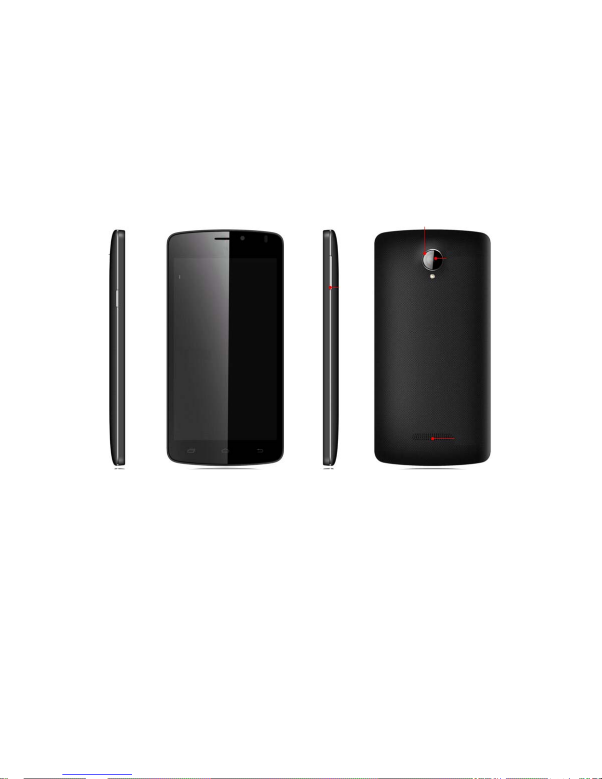
6.1 product appearance
6.2 Introductions of disassembly
7. Rep air requirement
8. Baseband Trouble
8.1 Flash programming does not download
8.2 Phone does not “power on”
8.3 Sound trouble
8.4 Can not charge up
8.5 LCD trouble
8.6 Microphone trouble
8.7 Earphone part trouble
8.8 Vibrator trouble
8.9 Receiver does not work
8.10 Camera trouble
8.11 WIFI and FM and BT and GPS circuit trouble
8.12 G-sensor has not function
8.13 Phone can not access SIM card
8.14 TF card trouble and TF card Circuit Working Principle

9. RF Trouble
9.1 Principle of operation
9.2 AGC failure
9.3 AFC failure
9.4 APC Failure
10. Maintenance tools
1. Introduction:
1.1 Purpose:
The main purpose of this manual is to provide a basic foundation for electrical
and mechanical repairs
1.2 General Safety guidelines and use:
Safety guidelines:
The product contains polar capacitors, which must not be short-circuited or
connected with polarities reversed. During repairs, due attention shall be paid
to static protection in order not to damage the ESD-sensitive components of
this device. It is strictly forbidden to use mobile phone dial up in the plane. It is
strictly forbidden to use this device near aerosol sprays or explosive gases
Use of mobile phone:
Please do not make mobile phone approach or touch the exposed parts of the
body(especially face or eye), If the user holds the mobile phone like the
receiver of a common telephone, it has best efficiency when its antenna is
upwards and above the shoulder. Please speak to microphone.
Each driver shall always pay attention to safety, Use of a mobile phone when
she/he drives in some areas is an illegal act.
2. General characters
:
2.1 Overview:
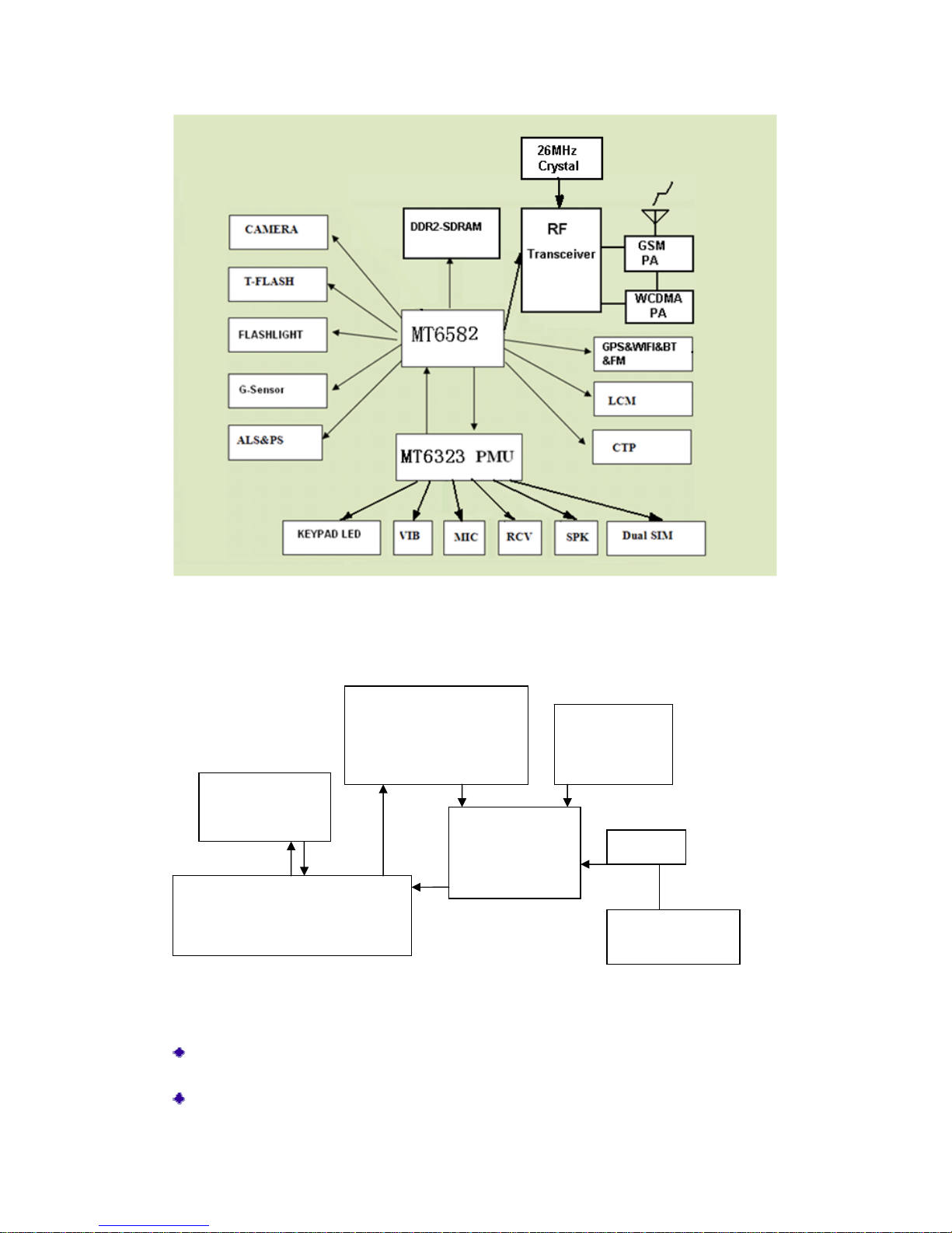
DA34681 mobile phone are based upon platform MT6582, including baseband
circuit and frequency circuits, Baseband parts is mainly comprised of master
chip MT6582 and its controlled peripheral circuits. DA34681 is equipped with
dual SIM and dual standby, double camera, single battery, CTP,G-sensor,
WIFI,FM, Bluetooth and single memory card.
Main Features:
Main dimension: 146*73*10.1 mm
Smart phone
Optional band (GSM 900 \ 1800 \ 850 \ 1900\W2100)
Display: 5.0’HD
Camera: 8M\5M image elements
Voice recording

Antenna: GSM antenna, FM earphone antenna, BT/WiFi/GPS antenna
Charger: Micro USB charger
SIM: dual band and dual standby
Support MSN, Yahoo, Message, face book, ect
3. Introduction to capability and index:
Operating temperature: -10℃ ~ +55℃
Storage temperature: -10 ℃ ~ +60℃
Relative humidity: 10% ~ 95%
Transmit power: Class 4(2W)/(EGSM/GSM850)
Class 1(1W)/(DCS/PCS)
Class 3(200mW)(W2100/W850)
Voltage range: 3.7 ~ 4.2V
Battery capacity: 1850mAh
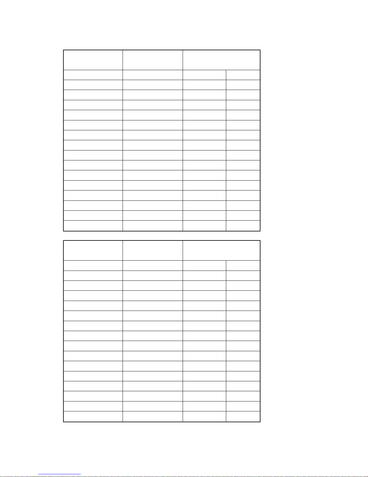
Item GSM Technical Indexes DCS Technical Indexes
Frequency Range
Transmit : 880~915MHz
Receiver : 925~960MHz
Transmit: 1710~1785MHz
Receiver: 1805~1880MHz
Channel
174 Carrier wave, 8 channels
per carrier wave
174 Carrier wave, 8 channels per
carrier wave
Phase Error
RMS Less than 5 degrees, Peak
value less than 20 degrees
RMS Less than 5 degrees, Peak
value less than 20 degrees
Bit Error Rate <2% <2%
Receiving Sensitivity <-102dBm <-102dBm
Voltage Range 3.2~4.5V
Temperature Range —10℃ ~+55 ℃
Item GSM850 Technical Indexes PCS Technical Indexes
Frequency Range
Transmit : 824~849MHz
Receiver : 869~894MHz
Transmit: 1850~1910MHz
Receiver: 1930~1990MHz
Channel
174 Carrier wave, 8 channels
per carrier wave
174 Carrier wave, 8 channels per
carrier wave
Phase Error
RMS Less than 5 degrees, Peak
value less than 20 degrees
RMS Less than 5 degrees, Peak
value less than 20 degrees
Bit Error Rate <2% <2%
Receiving Sensitivity <-102dBm <-102dBm
Voltage Range 3.2~4.5V
Temperature Range —10℃ ~+55 ℃
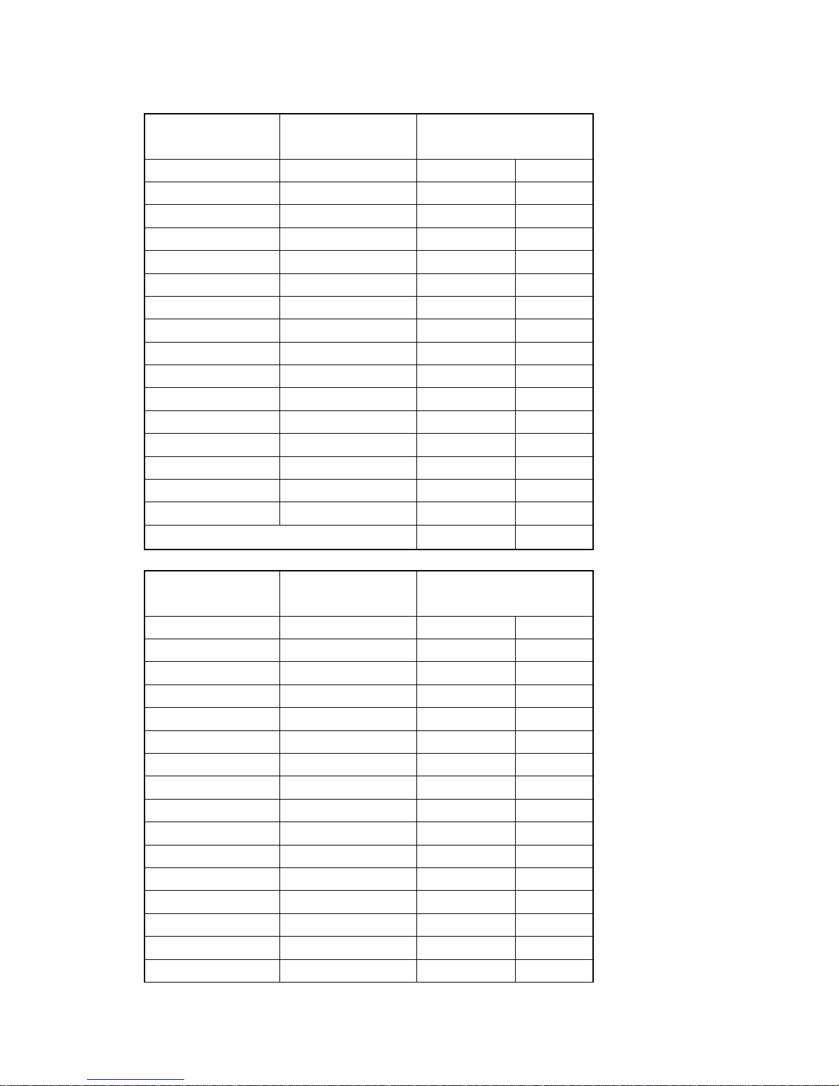
Output powers of transmitters of different power levels (GSM900)
Power Control
level
Output Power
of transmitter
Error
dBm Normal(dB) Limit(dB)
5 33 ±3 ±4
6 31 ±3 ±4
7 29 ±3 ±4
8 27 ±3 ±4
9 25 ±3 ±4
10 23 ±3 ±4
11 21 ±3 ±4
12 19 ±3 ±4
13 17 ±3 ±4
14 15 ±3 ±4
15 13 ±3 ±4
16 11 ±5 ±6
17 9 ±5 ±6
18 7 ±5 ±6
19 5 ±5 ±6
Output powers of transmitters of different power levels (GSM850)
Power Control
level
Output Power
of transmitter
Error
dBm Normal(dB) Limit(dB)
5 33 ±3 ±4
6 31 ±3 ±4
7 29 ±3 ±4
8 27 ±3 ±4
9 25 ±3 ±4
10 23 ±3 ±4
11 21 ±3 ±4
12 19 ±3 ±4
13 17 ±3 ±4
14 15 ±3 ±4
15 13 ±3 ±4
16 11 ±5 ±6
17 9 ±5 ±6
18 7 ±5 ±6
19 5 ±5 ±6
Output powers of transmitters of different power levels (DCS1800)
Power Control
level
Output Power
of transmitter
Error
dBm Normal(dB) Limit(dB)
0 30 ±3 ±4
1 28 ±3 ±4
2 26 ±3 ±4
3 24 ±3 ±4
4 22 ±3 ±4
5 20 ±3 ±4
6 18 ±3 ±4
7 16 ±3 ±4
8 14 ±3 ±4
9 12 ±4 ±5
10 10 ±4 ±5
11 8 ±4 ±5
12 6 ±4 ±5
13 4 ±4 ±5
14 2 ±5 ±6
15 0 ±5 ±6
Output powers of transmitters of different power levels (PCS1900)
Power Control
level
Output Power
of transmitter
Error
dBm Normal(dB) Limit(dB)
0 30 ±3 ±4
1 28 ±3 ±4
2 26 ±3 ±4
3 24 ±3 ±4
4 22 ±3 ±4
5 20 ±3 ±4
6 18 ±3 ±4
7 16 ±3 ±4
8 14 ±3 ±4
9 12 ±4 ±5
10 10 ±4 ±5
11 8 ±4 ±5
12 6 ±4 ±5
13 4 ±4 ±5
14 2 ±5 ±6
15 0 ±5 ±6
4. How the GSM system work:
4.1 General:
The following is a basic introduction to the GSM (Global system for mobile
communication) cellular network. This introduction has been greatly simplified
and cannot describe all the working performances and technologies or
technologies used by the system.
4.2 Introduction of GSM:
Unlike analog cellular systems, GSM use digital wireless technology,
compared with previous analog systems, GSM system has the benefits,:
International roaming: Thanks to international consistency and
standardization, calls can be sent and received in any country supporting
GSM.
Digital air interface: The connection between GSM phones and base station
is fully digital, and furthermore, GSM digitally connects to switching
subsystems and accesses the public switched telephone network.
Security: Calls made over analog system can be listened in with ease using
the appropriate radio receiver. GSM greatly improves security as data is sent
after being digitally encrypted.
Better voice quality: Digital systems are more effective at dealing with same
channel interference, transmission interruption and attenuation. Voice quality
can also be improved through error correction (by rebuilding lost information)
Efficiency: The GSM system can make more efficient use of spectrum
resources than analog system of the past.
In the following diagram, the think line represents the total coverage area of a
hypothetical system. This area is further divided into a number of cells, each of
which includes a cell station (base station), each base station works on a set of
given channels, and connects wireless phone subscribers and the telephone
switching system.
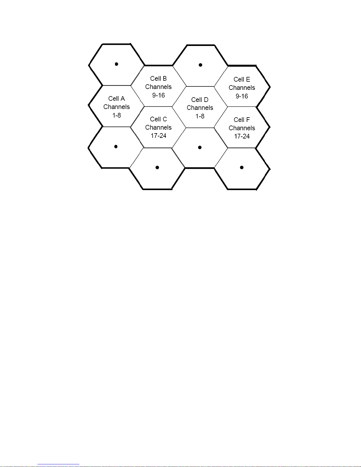
For example, assuming that cell A works in channels 1~8(Numbering is
arbitrary), cell B works in channels 9~16 and cell C works in channels 17~24,
cell D can works in channels 1~8(reusing the channels used by cell A). In this
system, subscribers in cells A and D can use channels 1~8 at the same time.
This means that cells using the same frequencies can be physically closer in a
GSM system than in an analog system, consequently, the advantages of
reusing frequencies become all the more obvious with a GSM system. In
dense subscriber areas, a GSM system can achieve an enhanced traffic
handing rate.
A wireless telephone itself can work on any channel of a system and in this
way, it can work in any cell, because only very low power is necessary for the
communications between a wireless phone and a base station within a specific
cell.
Frequency reuse technology improves the system’s call handling ability
without requiring an increase in the number of channels. However, when the
same frequency is used within a small scope, same-channel interference may
occur. By using digital modulation, forward error correction and load balancing
technology, a GSM system can tolerate more same-channel interference than
analog system.
Through the use of Time Division Multiple Access(TDMA) technology, multiple
calls can share the same carrier. The carrier is divided into continuous TDMA
frame streams. Each frame is divided into 8 time slots. As a connection is

made, the system allocates a dedicated time slot from each TDMA frame, and,
after digitalization, the subscriber data(voice/data) is broken up into blocks.
The subscriber data blocks are sent in the allocated slots of each TDMA frame
in the form of an information pulse.
Utilize Gaussian Minimum Shift keying(GMSK) --- a highly efficient method of
phase modulation, to modulate the data blocks into the carrier.
An information pulse is sent each time and different information pulses may be
sent at different frequencies. This process is referred to as frequency hopping,
Frequency hopping reduces the effect of attenuation and increased the
security of a link. A GSM wireless phone does not need to continuously
transmit but rather only send a pulse in each frame, making the mobile phone
even more power efficient.
Each wireless phone shall be allowed to be moved from one cell to another cell
without causing inconvenience to the subscriber. The mobile phone itself can
measure the signal neighboring cells and quality of a voice channel is
measured together by the mobile phone and base station. Through precise
transfer criteria, transfer should be completed before the subscriber perceives
that the quality of the channel deteriorates.
When a wireless phone is located in the middle of a cell, signal intensity will be
very high. The intensity and quality of the signal will decrease with the
movement of the wireless phone toward the edge of the cell.
Signal information indicates the distance of a subscriber from the base station.
When a wireless phone moves between cells, control is also transferred
among the base station. This type of transfer is carried out by the wireless
phone and the base station and is fully transparent to the subscriber.
5. System overview:
RF part :
RF (Radio Frequency) section is composed of 26MHz crystal, RF main chip,
Saw filter, RF connector, Antenna Switch, RF Amplifier
26MHz Crystal circuit: Mainly comprised of U1102 (Output frequency
26MHz and ±10ppm accuracy) and related RC components.
RF main chip: RF master chip internally integrates RF IC (U1101), Mixer,
U1101 RF
Transceiver
U1102 26MHz
Cr
y
stal
RX SA W : U1 103 ;
DPX:U1104/U1105/U11
06/U1207
U1201 Ante nna Switch + GSM
PA; U1203/U 1204/U1206
/U1206 WCDMA PA
U1202 RF
Connector
VBAT
26MHz
 Loading...