


PMT5287_4G
Disassembly SOP
Model
PMT5287_4G
Station N ame
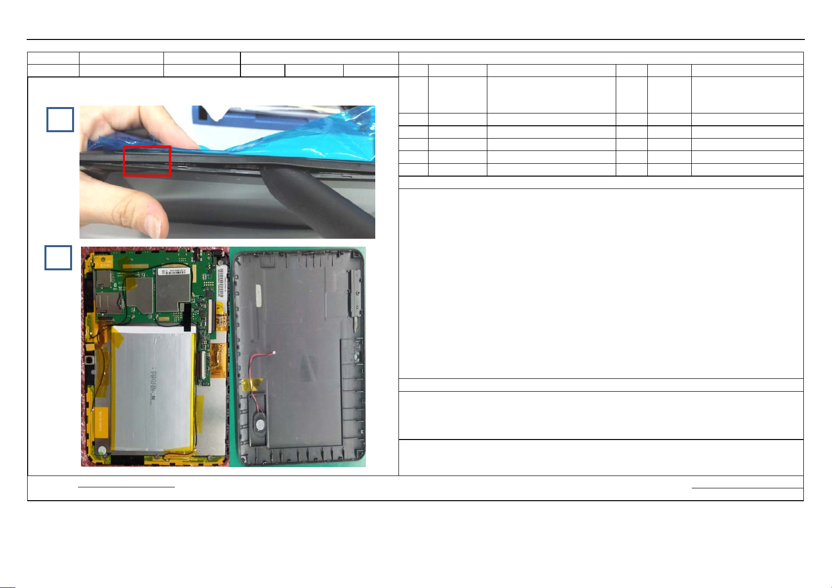
Separating the back cover
BOM required
Station No.
201
Standard Ti me
Page
1/5
No.
Material No.
Description
Qty.
Location
Tools/Equipment
Schematic Diagram Images for reference only
Card for separating the back
of a bank bard)
2
Small knife blade
3
Wrist strap
4
5
6
Steps
1.
Fig. 1, then insert the card with a 120
to separate the front
2.
pry off the speaker cable
3.
NOTES
Record of changes:
Prepared by:
Date: Date:
Fig. 1
Fig. 2
1
Use your fingernail to form a gap between the front cover and the rear cover in the location as illustrated in
~135 degrees of angle between it and the front TP face and keep the angle
cover from the back covers alo ng the edge of the device.
After th e front and back covers are separated, do not take the back cover of f directly; use a pair of tweezers to
socket, then separate the rear cover from the front cover.
The back cover separated from the finished product and the semi-finished products are illustrated in Fig. 2.
cover (same thickness as that
Approved by:
removing
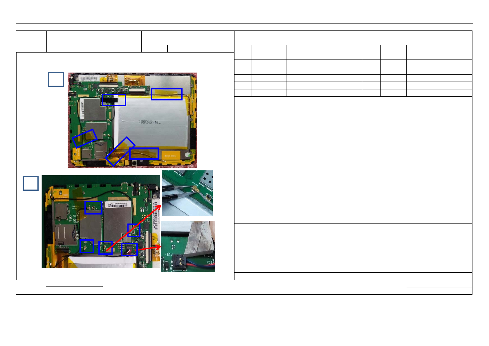
antenna sockets and battery cable socket
Station No.
202
Standard Ti me
Page
2/5
No.
Material No.
Description
Qty.
Location
Tools/Equipment
Schematic Diagram Images for reference only
1
Wrist strap
2
Tweezers
3
Small knife blade
4
5
6
Steps
1.
the cable and cable sockets ; see Fig. 2 after the tape is removed .
2.
3. Insert the small knife blade into a side of the battery cable socket, then pry off the socket (see Fig. 2).
NOTES
Record of changes:
Prepared by:
Date: Date:
Model FL8002 Station Name
Fig. 1
Fig. 2
Removing high-temperature tape/
BOM required
Remove the high-temperature t ape indicated by blue rectangles as illustrated in Fig. 1 ; b e careful not to break
Use a pair of tweezers to clip the antenna socket, then remove it vertically from the PCBA.
Approved by:

cable/motor socket
Station No.
203
Standard Ti me
Page
3/5
No.
Material No.
Description
Qty.
Location
Tools/Equipment
Schematic Diagram Images for reference only
1
Wrist strap
2
Small knife blade
3
Tweezers
4
5
6
Steps
1.
cameras (see Fig. 1)
2. Insert the small knife blade into a side of the cable
3
NOTES
Record of changes:
Prepared by:
Date: Date:
Model FL8002 Station Name
Fig. 1
Fig. 2
Removing camera cable and camera/TP
BOM required
Use your finger to open the camera cable connector and remove t he cable, then remove the front and rear
socket, then pry off the socket (see Fig. 2).
. Use your finger to open the TP cable connector and remove the cable (see Fig. 2)
Approved by:
screen cable
Station No.
204
Standard Ti me
Page
4/5
No.
Material No.
Description
Qty.
Location
Tools/Equipment
Schematic Diagram Images for reference only
1
Wrist strap
0.8±0.1kg)
3
4
5
6
Steps
1.
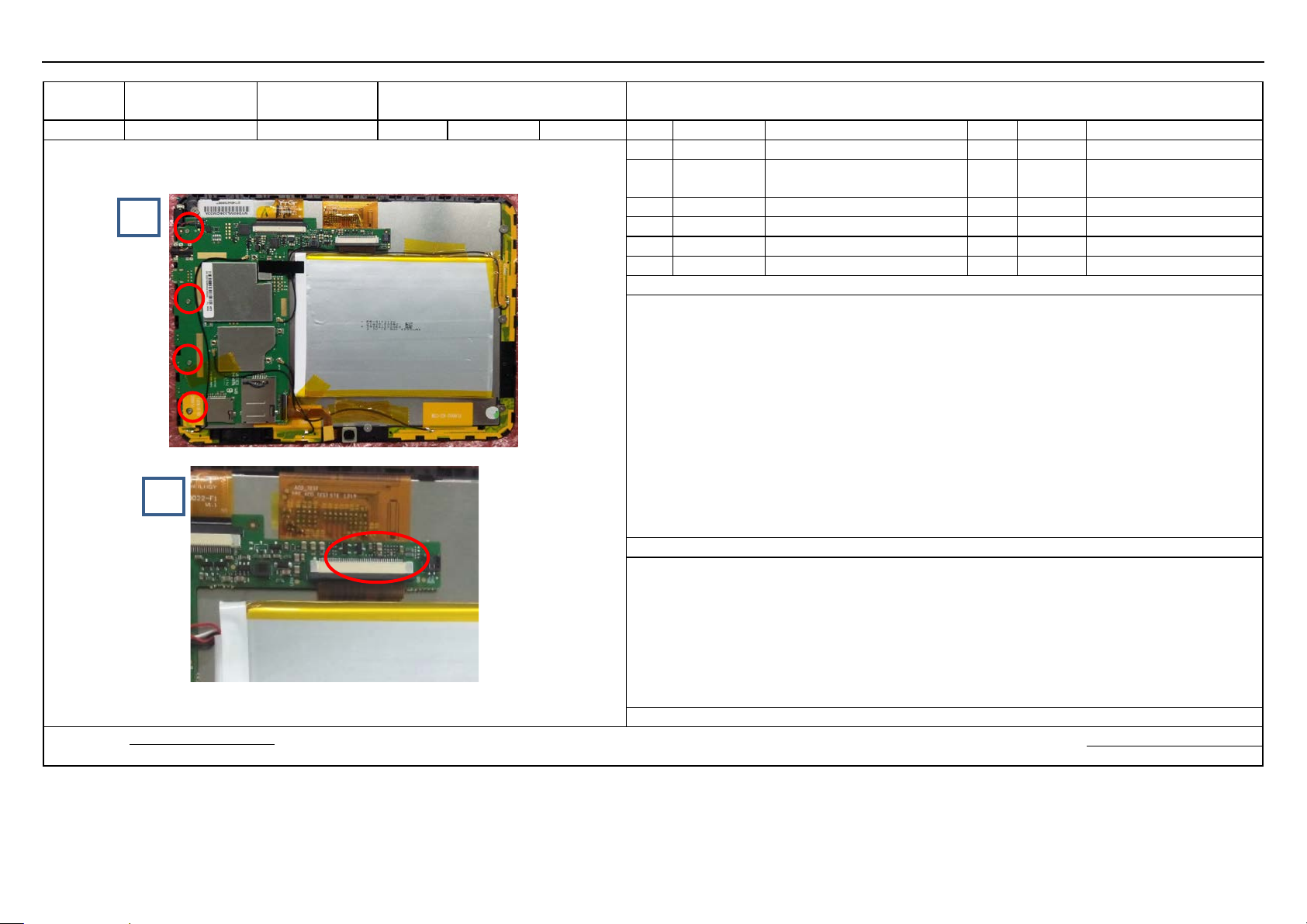
2. Remove the WIFI antenna indicated by the red circle in th e
3
NOTES
Record of changes:
Prepared by:
Date: Date:
Model FL8002 Station Name
Removing motherboard screws / LCD
BOM required
Fig. 1
Fig. 2
2
Use the electric screwdriver to vertically remove the scre ws indicated by the red circles as illustrated in Fig. 1
lower left corner; see Fig. 1
. Open the LCD cable connector, then remove the LCD cable; see Fig. 2
Electric screwdriver (torque:
Approved by:

Model
FL8002
Station N ame
Parts after disassembly
BOM required
Station No.
Standard Ti me
Page
No.
Material No.
Description
Qty.
Location
Tools/Equipment
Schematic Diagram Images for reference only
1
Wrist strap
2
3
4
5
6
Steps
1.
NOTES
Record of changes:
Prepared by:
Date: Date:
Fig. 1
Approved by:
Parts after disassembly (see Fig. 1)
 Loading...