


PMT5287_4G
Assembly SOP

Sticking conductive sponge and WIFI
antenna to motherboard
Station No.
201
Standard Ti me
Page
1/9
No.
Material No.
Description
Qty.
Location
Tools/Equipment
Schematic Diagram Images for reference only
8977 motherboard conductive sponge with
conductive adhesive, material: conductive
15.00mmX3.5mmX1.5mm, manufacturer:
Zhongzhicheng
Conductive
manufacturer: Kexin
3 Front cover assembly
1 Tape cutter
4
5
6
Steps
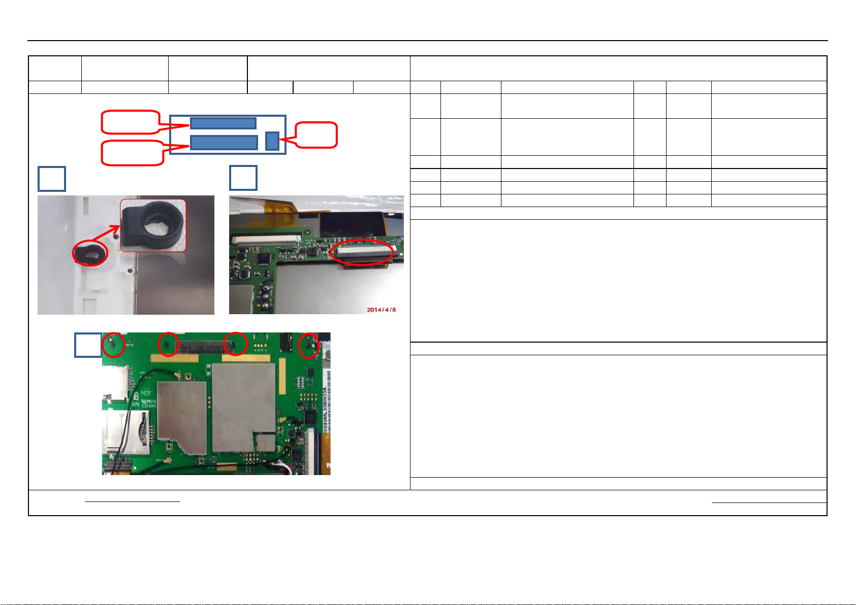
1. Get a motherboard and stick the conductive sponges to the location
Fig. 1
2. Get high
see Fig. 2
3. Stick the GPS antenna to the corresponding location as illustrated in
NOTES
1. When sticking antenna, first press the side of the antenna, then press the antenna stuck to the screen.
Record of changes:
Date: Date:
materials
work table
antenna here
Stick condu c tive sponge
and rubber pad here
Model FL8002 Station Name
tools
Fig. 1
Stick GPS
Fig. 2
1 427000443
2 240000136
-temperature tape and stick it to the solder points on the back of the motherboard to avoid short circuit;
sponge, thickness: 1.50mm,
measurements:
FL8002, GPS antenna, FPC, V0.1,
BOM required
5
sponge
1 antenna High-temperature tape
s indicated by the red ovals as illustrated in
Fig. 3
Wrist strap
Approved by: Prepared by:
Mounting Mic cover, inserting screen cable,
and fixing motherboard
Station No.
202
Standard Ti me
Page
2/9
No.
Material No.
Description
Qty.
Location
Tools/Equipment
Schematic Diagram Images for reference only
Electric screwdriver (torque:
1.0±0.1kgf.cm)
manufacturer: Zhongzhicheng
3 Assembled unit of the front cover
1
4 Processed motherboard
1
5
6
Steps
1.
2. Place the Mic cover in the
3.
see Fig. 2.
4.
5.
NOTES
1.
Record of changes:
Prepared by:
Date: Date:
materials
work table
tools
Model FL8002 Station Name
Fig. 1
Fig. 3
Fig. 2
BOM required
1 412000316 8977 Mic cover, material: rubber 1
FL8002, self-tapping screws ,
2 415000238
Get a Mic cover and check if it is good; if not good, put it in the box for defective ones.
Get a motherboard and insert the screen cable into the connector and place the cable under the motherboard;
Get four screws to fix the motherboard; see Fig. 3.
Self-check if it is OK, if OK, the assembled unit to the next station.
PB1.6*3.0, carbon steel,hardened,
location on the front cover with round chamber up; see Fig. 1.
4 Screw plate
Note that the MIC side with round chamber is up when mounting the MIC cover.
Approved by:
 Loading...