


> www.foxda.com
ProvidingEMSandODMservicestoleadingconsumerelectronicsbrandsworldwide
FoxdaTechnologyIndustrial(SHENZHEN)CO.,Ltd
SOP
ModelName:PMT3277_3G
DocumentContent:AssembleFiles
Version :V1.0
ROHS
t
h
d
Finished Product: ■Pre-processing □Assembly □Test □Packaging SOP
PCBA: □SMT □AI □Component Processing □HI □Test Doc. No.: SOPFW8978001/** Version: A0 FM0761C7
Model FW8978 Station Name
Station No. 101 Standard Time 33s Page 1/5 No. Material No. Description Qty. Location Tools/Equipment
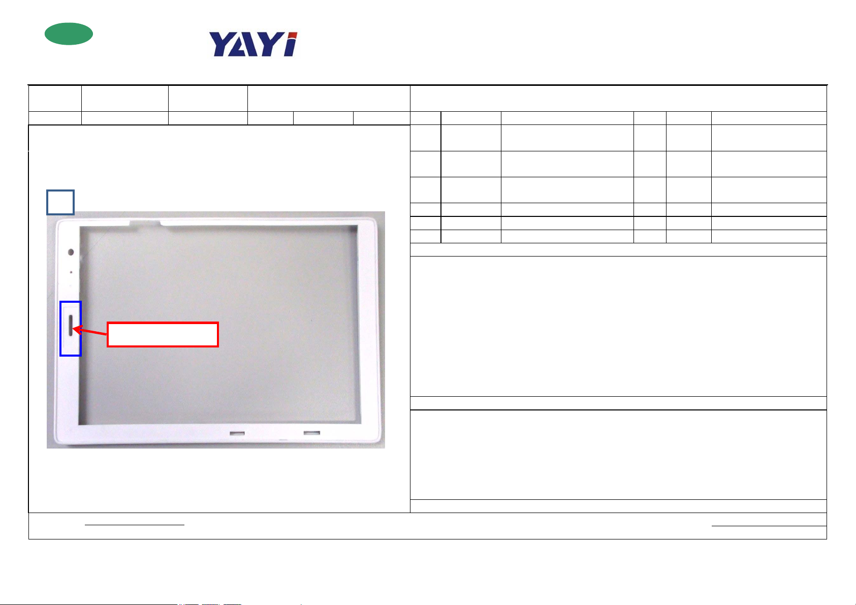
Schematic Diagram 1 421000077
Fig. 1
Location for earpiece mesh
Approved by: Prepared by:
Date: Date:
mounting earpiece mesh/dispensing
adhesive
ACTION ASIA (SHENZHEN) CO., LTD.
Earpiece mesh, 20.8*8mm, 0.1T,
Nylon, Zhongzhicheng
2 401002342
3 61C201010G
4
5
6
1. Get a TP cover (Fig. 1) and check if it is deformed, scratched, and dirty and has burrs, sharp edges, differen
colors and other defects.
2. Get an earpiece mesh and check if its ropes are broken, the mesh holes are blocked by adhesive, the mes
surface is fractured, the adhesive is not sticky, etc.
3. Place the earpiece mesh into the indentation location; the earpiece must be flat and not be outside the
indentation.
4. Place the TP cover with the earpiece mesh on the fixed TP cover jig mounted on the adhesive dispensing
equipment for adhesive and get the jig cover down to fix the TP cover, then start the equipment to dispense
adhesive.
5. Self-check if the adhesive dispensed is uniform and broken; after the earpiece mesh has been mounte
properly, the assembled unit after this process flows to the next station.
1. The TP cover shall not be deformed, scratched, and dirty and have burrs, sharp edges, and different colors. The
earpiece mesh shall not have broken ropes; the mesh holes shall not be blocked by adhesive; the mesh surface shall
not be fractured, etc.; and the earpiece mesh shall be stuck to the inside of the indentation firmly;
2. The adhesive shall be a complete circle and uniform; no fracture or insufficiency of adhesive dispensed shall
occur.
3. Please finish the installation of TP within 2 minutes after the adhesive has been dispensed.
4. Please requisition the materials according to the production order or change order.
Record of changes:
TP cover, FW8978, PC+ABS,
white texture, Zhongzhicheng
GLUE PUR FOR TP AND FRONT
CABINET
BOM required
1 Jigs for dispensing adhesive
1 Wrist strap
0.125g
Steps
NOTES
ROHS
Finished Product: ■Pre-processing □Assembly □Test □Packaging SOP
PCBA: □SMT □AI □Component Processing □HI □Test Doc. No.: SOPFW8978001/** Version: A0 FM0761C7
Model FW8978 Station Name Checking for cleanness and mounting TP BOM required
Station No. 102 Standard Time 65s Page 2/5 No. Material No. Description Qty. Location Tools/Equipment
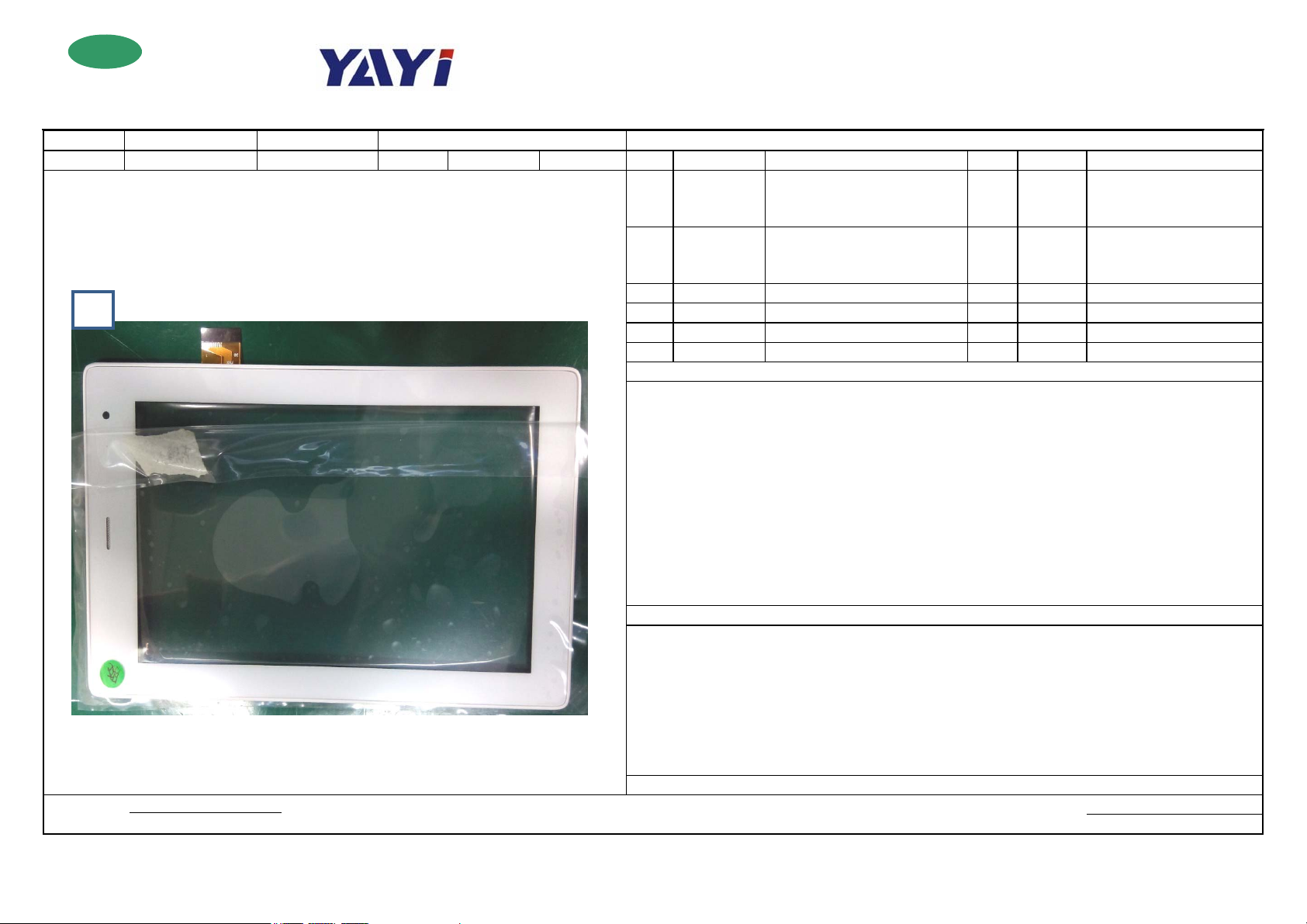
Schematic Diagram 1 251000077
Fig. 1
Approved by: Prepared by:
Date: Date:
ACTION ASIA (SHENZHEN) CO., LTD.
8978, TP, transparent material,
white silkscreen on the bottom,
G+G, 187.4*113.8, 1.4T
8978, TP, transparent material,
2 251000074
3 Dot gauge
4
5
6
1. Get a TP and remove the two protectors (one on the front and one on the back) (if the front has two protectors,
the second layer doesn’t need to be removed); check if the TP is scratched, deformed, and dirty and has different
colors, foreign objects, black and white dots, etc. If it has defects, please use Mara tape to remove dust or dots.
2. Get assembled unit after the previous station, penetrate the TP cable through the TP cover; be careful not to
remove the adhesive on the TP cover; mount the TP slowly by first getting the cable side in place then the
opposite side in place; be careful not to move the TP repeatedly; no excessive adhesive; gently press the surround
of the TP to completely adhesive fix it to the TP cover.
3. Apply the front TP protector removed to the front side of TP; put the back protector on the working table with
the sticky side up
4. Self-check if the TP is in place; the camera aligns with the camera hole; there is excessive adhesive; there are
large gaps; there is deformation; etc. If there are no problems, the assembled unit after this process flows to the
next station.
1. Check if the TP is scratched, deformed, and dirty and has different colors, foreign objects, black & white dots,
etc. If defects exist, use Mara tape to clean, then inspect the TP according to inspection standards. In case of
defective incoming materials, return these materials.
2. When mounting the TP on the TP cover, use uniform force to press and do not move it repeatedly; no
excessive adhesive; the camera aligns with the camera hole; the TP shall not be deformed after being mounted on
the TP cover.
3. Please finish the installation of TP within 2 minutes after the adhesive has been dispensed.
4. Please requisition the materials according to the production order or change order.
Record of changes:
white silkscreen on the bottom,
G+G, 187.4*113.8, 1.4T
1 Wrist strap
1 n-hexane/cleanroom wipers
Steps
NOTES
ROHS
Finished Product: ■Pre-processing □Assembly □Test □Packaging SOP
PCBA: □SMT □AI □Component Processing □HI □Test Doc. No.: SOPFW8978001/** Version: A0 FM0761C7
Model FW8978 Station Name Pressing the TP to the TP cover BOM required
Station No. 103 Standard Time 33s Page 3/5 No. Material No. Description Qty. Location Tools/Equipment
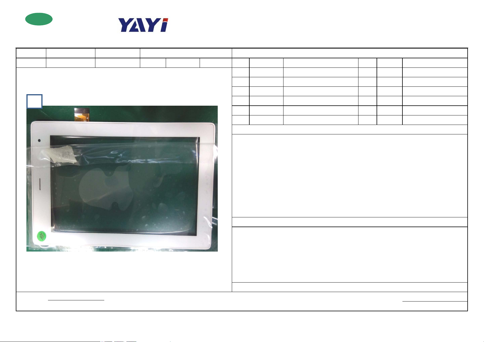
Schematic Diagram 1 Press fit jig
2 Plug gauge
Fig. 1
Approved by: Prepared by:
Date: Date:
ACTION ASIA (SHENZHEN) CO., LTD.
3
4
5
6
Steps
1. Get the assembled unit after the previous station, check if the TP is stuck properly and there should not be
excessive adhesive;
2. Place the assembled unit on the press fit jig equipment, press the two green switches on the equipment at the
same time for 45 seconds. After the press, get the assembled unit out to check the gap between the TP and TP
cover with the plug gauge, the gap shall not be greater than that as set out in the standards (according to QA
inspection standards). Check if the TP is broken or scratched when pressing by equipment;
3. Stick the back protector on the working table to the back of the TP;
4. Self-check if the operations at this station are OK. If OK, place the assembled unit into the plastic crate and let
it stand for two hours before proceeding to the next station.
NOTES
1. The worker at this station can operate two press fit jigs;
2. The TP shall not be broken and scratched during pressing;
3. Use the plug gauge to measure the gap between the TP and TP cover after pressing and the gap shall not be
greater than that as set out in the standards (provided by quality control dept.)
4. Before proceeding to the next station, let the assembled unit stand for 2 hours;
5. Please requisition the materials according to the production order or change order.
Record of changes:
ROHS
Finished Product: ■Pre-processing □Assembly □Test □Packaging SOP
PCBA: □SMT □AI □Component Processing □HI □Test Doc. No.: SOPFW8978001/** Version: A0 FM0761C7
Model FW8978 Station Name
Station No. 104 Standard Time 65s Page 4/5 No. Material No. Description Qty. Location Tools/Equipment
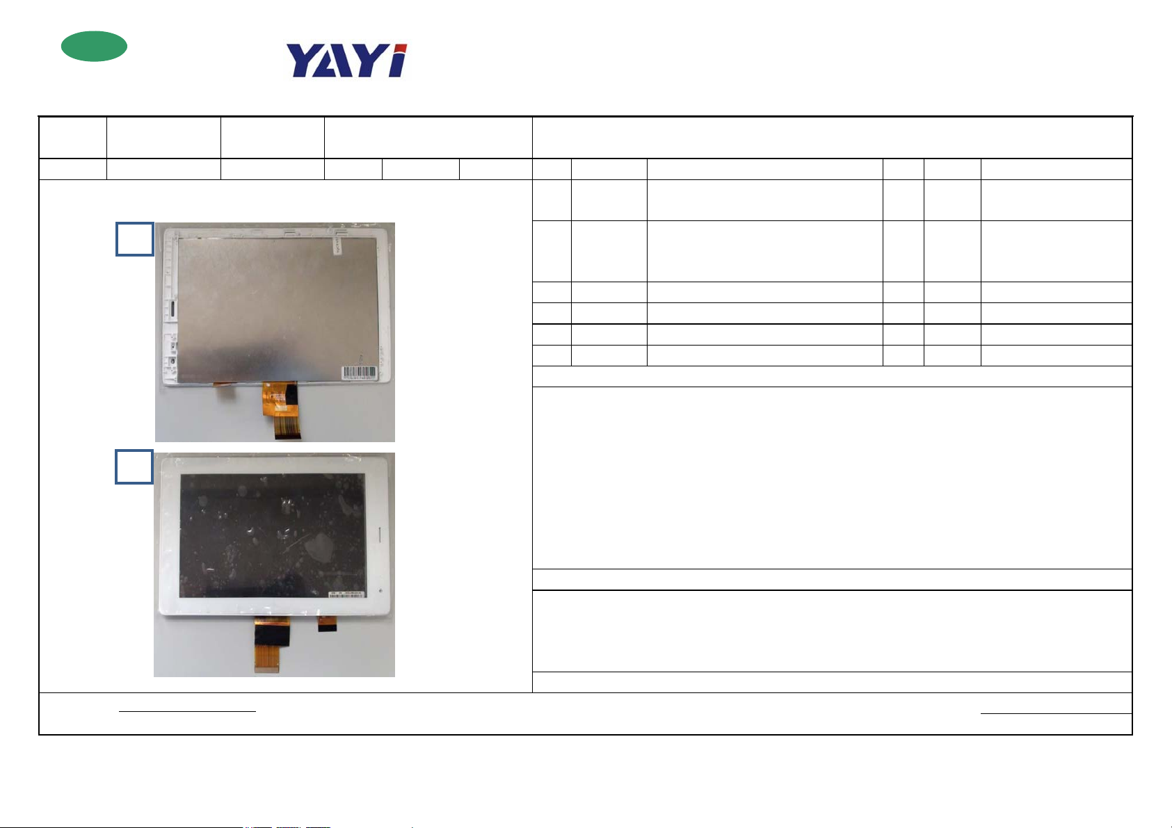
Schematic Diagram 1 250000182
Approved by: Prepared by:
Date: Date:
Fig. 1
Fig. 2
Clean the LCD screen and TP and install
the LCD screen on the TP cover
ACTION ASIA (SHENZHEN) CO., LTD.
BOM required
LCD,CPT
glass,7.0",16:9,1024*600,RD070HD28,Hilevel
display,LCD,7",resolution ratio
2 250000188
3 Plug gauge
4 Dot gauge
5
6
1. Get the assembled unit after the previous station and check if the gap between the TP and TP cover is greater that as
set out in the standards;
2. Remove the protector on the back of the TP and the LCD screen protector; check if the TP and LCD screen are
broken, scratched, and dirty and have dust or dirt, foreign objects inside, etc. In case of excessive dust or dirt, use
cleanroom wipers dipped in a small amount of n-hexane to wipe off most of the dust from the inside out, then use Mara
tape to remove the dust dots;
3. Assemble the cleaned TP and the cleaned LCD screen together, then conduct inspection according to QA inspection
standards;
4. After confirmation of no errors, put it upside down to set aside for flowing to the next station.
1. Clean the LCD screen and TP before installing LCD screen. Make sure the TP and LCD screen are not broken,
scratched, and dirty and have no dust or dirt and foreign objects inside, etc.
2. Please inspect the assembled unit after this process according to QA inspection standards;
3. Please requisition the materials according to the production order or change order.
Record of changes:
1024*600,TFT,IPS,TXDT700CPLA,CPT
glass,TXD
Steps
NOTES
n-hexane/cleanroom wipers
Wrist wrap
 Loading...