

Prestige Pro Line Model Hoods, WMPLDF24241, WMPLDF48241, WMPLDF36241, WMPLDF30241 Installation Instructions Manual
Page 1
INSTALLATION INSTRUCTIONS
Pro Line Model Hoods (PL)
Intended for Domestic Cooking Only
READ AND SAVE THESE INSTRUCTIONS
Installer: Leave this manual with homeowner
Homeowner: Use and Care Information inside
Prestige America - 103 Faireld Rd. Faireld, NJ 07004
Page 2

- Table of Contents -
Important Safety Instructions...................................................1 - 2
Handling Precautions....................................................................2
Packing List for PL 24” Hoods.......................................................3
Important Ventilation Information Before You Begin......................4
Cleaning and Maintenance............................................................5
Planning your Location..............................................................6 - 7
Installation Guide & Wiring Diagram..........................................8 - 9
Installing the Optional Wall Hood Duct Cover...............................10
Warranty Information....................................................................10
PRESTIGE PRODUCTS DIVISION
Signature Marketing Group LTD.
103 Faireld Road
Faireld, NJ 07004
1-800-358-8886
Page 3

IMPORTANT SAFETY INSTRUCTIONS
PRESTIGE HOODS ARE FOR RESIDENTIAL USE ONLY!
CAUTION: FOR GENERAL VENTILATION USE ONLY. DO NOT USE TO
EXHAUST HAZARDOUS OR EXPLOSIVE MATERIALS OR VAPORS
1. Use this unit only in the manner intended by the manufacturer. (If you have questions, contact the
manufacturer at 800-358-8886.
2. Before servicing or cleaning the unit, switch power off at service panel and lock the panel to prevent power from being switched on accidentally. When the service panel cannot be locked, securely
fasten a prominent warning device, such as a tag, to the service panel.
WARNING - TO REDUCE THE RISK OF A RANGE TOP GREASE FIRE:
a) Never leave surface units unattended at high settings, boil overs can cause smoking and may
ignite. Heat oils slowly on low heat.
b) Always turn hood ON when cooking.
c) Clean ventilating lters frequently. DO NOT ALLOW GREASE TO ACCUMULATE ON FAN OR
FILTER.
d) Use proper pan size. Always use cookware appropriate for the size of the surface element.
WARNING - IN THE EVENT OF A RANGE TOP GREASE FIRE, OBSERVE THE FOLLOWING:
a) Smother ames with a close tting lid, cooking sheet, or other metal tray, then turn off the burner.
BE CAREFUL TO PREVENT BURNS. If the ames do not go out immediately, EVACUATE AND
CALL THE FIRE DEPARTMENT.
b) NEVER PICK UP A FLAMING PAN.
c) DO NOT USE WATER, including wet dishcloths or towels - a violent steam explosion may result.
- 1 -
Page 4

d) Use an extinguisher only if:
1) You know you have a class ABC extinguisher and you already know how to operate it.
2) The re is small and contained in the area where it started.
3) The re department is being called.
4) You can ght the re with your back to an exit.
HANDLING PRECAUTIONS
1. Remove all rings, watches, belt buckles, jewelry and any clothing with metal buttons or snaps to
prevent damage to hood.
2. DO NOT REMOVE HOOD FROM ITS ORIGINAL CARTON UNTIL YOU ARE READY TO INSTALL
IT.
3. When you are ready to begin the installation process, remove the hood from its carton and place it
on a clean soft blanket.
4. Inspect the hood carefully for any damage or imperfections before you begin to install the hood. If
any damage or imperfections exist, recarton the hood and call your dealer IMMEDIATELY, do not install
a damaged hood.
5. It is highly recommended that rubber gloves be used to prevent scratches on the hood and to provide
you with a rm grip.
6. When removing the hood from the carton locate the lters. The lters are packed seperately.
DO NOT DISCARD THE PACKAGING
WITHOUT FIRST LOCATING FILTERS!
- 2 -
Page 5

INSPECT ALL MOLDED PACKAGING FOR PARTS BEFORE
DISCARDING. ANY DAMAGE MUST BE REPORTED BEFORE
INST ALLING THE HOOD. ONCE THE HOOD HAS BEEN
INSTALLED, NO RETURN WILL BE ACCEPTED.
Packaging List for Pro Line Hood Series
PL36240, & PL42240 - 36” & 42” Ducted
No blower (Sold and Packaged separately)
Two (2) Stainless Bafe Filters
Two (2) Pre-installed Lights
Remote Blower Starter Collar
Lid for Electrical Box
Manual with Wiring Diagram
PL48240 - 48” Ducted
No Blower (Sold and Packaged separately)
Four (4) Stainless Bafe Filters
Three (3) Pre-installed Lights
Remote Blower Starter Collar
Lid for Electrical Box
Manual with Wiring Diagram
- 3 -
Page 6

IMPORTANT VENTILATION INFORMATION
BEFORE YOU BEGIN
- PL Model hoods can be ducted to the top or rear. Check product guide for additional
transtions, wall caps, and roof caps.
- Duct size for IBPL600 (600 CFM) is 6” round and an optional tranition model TRC8/6
should be used to increase the duct size to 8” round for optimal performance.
- PL4224 and PL4824 require the use of transition model TR6x15/10RD (NOT INCLUDED) when using the IBPL1200 (1200 CFM) blower.
- All PL hoods have a variable speed blower switch. All PL hoods have a light dimmer
switch.
- See remote or in-line blower installation, depending on your installation application,
instructions before you begin.
NOTE TO INSTALLER: Make sure blowers are free from obstructions (packing
and debris). Test run blowers before nalizing installation. Check with manufacturer before attempting to use other than Prestige blower systems. (1-800-3588886 for technical information.)
- 4 -
Page 7

CLEANING & MAINTENANCE
Your hood will not function properly if not cleaned regularly and maintained properly. Clean
the lters regularly, (at least twice a month or every 24 hours of use) by soaking them in
soapy water and rinsing them in the dishwasher at the normal cycle. When the lters are removed, the accessible interior of the hood can be cleaned from grease, using again only soap
and water. Burned out Halogen light bulbs are exchanged in the same way as normal light
bulbs. Make sure to replace them with the same type and wattage. (Replacement bulbs are
Par 16, 60 watt, Halogen 115 volt.)**
Make it a habit to turn on the hood on low speed even when you are boiling water only.
The cleaning of the outside of the hood depends on the material used as a decorative exterior. For stainless steel and powder coated metals. Clean with soap and water only. Do not
use abrasive or aggressive chemicals. Check the outside end of the duct at least once a year.
Make sure that the back-draft-damper hinges are free of grease and move easily. If you have
an insect screen installed in the ductover, make sure that it is not broken or dislocated. Filters
are dishwasher safe or you may hand wash with warm soapy water.
Cleaning & Maintenance
Professional Series Hood
- 5 -
Page 8

PLANNING YOUR LOCATION
Select the proper height to mount the hood. Take into consideration the stature of the person or
persons who will be cooking. A height of 30” to 36” above the cooking surface will suit most users. If
mounted at a height greater than 36” above the cooking surface, the hood should be at least 6” wider
that the cooking appliance to provide proper capture of heat and grease. (Refer to the range manufacturer’s guidelines) Once the proper height is established, draw a level line where the bottom of the
hood will rest. If practical, mount a board equal to the width of the hood along the line so you may
rest the hood on it while installing. Mark a center line on the wall equal to the entire height of the hood
to assist with the proper duct alignment and hood placement. Determine stud location and mark it
clearly. If only one stud can be located, toggle bolts or additional fastening must be installed to rmly
secure the hood to the wall.
Install a 115 volt 15 amp electrical lead in the hole marked on the rough-in diagram. (Fig A)
Example: Location for a 36” hood is 6” from the bottom, 9 1/2” from the centerline.
Verify that the ducting is in the correct location for your application.
Figure A
Centerline
A
B
A B
36” 6” 9 1/2”
42” 6” 11 1/2”
48” 6” 12 1/2”
- 6 -
Page 9

PLANNING YOUR LOCATION
HEIGHT OF THE HOOD
The bottom of the hood should be 30” (76.2 cm) min. to 36” (91.4 cm) max. above the countertop.
This would typically result in the bottom of the hood being 66” (167.6 cm) to 72” (175.3 cm) above
the oor. The bottom of the hood should never be more than 72” (182.9) above the oor or more than
36” (91.4 cm) above the countertop. These dimensions provide for safe and efcient operation of the
hood.
WALL INSTALLATION
Countertop
30” (76.2 cm) Min.
36” (91.4 cm) Max.
66” - 72”
(167.6cm - 182.9 cm)
- 7 -
Page 10

INSTALLATION GUIDE & WIRING DIAGRAM
Installation of Internal Blower Kit (IBPL600 600CFM)
1.) Remove shipping bracket from hood. DO NOT DISCARD SCREWS.
2.) Install blower bracket with the screws removed from the shipping bracket.
3.) Locate the terminal block inside the electrical supply box.
4.) Connect Fan #1 wire (RED) to terminal block #4.
5.) Connect Fan #1 wire (BLACK) to terminal block #6.
6.) Connect the 115 volt supply wire (WHITE) to terminal block #2.
7.) Connect the 115 volt supply wire (BLACK) to terminal block #1.
Installation of Internal Blower Kit (IBPL1200 1200CFM)
1.) Remove shipping bracket from hood. DO NOT DISCARD SCREWS.
FOR FAN # 1
2.) Install blower bracket with the screws removed from the shipping bracket.
3.) Locate the terminal block inside the electrical supply box.
4.) Connect Fan #1 wire (RED) to terminal block #4.
5.) Connect Fan #1 wire (BLACK) to terminal block #6.
6.) Connect the 115 volt supply wire (WHITE) to terminal block #2.
7.) Connect the 115 volt supply wire (BLACK) to terminal block #1.
FOR FAN # 2
8.) Connect Fan # 2 wire (RED) to terminal block #3.
9.) Connect Fan # 2 wire (BLACK) to terminal block #5.
- 8 -
Page 11
INSTALLATION GUIDE & WIRING DIAGRAM
Installation of In-Line or Remote Blower
1.) Locate the terminal block inside the electrical supply box.
2.) Connect Fan #1 wire (RED) to terminal block #4.
3.) Connect Fan #1 wire (BLACK) to terminal block #6.
4.) Connect the 115 volt supply wire (WHITE) to terminal block #2.
5.) Connect the 115 volt supply wire (BLACK) to terminal block #1.
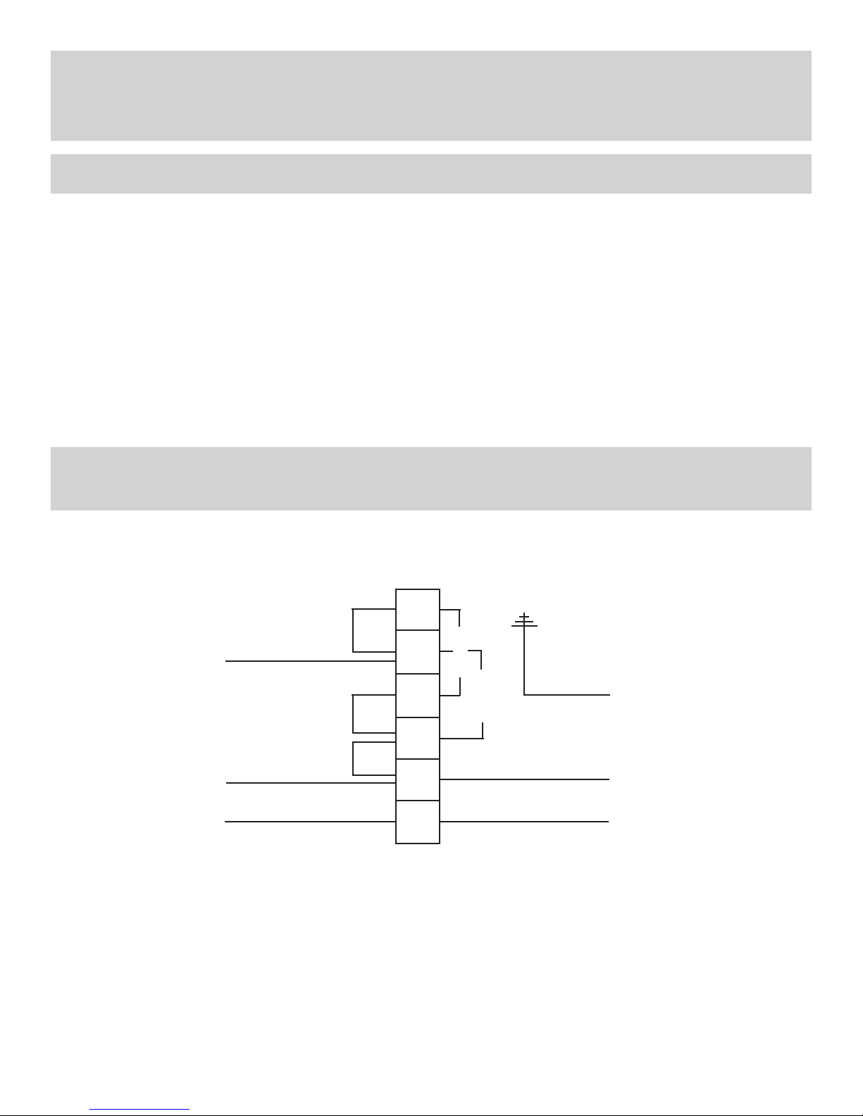
WIRING DIAGRAM
(This wiring diagram is also found on the utility cover.)
RED
HARNESS
PREWIRED
WHITE
BLACK
Connection to Terminal Block
6
5
FAN 1
Ground
4
FAN 2
3
WHITE
2
BLACK
1
Fan 1: 6 +4 Fan 2: 5 + 3
For remote fan use connection for Fan 1.
115 Volt
from Panel
- 9 -
Page 12

INSTALLING THE WALL HOOD DUCT COVER
** Slide the duct cover in place and fasten from inside canopy using sheet metal screws. **
Size of Hood (36, 42, 48, 60)
12”
12”
Duct Cover Illustration
WARRANTY INFORMATION
Prestige Remote Blowers are warranteed to be free from defects in materials and workmanship,
under normal household use for a period of :
ONE (1) YEAR
Prestige will warranty all parts and related labor to replace them, during the one (1) year warranty
period. This applies to the actual parts and normal labor and excludes all other costs, removal and
re-installation. Items NOT covered in the warranty include: light bulbs, items fabricated to customer
design, consequential damage, removal & reinstallation, abnormal travel outside the service area, including but not limited to: remote area transport, ferries, or excessive mileage. If any of these situations
apply, the customer will be responsible for payment in full of said exclusion.
The main motor is warranteed for a period of :
Prestige will replace any motor that fails within the
ve (5) year warranty, free of charge, on product when
it is located within the United States. This applies
only to the motor itself and excludes all other costs,
including labor, removal and re-installation.
This warranty does not apply to damage resulting from commercial use, abuse, accident,
natural disasters or electrical surge to the unit.
Prestige will not be responsible for consequential damages.
FIVE (5) YEARS
- 10 -
Page 13

 Loading...