

Page 1

Instructions for use
Installation advice
DUAL
FUEL
DOUBLE
OVEN
COOKER
PR 100 DODF
Before operating this cooker,
please read these instructions carefully
KEEP IN A SAFE PLACE
GB
Page 2

2
Dear Customer,
Thank you for purchasing a Prestige Dual Fuel Double Oven
Cooker.
The safety precautions and recommendations in these instructions
are for your own safety and that of others. They will also provide a
means by which to make full use of the features offered by your
appliance.
Please keep this booklet in a safe place. It may be useful in the
future, either to yourself or to others in the event that doubts
should arise relating to its operation.
This appliance must be used only for its intended purpose , that
is for the domestic cooking of foodstuffs. Any other form of usage
is to be considered as inappropriate and therefore dangerous.
The manufacturer declines all responsibility in the event of
damage caused by improper, incorrect or illogical use of the
appliance.
This cooker has been designed, constructed and marketed in compliance with:
- safety requirements of EEC Directive “Gas” 90/396;
- safety requirements of EEC Directive “Low voltage” 73/23;
- protection requirements of EEC Directive “EMC” 89/336;
- requirements of EEC Directive 93/68.
Important:
This appliance is designed and
manufactured solely for the cooking
of domestic (household) food and is
not suitable for any non domestic
application and therefore should not
be used in a commercial environment.
The appliance guarantee will be
void if the appliance is used within
a non domestic environment i.e. a
semi commercial, commercial or
communal environment.
FIRST USE OF THE OVEN
Follow the instructions below:
– Furnish the interior of the oven by
placing the wire racks as described in
“Cleaning and maintenance”.
– Insert shelves and tray.
– Switch the empty oven on to max to
eliminate grease from the heating ele-
ments.
– Let the oven cool down and clean the
interior of the oven with a cloth
soaked in water and neutral deter-
gent, then dry carefully.
Page 3

3
IMPORTANT SAFEGUARDS
AND RECOMMENDATIONS
After unpacking the appliance, check to
ensure that it is not damaged and that
the oven door closes correctly. If in
doubt, do not use and consult your supplier or a professionally qualified technician.
Packing materials (i.e. plastic bags,
polystyrene foam, nails, packing straps,
etc.) should not be left around within
easy reach of children, as these may
cause serious injuries.
● ATTENTION: please peel plastic
cover off both sides and front of
the oven before use.
● Do not attempt to modify the technical
characteristics of the appliance as
this may cause danger to users.
● Do not carry out any cleaning or
maintenance operations on the appliance without first disconnecting it
from the electric power supply.
● If you should decide not to use this
appliance any longer (or decide to
substitute an older model), before disposing of it, it is recommended that it
is made inoperative in an appropriate
manner in accordance to health and
environmental protection regulations,
ensuring in particular that all potentially hazardous parts be made harmless, especially in relation to children
who could play with unused appliances.
● After use, always ensure that the con-
trol knobs are in the off position.
● Do not allow young children or infirm
persons to use the appliance without
your supervision.
● During and after use of the cooker,
certain parts will become very hot. Do
not touch hot parts.
● Keep children away from the cooker
when it is in use.
● Some appliances are supplied with a
protective film on steel and aluminium
parts. This film must be removed
before using the appliance.
● Fire risk! Do not store flammable
material in the oven or in the storage
compartment.
● Make sure that electrical cords con-
necting other appliances in the proximity of the cooker cannot come into
contact with the hob or become
entrapped in the oven door.
● Do not line the oven walls with alu-
minium foil. Do not place baking trays
or the drip tray on the base of the
oven chamber.
● The manufacturer declines all liability
for injury to persons or damage to
property caused by incorrect or
improper use of the appliance.
● The various components of the appli-
ance are recyclable. Dispose of them
in accordance with the regulations in
force in your country. If the appliance
is to be scrapped, remove the power
cord.
● Always use oven gloves when remov-
ing the shelves and food trays from
the oven whilst hot.
● Do not hang towels, dishcloths or
other items on the cooker or its handle – as this could be a fire hazard.
● Clean the oven regularly and do not
allow fat or oils to build up in the oven
base or trays. Remove spillages as
soon as they occur.
● Do not stand on the cooker or on the
open oven door.
● Always stand back from the cooker
when opening the oven door to allow
steam and hot air to escape before
removing the food.
● This appliance is for domestic use
only.
Page 4
4
Note:
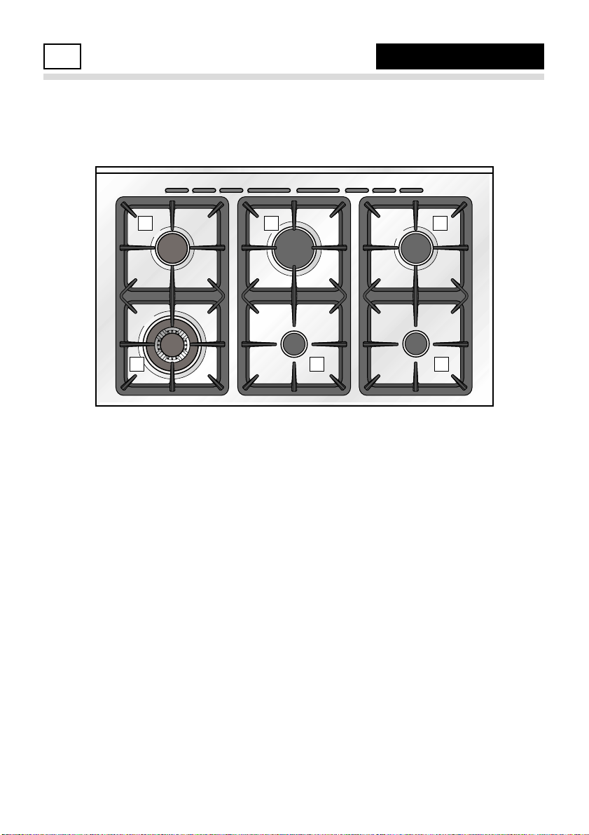
✓ The electric ignition is incorporated in the knobs.
COOKING HOB
1
Fig. 1.1
COOKING HOB
1. Auxiliary burner (A) 1,00 kW
2. Semi-rapid burner (SR) 1,75 kW
3. Rapid burner (R) 3,00 kW
4. Triple-ring burner (TR) 3,50 kW
114
2 3 2
Page 5
5
Fig. 2.1
A
U
T
O
98 65
3
217
4
12
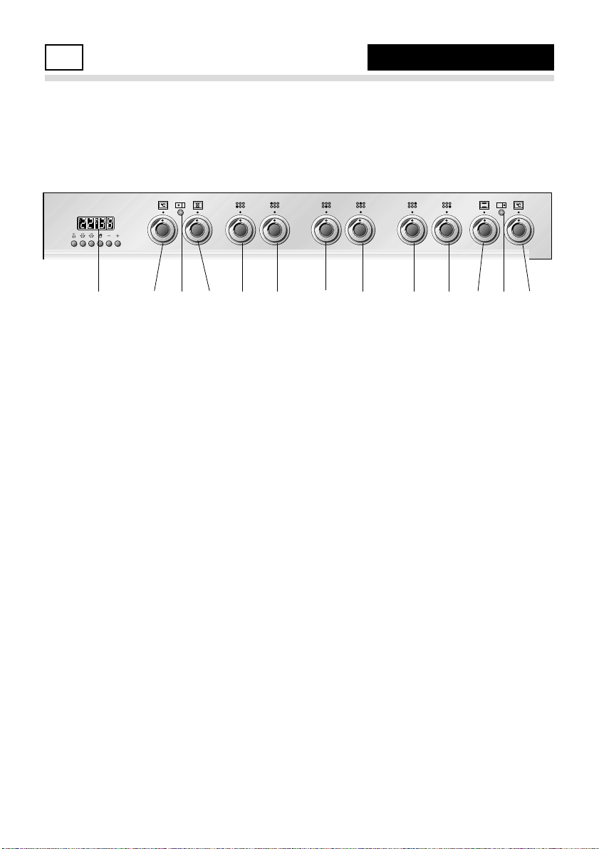
CONTROL PANEL - Controls description
1. Front right burner control knob
2. Rear right burner control knob
3. Rear central burner control knob
4. Front central burner control knob
5. Rear left burner control knob
6. Front left burner control knob
7. Multifunction main oven switch knob
8. Multifunction main oven temperature knob
9. Electronic programmer (Main oven only)
10. Conventional oven temperature knob
11. Conventional oven switch knob
Pilot lamps:
12. Main oven temperature indicator light
13. Conventional oven temperature indicator light
11 1013
NB: Your appliance has been fitted with a cooling fan to achieve optimum efficiency of
the controls and to ensure lower surface temperatures are maintained.
The cooling fan is thermostatically controlled and will operate when the oven is turned on
and will continue to be heard running for a short period of time until the oven cavity has
cooled down to a predetermined level.
CONTROL PANEL2
Page 6
6
Fig. 3.1
Fig. 3.2
LIGHTING THE BURNERS
To ignite the burner:
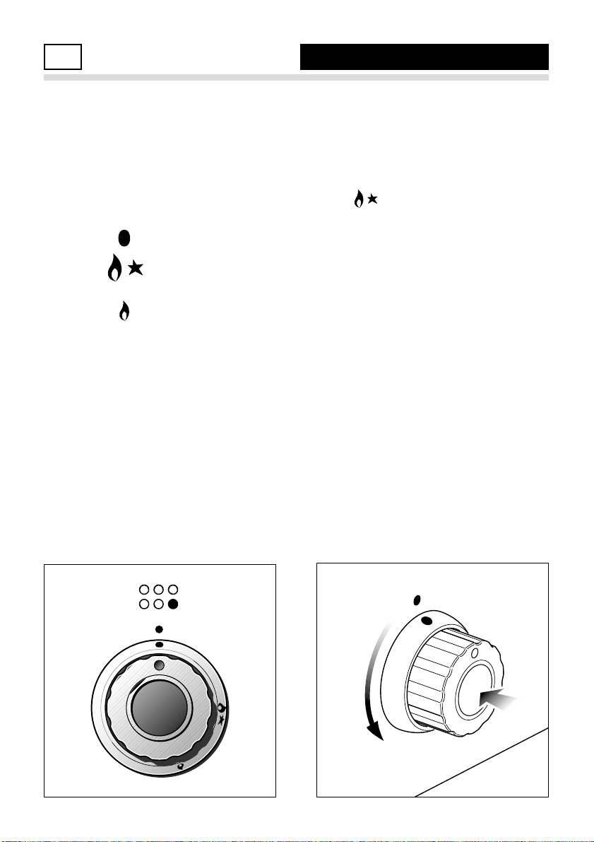
1) Lightly press and turn the knob anticlockwise and position the knob symbol to the indicator printed on the
control panel (fig. 3.2).
2) Press the knob to operate the electric
ignition; or, in the case of a mains failure light the burner with a match or
lighted taper.
3) Adjust the burner according to the setting required.
GAS BURNERS
Each burner is controlled by a gas tap
assuring the opening and the closing of
the gas supply.
Make the lever of the knob match with
the indicator on the control panel to
obtain:
– symbol : off
– symbol :
full on (nominal rate)
– symbol : reduced rate
To reduce the gas flow to minimum,
rotate the knob anti-clockwise to point
the lever towards the small flame symbol.
The maximum aperture position permits
rapid boiling of liquids, whereas the minimum aperture position allows slower
warming of food or maintaining boiling
conditions of liquids (simmering).
Other intermediate operating adjustments can be achieved by positioning
the lever between the maximum and
minimum aperture positions, and never
between the maximum aperture and off
positions.
ATTENTION: the cooking hob becomes
very hot during operation.
Keep children away.
USE OF COOKING HOB
3
Page 7
7
CHOICE OF THE BURNER
On the control panel, near every knob,
there is a diagram that indicates which
burner is controlled by that knob.
The suitable burner must be chosen
according to the diameter and the
capacity used.
As an indication, the burners and the
pots must be used in the following way:
BURNERS POT DIAMETER
Auxiliary 12 - 14 cm
Semi-rapid 16 - 24 cm
Rapid 24 - 24 cm
Triple-ring 26 - 28 cm
Wok
(*)
max 36 cm
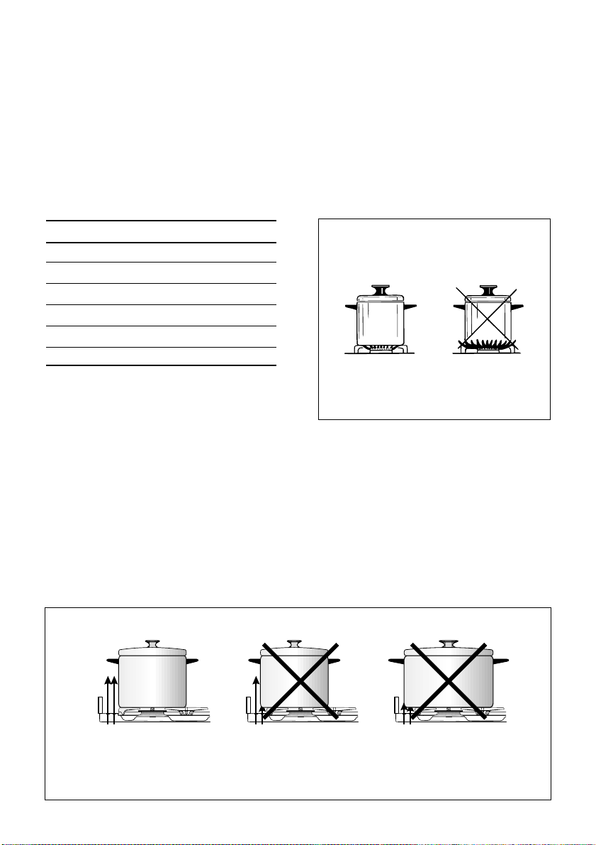
do not use pans with concave or convex bases
(*): wok pans have to be used only with the spe-
cial grille fitted ( see “correct use of triple-ring
burner”).
Fig. 3.3
It is important that the base diameter of
the pot is at least the same diameter as
the burner ring to obtain an efficient heat
transfer.
Always position pans centrally over the
burners.
Adjust the size of the flame so that it
does not lick up the side of the pan.
Position pan handles so that they
cannot be accidentally knocked.
CORRECT USE OF RAPID BURNER
Fig. 3.4
(cooling fan)
AIR FLOW
AIR FLOW
(cooling fan)
AIR FLOW
(cooling fan)
Page 8
8
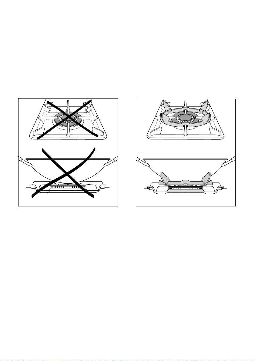
CORRECT USE OF TRIPLE-RING BURNER (Fig. 3.5a - 3.5b)
Flat-bottomed pans should be placed directly onto the pan-support.
When using a WOK always place the supplied stand in position over the burner to main-
tain the correct operation of the triple-ring burner (Fig. 3.5a - 3.5b).
IMPORTANT:
The special grille for wok pans (fig. 3.5b) MUST BE PLACED ONLY over the pan-rest for
the triple-ring burner.
Fig. 3.5b
Fig. 3.5a
WRONG
CORRECT
Page 9

9
Attention: the oven door becomes
very hot during operation.
Keep children away.
GENERAL FEATURES
The multi- function oven can be programmed for 7 different functions to satisfy every cooking need.
The 7 positions are thermostatically controlled and are obtained by a combination of 4 heating elements which are:
– Bottom element 1400 W
– Top element 1000 W
– Grill element 2000 W
– Circular element 2500 W
NOTE:
Upon first use, it is advisable to operate the
oven for 30 minutes in the position and
for another 15 minutes at maximum (temperature knob on position 250°C) in the
positions
and
, to eliminate possible
traces of grease on the heating elements.
Clean the oven and accessories with warm
water and washing-up liquid.
WARNING:
The door is hot, use the handle.
OPERATING PRINCIPLES
Heating and cooking in the MULTIFUNCTION oven are obtained in the following ways:
a. by normal convection
The heat is produced by the upper and
lower heating elements.
b. by forced convection
The circular heating element and fan
constantly circulate heated air over the
food in the oven for a more rapid and
even cooking process. It is possible to
cook several dishes simultaneously.
c. by semi-forced convection
The heat produced by the upper and
lower heating elements is distributed
throughout the oven by the fan.
d. by radiation
The heat is irradiated by the infra red
grill element.
e. by radiation and ventilation
The irradiated heat from the infra red
grill element is distributed throughout
the oven by the fan.
f. by ventilation
The food is defrosted by using the fan
only function without heat.
MULTI-FUNCTION MAIN OVEN
4
LEFT OVEN
Page 10
10
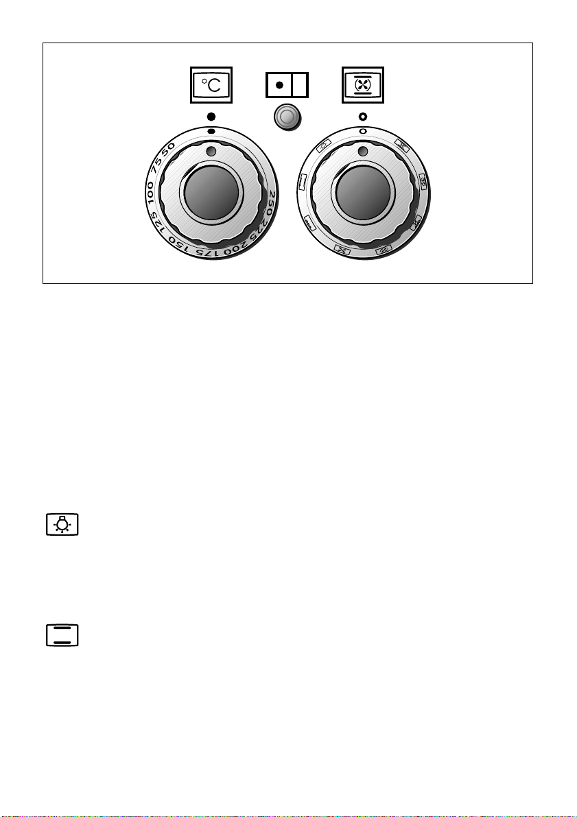
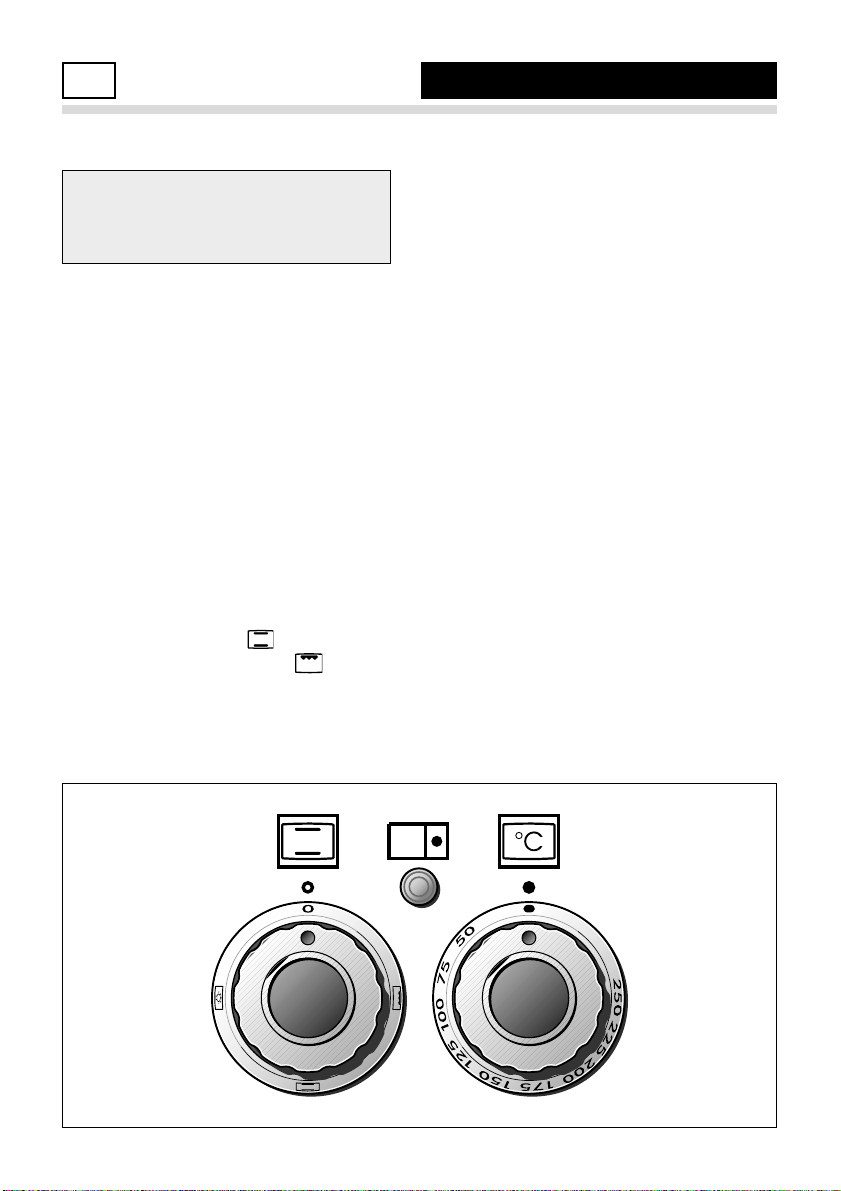
FUNCTION SELECTOR KNOB (fig. 4.2)
Rotate the knob clockwise to set the oven for one of the following functions:
TEMPERATURE KNOB (fig.4.1)
To turn on the heating elements of the oven, set the switch knob on the desired program
and select the required temperature.
To set the temperature, line up the required temperature with the control panel indicator.
The light above the function selector will illuminate when the oven is switched on and
turns off when the oven reaches the correct temperature. The light will cycle on and off
during cooking in line with the oven temperature.
Fig. 4.1 Fig. 4.2
OVEN LIGHT
By setting the knob to this position, only the oven light comes on (15 W).
The light remains on whilst any of the cooking modes are selected.
TRADITIONAL CONVECTION COOKING
The upper and lower heating elements are switched on. The heat is diffused by natural
convection and the temperature must be set between 50° C and 250° C.
It is necessary to preheat the oven before adding the foods to be cooked.
Recommended for:
For foods which require the same cooking temperature both internally and externally, i.
e. roasts, spare ribs, meringue, etc.
Page 11
11
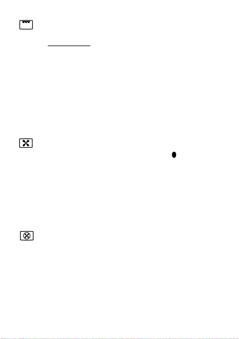
GRILLING
The infra-red heating element is switched on. The heat is diffused by radiation.
Use with the oven door closed
and the temperature knob between 50° and 225°C for 15
minutes, then to position 175°C.
Note: It is recommended that you do not grill for longer than 30 minutes at any one
time.
Attention: the oven door becomes very hot during operation. Keep children away.
For correct use see “USE OF THE GRILL”
Recommended for:
Intense grilling action for cooking with a broiler; browning, crisping, “au gratin”, toasting, etc.
HOT AIR COOKING
The circular element and the fan are on. The heat is diffused by forced convection and
the temperature must be set between 50° and 250 °C.
It is not necessary to preheat the oven.
Recommended for:
For foods that must be well done on the outside and tender or rare on the inside, i. e.
lasagna, lamb, roast beef, whole fish, etc.
DEFROSTING FROZEN FOODS
Only the oven fan is on. To be used with the temperature knob on “ ” because the other
positions will have no effect. The defrosting is done by simple ventilation without heat.
Recommended for:
To rapidly defrost frozen foods; 1 kilogram requires about one hour.
The defrosting times vary according to the quantity and type of foods to be defrosted.
Page 12
12
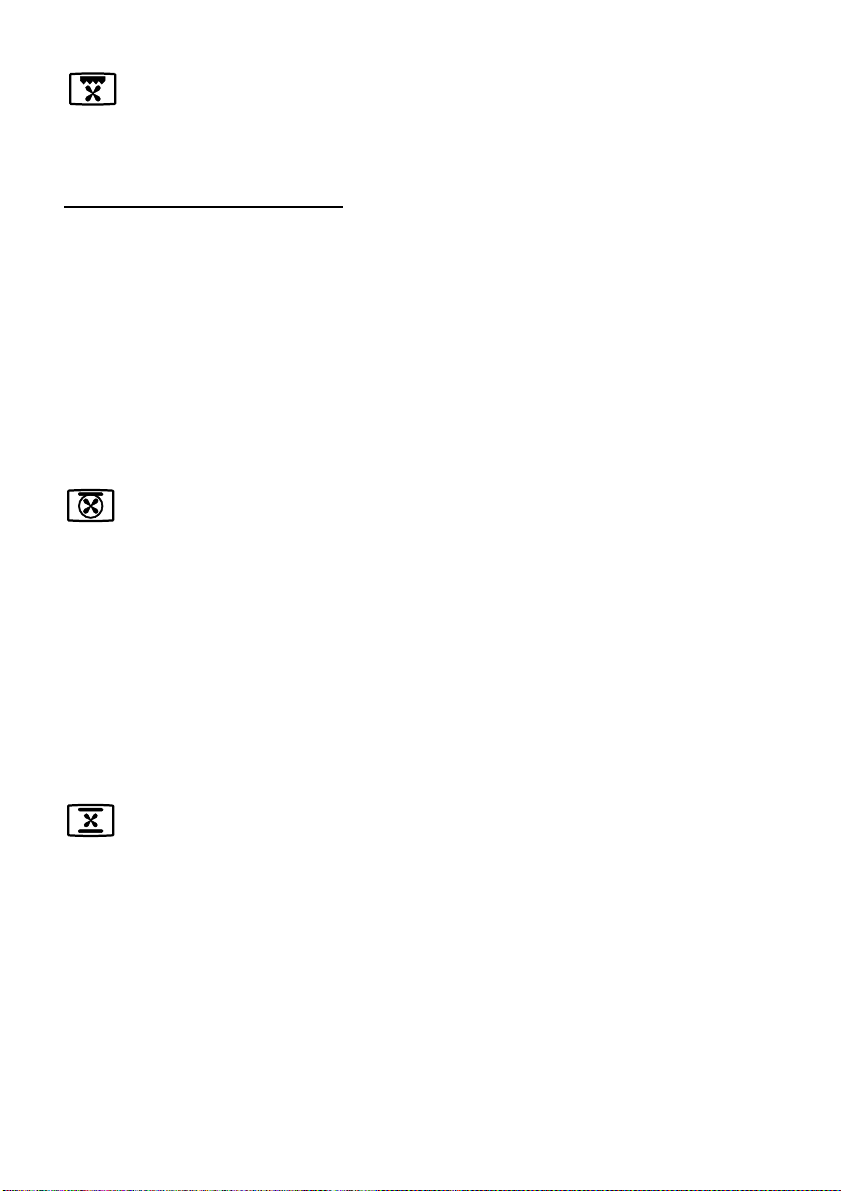
THAWING AND WARMING UP
The upper element and the circular element connected in series, are switched on; also the fan
is on. The heat is diffused by forced convection with the most heat being produced by the
upper element.
The temperature must be set between 50° and 140 °C.
Recommended for:
To keep foods hot after cooking. To slowly heat already cooked foods.
VENTILATED GRILL COOKING
The infra-red ray grill and the fan are on. The heat is mainly diffused by radiation and the fan
then distributes it throughout the oven. The temperature must be set between 50° and
175 °C for max 30 minutes. It is necessary to preheat the oven for about 5 minutes.
Use with the oven door closed.
Attention: the oven door becomes very hot during operation.
Keep children away.
For correct use see “GRILLING AND “AU GRATIN”.
Recommended for:
For grill cooking when a fast outside browning is necessary to keep the juices in, i. e. veal
steak, steak, hamburger, etc.
CONVECTION COOKING WITH VENTILATION
The upper and lower heating elements and the fan turn on.
The heat coming from the top and bottom is diffused by forced convection.
The temperature must be set between 50° and 250 °C.
Recommended for:
For foods of large volume and quantity which require the same internal and external
degree of cooking; for ie: rolled roasts, turkey, legs, cakes, etc.
Page 13

13
USE OF THE GRILL
Preheat the oven for about 5 minutes.
Introduce the food to be cooked, posi-
tioning the rack as close to the grill as
possible.
The drip tray should be placed under the
rack to catch the cooking juices and fats.
Grill with the oven door closed.
Do not grill for longer than 30 minutes
at any one time (Grilling for longer
than the reccomended time may mean
the appliance overheats).
CAUTION: the oven door becomes
very hot during operation. Keep
children well out of reach.
COOKING ADVICE
OVEN COOKING
Before introducing the food, preheat the
oven to the desired temperature.
For a correct preheating operation, it is
advisable to remove the tray from the
oven and introduce it together with the
food, when the oven has reached the
desired temperature.
ROASTING
To obtain classical roasting, it is necessary to remember:
– that it is advisable to maintain a tem-
perature between 180 and 200 °C.
– that the cooking time depends on the
quantity and the type of foods.
SIMULTANEOUS COOKING OF
DIFFERENT FOODS
The MULTI-FUNCTION oven set on
position
and
gives simultaneous
cooking of different foods.
Different foods such as fish, cake and
meat can be cooked together without
mixing the smells and flavours.
This is possible since the fats and vapors
are oxidized while passing through the
electrical element and therefore are not
deposited onto the foods.
The only precautions to follow are:
– The cooking temperatures of the
different foods must be as close to as
possible, with a maximum difference of
20° - 25 °C.
– The introduction of the different dishes
in the oven must be done at different
times in relation to the cooking times of
each one.
This type of cooking saves time and
energy.
GRILLING AND “AU GRATIN”
Set the switch to position .
Set the temperature knob to 175 °C and
after having preheated the oven, simply
place the food on the shelf.
Close the door and let the oven operate
until grilling is complete.
Adding a few dabs of butter before the end
of the cooking time gives the golden “au
gratin” effect.
Note: It is recommended that you do not
grill for longer than 30 minutes at any
one time.
ATTENTION: the oven door becomes
very hot during operation.
Keep children away.
Page 14
14
Attention: the oven door becomes
very hot during operation.
Keep children away.
GENERAL FEATURES
As its name indicates, this is an oven
that presents particular features from an
operational point of view.
The conventional oven is provided with 3
heating elements which are:
– Top element 700 W
– Bottom element 800 W
– Grill element 1450 W
NOTE:
Upon first use, it is advisable to operate
the oven at the maximum temperature
(thermostat knob on position 250) for 60
minutes in the position and for another 15 minutes in the position to eliminate possible traces of grease on the
heating elements.
OPERATING PRINCIPLES
Heating and cooking in the CONVENTIONAL oven are obtained in the following ways:
a. by natural convection
The heat is produced by the upper
and lower heating elements.
b. by radiation
The heat is radiated by the infra red
grill element.
CONVENTIONAL OVEN
5
RIGHT OVEN
Fig. 5.1 Fig. 5.2
This oven is equipped with a special
dish rack: you can use your conventional oven to warm the plates (at about
60°C) before serving dinner.
For correct use see “TRADITIONAL
CONVECTION COOKING OR WARMING PLATES” and “USE OF SPECIAL
DISH RACK”.
WARNING:
The door is hot, use the handle.
Page 15

15
TRADITIONAL CONVECTION COOKING OR WARMING PLATES
TRADITIONAL CONVECTION COOKING
This function can also be used for traditional convection cooking: the temperature knob
must be regulated between 50 and 250°C. It is necessary to preheat the oven before
introducing the foods to be cooked.
Traditional convection cooking recommended use:
For foods which require the same cooking temperature both internally and externally, i.e.
roasts, spare ribs, meringue, etc.
WARMING PLATES
The upper and lower heating elements are switched on; the heat is diffused by natural
convection. The temperature knob must be set to about 60°C.
Warming plates recommended use:
Dish warming using the special rack. For correct use see the chapter “USE OF SPECIAL
DISH RACK”.
FUNCTION SELECTOR KNOB (fig. 5.1)
Rotate the knob clockwise to set the oven for one of the following functions.
TEMPERATURE KNOB (Fig. 5.2)
This only sets the cooking temperature and does not switch the oven on.
Rotate clockwise until the required temperature is reached (from 50 to 250°C).
The light above the function selector will illuminate when the oven is switched on and
turns off when the oven reaches the correct temperature. The light will cycle on and off
during cooking in line with the oven temperature.
OVEN LIGHT
By setting the knob to this position, only the oven light comes on (15 W).
It remains on in all the cooking modes.
Page 16

16
USE OF THE GRILL
Preheat the oven for about 5 minutes.
Introduce the food to be cooked,
positioning the rack as close to the grill
as possible.
The drip pan should be placed under the
rack to catch the cooking juices and fats.
Grill with the oven door closed.
Do not grill for longer than 30 minutes
at any one time
(Grilling for longer
than the reccomended time may mean
the appliance overheats).
Caution: the oven door becomes very
hot during operation. Keep children
well out of reach.
OVEN COOKING
Before introducing the food, preheat the
oven to the desired temperature.
For a correct preheating operation, it is
advisable to remove the tray from the
oven and introduce it together with the
food, when the oven has reached the
desired temperature.
Check the cooking time and turn off the
oven 5 minutes before the theoretical
time to recuperate the stored heat.
GRILLING
The infra-red heating element is switched on. The heat is diffused by radiation.
Use with the oven door closed, the function knob set to , and the temperature knob
between 50° and 225°C for 15 minutes, then to position 175°C.
For cooking hints, see the chapter “USE OF THE GRILL”.
Recommended use:
Intense grilling, browning, cooking au gratin and toasting etc.
It is recommended that you do not grill for longer than 30 minutes at any one time.
Attention: the oven door becomes very hot during operation.
Keep children away.
Page 17
17
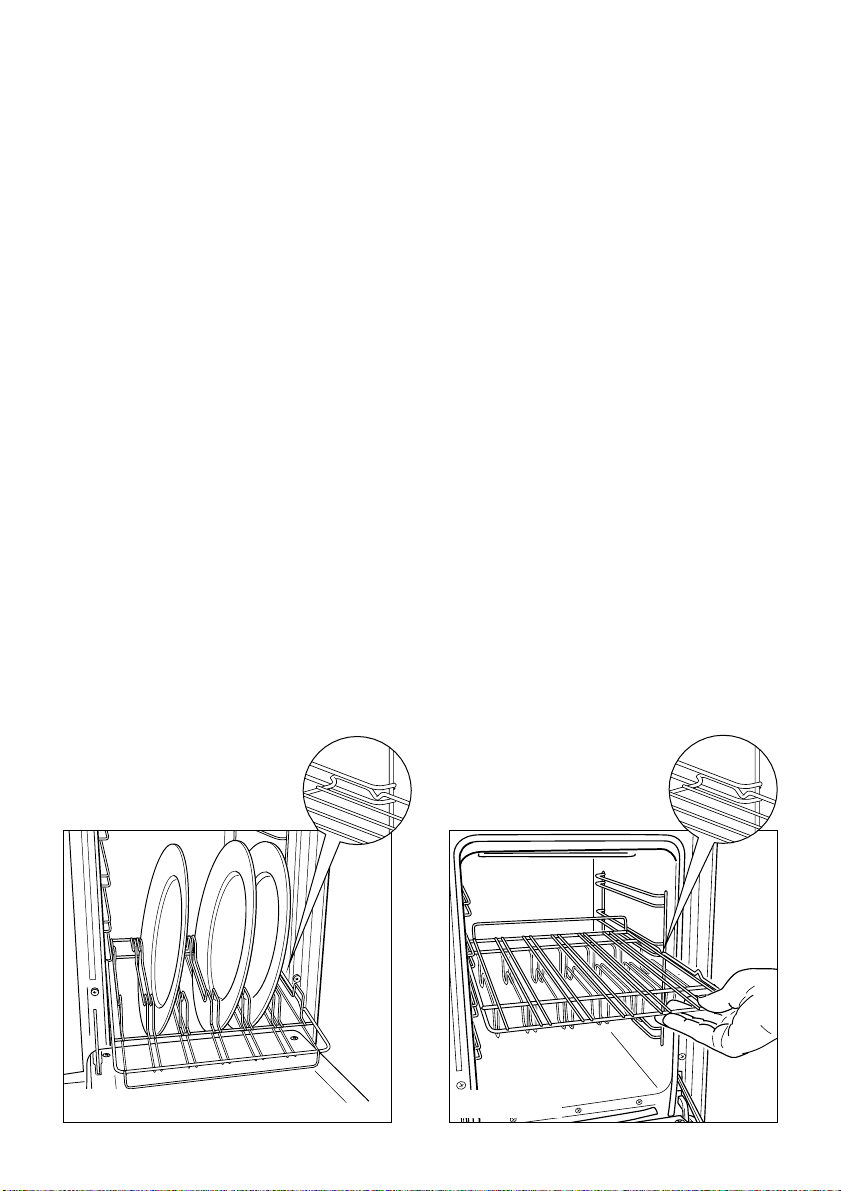
USE OF SPECIAL DISH RACK
This special shelf can be used as a dish rack or when turned over, as a normal shelf for
oven cooking.
It must be inserted between the guides of the lateral racks.
USING THE SPECIAL SHELF AS A DISH RACK
Slide in the shelf on the guides, on the lower level of the lateral racks.
The prongs where the plates are to be inserted must be turned upwards.
The shelf must be fitted so that the safety catch, which stops it sliding out, faces the bottom of the oven (see detail of figure 5.3).
The plates must be positioned as indicated in figure 5.3.
To facilitate this operation pull the special rack up to the safety lock.
KEEP ATTENTION: Plates are hot after warming. It is advisable to handle the plates
using oven gloves.
USING THE SPECIAL RACK FOR NORMAL COOKING
Slide in the shelf on the guides: the safety catch must be turned toward the oven base
(see detail of figure 5.4).
The flat surface can be used to put cooking pans or to put food directly on the rack; in the
second case the drip tray should be placed under the rack to catch the cooking juices and
fats.
Fig. 5.3
Fig. 5.4
Page 18
18
NOTE: Reduce the oven temperature by 10 – 20°C for fan assisted ovens.
For dishes that take over an hour to cook, reduce the cooking time by 10 minutes per
hour.
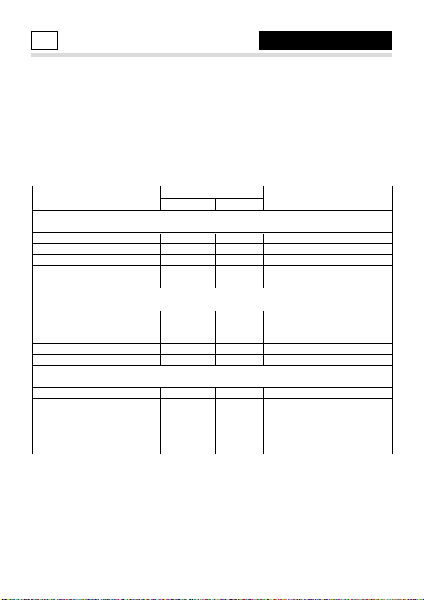
COOKING CHART
Food
Temperature
Cooking Time (approx)
°C Gas Mark
CAKES
Victoria Sandwich 180 4 20 – 25 mins
Small cakes/buns 180 4 15 – 20 mins
Rich Fruit Cake 150 2 2 hours
Scones 220 7 – 8 8 – 10 mins
Whisked Sponge 190 5 25 mins
BREAD & PASTRY
Bread Loaf (500g Flour wt) 225 7 – 8 20 – 25 mins
Bread Rolls 225 7 – 8 10 – 15 mins
Pizza Dough 225 8 15 – 20 mins
Shortcrust pastry 200 6 20 – 30 mins
Quiches/Flans 180 - 190 4 - 5 30 – 40mins
ROAST MEATS
Beef – medium joint 190 5 20 – 25 mins/lb + 20mins
Lamb 190 5 25 – 30mins/lb + 25mins
Pork 190 5 30mins/lb + 30mins
Chicken 190 5 20 – 25mins/lb + 30mins
Turkey 180 4 15 – 20mins/lb + 20mins
Stews/Casseroles 170 3 11/2 - 2hours
Temperature and times given are approximate, as they will vary depending on the quality
and amount of food being cooked.
Remember to use ovenproof dishes and to adjust the oven temperature during cooking
if necessary.
COOKING GUIDE
6
Page 19
19
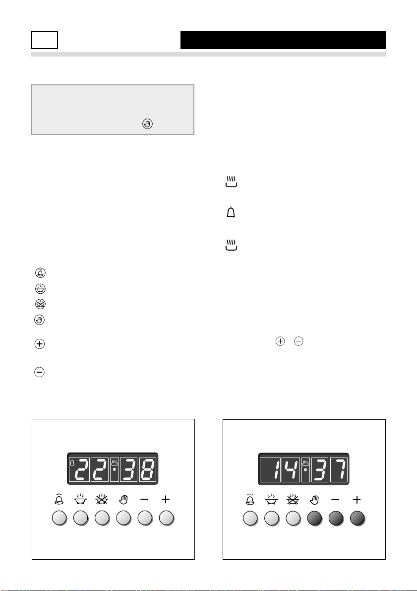
Fig. 7.2
Fig. 7.1
ELECTRONIC PROGRAMMER
7
MAIN OVEN ONLY
Description of the illuminated
symbols:
AUTO - flashing - Programmer in auto-
matic position but not programmed
AUTO - always lit - Programmer in auto-
matic position with program set.
Automatic cooking taking place
Timer in operation
and AUTO - flashing - Program
error.
(The time of day lies between the
calculated cooking start and end
time).
Note:
Select a function by the respective button and, in 5 seconds, set the required
time with the / buttons (“one-hand”
operation).
A power cut makes the clock go to zero
and cancels the set programs.
Description of the buttons:
Timer
Cooking time
End of cooking time
Manual position and cancellation of
the set cooking program
Advance the time for of all pro-
grams
Decrease the program time and
changing the frequency of the audible signal.
The electronic programmer performs the
following functions:
– 24 hours clock with illuminated display
– Timer (up to 23 hours and 59 minutes)
– Program for automatic oven cooking
– Program for semi-automatic oven
cooking.
If you use the oven for none automatic or semi-automatic cooking,
ensure programmer is set to manual position by pushing button.
A
U
T
O
Page 20
20
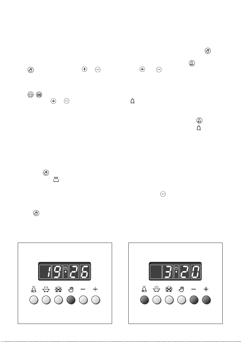
Fig. 7.3
Fig. 7.4
ELECTRONIC CLOCK(fig. 7.2)
The programmer is equipped with an
electronic clock with an illuminated display which indicates hours and minutes.
Upon immediate connection of the oven
or after a powercut, three zeros will flash
on the display panel.
To set the hour it is necessary to push
the button and then the or button until you have set the exact hour (fig.
7.2).
Another way is to simultaneously push
the two buttons and at the same
time push the or button.
Note: The hour setting deletes any program.
ELECTRONIC TIMER
The timer program consists only of a
buzzer which may be set for a maximum
period of 23 hours and 59 minutes.
If the AUTO is flashing push the button.
To set the time, push the button and
the or until you
obtain the desired time in the panel (fig.
7.4).
Having finished the setting, the clock
hour will appear on the panel and the
symbol will be lit.
The countdown will start immediately and
may be seen at any moment on the panel
by simply pressing the button .
At the end of the time, the symbol
will be switched off and an intermittent
buzzer will go off; this can be stopped by
pressing any of the buttons.
SETTING THE FREQUENCY OF THE
AUDIBLE SIGNAL
3 possible sounds can be selected by
pressing the button.
NORMAL COOKING WITHOUT THE
USE OF THE PROGRAMMER
To manually use the oven, that is, without
the aid of the programmer, it is necessary
to cancel the flashing AUTO by pushing
the button (AUTO will be switched off
and the symbol will go on - Fig. 7.3).
Attention: If the AUTO is steadily lit (which
means a cooking program has already
been set), the program can be cancelled
and switched to manual by pushing the
button .
If the oven is switched on, you must
switch off manually.
A
U
T
O
Page 21
21
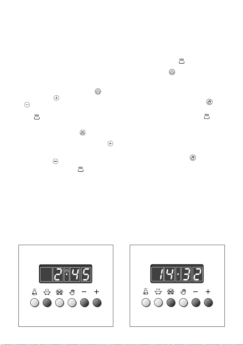
Fig. 7.6
Fig. 7.5
3. Set the temperature and the cooking
program (see the relevant sections).
Once the oven is programmed it will
switch on automatically at the right time
to stop the cooking at the desired end
time.
During cooking, the symbol remains
on.
By pushing the button you can see
the time that remains until the end of
cooking.
The cooking program may be cancelled at any time by pushing .
At the end of the cooking time the oven
will turn off automatically, the symbol will turn off, AUTO will flash and the
buzzer will sound, which can be turned
off by pushing any of the buttons.
Turn the switch and temperature knobs
to "OFF" and put the programmer onto
“manual” by pressing the button.
Attention: A powercut will make the
clock go to zero and will cancel the set
programs.
After a powercut, three zeros will flash
on the panel.
AUTOMATIC OVEN COOKING
To cook food automatically in the oven,
it is necessary to:
1. Set the length of the cooking time
2. Set the end of the cooking time
3. Set the temperature and the oven
cooking program.
These operations are done in the following way:
1.Set the length of time you need to
cook the food by pushing the button and the button to advance, or
to go back if you have passed the
desired time (fig. 7.5). The AUTO and
the symbol will be on.
2.Set the time you need the food to stop
cooking by pushing the button (the
cooking time already added to the
clock time will appear), and the
button (fig. 7.6); if you pass the
desired time you can go back by
pushing the button.
After this setting, the symbol will
go off. If after this setting, the AUTO
flashes on the panel and a buzzer
goes off, it means there was an error
in the programming, that is the cooking cycle has been superimposed on
the clock. In this case, change the end
of cooking time or the cooking time
itself by following the instructions
above.
A
U
T
O
A
U
T
O
Page 22
22
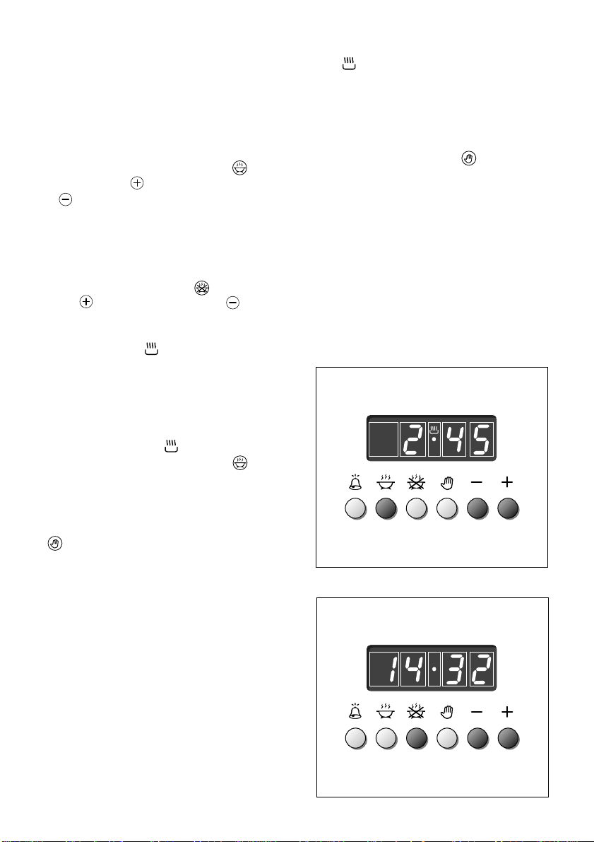
Fig. 7.7
Fig. 7.8
At the end of the cooking, the oven and
the symbol will turn off, the AUTO
will flash and a buzzer will go off which
can be stopped by pushing any of the
buttons.
Turn the switch and temperature knobs
to "OFF" and put the programmer onto
“manual” by pressing the button.
SEMI - AUTOMATIC COOKING
This is used to switch the oven off automatically after the desired cooking time
has elapsed.
There are two ways to set the semiautomatic cooking function:
1.Set the length of time you need to
cook the food by pushing the button and the button to advance, or
to go backwards (Fig. 7.7).
This sets the desired “stop” time.
or
2.Set the time you need the food to stop
cooking by pushing the button and
the button to advance, or to go
backwards if you have passed the
desired time (Fig. 7.8).
AUTO and the symbol will be on.
Then set the temperature and the cooking program (see the relevant sections).
The oven is switched on and it will
switch off automatically at the end of the
desired time.
During cooking, the symbol remains
on and by pressing the button you
can see the time that remains until the
end of the cooking.
The cooking program can be cancelled at any moment by pushing the
button.
A
U
T
O
A
U
T
O
Page 23

23
GENERAL ADVICE
– When the appliance is not being
used, it is advisable to keep the gas
tap closed.
– Every now and then check to make
sure that the flexible tube that connects the gas line or the gas cylinder
to the appliance is in perfect condition
and get it replaced if it shows any
signs of wearing or damage.
– The periodical lubrication of the gas
taps must be done only by specialised
personnel.
– If a tap becomes stiff, do not force;
contact your local Service Centre.
Important:
Before cleaning or carrying out
any maintenance disconnect the
appliance from the electrical supply and wait for it to cool down.
Attention
The appliance gets very hot,
mainly around the cooking areas.
It is very important that children
are not left alone in the kitchen
when you are cooking.
Do not use a steam cleaner
because the moisture can get
into the appliance thus make it
unsafe.
REPLACING THE OVEN LIGHT BULB
Switch the cooker off at the mains.
When the oven is cool, unscrew and
replace the bulb with another one
resistant to high temperatures (300°C),
voltage 230 V (50 Hz), 15 W, E14.
Note: Oven bulb replacement is not
covered by your guarantee.
GAS TAPS
In the event of operating faults in the gas
taps, call the After Sales Service
Department.
ENAMELLED PARTS
All the enamelled parts must be cleaned
with a sponge and soapy water or other
non-abrasive products.
Dry preferably with a soft cloth.
Acidic substances like lemon juice,
tomato sauce, vinegar etc. can damage
the enamel if left too long.
STAINLESS STEEL, ALUMINIUM
PARTS AND SILK-SCREEN PRINTED
SURFACES
Clean using an appropriate product.
Always dry thoroughly.
IMPORTANT: these parts must be
cleaned very carefully to avoid scratching
and abrasion. You are advised to use a
soft cloth and neutral soap.
CAUTION: Do not use abrasive
substances or non-neutral detergents
as these will irreparably damage the
surface.
CLEANING AND MAINTENANCE
8
Page 24
24
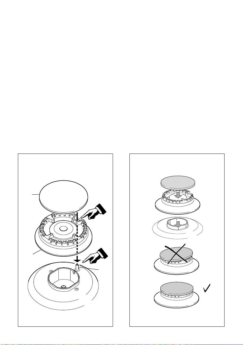
Fig. 8.2
Fig. 8.1
S
F
C
BURNERS
The burners can be removed and washed
with soapy water only.
They will remain perfect if always
cleaned with products used for silverware.
After cleaning, check that the burnercaps and burner-heads are dry before
placing them in the respective hous-
ings.
CORRECT REPLACEMENT OF THE
BURNERS
It is very important to check that the
burner flame distributor F and the cap C
has been correctly positioned (see figs.
8.1 - 8.2) - failure to do so can cause a
poor burner flame and/or damage to the
burner and hob.
Check that the electrode “S” (fig. 8.1) is
always clean to ensure trouble-free
sparking.
Note: To avoid damage to the electric
ignition do not use it when the burners are not in place.
Page 25
25
Fig. 8.5
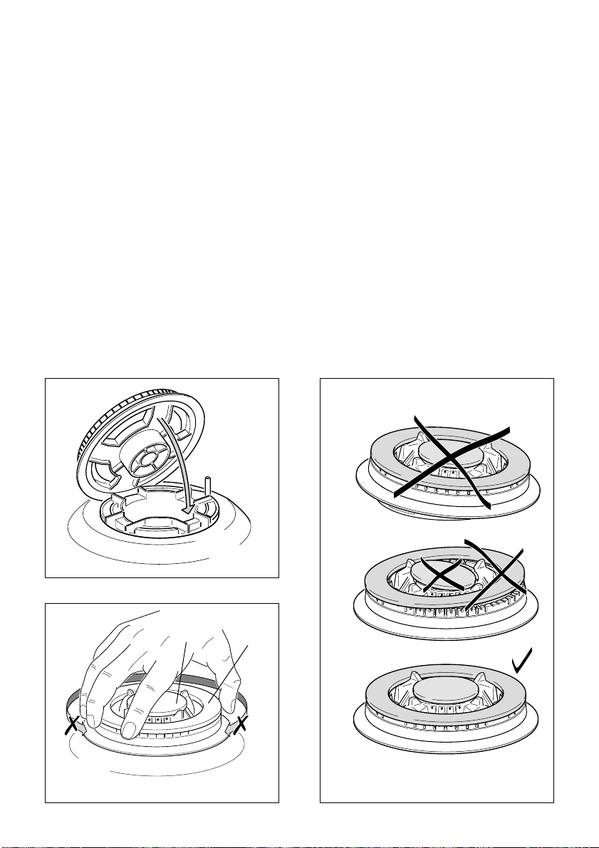
TRIPLE RING BURNER
The triple ring burner must be correctly positioned (see fig. 8.3); the burner rib must be
enter in their logement as shown by the arrow.
The burners must be correctly positioned so that they cannot rotate (fig. 8.4).
Then position the cap A and the ring B (fig. 8.4 - 8.5).
Fig. 8.3
Fig. 8.4
A
B
Page 26
26
Fig. 8.7
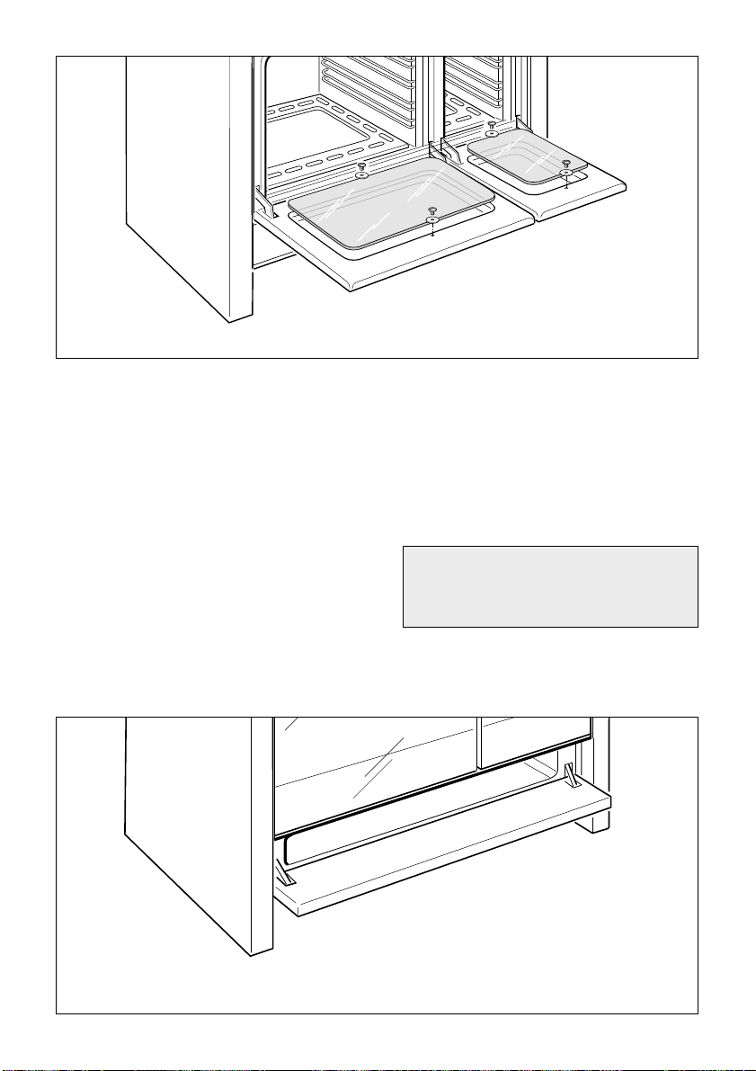
OVEN DOOR
The internal glass panel can be easily
removed for cleaning by unscrewing the
2 retaining screws (Fig. 8.6)
Do not store flammable material in
the oven or in the storage compartment.
STORAGE COMPARTMENT
The storage compartment is accessible
through the pivoting panel (fig. 8.7).
Fig. 8.6
Page 27
27
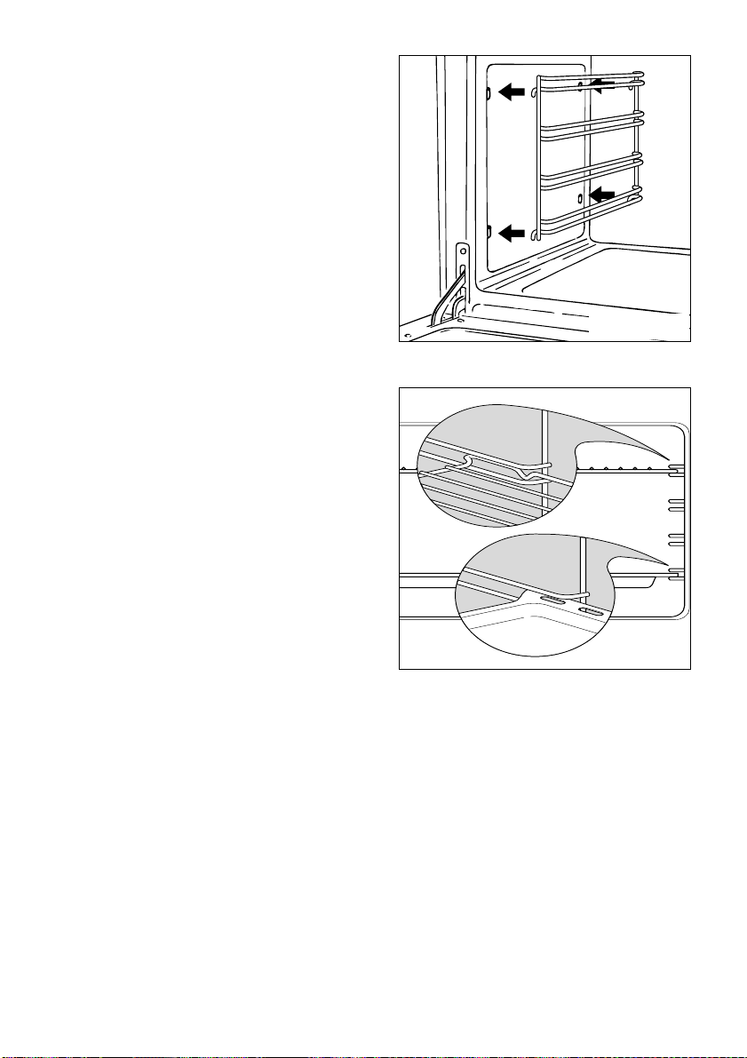
ASSEMBLY AND DISMANTLING OF
THE SIDE RUNNER FRAMES
– Fit the side runner frames into the
holes on the side walls inside the
oven (Fig. 8.8).
– Slide the tray and rack into the run-
ners (Fig. 8.9).
The shelf must be fitted so that the
safety catch, which stops it sliding out,
faces the inside of the oven.
– To dismantle, operate in reverse
order.
Fig. 8.8
Fig. 8.9
INSIDE OF OVEN
This must be cleaned after every use.
Remove and refit the side runner frames
as described on the next chapter.
With the oven warm, wipe the inside
walls with a cloth soaked in very hot
soapy water or another suitable product.
Side runner frames, tray and rack can
be removed and washed.
Page 28
28
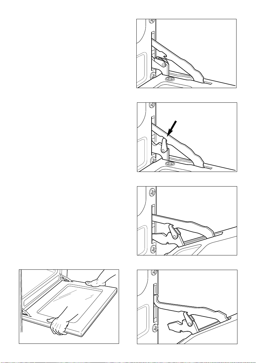
The oven door can easily be removed as
follows:
– Open the door to the full extent (fig.
8.10A).
– Attach the retaining rings to the hooks
on the left and right hinges (fig. 8.10B).
– Hold the door as shown in fig. 8.10.
– Gently close the door and withdraw the
lower hinge pins from their location
(fig. 8.10C).
– Withdraw the upper hinge pins from
their location (fig. 8.10D).
– Rest the door on a soft surface.
– To replace the door, repeat the above
steps in reverse order.
Fig. 8.10D
Fig. 8.10C
Fig. 8.10B
Fig. 8.10A
REMOVING THE OVEN DOOR
Fig. 8.10
Page 29

29
IMPORTANT
– Cooker installation must only be carried out by QUALIFIED TECHNICIANS and in
compliance with local safety standards. Failure to observe this rule will invalidate the
warranty.
The appliance must be installed in compliance with regulations in force in your country
and in observation of the manufacturer's instructions.
– The surfaces of adjacent furniture and walls must be capable of withstanding tempera-
tures in excess of 75˚C.
– Some appliances are supplied with a protective film on steel and aluminium parts.
This film must be removed before using the cooker.
ADVICE
FOR THE
INSTALLER
Page 30
30
The veneered synthetic material and the glue used must be resistant to a temperature of 90°C
in order to avoid ungluing or deformations.
The cooker may be located in a kitchen, a kitchen/diner or bed-sitting room but not in a room
containing a bath or shower.
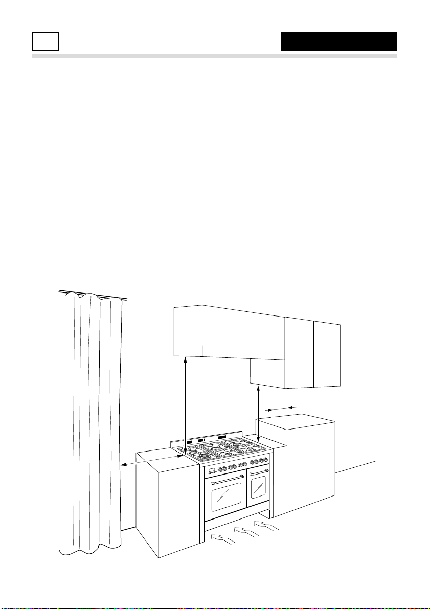
Curtains must not be fitted immediately behind appliance or within 500 mm of the sides.
It is essential that the cooker is positioned as stated below.
If the cooker is located on a pedestal it is necessary to provide safety measures to prevent
falling out.
The cooker must be installed by a qualified technician and in compliance with local
safety standards.
Fig. 9.1
This cooker has class “2/1” overheating protection so that it can be installed next
to a cabinet.
If the cooker is installed adjacent to furniture which is higher than the gas hob cooktop, a
gap of at least 200 mm must be left between the side of the cooker and the furniture.
The furniture walls adjacent to the cooker must be made of material resistant to heat.
750 mm
500 mm
450 mm
200 mm
air flow
INSTALLATION
9
Page 31
31
Fig. 9.2
+ 8 mm
+ 8
0
mm
+ 35 mm
Fig. 9.3
Fig. 9.4
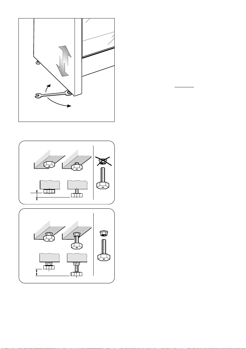
LEVELLING THE COOKER
The cooker is equipped with 4 LEVELLING FEET and may be levelled by
screwing or unscrewing the feet with a
spanner (fig. 9.2).
The adjustable feet are already fitted to
the cooker but the locking nuts which
can be found in the main oven packaging
require to be fitted as detailed below.
It is important to observe
the prescrip-
tions of figures 9.3 - 9.4.
Page 32
32
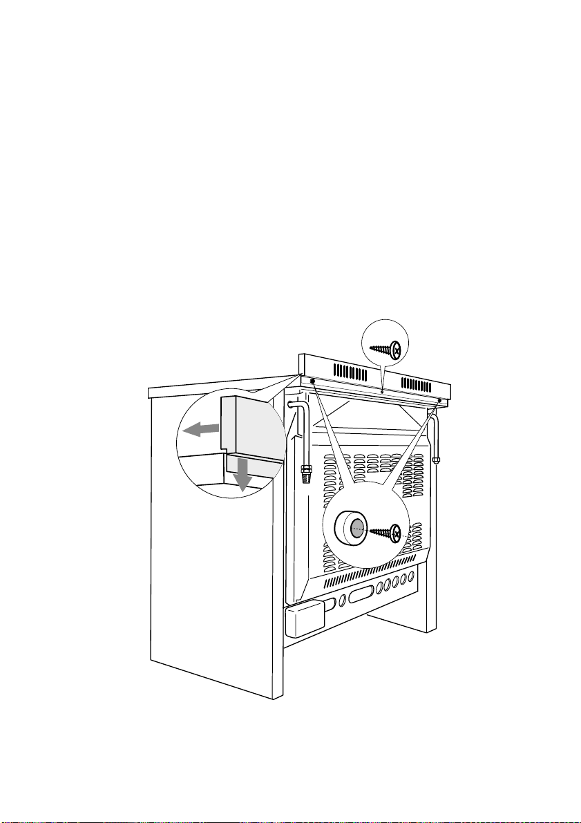
ASSEMBLING THE BACKGUARD
• Remove the two spacers “A” and the
screw “B” from the rear of the cooktop.
• Assemble the backguard as shown in
figure 9.5 and fix it by screwing the
central screw “B” and the spacers “A”.
Fig. 9.5
A
B
Page 33
33
Fig. 9.6
Fig. 9.7
Fig. 9.8
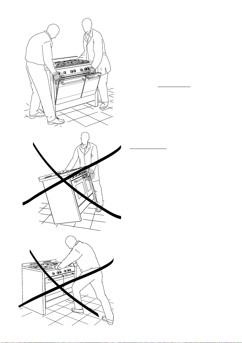
MOVING THE COOKER
WARNING
When raising cooker to upright position
always ensure two people carry out this
manoeuvre to prevent damage to the
adjustable feet (fig. 9.6).
WARNING
Be carefull: DO NOT LIFT
the cooker by
the door handle when raising to the
upright position (fig. 9.7).
WARNING
When moving cooker to its final position
DO
NOT DRAG (fig. 9.8).
Lift feet clear of floor (fig. 9.6).
Page 34
34
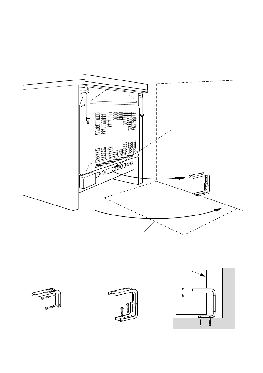
STABILITY BRACKET
We recommend a stability bracket is fitted to the cooker.
The type shown in fig. 9.9 can be purchased from most plumbers merchants and do
it yourself (D.I.Y.) shops.
Wall fixing
Floor fixing
Brackets
Existing
slot in rear
of cooker
Dotted line showing the
position of cooker when fixed
Dimension is in millimetres
3
Outline of cooker
backplate at the
engagement slot
Fig. 9.9
Page 35
35
PROVISION FOR VENTILATION
The room containing the cooker should have an air supply in accordance with BS.5540:
Part 2: 1989.
All rooms require an openable window or equivalent while some rooms require a
permanent vent in addition to the openable window.
The cooker should not be installed in a bed-sitting room, of volume less than 21 m
3
.
Where a DOMESTIC COOKER is installed in a room or internal space, that room or
internal space shall be provided with a permanent opening which communicates directly
with outside air and is sized in accordance with the table below. In domestic premises the
permanent opening shall be an air vent.
If there are other fuel burning appliances in the same room, BS.5540: Part 2: 1989 should
be consulted to determine the requisite air vent requirements.
If the cooker is installed in a cellar or basement, it is advisable to provide an air vent of
effective area 100 cm
2
, irrespective of the room volume.
(❊)
If the room or internal space containing these appliances has a door which
opens directly to outside, no permanent opening is required.
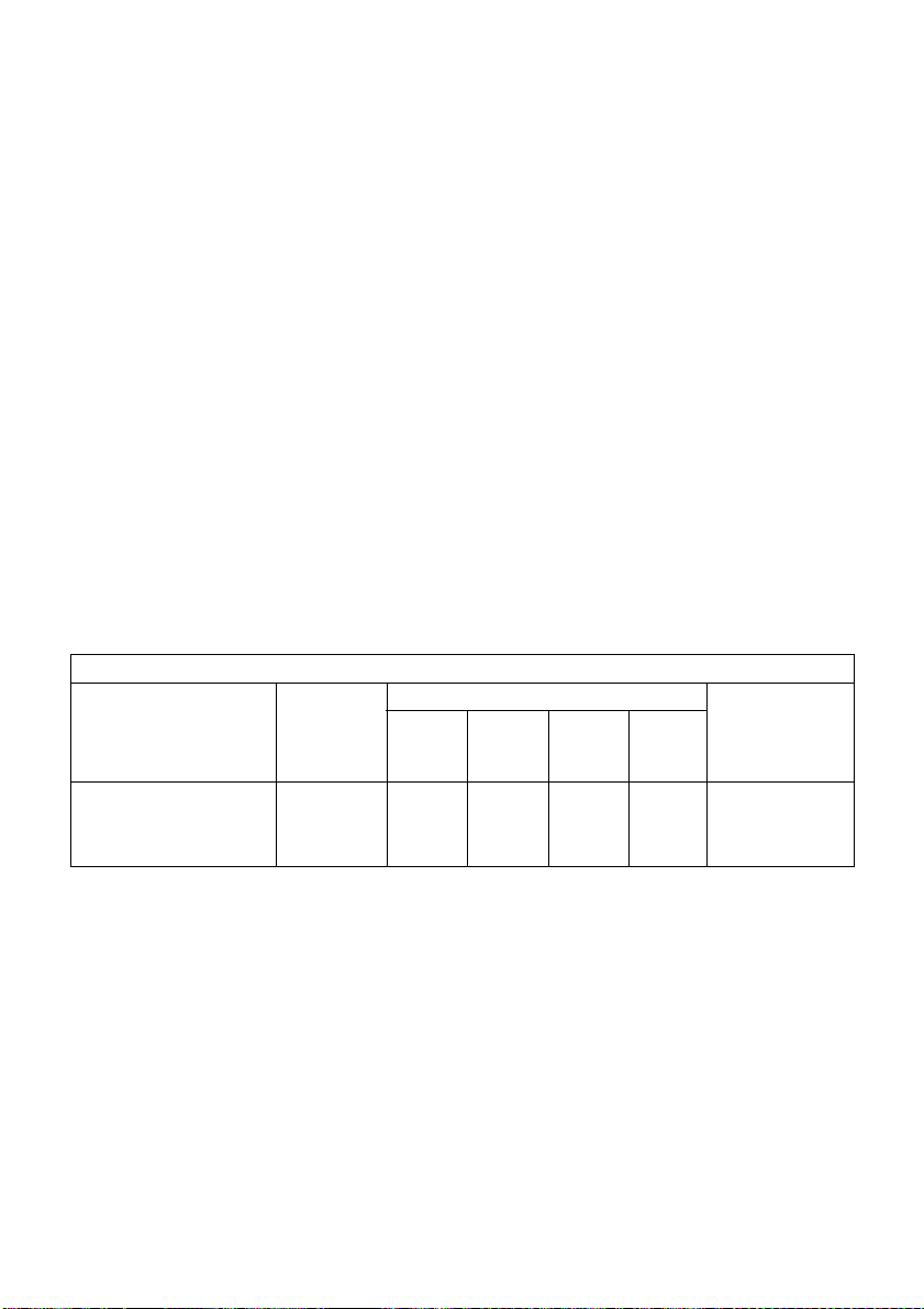
MINIMUM PERMANENT OPENING FREE AREA FOR FLUELESS APPLIANCE
5 m3to 10
m
3
Openable
window or
equivalent also
required
Maximum
appliance
rated input
limit
Room volume
11 m3to
20 m
3
> 20 m
3
< 5 m
3
Type of appliance
Domestic oven,
hotplate, grill or any
combination thereof.
None
50 (❊)
cm
2
Nil
cm
2
Nil
cm
2
100
cm
2
Yes
Page 36

36
GAS INSTALLATION
IMPORTANT NOTE
This appliance is supplied for use on
NATURAL GAS only and cannot be
used on any other gas without
modification.
This appliance is manufactured for
conversion to LPG if required and is
supplied with a conversion kit.
The cooker must be installed by a
qualified person in accordance with the
Gas Safety (Installation and Use)
(Amendment) Regulation 1990 and the
relevant building/l.E.E. Regulations.
The following British Standards should
be used as reference when installing
this appliance.
BS6172 1990, BS5440 part 2 1989 and
BS6891 1988.
Failure to install the appliance correctly
could invalidate any manufacturers
warranty and lead to prosecution under
the above quoted regulation.
In the UK C.O.R.G.I registered installers
are authorised to undertake the
installation and service work in
compliance with the above regulations.
GAS CONNECTION
The installation of the cooker to Natural
Gas or LP Gas must be carried out by
a qualified gas engineer. Installers shall
take due account of the provisions of the
relevant British Standards Code of
Practice, the Gas Safety Regulations
and the Building Standards (Scotland)
(Consolidation) Regulations issued by
the Scottish Development Department.
INSTALLATION TO NATURAL GAS
Installation to Natural Gas must conform
to the Code of Practice, etc. The supply
pressure for Natural Gas is 20 mbar.
INSTALLATION TO LP GAS
This appliance must only be connected
to LPG after an LPG conversion kit has
been fitted, (see pages from 38 to 40).
When operating on Butane gas a supply
pressure of 28-30 mbar is required.
When using Propane gas a supply
pressure of 37 mbar is required.
The installation must conform to the
relevant British Standards.
Warning: Only a qualified gas engineer,
also with technical knowledge of
electricity should install the cooker. He
should observe the Regulations and
Codes of Practice governing such
installation of gas cookers.
Note: It is recommended that the gas
connection to the cooker is installed with
a flexible connecting tube made to BS
5386.
GAS SECTION
10
Page 37
37
GAS CONNECTION
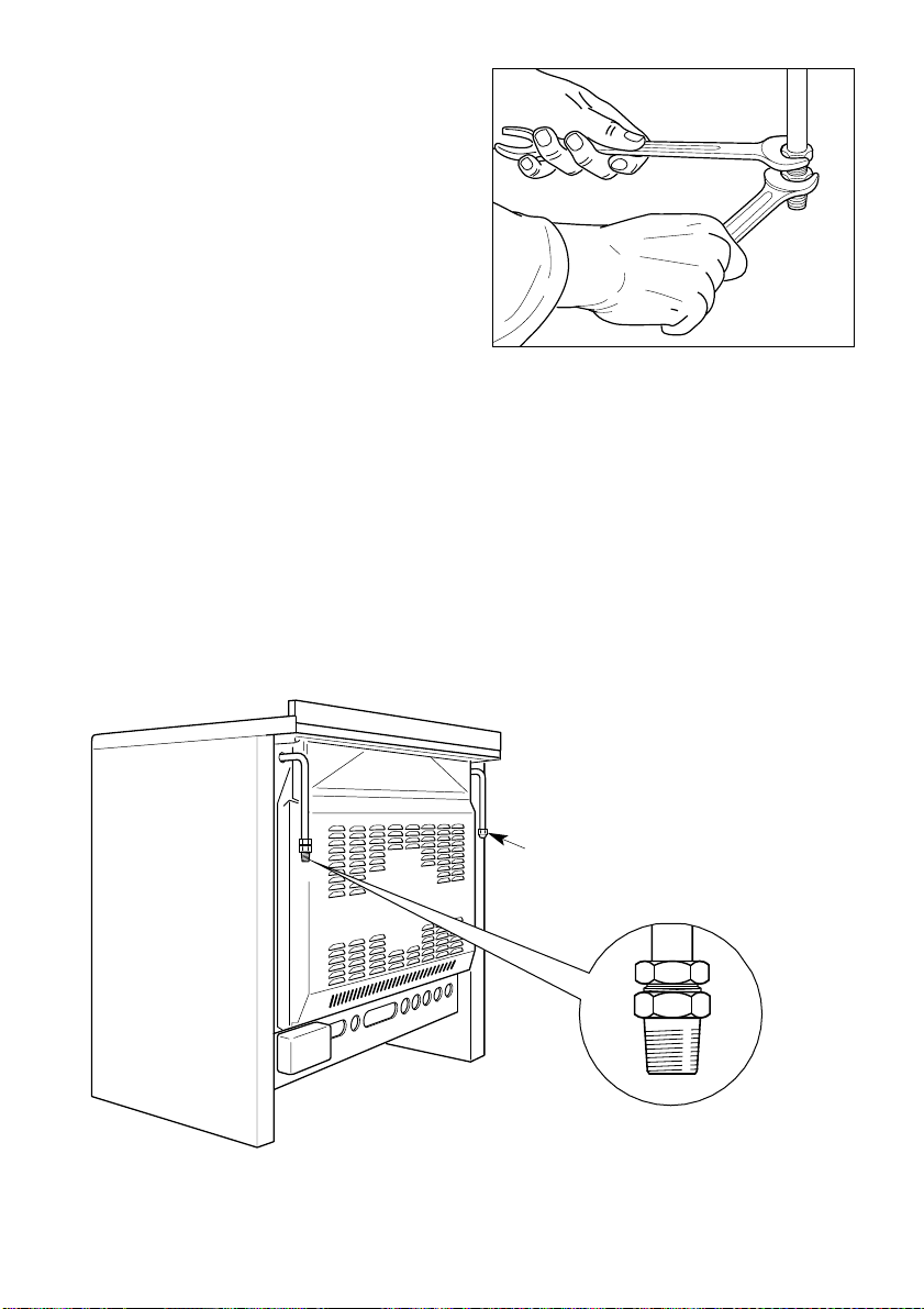
The gas supply must be connected to
the gas inlet which is located at the left
or the right hand rear of the appliance
(fig. 10.1).
The pipe does not cross the cooker.
When screwing the connecting tube
operate with two spanners (fig. 10.2).
The unused end inlet pipe must be
closed with the plug, interposing the
gasket.
After connecting to the mains, check
that the coupling are correctly sealed,
using soapy solution, but never a
flame.
Fig. 10.2
Fig. 10.1
Plug
Page 38
38
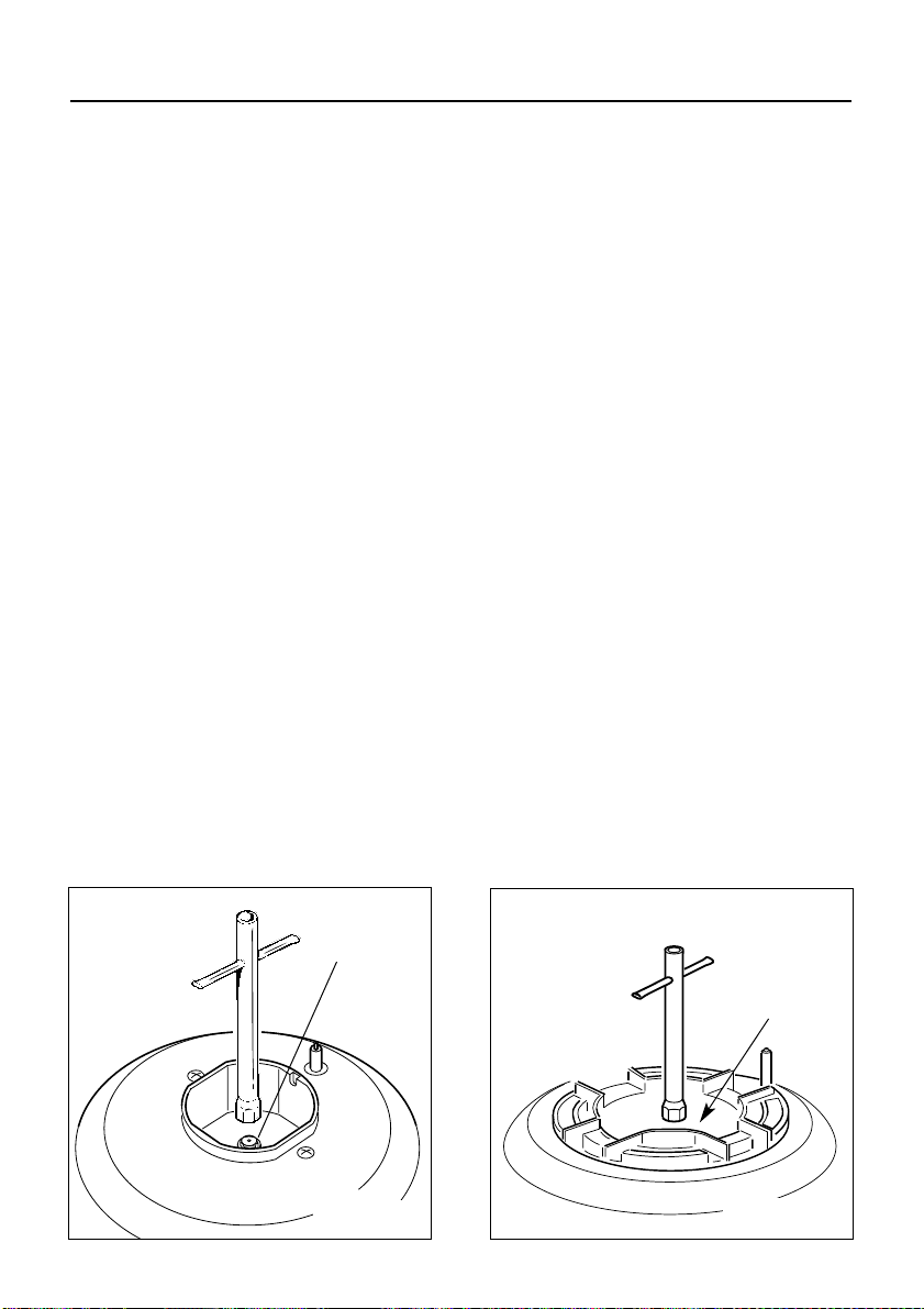
Fig. 10.3
J
J
Fig. 10.4
1 - INJECTORS REPLACEMENT OF
HOB BURNERS
The diameter is marked on the injector
in cents of millimetre.
Select the injectors to be replaced
according to the “Table for the choice of
the injectors” (page 40).
To replace the injectors:
– Remove the gratings, the burner and
the covers;
– Using a wrench, substitute the nozzle
injectors “J” (Fig. 10.3 - 10.4) with
those most suitable for the kind of gas
for which it is to be used.
The burners are conceived in such a
way so as not to require the regulation
of the primary air.
CONVERSION TO LPG
Page 39
39
LUBRICATION OF THE GAS TAPS
If a tap becomes stiff, do not force;
contact your local Service Agent.
IMPORTANT
All interventions regarding
installation maintenance of the
appliance must be fulfilled with
original factory parts.
The manufacturer declines any
liability resulting from the noncompliance of this obligation.
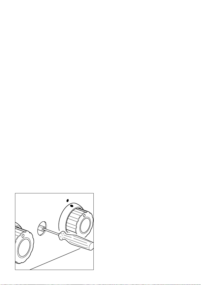
2 - ADJUSTING OF THE MINIMUM
OF THE HOB BURNERS
In the minimum position the flame must
have a length of about 4 mm and must
remain lit even with a quick turn from the
maximum position to that of minimum.
The flame adjustment is done in the following way:
– Turn on the burner
– Turn the tap to the MINIMUM position
– Take off the knob
– With a small flat screwdriver turn the
screw inside the tap rod to the correct
regulation (fig. 10.5).
Normally for LPG, tighten up the regulation screw.
Fig. 10.5
Page 40
40
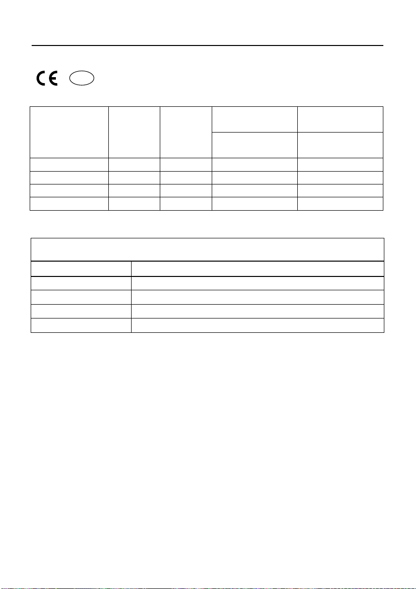
INCREASE OF AIR NECESSARY FOR GAS COMBUSTION
(2 m3/h x kW)
BURNERS Air necessary for combustion [m
3
/h]
Auxiliary (A) 2,00
Semi-rapid (SR) 3,50
Rapid (R) 6,00
Triple-ring 7,00
TABLE FOR THE CHOICE OF THE INJECTORS
Cat: II 2H3+
BURNERS
Nominal
Power
[kW]
Reduced
Power
[kW]
G30- 28-30 mbar
G31- 37 mbar
G20
20 mbar
Ø injector
[1/100 mm]
Ø injector
[1/100 mm]
Auxiliary (A) 1,00 0,30 50 72 (X)
Semirapid (SR) 1,75 0,45 65 97 (Z)
Rapid (R) 3,00 0,75 85 115 (Y)
Triple-ring (TR) 3,50 1,50 95 135 (T)
GB
Page 41

41
N.B. For connection to the mains, do
not use adapters, reducers or
branching devices as they can cause
overheating and burning.
If the installation requires alterations to
the domestic electrical system call an
expert.
He should also check that the socket
cable section is suitable for the power
absorbed by the appliance.
GENERAL
– Connection to the mains must be car-
ried out by qualified personnel in
accordance with current regulations.
– The appliance must be connected to
the mains checking that the voltage
corresponds to the value given in the
rating plate and that the electrical
cable sections can withstand the load
specified on the plate.
– The appliance can be connected
directly to the mains placing an
omnipolar switch with minimum opening between the contacts of 3 mm
between the appliance and the mains.
– The power supply cable must not
touch the hot parts and must be positioned so that it does not exceed 75°C
at any point.
– Once the appliance has been
installed, the switch must always be
accessible.
IMPORTANT: The cooker must be
installed in accordance with the
manufacturer’s instructions.
Incorrect installation, for which the
manufacturer accepts no responsibility, may cause injury to persons
or animals etc.
Before effecting any intervention
on the electrical parts of the appliance, the connection to the network must be interrupted.
The connection of the appliance
to earth is mandatory.
The manufacturer declines all
responsibility for any inconvenience resulting from not
observing this condition.
IMPORTANT: this cooker must be
connected to a suitable double
pole control unit adjacent to the
cooker.
NO DIVERSITY CAN BE APPLIED
TO THIS CONTROL UNIT.
IMPORTANT:
This appliance must be earthed.
ELECTRICAL SECTION
11
Page 42
42
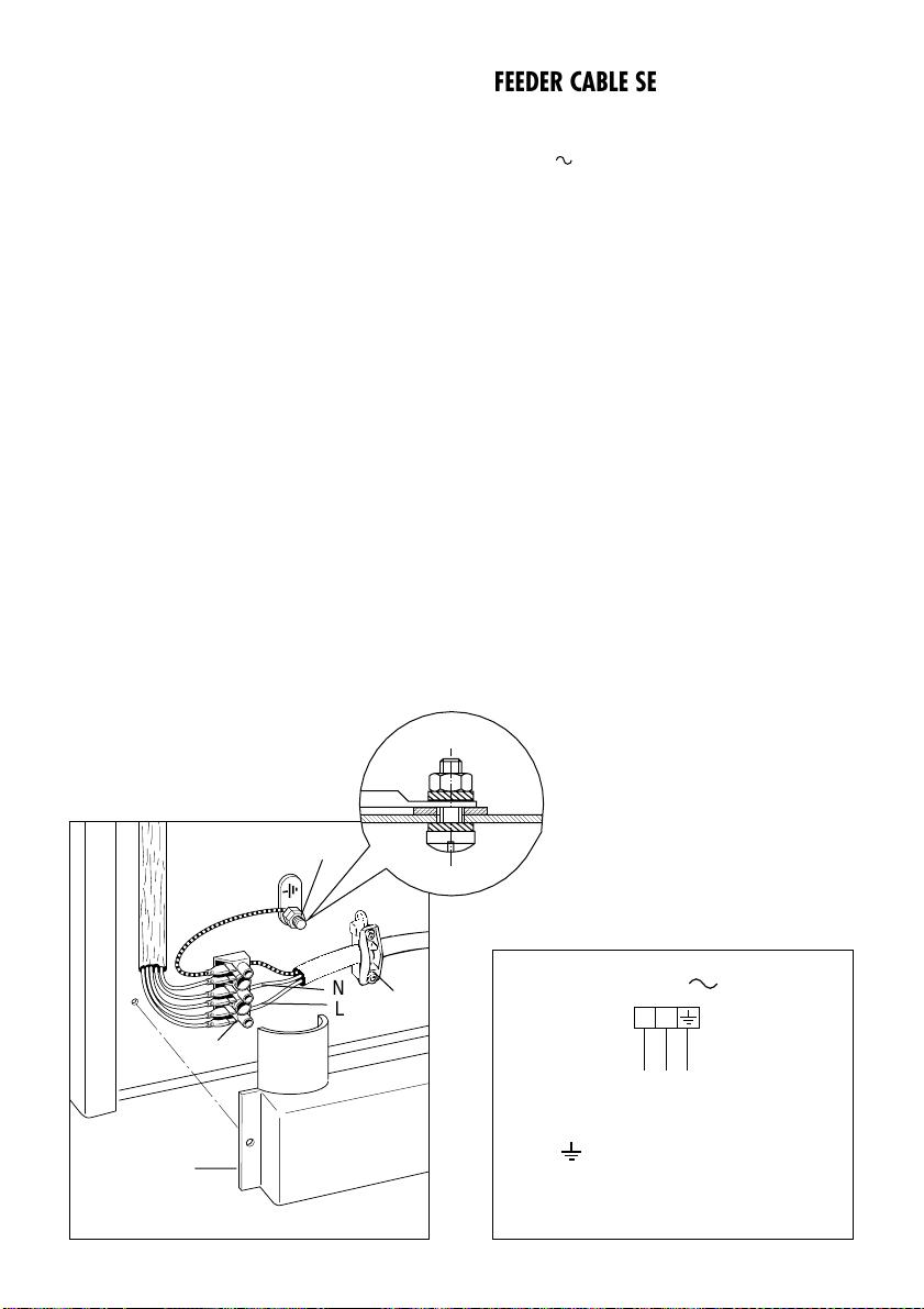
ELECTRICAL FEEDER CABLE
CONNECTION
To connect the supply cable:
- Remove the screws securing the
cover “A” on the rear of the cooker
(fig. 11.1).
- Feed the supply cable through the
cable clamp “D”. The supply cable
must be of a suitable size for the
current requirements of the appliance;
see the section “Feeder cable section”
(fig. 11.1).
- Connect the wires to the terminal
block “B” as shown in the diagram in
figure 11.2; or connect the phase
wires to the terminal block “B” and the
earth wire to the terminal PE as
shown in figure 11.1.
- Take up any slack in the cable and
secure with the cable clamp “D”.
- Replace the cover “A”.
N.B. The earth conductor must be left
about 3 cm longer than the others.
Fig. 11.1
D
B
PE
A
N
L
FEEDER CABLE SECTION TYPE
HO5RR-F
230 V 3 x 2,5 mm
2
Fig. 11.2
PE Earth
N Neutral
L Live
230 V
L
1
PEN
(L2)
Page 43

43
Descriptions and illustrations in this booklet are given as simply indicative.
The manufacturer reserves the right, considering the characteristics of the models described here, at any time and
without notice, to make eventual necessary modifications for their construction or for commercial needs.
Your Prestige from COMET
Your new Prestige product comes with 12-month guarantee covering all parts and labour.
If your appliance proves to be defective as a result of faulty materials or workmanship
during the guarantee COMET will repair or replace it free of charge.
AFTER SALES SERVICE
Should you require to book a service call.
Please Telephone 08705 425425.
For product information and advice.
Please Telephone 0113 2793520.
1. The right and benefits under this guarantee are additional to your statutory rights,
which are not affected by this guarantee.
2. COMET undertakes within the specified period, to repair or replace free of charge any
parts of the appliance found to be defective provided this:
• We are promptly informed of the defect
• The appliance is installed and used in accordance with the written instructions
enclosed with the appliance
• The appliance is used only on an electrical supply as indicated on the rating label
fixed to the appliance
• The appliance has not been altered in any way or subject to misuse or repair by a
person other than an authorised service agent for COMET
3. No rights are given under this guarantee to a person acquiring the appliance second
hand or for commercial or communal use.
4. This guarantee applies throughout the UK Channel Islands.
5. Any replaced parts shall be the property of COMET
6. Any repaired or replacement appliances will be guaranteed on these terms for the
unexpired portion of the guarantee.
IMPORTANT INFORMATION FOR CORRECT DISPOSAL OF THE PRODUCT IN
ACCORDANCE WITH EC DIRECTIVE 2002/96/EC.
At the end of its working life, the product must not be disposed of as
urban waste. It must be taken to a special local authority differentiated
waste collection centre or to a dealer providing this service.
Disposing of a household appliance separately avoids possible negative
consequences for the environment and health deriving from inappropriate
disposal and enables the constituent materials to be recovered to obtain
significant savings in energy and resources. As a reminder of the need to
dispose of household appliances separately, the product is marked with a
crossed-out wheeled dustbin.
Page 44

code 1102457 ß11
Prestige®is a registered trademark of Meyer Intellectual
Properties Limited and is sold pursuant to a license.
 Loading...