

Prestige Solo 24, Solo 32, AquaSpeed 24, AquaSpeed 32, Excellence 24 Installation, Operating And Servicing Instructions
...Page 1
EN • 1
ENGLISHFRANCAISNEDERLANDSESPAÑOLITALIANODEUTSCH
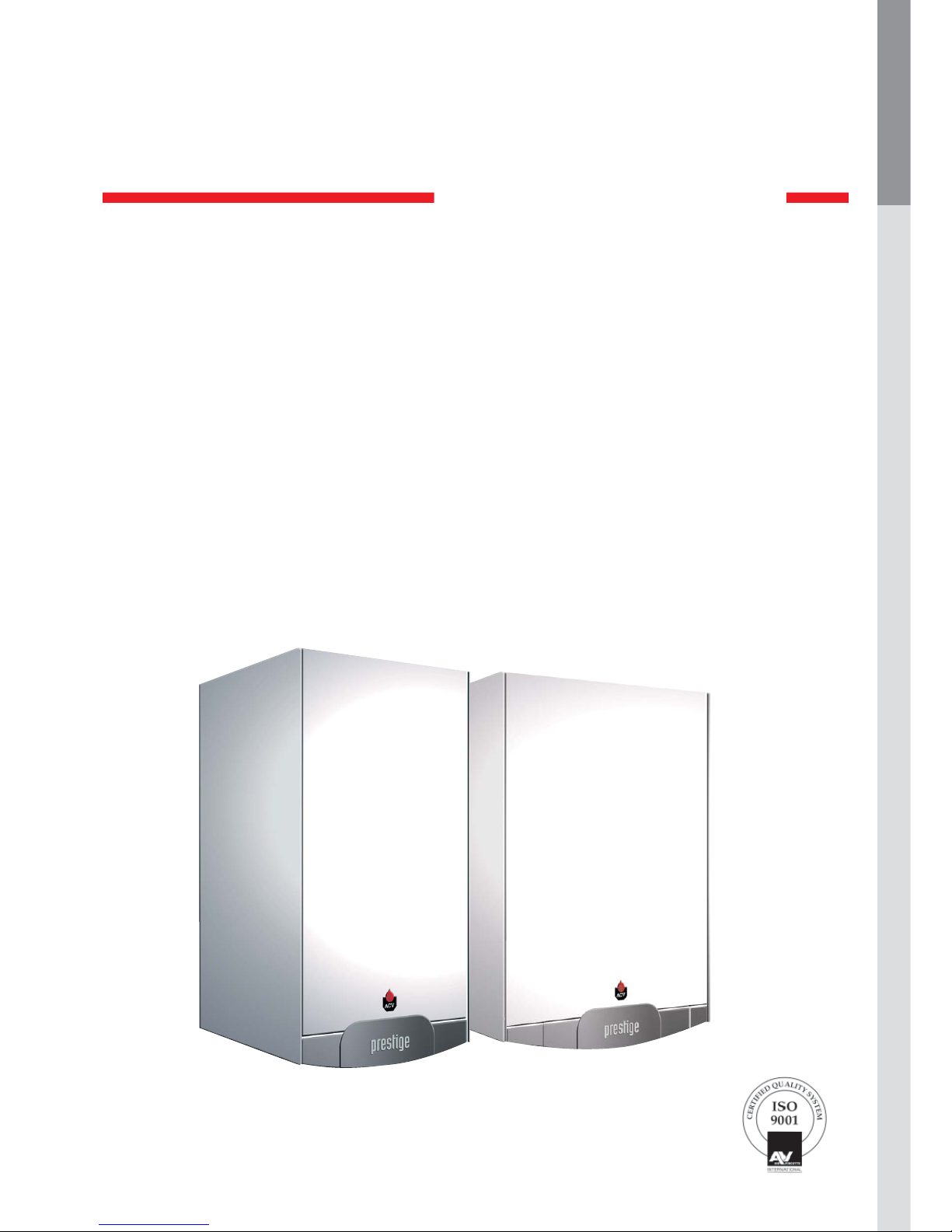
Installation, Operating and
Servicing Instructions
Prestige Solo 24 - 32
Prestige AquaSpeed 24 - 32
Prestige Excellence 24 - 32
Prestige
MK2
Page 2

EN • 2
ENGLISHFRANCAISNEDERLANDSESPAÑOLITALIANODEUTSCH
WARNING 3
Who should read these instructions 3
Symbols 3
Recommendations 3
Applicable standards 3
Warnings 3
INTRODUCTION 4
Description of the specifications 4
USERS GUIDE 6
Directions for use 6
Settings the parameters 6
TECHNICAL CHARACTERISTICS 7
Natural gas model 8
Propane model 8
Natural gas categories 9
Propane categories 9
Diagrams of the pressure drops 9
Domestic hot water features 9
INSTALLATION INSTRUCTIONS 10
Dimensions 10
Boiler room 10
Wall mounting of the boiler 10
Distances of hydraulic connections 11
INSTALLATION 12
Connection to the chimney 12
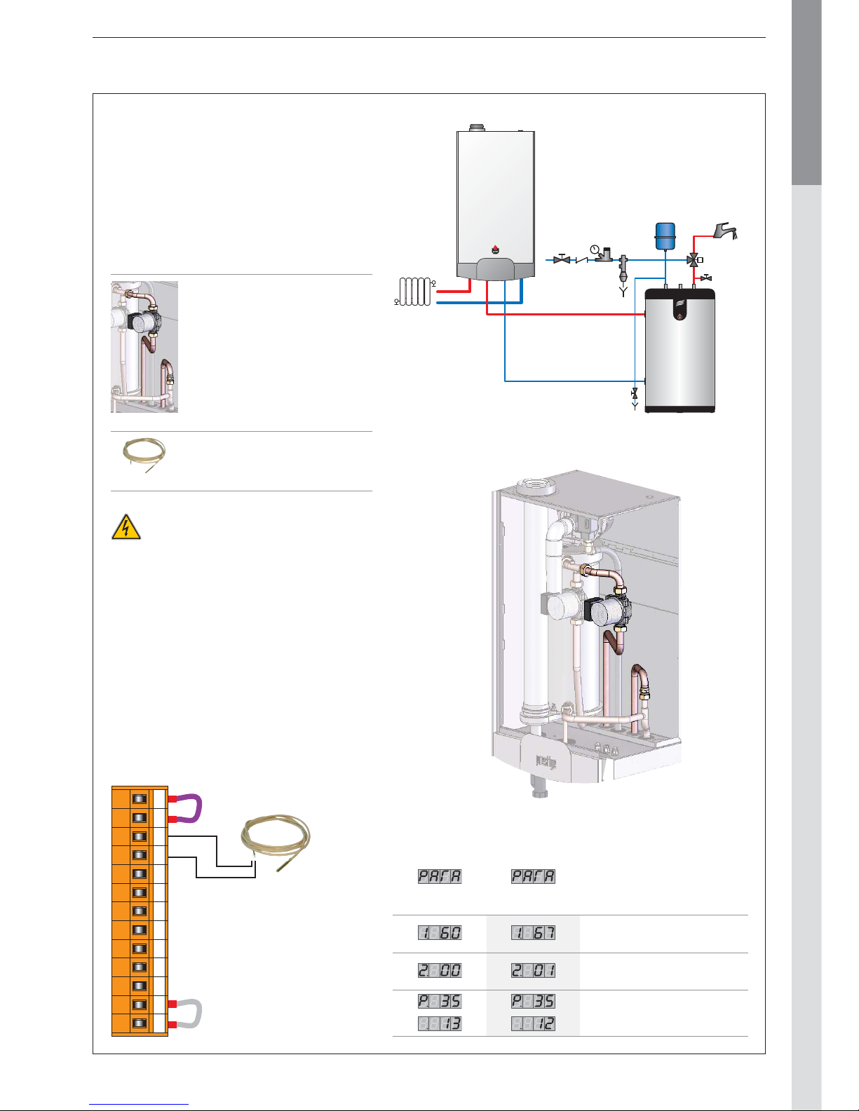
Domestic hot water connection : Prestige Solo 13
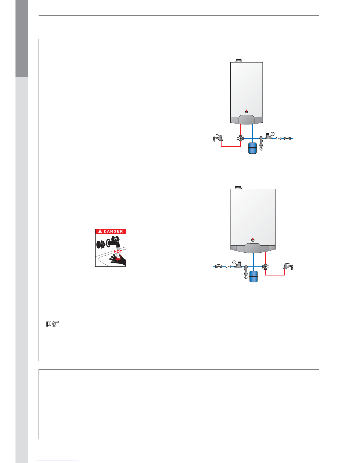
Domestic hot water connection : Prestige AquaSpeed / Excellence 14
Connection to the gas 14
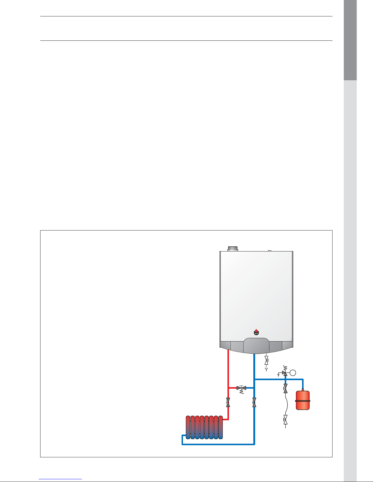
Heating connections 15
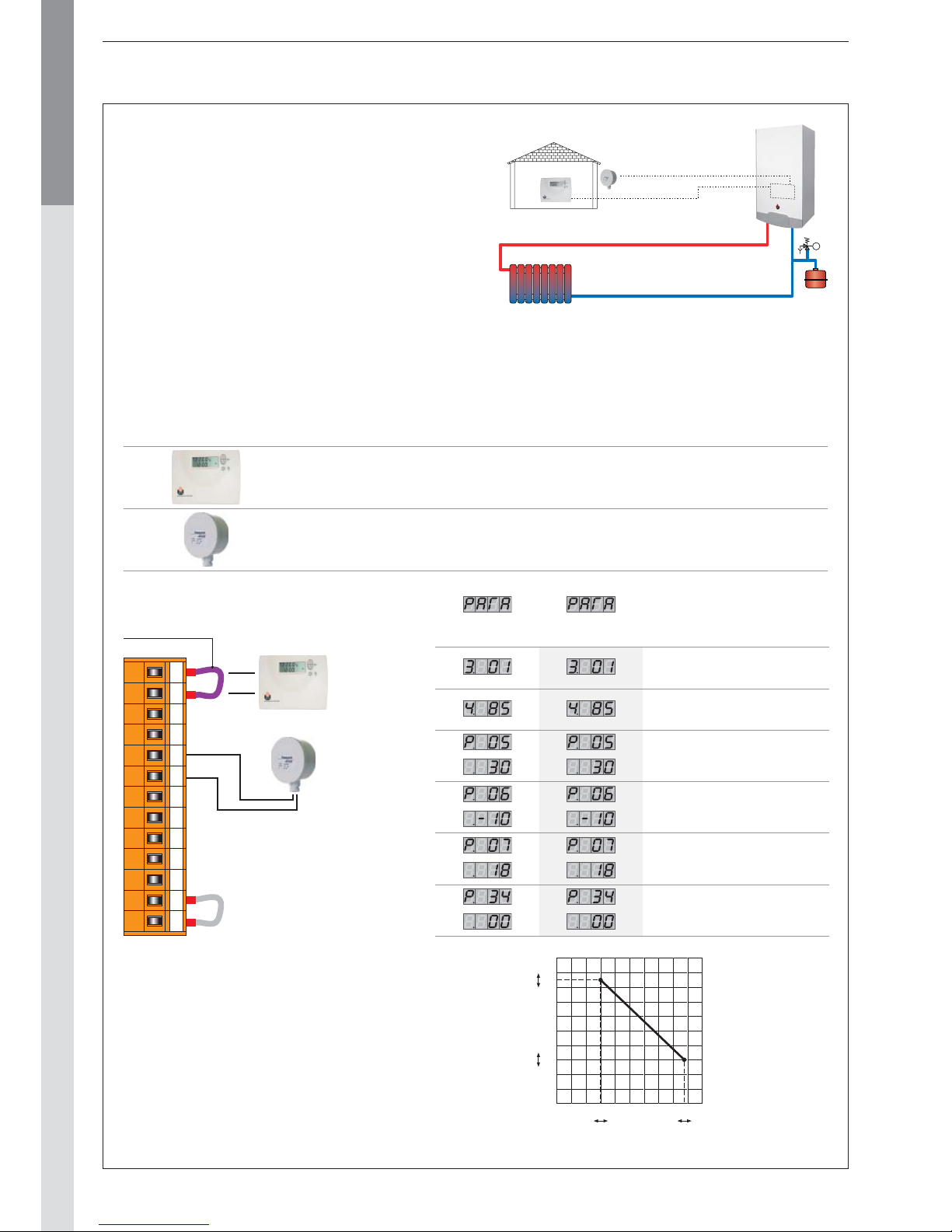
Installation of simple heating circuit controlled by room thermostat ACV 15 16
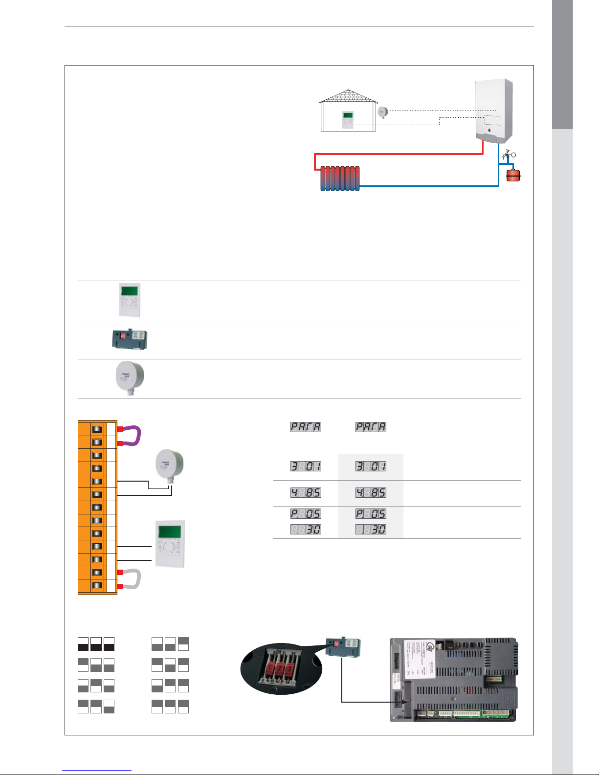
Installation of simple heating circuit controlled by Room Unit 17
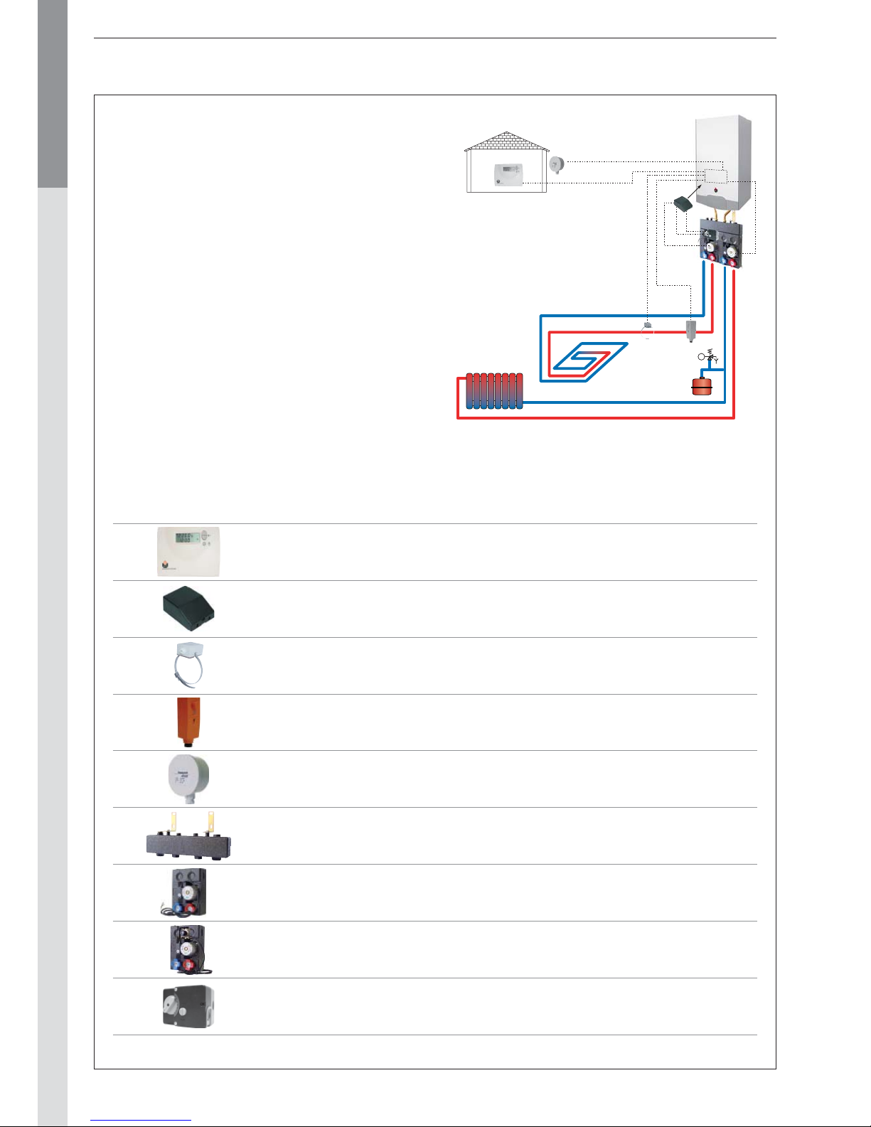
Installation of two heating circuits controlled by room thermostat ACV 15 and AM3-11 module 18
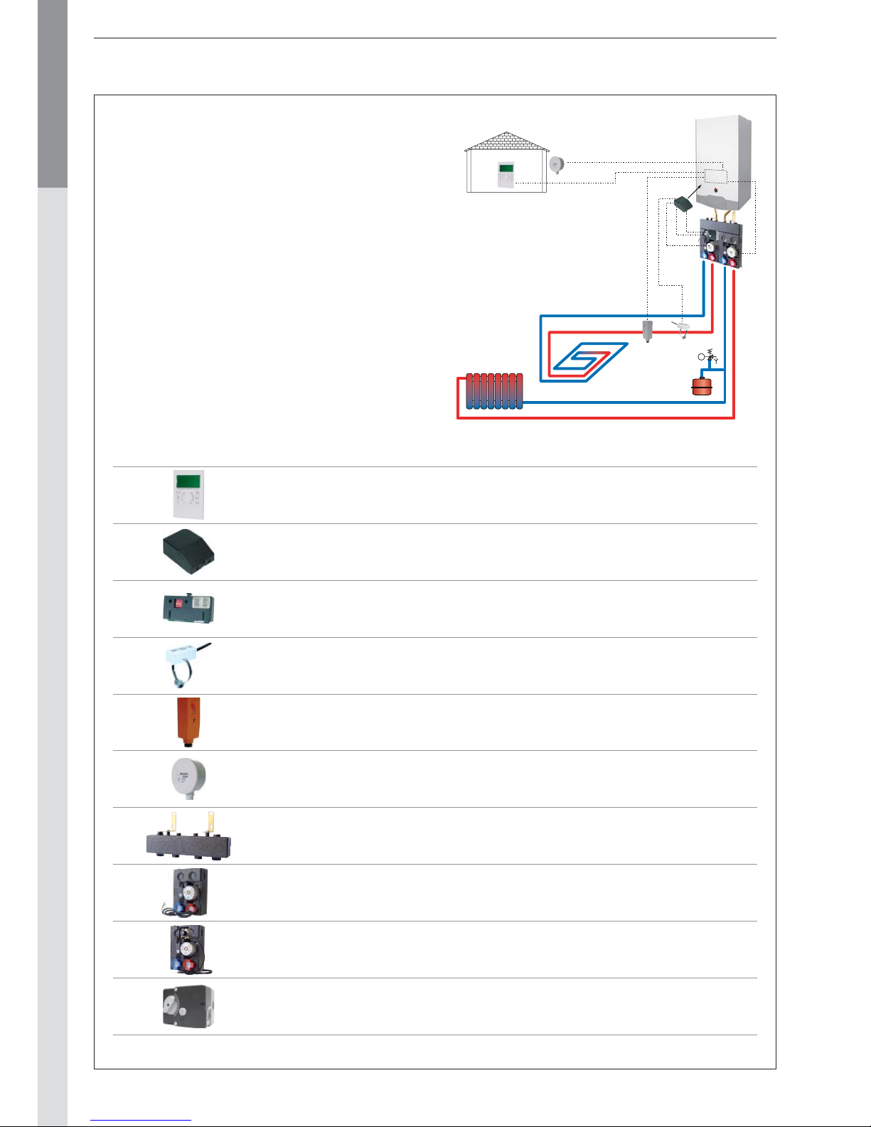
Installation of two heating circuits controlled by Room Unit and ZMC-1 module 20
ELECTRICAL CONNECTION 22
Wiring diagram : Prestige Solo / AquaSpeed / Excellence 22
COMMISSIONING AND MAINTENANCE 23
Commissioning the system 23
Inspection and maintenance 23
Disassembling the burner 24
Disassembling and checking the electrode 24
Disassembling the heat exchanger 24
AquaSpeed : Disassembling the inverted tank 24
Cleaning the heat exchanger 24
Temperature sensor resistance tables 24
MCBA PARAMETERS FOR THE SPECIALIST 25
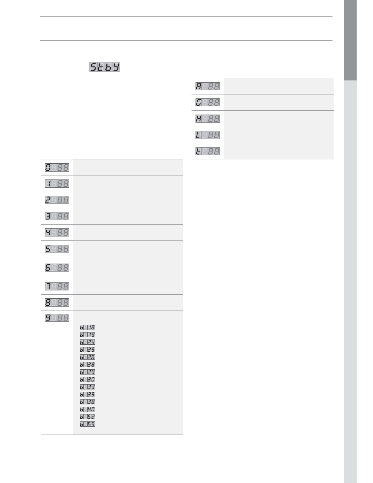
Standby Mode 25
Settings the MCBA parameters 26
Request for information on the installation 27
Entering the code 27
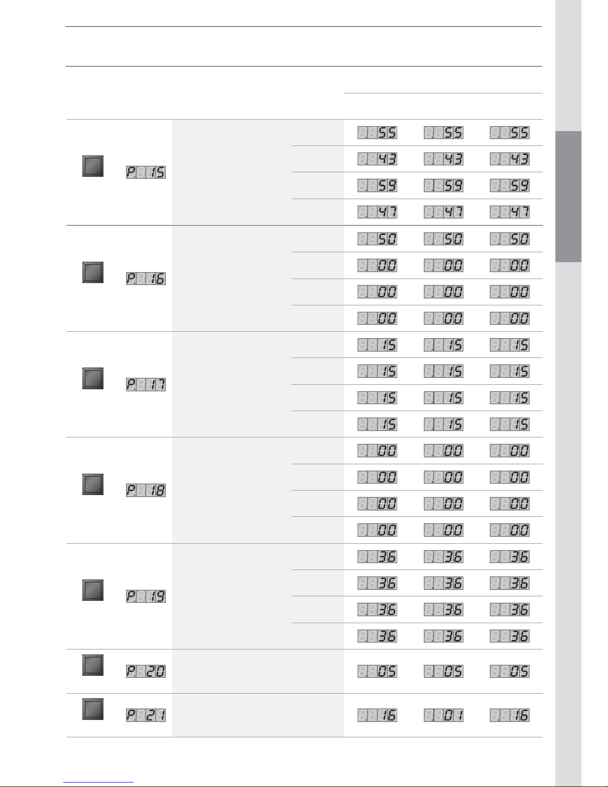
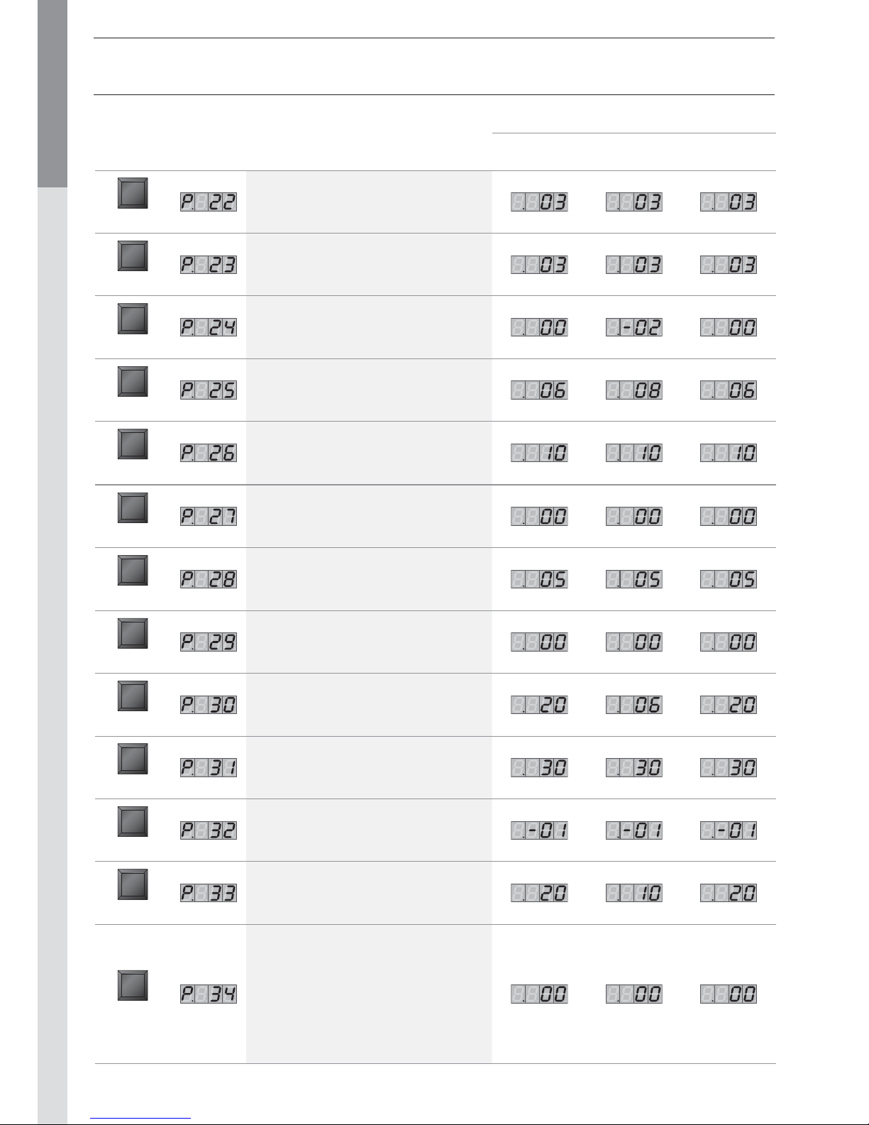
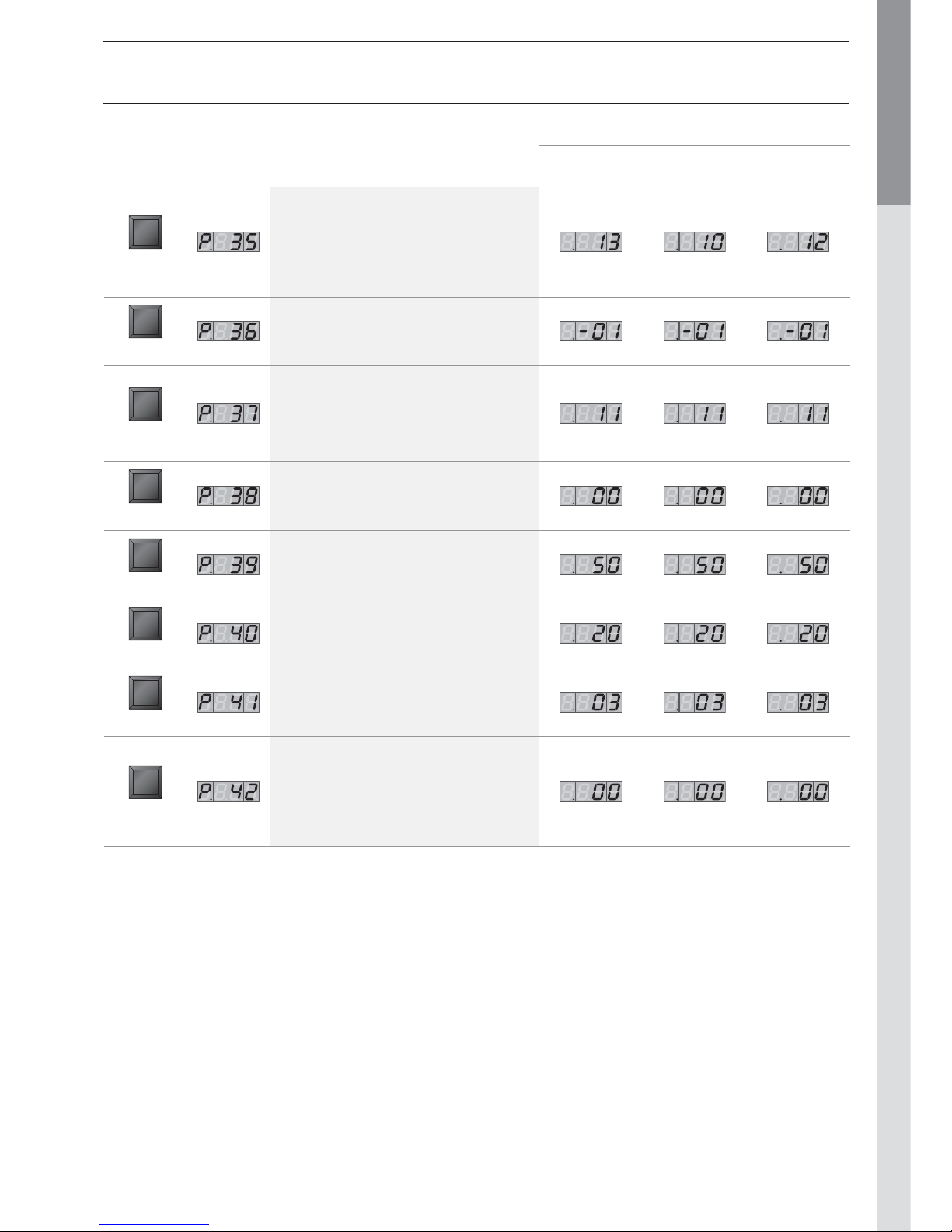
MCBA parameters with code restricted access 28
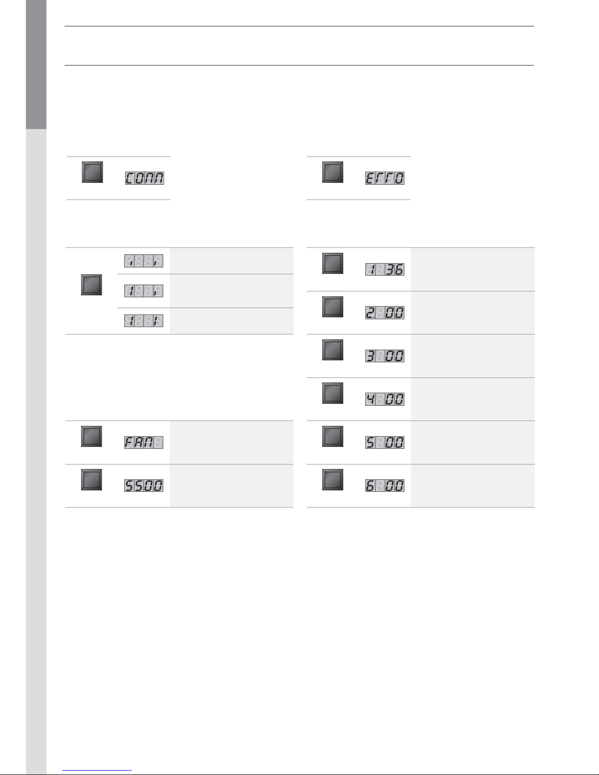
Communication Mode 32
Error Mode 32
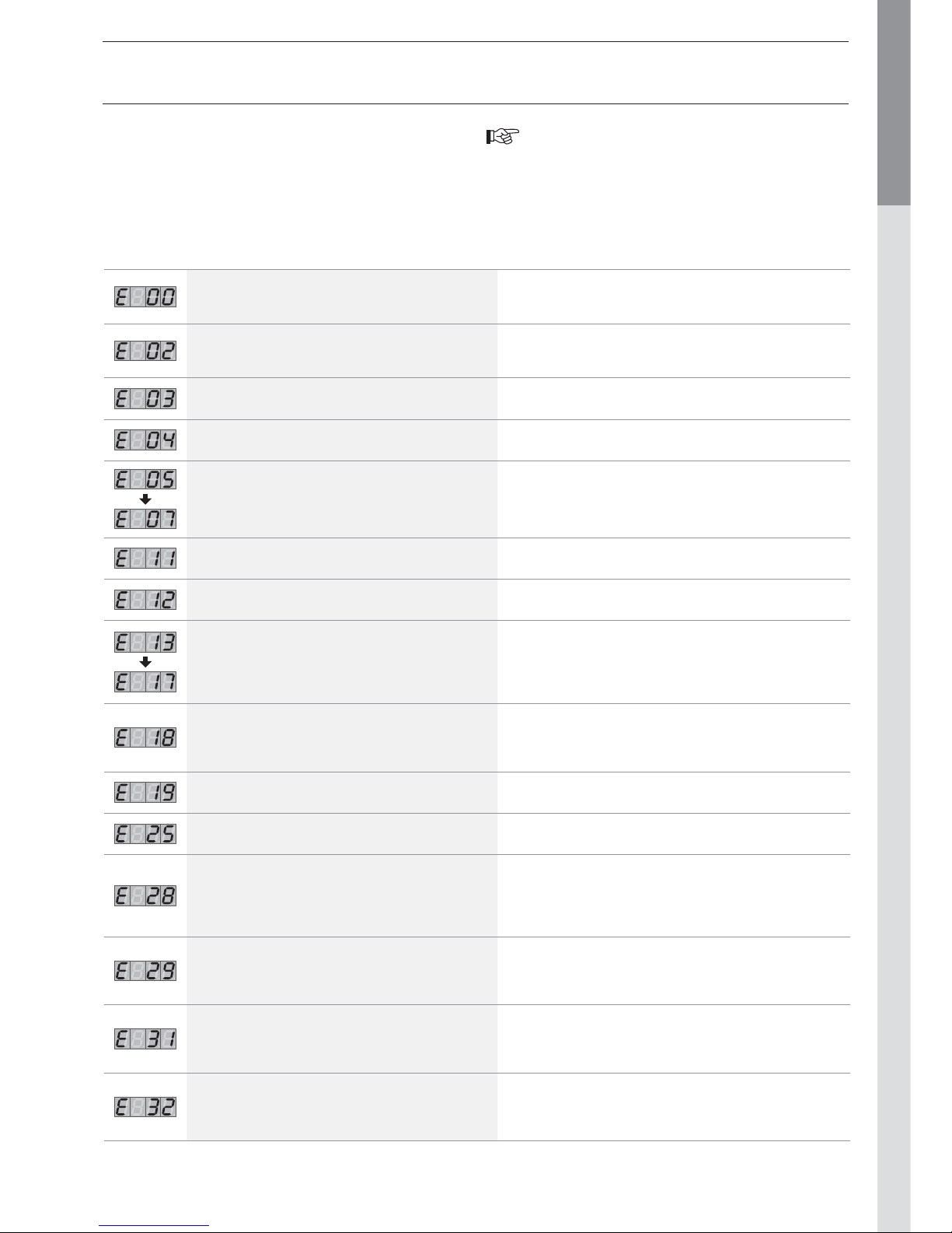
Safety stop + resolution of the fault 33
SPARE PARTS See at the end of this manual
INDEX
Page 3
EN • 3
ENGLISHFRANCAISNEDERLANDSESPAÑOLITALIANODEUTSCH
WHO SHOULD READ THESE INSTRUCTIONS
These instructions should be read by:
- the specifying engineer
- the installer
- the user
- the service engineer
SYMBOLS
The following symbols are used in this manual:
• The parts may only be replaced by genuine factory parts. You
will find a list of the spare parts and their reference number
ACV to the end of this document.
• The burners are preset in our factory for use with natural
gas
[equivalent to G20].
• An ajustement of the CO2 is not allowed in Belgium I 2E(s)B.
• It is important to switch the boiler off before carrying out
any work.
• There are no user accessible parts inside the boiler casing.
APPLICABLE STANDARDS
The appliances carry the CE mark in accordance with the
standards in force in the various countries (European Directives
92/42/EC “Efficiency”, 90/396/EC “Gas appliances”). They
also carry the “HR-TOP” label (Gas condensation boilers).
WAR NINGS
IF YOU SMELL GAS:
- Immediately shut off the gas intake
- Open windows for fresh air flowing
- Do not use any electrical appliances and do not actuate any
switches
- Immediately notify your gas supplier and/or your installer
This documentation is part of the information delivered with the
appliance and must be given to the user and stored in a safe
place!
An approved installer must carry out the assembly, commissioning,
maintenance and repair of the system, in accordance with current
standards in force.
ACV shall not accept any responsibility for damage caused by noncompliant location of the system or by use of the parts or
connections not approved by ACV for this application.
The manufacturer reserves the right to change the
technical characteristics and specification of its
products without notice.
The availability of some versions and their accessories is
market dependant.
WARNINGS
RECOMMENDATIONS
• Please, read carefully this manual before installing and
commissioning the boiler.
• It is prohibited to carry out any modifications to the inside of
the appliance without the manufacturer’s prior and written
agreement.
• The product must be installed and serviced by trained
engineers, in compliance with current standards.
• Any failure to follow instructions relating to tests and test
procedures may result in personal injury or risks of pollution.
• To guarantee safe and correct operation of the appliance, it
is important to have it serviced and maintained every year by
an approved installer or maintenance company.
• In case of anomaly, please call your service engineer.
• Despite the strict quality standards imposed by ACV during
the manufacture, inspection and transport of its appliances,
you might notice some errors. Please report immediately any
fault to your approved installer. Remember to note the fault
code displayed on the screen.
Danger of burns
Essential instruction for
the safety of persons
and the environment.
Danger of electrocution.
Essential instruction for
the correct operation of
the installation.
Page 4

EN • 4
ENGLISHFRANCAISNEDERLANDSESPAÑOLITALIANODEUTSCH
DESCRIPTION OF THE SPECIFICATIONS
The Prestige is a wall-mounted condensing boiler meeting
the requirements of the HR-Top applicable standards force in
Belgium. The boiler is certified compliant with EC standards as a
connected appliance C13(x), C33(x), C43(x), C53, C83(x), but it
can also be connected as an open appliance in category B23.
LINING
The boiler is protected by a steel lining that first of all undergoes a
degreasing and phosphation process before being lacquered and
heated at 220°C. The inside of this lining is coated with a layer of
thermal and acoustic insulation, reducing losses to a minimum.
HEAT EXCHANGER
The core of the Prestige features a new stainless steel heat
exchanger. This piece of technology represents the fruit of
exhaustive research and intensive laboratory testing. It reflects
ACV’s eighty years of experience in using stainless steel for
heating and hot water functions. The particular geometry of the
exchanger pipes is calculated to obtain a very large Reynolds
number throughout its cycles.
The Prestige achieves an exceptional output that remains stable
throughout the boiler’s life, given that it causes no oxidation on
the exchanger, which is manufactured entirely from quality steel.
BURNER
ACV uses its BG 2000-M burner for the Prestige: this is an
air/gas premix burner providing safe and silent operation while
limiting emissions (NOx and CO) to an incredibly low level. Although
the ACV BG 2000-M boiler is very modern, it uses proven
technology and is manufactured from standard spare parts that
are easily available on the market.
TEMPERATURE REGULATION
The basic version of the Prestige is fitted with a microprocessor
controlled regulator (MCBA) which takes over both the
safety functions (ignition, monitoring the flame, limiting the
temperature, etc.) and control of the boiler temperature.
This MCBA also includes a weather-dependent regulator. All
you need to do is connect the ou tdoor temperature sensor
available as an option to the device. However, this regulator
can also operate with a standard on/off room thermostat
In addition, with the combination of a weather-dependent
regulator and a room thermostat, you can control the temperatures based on the weather with compensation for the indoor
temperature.
There are four user adjustable parameters. By entering a
special maint enance code, qualified installers can access
several other parameters to adapt the boiler to special
requirements. In principle, these parameters are factory set
for all normal applications.
PRODUCTION OF HOT WATER
• Prestige Solo: is custom-designed to operate for heating
only or in combination with the whole range of ACV water tanks.
The SmartLine range is the number one choice for domestic
applications. To simplify the installation of such a combination,
ACV has designed a specific hot water connection kit, easy to
be incorporated inside the casing.
• Prestige AquaSpeed: has a constant supply of hot water
from its 6-litre tank that is directly and immediately available.
It combines all the advantages of hot-water storage and
immediate production: instant hot water, without the need
for additional hot water storage. The Prestige 32 AquaSpeed
provides 13.3 litres of hot water per minute at 40°C, instantly
and without waste (ΔT 30°C). The AquaSpeed mini tank is
made of stainless steel and the hot water is heated by means
of a copper coil in the tank.
• Prestige Excellence: combines all the advantages of
ACV’s Tank-in-Tank systems with the comfort and space
saving of a wall-mounted boiler: in a 63 cm wide casing, it
includes a 62-litre stainless steel Tank-in-Tank. The Prestige
32 Excellence supplies 258 litres of water at a temperature
of 40°C in 10 minutes: In addition to their exceptional hot
water supply capability, the Prestige Excellence tank-in-tanks
feature:
- A solution for scale deposits: thanks to the specially designed
corrugations, the hot water tank expands and contracts during
the heating cycle, preventing the formation of scale.
- A guarantee against the risk of Legionnellae Disease and
bacteria: the hot water tank is fully immersed in the primary
circuit and the hot water is constantly kept at a temperature
above 60°C.
- Exceptional resistance against corrosion and aggression:
provided by the stainless steel.
FROST PROTECTION
The boiler is equipped with an integrated frost protection: as
soon as the NTC1 flow temperature drops below 7°C, the system
activates the central heating pump. As soon as the NTC1 flow
temperature drops below 3°C, the system automatically ignites
the burner until the temperature rises above 10°C. The pump
continues to run for about 10 minutes.
If an outdoor temperature sensor is connected to the system,
the pump is activated as soon as the outside temperature drops
below the specified threshold.
To provide efficient protection for the whole system, all valves of
the valves on the radiators and the convectors should be completely open.
INTRODUCTION
Page 5
EN • 5
ENGLISHFRANCAISNEDERLANDSESPAÑOLITALIANODEUTSCH
INTRODUCTION
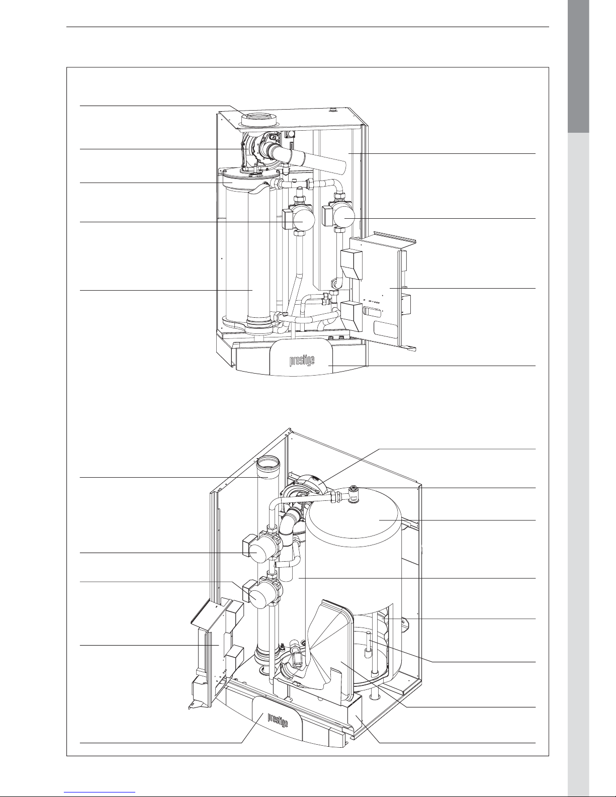
Chimney connection
[concentric tubes Ø 80/125 mm]
Tappot 6 litres
[not available on Prestige Solo]
Pump, Domestic Hot Water
Electrical panel
[The control boxes on
the rear are optional]
Heat exchanger, stainless steel
Pump, central heating
Burner, premix and modulating
Flue tube
Control panel
PRESTIGE AQUASPEED
Flue tube
[concentric tubes Ø 80/125 mm]
Pump, Domestic Hot Water
Electrical panel
[The control boxes on
the rear are optional]
Control panel
Expansion vessel
[depend of countries]
Bracket for expansion vessel
Water heater 62 litres
Pump, central heating
Heat exchanger, stainless steel
Burner, premix
and modulating
Hot water storage tank,
stainless steel
Drywell for DHW sensor
PRESTIGE EXCELLENCE
Manual air vent
Page 6
EN • 6
ENGLISHFRANCAISNEDERLANDSESPAÑOLITALIANODEUTSCH
DIRECTIONS FOR USE
Your system must be checked once a year by an approved
installer or maintenance company.
Starting the burner
During operation, the burner starts automatically as soon as
the boiler temperature drops under the required set point and
it stops as soon as the boiler reaches that temperature.
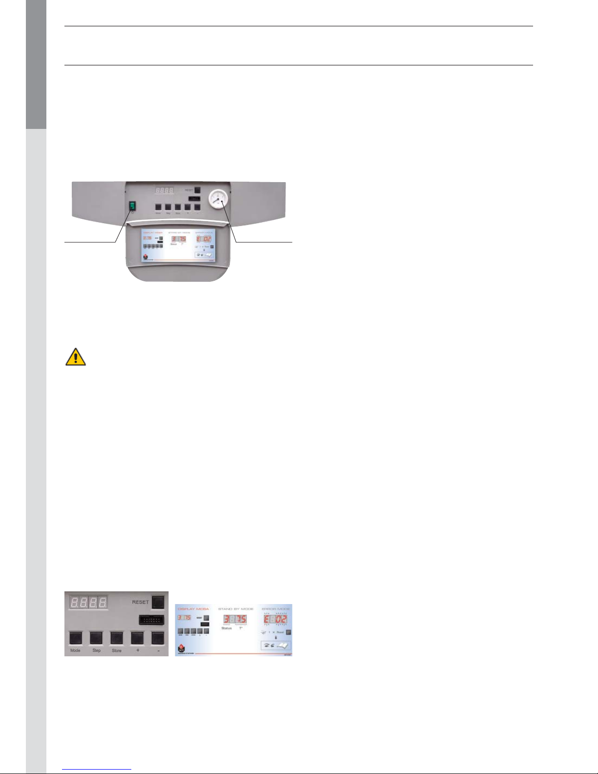
Control panel
Heating system
The central heating cir cuit must be pressurized (see in the
chapter “Installation” how to define the system pressure).
The pressure indicator is located on the right-hand side of the
display.
If your system needs to be refilled more than twice
a year, please contact your installer.
The CH pressure must be a minimum of 1 bar and must be
checked by the end user on a regular basis. If the pressure
drops under 0.5 bar, the integrated water pressure switch
blocks the appliance until the pressure in the system returns
to a level above 0.8 bar. The connection for a fill valve is
provided underneath the appliance. The installer can also fit
the system with a separate valve. Make sure that the appliance
is powered off when filling the sys tem. TTo do this, toggle the
Star t/Stop switch located on the left of the screen to Of f. (see
the Control panel).
For more information, please ask your installer when the system
is delivered.
A safety valve is provided at the underneath of the appliance.
If the system pressure exceeds 3 bars, this valve opens and
drains the water from the system. In this case, please contact
your installer.
SETTING THE PARAMETERS
Setting the domestic hot water temperature
(Hot water temperature)
- Press Mode: The screen displays PA RA.
- Press Step: the first character is 1 and the las t two characters
give the current hot water temperature setting.
- To change this temperature, press + or - until the last two
digits show the desired temperature value.
- Press Store to save the new temperature setting.
- Press Mode twice to return to Pilot mode (normal operating
mode).
Enabling or disabling the hot water heating mode
(hot water)
- Press Mode: The screen displays PA RA.
- Press Step twice: the first character is 2 and the last two
characters give the current setting:
00 = disabled; 01 = enabled.
- To change this parameter, press + or - until the screen
displays the desired value:
00 = disabled; 01 = enabled.
- Press Store to save.
- Press Mode twice to return to Pilot mode (normal operating
mode).
Enabling or disabling Central Heating mode:
(heating)
- Press Mode: The screen displays PARA.
- Press Step three times: the first character is 3 and the last
two characters give the current setting:
00 = disabled; 01 = enabled.
- To change this parameter, press + or - until the screen
displays the desired value:
00 = disabled; 01 = enabled.
- Press Store to save.
- Press Mode twice to return to Pilot mode (normal operating
mode).
Setting the central heating temperature:
(maximum temperature for the heating circuit)
- Press Mode: The screen displays PA RA.
- Press Step four times: the first character is 4 and the last
two charac ters give the current central heating temperature
setting.
- To change this temperature, press + or - until the last two
digits show the desired temperature value.
- Press Store to save the new temperature setting.
- Press Mode twice to return to Pilot mode (normal operating
mode).
Fault:
The temperature setting for the appliance and the safety
functions for its various parts are continuously monitored by
a regulator controlled by a microprocessor (the MCBA). In the
event of a faul t, this MCBA disables the appliance and displays
an error code: the screen flashes displaying E as the first
character, followed by the error code.
To reset the appliance:
- Press "Reset" on the screen.
- Contact your installer of the fault happens again.
USERS GUIDE
Start/Stop
switch
Pressure
gauge
Also see the user label located inside the valve on the control
panel:
Page 7

EN • 7
ENGLISHFRANCAISNEDERLANDSESPAÑOLITALIANODEUTSCH
TECHNICAL CHARACTERISTICS
NATURAL GAS MODEL
Solo AquaSpeed Excellence
Central heating 24 32 24 32 24 32
Max. Input 80/60°C
kW
24 32 24 32 24 32
Min. Input 80/60°C
kW
5,9 5,9 5,9 5,9 5,9 5,9
Max. output 80/60°C
kW
23,4 31 23,4 31 23,4 31
Min. output 80/60°C
kW
5,8 5,8 5,8 5,8 5,8 5,8
Effi ciency 30% load [EN677]
%
109 109 109 109 109 109
Flue gases
CO emissions max. / min. Input
mg/kWh
45 / 20 52 / 20 45 / 20 52 / 20 45 / 20 52 / 20
NOx emissions [EN483]
mg/kWh
66 66 66 66 66 66
NOx classifi cation [EN483] 5 5 5 5 5 5
Flue gas temperature — max. Input 80/60°C
°C
70 76 70 76 70 76
Flue gas temperature — max. Input 50/30°C
°C
37 39 37 39 37 39
Mass fl ow rate of combustion products
kg/h
38 52 38 52 38 52
Flue gas pipe - Max. pressure drop
Pa
130 130 130 130 130 130
Concentric fl ue gas channel maximum length Ø 80 / 125 mm
m
20 20 20 20 20 20
Gas
Category [varies by country] I 2E[S]B — I 2Er — I 2H — I 2ELL — I 2L — I 2E
Gas pressure
mbar
20/25 20/25 20/25 20/25 20/25 20/25
G20 gas fl ow rate
m
3
/h
2,5 3,4 2,5 3,4 2,5 3,4
G25 gas fl ow rate
m
3
/h
3,0 3,9 3,0 3,9 3,0 3,9
CO
2
max. Input G20/25 (with front panel closed)
% CO
2
9,3 9,3 9,3 9,3 9,3 9,3
CO
2
max. Input G20/25 (with front panel open)
% CO
2
9,0 9,0 9,0 9,0 9,0 9,0
CO
2
min. Input G20/25 (with front panel closed)
% CO
2
9,2 9,2 9,2 9,2 9,2 9,2
Hydraulic parameters
Max. operating temperature
°C
90 90 90 90 90 90
Boiler water capacity
L
8 8 14 14 16 16
Domestic hot water circuit capacity
L
- - 0,9 0,9 54 54
Maximum operating pressure central heating
bar
333333
Heat exchanger pressure drop [ΔT = 20°C]
mbar
131 210 131 210 131 210
Capacity of the expansion vessel
(depend of countries)
L
- - - - 12 12
Electrical connection
Class
IP
30 30 30 30 30 30
Supply voltage
V/Hz
230 / 50 230 / 50 230 / 50 230 / 50 230 / 50 230 / 50
Maximum absorbed electrical power
A
0,8 0,8 1,2 1,2 1,2 1,2
Weight empty kg 48 48 63 63 92 92
Page 8

EN • 8
ENGLISHFRANCAISNEDERLANDSESPAÑOLITALIANODEUTSCH
TECHNICAL CHARACTERISTICS
PROPANE MODEL
Solo P AquaSpeed P Excellence P
Central heating 24 32 24 32 24 32
Max. Input 80/60°C
kW
24 30,5 24 30,5 24 30,5
Min. Input 80/60°C
kW
5,9 5,9 5,9 5,9 5,9 5,9
Max. output 80/60°C
kW
23,4 29,6 23,4 29,6 23,4 29,6
Min. output 80/60°C
kW
5,8 5,8 5,8 5,8 5,8 5,8
Effi ciency 30% load [EN677]
%
109 109 109 109 109 109
Flue gases
Flue gas pipe - Max. pressure drop
Pa
130 130 130 130 130 130
Concentric fl ue gas channel maximum length Ø 80 / 125 mm
m
20 20 20 20 20 20
Gas
Category [varies by country] I 3P
Gas pressure
mbar
30 / 37 / 50
G31 gas fl ow rate
m
3
/h
0,98 1,3 0,98 1,3 0,98 1,3
CO
2
max. Input G31 (with front panel closed)
% CO
2
11 11 11 11 11 11
CO
2
max. Input G31 (with front panel open)
% CO
2
10,7 10,7 10,7 10,7 10,7 10,7
CO
2
max. Input G31 (with front panel closed)
% CO
2
10,9 10,9 10,9 10,9 10,9 10,9
Hydraulic parameters
Max. operating temperature
°C
90 90 90 90 90 90
Boiler water capacity
L
8 8 14 14 16 16
Domestic hot water circuit capacity
L
- - 0,9 0,9 54 54
Maximum operating pressure central heating
bar
333333
Heat exchanger pressure drop [ΔT = 20°C]
mbar
131 210 131 210 131 210
Capacity of the expansion vessel
(depend of countries)
L
----1212
Electrical connection
Class
IP
30 30 30 30 30 30
Supply voltage
V/Hz
230 / 50 230 / 50 230 / 50 230 / 50 230 / 50 230 / 50
Maximum absorbed electrical power
A
0,8 0,8 1,2 1,2 1,2 1,2
Weight empty kg 48 48 63 63 92 92
Page 9
EN • 9
ENGLISHFRANCAISNEDERLANDSESPAÑOLITALIANODEUTSCH
TECHNICAL CHARACTERISTICS
DOMESTIC HOT WATER FEATURES
AquaSpeed Excellence
Operating conditions at 80°C 24 32 Operating conditions at 80°C 24 32
Flow at 40°C [ΔT = 30°C]
L/min.
11 14,5 Peak fl ow at 40°C [ΔT = 30°C]
L/10’
175 224
Flow at 60°C [ΔT = 50°C]
L/min.
6,6 8,3 Peak fl ow at 40°C [ΔT = 30°C]
L/60’
733 835
Constant fl ow at 40°C [ΔT = 30°C]
L/h
653 745
Peak fl ow atv 60°C [ΔT = 50°C]
L/10’
102 103
Peak fl ow at 60°C [ΔT = 50°C]
L/60’
352 353
Constant fl ow at 60°C [ΔT = 50°C]
L/h
316 320
Pre-heat time
minutes
27 25
Natural gas categories BE FR NL LU DE
AT - CH - CZ - DK - ES - IT - FI
UK - IE - PT - SE - GR - HU
I 2 E(S)B
G20 / 20 mbar – G25 / 25 mbar
I 2 Er
G20 / 20 mbar – G25 / 25 mbar
I 2 L
G25 / 25 mbar
I 2 E
G20 / 20 mbar
I 2 ELL
G20 / 20 mbar – G25 / 20 mbar
I 2 H
G20 / 20 mbar
Propane categories DK - NL - NO - IT
BE - CH - ES - FR - UK
IE - PT - FI - SE - IT - GR
AT - CH - CZ - ES
NL - DE - LU - HU
I 3 P
G31 / 30 mbar
I 3 P
G31 / 37 mbar
I 3 P
G31 / 50 mbar
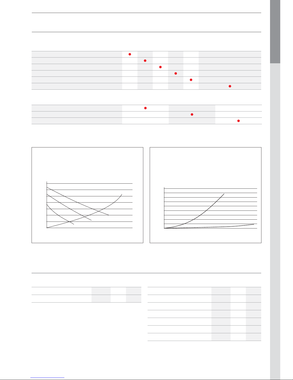
DIAGRAMS OF PRESSURES DROPS
Pressure drop on the domestic hot water side
0
0,2
0,4
0,6
0,8
1
1,2
1,4
1,6
1,8
0 5 10 15 20 25 30
Volume of domestic hot water (litres / minute)
Pressure drop (bar)
A
B
Pressure drop on the heating side
0
1
2
3
4
5
6
7
0 200 400 600 800 1000 1200 1400 1600 1800 2000 2200 2400
Flow (litres / hour)
Pressure (mH2O)
A
B
C
D
A = Pressure drop of the boiler
B = Pressure available (for the heating circuit) circulator on 1
C = Pressure available (for the heating circuit) circulator on 2
D = Pressure available (for the heating circuit) circulator on 3
A = Pressure drop on the domestic hot water side Prestige AquaSpeed
B = Pressure drop on the domestic hot water side Prestige Excellence
Page 10
EN • 10
ENGLISHFRANCAISNEDERLANDSESPAÑOLITALIANODEUTSCH
INSTALLATION INSTRUCTIONS
in.
300
mm
in. 22
0
mm
Min. 25 mm Min. 25 mm
prestige
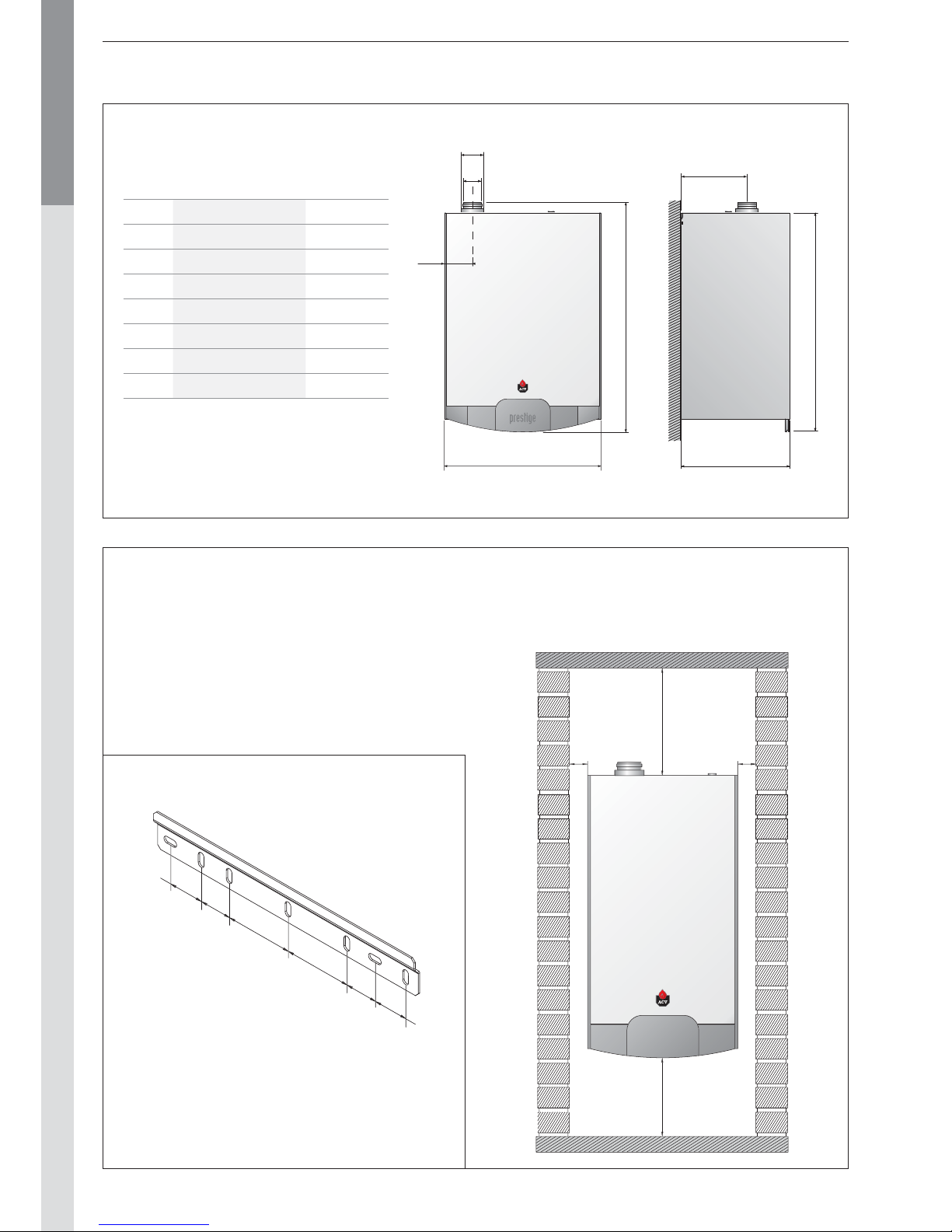
- The boiler must be mounted on a non-flammable wall.
- Drill two 10 mm diameter holes, spaced as indicated on
the above drawing.
- Secure the wall-mount bracket with the delivered anchor
screws.
- Hook the boiler on the bracket.
BOILER ROOM
- Make sure that all air vents are unobstructed any times.
- Do not store any flammable products in the boiler room.
- Do not store any corrosive products, paint, solvents, salts,
chlorine products and other detergent products near the
appliance.
- If you smell gas, do not switch on any lights, turn off the
gas tap at the meter, ventilate the rooms and contact your
installer.
101,6 m
m
53,2 m
m
53,2 m
m
48,4 m
m
WALL MOUNTING OF THE BOILER
A
BH
C
D
E
F
G
DIMENSIONS
Solo / AquaSpeed Excellence
A mm 970 1030
B mm 502 632
C mm 107 110
D mm 80 80
E mm 125 125
F mm 300 300
G mm 930 1000
H mm 400 535
ACCESSIBILITY
The appliance must be positioned in such a way to be
accessible any time. In addition, the following distances
are required around the appliance.
Page 11
EN • 11
ENGLISHFRANCAISNEDERLANDSESPAÑOLITALIANODEUTSCH
INSTALLATION INSTRUCTIONS
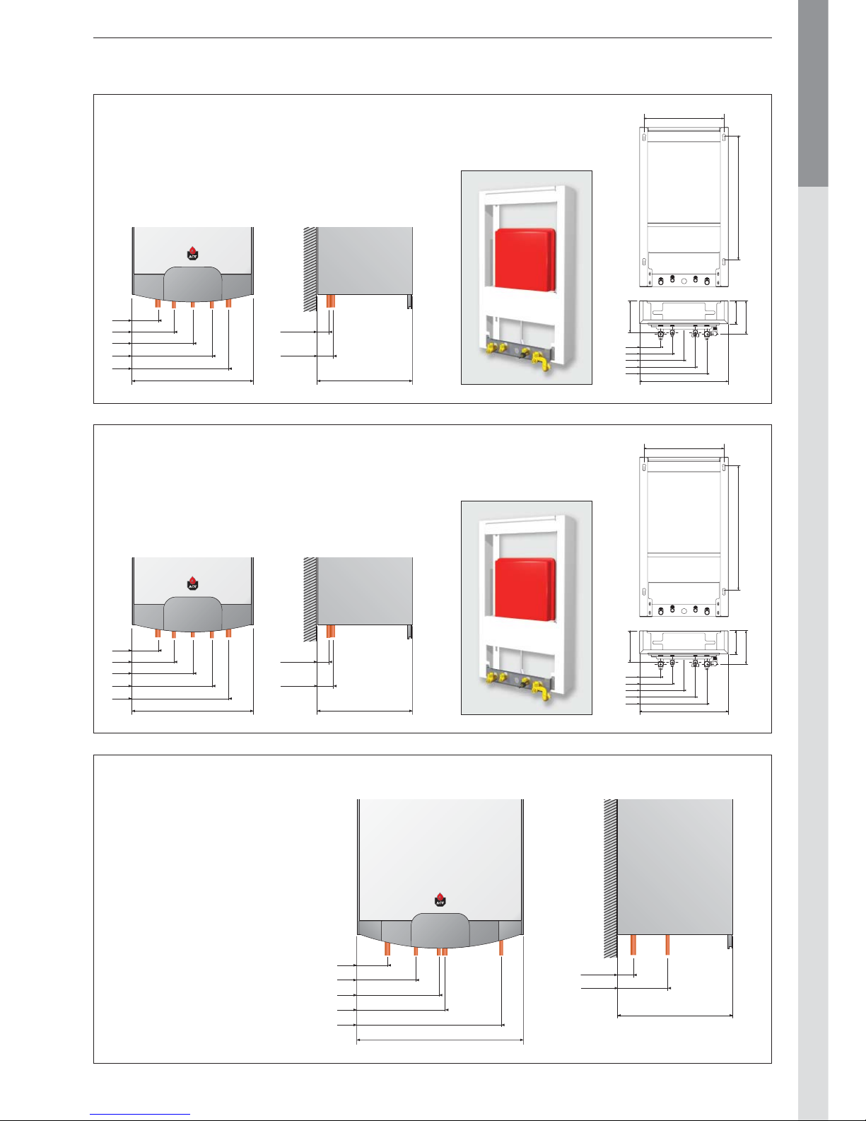
DISTANCES OF HYDRAULIC CONNECTIONS : SOLO
DISTANCES OF HYDRAULIC CONNECTIONS : AQUASPEED
DISTANCES OF HYDRAULIC CONNECTIONS : EXCELLENCE
70 0
450
179
120
169
502
A
C
E
D
B
120
185
250
315
380
400
59
49
A / B
C / D / E
502
A
C
E
120
185
250
D 315
B 380
prestige
A. CH supply 1” [F]
B. CH return 1” [F]
C. Domestic hot water supply 1/2” [M]
D. Cold water inlet 1/2” [M]
E. Gas connection 3/4” [M]
70 0
450
179
120
169
502
A
C
E
D
B
120
185
250
315
380
400
59
49
A / B
C / D / E
502
A
C
E
120
185
250
D 315
B 380
prestige
A. CH supply 1” [F]
B. CH return 1” [F]
C. Supply to the water heater 1” [F] -
With Kit DHW 10800079
D. Return from the water heater 1” [F] - with Kit DHW 10800079
E. Gas connection 3/4” [M]
535
206
61
C / D
A / B / E
A. CH supply 1” [F]
B. CH return 1” [F]
C. Domestic hot water supply 3/4” [M]
D. Cold water inlet 3/4” [M]
E. Gas connection 3/4” [M]
prestige
632
AB94
E 224
D 345
354
C 545
Page 12
EN • 12
ENGLISHFRANCAISNEDERLANDSESPAÑOLITALIANODEUTSCH
INSTALLATION
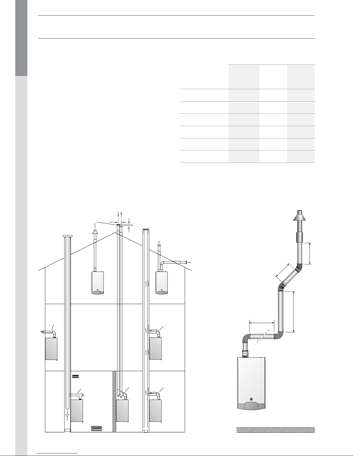
CONNECTION TO THE CHIMNEY
- The chimney connections must comply with the applicable
standards (in Belgium: NBN D51-003), the local energy
supplier’s instructions, the fire regulation and neighbourhood
good practices.
- The Prestige has an inbuilt gas/air ratio regulator, which makes
it largely independent of the pressure drop in the air intake and
flue gas extraction system. However, the maximum pressure
drop for this system may not be exceeded, or the pressure will
diminish. Nevertheless, the gas/air ratio regulator continuously
guarantees optimum combustion with very low emission levels.
- The horizontal flue gas pipes must always be installed with a
min. slope of 5 mm per meter, upwards from the boiler side.
- There must be no obstruction or openings for any other appliances within a radius of 0.5 metres around the flue terminal of
the Prestige.
- The maximum flue resistance is 130 Pascal. You can use the
following table as the basis for calculating this value (please also
refer to the specimen calculation presented under the table).
prestige
1000 mm
1000 mm
2000 mm
2000 mm
prestige prestige
C53
C33
150 min.
120
C13
B 23
C43
C43C33
Sample calculation:
The diagram below consists
of the following parts: pipe with
monitoring section + 2 * 90°
pipe bends + 2 metres of
horizontal pipe + 2 * 45° pipe
bends + (2 + 1 + 1) metres of
vertical pipe and fall back +
discharge.
Therefore, the resistance of this
system is as follows:
2.5 + (2 x 6.0) + (2 x 5.0) +
(2 x 4.0) + (4 x 5.0) + 20 =
72.5 Pa.
This value is less
than the maximum
authorised resistance,
therefore the
installation is
compliant.
Options for connection to the chimney
Table of flue resistance in Pascal
(1Pascal = 0,01 mbar)
Pipe
concentric
Ø 80/125
mm
Air inlet
separate
Ø 80
mm
Air extraction
separate
Ø 80
mm
1 m straight pipe
5.0 1.5 2.0
Pipe with a monitoring
section
2.5 — 1.0
90° pipe bend
6.0 1.9 3.4
45° pipe bend
4.0 1.3 2.3
Vertical pipe
20.0 — —
Horizontal pipe
15.0 — —
This table is based on the equipment offered by ACV and cannot be
applied generally.
Page 13
EN • 13
ENGLISHFRANCAISNEDERLANDSESPAÑOLITALIANODEUTSCH
Before any work on the boiler, it is important to
disconnect the power supply.
It is important to carry out all the electrical
connection before changing the MCBA parameters.
1. T h e 12 k Ω NTC sensor must be inserted into the
dywell and connected on terminals 3 and 4. (See
the picture below]
.
2. Connect the DHW pump to the dedicated
connector on the internal wiring (see the wiring
diagram]
.
INSTALLATION
DOMESTIC HOT WATER CONNECTION
PRESTIGE SOLO + SMART TANK
- Rinse the installation before connecting the
domestic hot water circuit.
- Fill the tank before filling the heating circuit.
prestige
12
4
5
6
7
3
Optional accessories
Code Description
10800079
Domestic hot water hydraulic kit
Kit to connect a Prestige Solo boiler to an
external water heater.
The kit includes :
- one circulator
- one NTC sensor 12kΩ (L = 3,2 m)
- one check valve
- three copper pipes + gaskets
5476G003
NTC sensor 12kΩ:
Senses the temperature in the external hot
water tank.
(Delivered with the kit 10800079)
1. Cold water supply tap
2. Non-return valve
3. Safety group
4. Pressure reducing valve
5. Hot water expansion vessel
6. Thermostatic mixer
7. Drawoff tap
factury
setting
typical
setting Description
Domestic hot water temperature
setting (to be adjusted between 60
and 80°C).
00 : DHW Mode “OFF”
01 : DHW Mode “ON”
12 : Tank with NTC sensor
13 : Tank with control thermostat
1 2 3 4 5 6 7 8 9 10 11 12 13
Page 14
EN • 14
ENGLISHFRANCAISNEDERLANDSESPAÑOLITALIANODEUTSCH
INSTALLATION
DOMESTIC HOT WATER CONNECTION
PRESTIGE AQUASPEED / EXCELLENCE
The Prestige Aquaspeed and Prestige Excellence boilers can
be connected directly on the domes tic hot water circuit.
Flush out the system before connecting the domestic hot
water part.
The installation must be fitted with an approved safety unit
with a 6-bar safety valve, a non-return valve and a shut-off
valve.
During the heating process, the domestic hot wat er dilates
and the pressure increases. As soon as the pressure exceeds
the safet y valve setting, the valve opens and discharges a
small quantity of water. Using a hot water expansion vessel
(2 litres at least) will prevent this phenomenon and reduce
water hammer effect.
Prestige AquaSpeed
If the flow demands become too high, the desired water
temperat ure will not be reached. To avoid this phenomenon,
we recommend that you place a flow limit er in the cold
water pipe just before the appliance.
Prestige Excellence
Drain the tank by opening a hot water tap.
Caution: the presence of air in the circuit usually causes
noisy air discharge effects.
The hot water output temperature may reach
temperatures in excess of 60°C, which can cause
burns. We therefore recommend that that you install
a thermostatic mixer immediately after installing the
appliance.
If stop valves are used in the domestic hot water
system, they can cause pressure waves when
closed. Use devices designed to reduce water
hammer to avoid this phenomenon.
1. Cold water supply tap
2. Non-return valve
3. Safety group
4. Pressure reducing valve
5. Hot water expansion vessel
6. Thermostatic mixer
7. Drawoff tap
CONNECTION TO THE GAS
- The Prestige is fit ted with a 3/4” male fit ting connector,
on which you can connect the gas tap.
- You must comply with the applicable regulations (e.g. NBN
D51-003) for gas connections, and the other standards
in force in the country of installation.
- Where there is a risk of dirt stemming from the network,
place a gas filter upstream from the connection.
- Drain the gas pipe and check in minut e detail that all the
boiler pipes, both inside and outside, are sealed.
- Check the gas pressure in the system. Consult the technical
characteristics.
- Check the gas pressure and consumption when commissioning
the appliance.
Prestige AquaSpeed
prestige
12
4
5
6
7
3
prestige
12
4
5
6
7
3
Prestige Excellence
Page 15
EN • 15
ENGLISHFRANCAISNEDERLANDSESPAÑOLITALIANODEUTSCH
HEATING CONNECTIONS : GENERAL
1. By-pass with differential pressure valve
2. Isolating valve, heating system
3. Safety valve calibrated to 3 bar, with pressure gauge
4. System filling valve
5. Expansion vessel
6. Drain cock
INSTALLATION
HEATING CONNECTIONS
Recommendations
- The central heating system must be completely flushed out
with tap water before connecting the boiler.
- Install the automatic air vent on the t op of the appliance
(Prestige AquaSpeed only). You will find this in the polyst yrene
packing.
- The device must be levelled, using the provided bracket, or
the optional wall frame
(not available for the Prestige Excellence) .
- The operating noise can be increased if the appliance is fitted
against a wall made of wood or other lightweight construction.
Using rubber absorbers can reduce this effect.
- The connections to the central heating system and the
domestic hot water system are provided with nuts. This
simplifies the assembly with the optional wall frames. If you
do not use the wall frames, then you must use flat connection
type fittings with flat gaskets.
- The central heating safety valve is incorporated under the
appliance and must be routed to the drain with an open
onnection (to allow inspection).
- The central heating pump is located inside the appliance.
You can change it s speed using the three position switch,
depending on needs or if the pipes are noisy.
- The wall frames of the Prestige AquaSpeed and Solo are
fitted with an integrated 12-litre expansion vessel.
Country dependant, the Prestige Excellence is equipped with
a 12 litres expansion vessel.
This is sufficient for systems with a capacit y of approximately
120 litres for the central heating. For larger-capacity systems,
you can add a suitable expansion vessel to the AquaSpeed,
the Prestige Solo and the Prestige Excellence for the central
heating.
- Fill the system with fresh water. Contact your ACV representative
about the use of inhibitors.
- It is possible that the pumps are locked due to the presence
of residual water from tests completed on the appliance.
Therefore, we recommend that you unblock the pumps
before filling the appliance.
- You will find the connection for the filling valve and/or
drainage valve on the bot tom of the appliance. Fill the appliance
to a minimum pressure of one bar. Drain the whole system and
re-fill the appliance to a pressure of 1,5 bar.
- The system must be designed to ensure a continuous flow
in the central heating circuit. If this flow is not guaranteed,
for example if using thermostatic valves, you should install a
pressure-dependent bypass in the system.
- Fit the siphon, fill it with tap water and connect the hose to
the drain using a connection with an inspection section. Make
sure you prevent the freezing of the condensates.
prestige
1
22
4
5
6
3
Page 16
EN • 16
ENGLISHFRANCAISNEDERLANDSESPAÑOLITALIANODEUTSCH
INSTALLATION
INSTALLATION OF A SIMPLE HEATING CIRCUIT
CONTROLLED BY ROOM THERMOSTAT ACV 15
General diagram
The On/Off room thermostat controls the central heating
system (radiators or convectors).
If an outside temperature sensor is connected, the boiler
continuously adjusts its operating temperature depending on
the outside temperature.
The pump is powered as soon as the room thermostat
generates an heat demand.
Advantages for the user:
- Comfort
- Maximum Output
- Simplicity of the sys tem
AF120
ACV 15
MCBA
Optional accessories Code Description
10800018 Room themostat ACV 15
10510100 Outside temperature sensor 12kΩ — AF120
1 2 3 4 5 6 7 8 9 10 11 12 13
Remove this
bridge
Factory
setting
typical
setting Description
00 : Heating mode “OFF”
01 : Heating mode “ON”
Setting T° for the heating water
(adjustable between 30 and 85°C).
T° min. for the heating water
(adjustable between 15 and 60°C).
Minimum outside temperature
(adjustable between -20 and 10°C).
Maximum outside temperature
(adjustable between 15 and 25°C).
00 : Using a outside temperature
sensor and a room thermostat
90
80
70
60
50
40
30
20
10
0
-20-25 -10-15 0-5 1052015 25
P4
P5
P6 P7
Outside T° (°C)
T° departure boiler (°C)
Page 17
EN • 17
ENGLISHFRANCAISNEDERLANDSESPAÑOLITALIANODEUTSCH
INSTALLATION
INSTALLATION OF A SIMPLE HEATING CIRCUIT
CONTROLLED BY ROOM UNIT
General diagram
A Room Unit controls the heating system (radiat ors or
convectors). The unit allows the selection various central
heating functions and can be programmed for up to 3
schedules per week, both for heating and hot water
production.
In this configuration, the boiler continuously ajusts its operating
temperat ure in function of the outside temperature.
AF120
MCBA
Room Unit
Optional accessories Code Description
10800034
Room Unit RSC
Delivered with outside temperature sensor
10800036
Clip-in interface RMCIEBV3
Activates the communication between the MCBA and the Room Unit RSC.
10510100 Outside temperature sensor 12kΩ — AF120
Factory
setting
typical
setting Description
00 : Heating mode “OFF”
01 : Heating mode “ON”
Setting T° for the heating water
(adjustable between 30 and 85°C).
T° min. for the heating water
(adjustable between 15 and 60°C).
Bus A
Bus B
1 2 3 4 5 6 7 8 9 10 11 12 13
10800036: Interface address “0”
= 7
= 6
= 5
= 4
= 3
= 2
= 1
= 0
Page 18
EN • 18
ENGLISHFRANCAISNEDERLANDSESPAÑOLITALIANODEUTSCH
INSTALLATION
INSTALLATION OF TWO HEATING CIRCUIT
CONTROLLED BY ROOM THERMOSTAT ACV 15
AND AM3-11 MODULE
General diagram
This is a simple way to control two heating circuits (radiators
or floor heating).
You can adjust those two circuits depending on the outside
temperature.
This is the ideal configuration for floor heating with additional
heating provided by radiators.
The floor heating temperature is adjusted on a first temperature
diagram, while the radiator loop follows a second temperature
diagram, if needed with a booster function.
AF120
ACV 15
MCBA
RAM
NTC12K
AM3 - 11
Optional accessories Code Description
10800018 Room thermostat ACV 15
10800095
AM3-11 module :
Controls the second heating circuit - communicates directly with the MCBA
537D3040
Contact sensor 12kΩ
To be mounted on the outlet of controlled circuit
10510900
Contact thermostat RAM 5109 :
Required to protect all fl oor heating circuits
10510100 Outside temperature sensor 12kΩ — AF120
10800077
Collector 2 circuits DN20 :
With bypass, connecting tubes and integrated wall brackets
10800097
High temperature kit DN20
Including: one circulation pump, two isolating valves, check valve, two thermometers
10800096
Low temperature kit DN20
Including: one circulation pump, two isolating valves, check valve, two thermometers, the
4-way valve with integrated bypass.
10800019
Servomotor SQK 349 :
Electromechanical servomotor SQK 349 for the three-way valve included in low temperature kit
(opening times : 150 seconds)
Page 19
EN • 19
ENGLISHFRANCAISNEDERLANDSESPAÑOLITALIANODEUTSCH
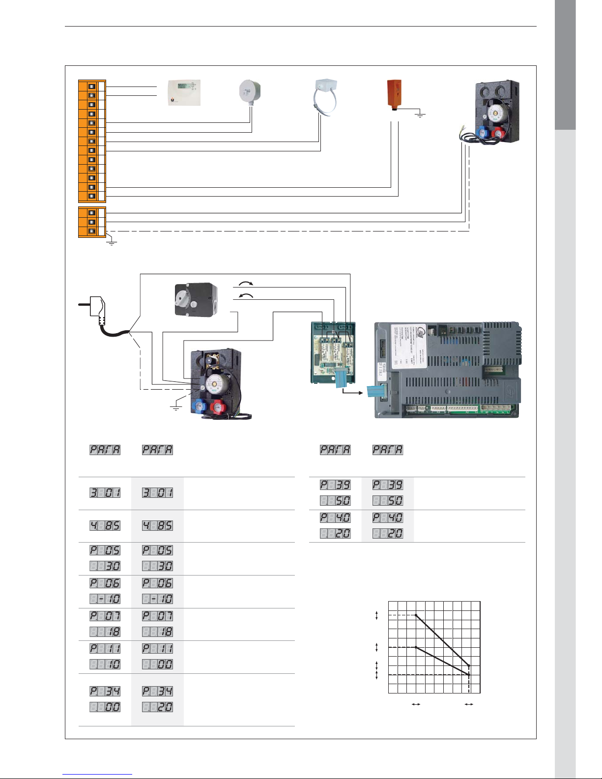
Factory
setting
typical
setting Description
Maximum temperature of the
second heating circuit
Minimum temperature of the second
heating circuit
Factory
setting
typical
setting Description
00 : Heating mode “OFF”
01 : Heating mode “ON”
Setting T° for the heating water
(adjustable between 30 and 85°C).
T° min. for the heating water
(adjustable between 15 and 60°C).
Minimum outside temperature [T4]
(adjustable between -20 and 10°C).
Maximum outside temperature [T4]
(adjustable between 15 and 25°C).
Booster
- The high T° circuit is controlled
depending on the outside T° and
the room thermostat.
- The low T° circuit is controlled
depending the outside T° only.
INSTALLATION
N
Y2
Y1
PhPE
NN
X1
X2
X3
21
L
L1
1 2 3 4 5 6 7 8 9 10 11 12 13 1 2 3
PE
Ph
N
To be wired in accordance with the applicable regulations.
90
80
70
60
50
40
30
20
10
0
-20-25 -10-15 0-5 1052015 25
P4
P39
P40
P5
P6 P7
Outside T° (°C)
T° departure boiler (°C)
Page 20
EN • 20
ENGLISHFRANCAISNEDERLANDSESPAÑOLITALIANODEUTSCH
INSTALLATION
INSTALLATION OF TWO HEATING CIRCUIT
CONTROLLED BY CONTROL UNIT AND
ZMC-1 MODULE
General diagram
This configuration controls two heating circuits (radiators
or floor heating). In addition, the Room unit features a
remote monitoring of the two circuits
You can adjust those two circuits depending on the out side
temperature.
This is the ideal configuration for floor heating with additional
heating provided by radiators.
You can select various heating functions, and program up
to three weekly schedules, as well for the central heating as
for the hot water production.
AF120
Room Unit
MCBA
RAM VF202
ZMC1
Optional accessories Code Description
10800034
Room Unit RSC
Supplied with outside temperature sensor
10800119
ZMC-1 module (kit) :
Controls the second heating circuit - alarm contact - operates only in conjonction with
the Room Unit RSC.
10800036
Clip-in interface RMCIEBV3
Enables communications between the MCBA and the Room Unit RSC.
10800045
Contact sensor 2kΩ — VF202 :
To be mounted on the outlet of controlled circuit
10510900
Contact thermostat RAM 5109 :
Required to protect all fl oor heating circuits
10510100 Outside temperature sensor 12kΩ — AF120
10800077
Collector 2 circuits DN20 :
With bypass, connecting tubes and integrated wall brackets
10800097
High temperature kit DN20
Including: one circulation pump, two isolating valves, check valve, two thermometers
10800096
Low temperature kit DN20
Including: one circulation pump, two isolating valves, check valve, two thermometers,
the 4-way valve with integrated bypass.
10800019
Servomotor SQK 349 :
Electromechanical servomotor SQK 349 for the three-way valve included in low
temperature kit
(opening times : 150 seconds)
Page 21
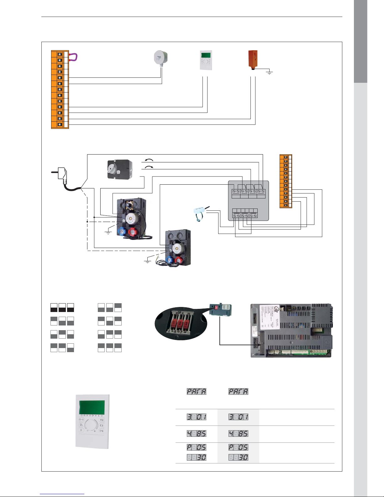
EN • 21
ENGLISHFRANCAISNEDERLANDSESPAÑOLITALIANODEUTSCH
INSTALLATION
21BA
1 2 3 4 5 6 7 8 9 10 11 12 13
AV MPK ZU AUF
0
24V
A B VF VE
ZMC1
N
Y1
Y2
PhPE
NN
1 2 3 4 5 6 7 8 9 10 11 12 13
B
A
10800036: Interface address “0”
= 7
= 6
= 5
= 4
= 3
= 2
= 1
= 0
To be wired in accordance with the applicable regulations.
Factory
setting
typical
setting Description
00 : Heating mode “OFF”
01 : Heating mode “ON”
Setting T° for the heating water
(adjustable between 30 and 85°C).
T° min. for the heating water
(adjustable between 15 and 60°C).
Hydraulic
parameter 6 = 23
Page 22
EN • 22
ENGLISHFRANCAISNEDERLANDSESPAÑOLITALIANODEUTSCH
ELECTRICAL CONNECTION
Type 3
230V
P
t
Br
B
Y/Gr
X11.
4
5
1
2
1 2 345
Br
B
BkRBk
W
Br
B
VV
WW
B
B
Or Or
V
B
RR Bk
Br
B
R
Bk
Br
RRB
G
G
R
Br Br
Or
V
Br
R
Bk
Br 11
10
9
8
7
6
5
4
3
13
12
2
1
Or
Bk B
Br
B
X12.1
X12.2
X12.3
B
B
R
B
B
B
B
G
G
X1.1
X10
X7
X1.2
X1.6
X1.4
X1.5
X1.3
X2.1
X2.2
X2.3
X2.4
X2.11
X2.12
X2.6
X2.8
X2.10
X2.9
X3.1
X3.2
X3.3
X3.5
X3.4
X4.1
X4.3
X4.2
X2.5
X5.1
X5.2
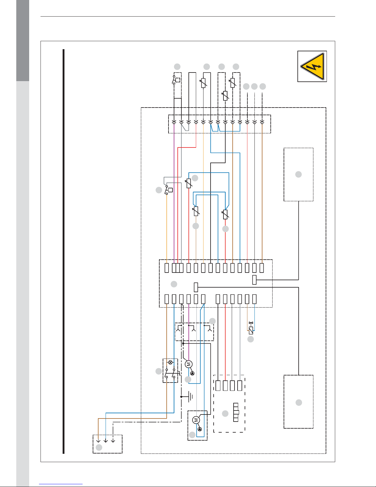
WIRING DIAGRAM : PRESTIGE 24-32 / Solo – AquaSpeed – Excellence
1. 230V connection cord
2. Start/Stop switch
3. Water tank charging pump socket
4. Heating pump
5. Burner
6. Gas valve
7. 230Volt - 24Volt transformer
8. MCBA
9. Screen
10. Water pressure switch
11. NTC1 flow sensor
12. NTC2 return sensor
13. NTC3 domestic hot
14. NTC5 flue gas temperature
15. Room thermostat (optional)
16. NTC4 outdoor temperature
17. NTC6 sensor for the circuit (optional)
18. Shell B (optional)
19. Shell A (optional)
20. Zero volt of 24V circuit.
21. Connection pumps (if two circuit)
B. Blue
Bk. Black
Br. Brown
G. Grey
Or. Orange
R. Red
V. Violet
W. White
Y/Gr. Yellow/Green
1
2
3
5
4
21
7
8
6
9
14
12
11
10
15
13
16
17
201819
Page 23
EN • 23
ENGLISHFRANCAISNEDERLANDSESPAÑOLITALIANODEUTSCH
COMMISSIONING AND MAINTENANCE
COMMISSIONING THE SYSTEM
- Slowly fill the tank and drain it by opening a hot water tap. Drain
all the taps and check that there are no leaks in the domestic
hot water system.
- Fill the whole system up to a minimum pressure of 1 bar
(preferably 1.5 bar), using the boiler’s fill valve. Fill the system
slowly and drain it using the central heating flow pipe manual
air vent. Also check that the automatic air vent (AquaSpeed)
on the tank is working. Check that there are no leaks in the
central heating system.
Prestige excellence: purge the primary circuit of the tank by
means of the manual air vent on the top of the tank.
- Purge the circulator(s)
- Open the gas valve, drain the pipe and check that there are no
leaks in the system.
- Check that the siphon is filled.
- Connect the plug to the wall socket and power on the appliance. If needed, place the room thermostat to its highest
position. The boiler should start. Check the gas pressure and
allow the boiler to heat up for a few minutes. Set the boiler
to High Power mode and check the CO2 level (see the table
of Technical Characteristics)
. Then, set the boiler to Low Power
mode and check the CO2 level again (see the table of Technical
Characteristics)
.
- Set the central heating and hot water temperatures following
the values given in the Directions for Use.
- Drain the central heating system again and, if necessary, re-fill it.
- Make sure the central heating system is correctly balanced
and, if necessary, adjust the valves to prevent a greater or
lesser flow than planned to some circuits or radiators.
CHECKING THE SETTINGS
- Check that the parameters are set in accordance with the
user’s needs: see page 3, Directions for Use.
- Check the boiler settings: this task can only be carried out by an
ACV-trained installer or by the ACV maintenance department.
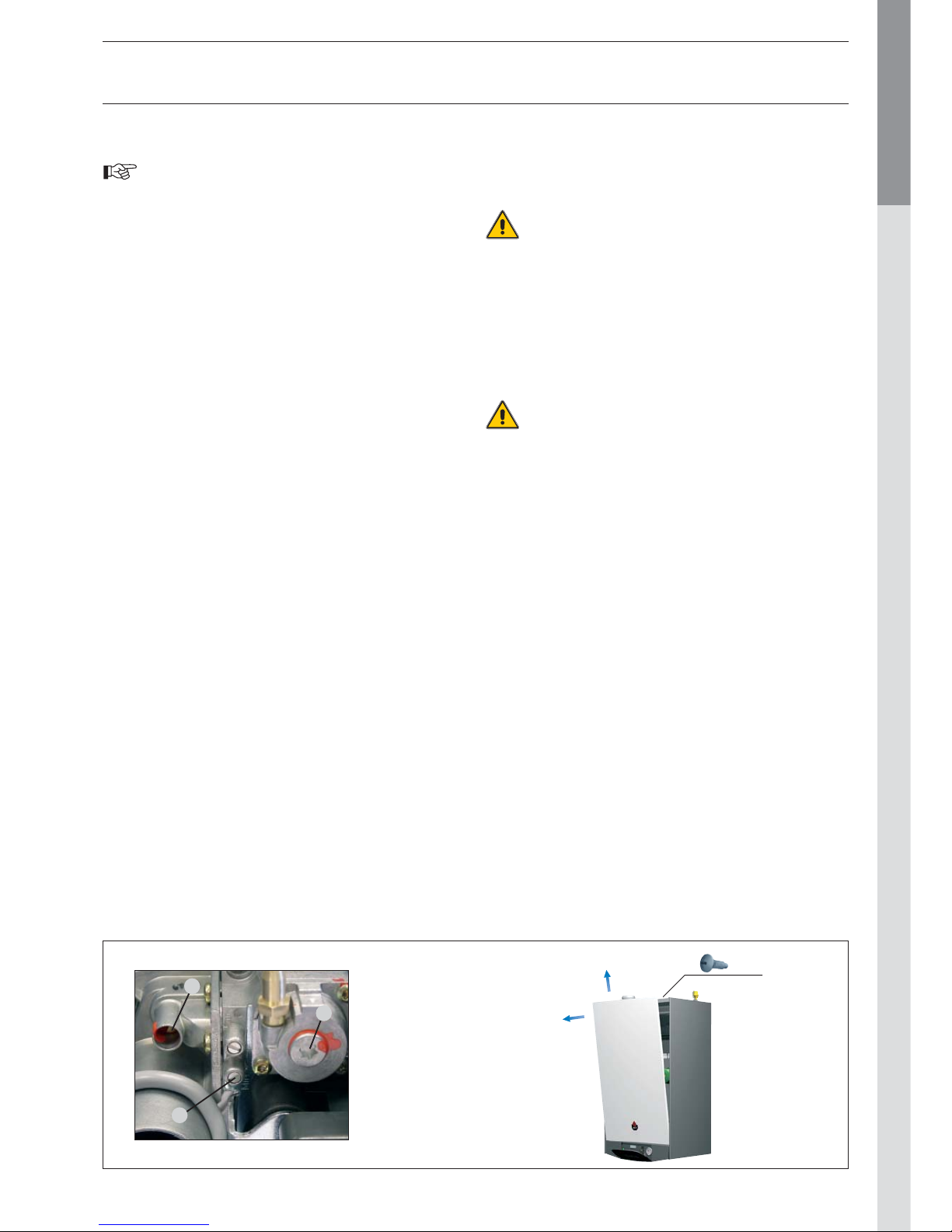
- Set the appliance to High Power mode by simultaneously pressing
the mode and Plus keys.
- Check the dynamic gas pressure at the gas valve (see diagram
below, ref. 1)
. This must be at least 18 mbars.
Wait a few minutes for the appliance to heat up to a minimum
temperature of 60°C. Check the CO2 setting using a measurement instrument. Please see in the Technical Characteristics
for optimum value. To increase the CO
2 value, turn the venturi
screw counterclockwise; turn it clockwise to reduce the value
(see diagram below ref. 2).
Then put the appliance to High Power mode by simultaneously
pressing the mode and Plus keys. Wait a few minutes to stabilise.
Check the CO
2 value. It should be either equal to the full power
value or a maximum of 0.5% less than this value. If you record
a significant deviation,please contact the ACV maintenance
department.
INSPECTION AND MAINTENANCE
ACV recommends that you have your boilers inspected
and cleaned if need be at least once a year.
Plug out the appliance before undertaking any work, even if only
recording measurements and adjusting the settings.
- Check that the siphon is not fouled, fill it, if need be, and check
that there are no leaks.
- Check that the safety valves are operating correctly.
- Drain the whole system and if necessary re-fill the appliance to
pressure of 1.5 bar.
If you have to refill your circuit more than twice a year,
please contact your installer.
- Check the boiler charge in High Power mode. If there is a big
difference between this value and the original setting, the deviation could mean a blockage in the air intake pipes or flue gas
extraction pipes, or that the exchanger has become fouled with
an accumulation of dirt.
- AquaSpeed: Check the domestic hot water flow and the
temperature. These values could indicate a poorly regulated
flow limiter (new setting) or, in areas where the water is very
hard, gradual scale formation in the exchanger. To clean the
AquaSpeed minitank with chemicals, you can connect the
descaling pump directly to the hot and cold water connection.
Follow the manufacturer’s instructions for using the descaler
and the descaling product or contact your ACV distributor for
more information.
Ref.3
The gas valve
offset setting is
a sealed factory
setting.
In principle,
it may not be
modified.
2
1
3
X 2
Page 24
EN • 24
ENGLISHFRANCAISNEDERLANDSESPAÑOLITALIANODEUTSCH
COMMISSIONING AND MAINTENANCE
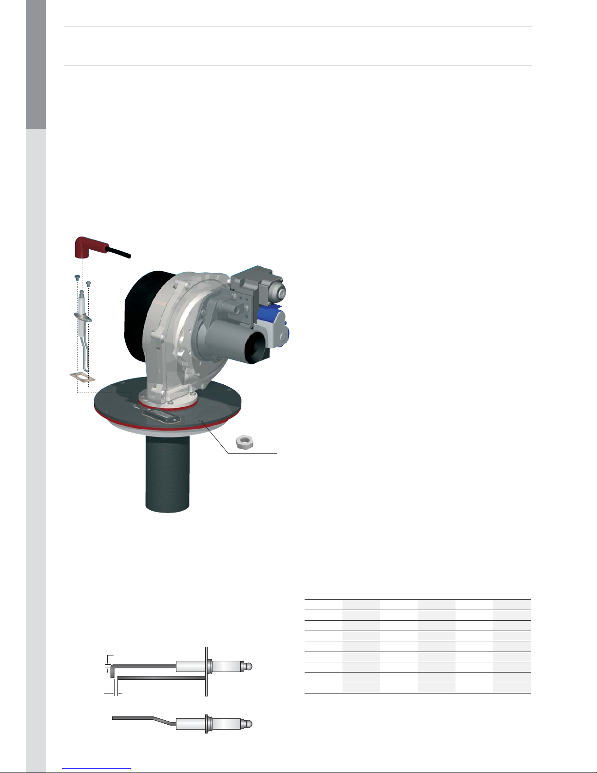
DISASSEMBLING THE BURNER
- Close the inlet gas valve.
- Remove the front panel of the boiler.
- Unplug the fan plugs (24 Volt), the ignition cable, the gas valve
control and the ignition electrode earth.
- The upper jacket panel is removable for an easier access.
- Loosen the 4 burner nuts using a ratchet wrench.
- Unscrew the three-way coupling on the gas pipe.
- In one unit, lift up the burner with the fan and the gas valve to
remove them from the exchanger. Be careful not to damage
the burner insulation in the exchanger.
- Check the condition of the insulation and the seals and replace
them if necessary before re-assembling the burner following
the same procedure but in the reverse order.
DISASSEMBLING THE EXCHANGER
- Drain the water from the central heating system using the
connection under the appliance.
- Allow the appliance to drain completely.
- Dismantle the electrical connections downstream from the
burner, as well as the NTCs.
- Dismantle the exchanger central heating flow pipes and
return pipes. Exercise caution when dismantling the parts as
residual water may escape from the exchanger.
- Dismantle the connection at the siphon and remove the nut
between the siphon and the exchanger.
- Lif t up the exchanger in one piece standing upright. The
exchanger detaches from its hook and is fully released.
- Check the condition of the seals and replace them if necessary
before re-assembling the
AQUASPEED: DISASSEMBLING THE INVERTED
TANK
- Disconnect all the central heating connections as well as all
the hot and cold water pipes connected to the boiler.
- Empty the central heating system using the fill/drain valve
located under the appliance.
- Disconnect the electrical connection for the charging pump
by pulling out the plug.
- Remove the MCBA assembly plate.
- Unscrew the central heating flow pipe using the three-way
coupling located on top of the charging pump.
- Unscrew the mini-tank return pipe.
- Disconnect the hot and cold wat er pipes from the mini-tank.
- Remove the air vent located above the mini-tank, as well as
the nut located below.
- Remove the mini-tank from the lining and tilt it for wards to
remove it completely.
- Check the condition of the seals and replace them if need be
before re-assembling the mini-tank.
CLEANING THE HEAT EXCHANGER
- Remove the burner assembly as described above.
- Remove the burner gasket.
- Clean the combustion chamber using a vacuum cleaner.
- Disconnect the flue pipe from the exchanger.
- Check if the condensates collector is clean, if necessar y,
clean it.
- Check the burner insulation and the burner gasket; replace
the parts if necessary.
- Check the igniter, replace if necessary
- Reassemble the burner and check for leakages.
- Power up the appliance, set the boiler in full power mode and
recheck for leaks.
- Check the gas pressure and the CO2 level as explained in
previous paragraf.
TEMPERATURE SENSOR RESISTANCE TABLES
DISASSEMBLING AND CHECKING THE ELECTRODE
- Remove the ignition cable.
- Remove the two fixing screws.
- Remove the electrode earth but make sure the serrated
washer is fixed between the earth cable and the electrode
when re-assembling.
- Check the condition of the seals and replace them if necessary
before re-assembling the electrode following the same procedure
but in the reverse order.
3
5
T° [°C] R Ω T° [°C] R Ω T° [°C] R Ω
- 20 98200 25 12000 70 2340
- 15 75900 30 9800 75 1940
- 10 58800 35 8050 80 1710
- 5 45900 40 6650 85 1470
0 36100 45 5520 90 1260
5 28600 50 4610 95 1100
10 22800 55 3860 100 950
15 18300 60 3250
20 14700 65 2750
X 4
Page 25
EN • 25
ENGLISHFRANCAISNEDERLANDSESPAÑOLITALIANODEUTSCH
MCBA PARAMETERS FOR THE SPECIALIST
STANDBY MODE
Standby Mode
After you power down the appliance the screen displays Pilot
mode, as shown in the figure above.
This is the standard MCBA mode. The MCBA automatically
returns to this mode after 20 minutes if no keys have been
pressed on the screen. Any parameters that were modified are
then enabled.
The first character shows the current status of the boiler
depending on the condition of both the boiler and the burner. The
last 2 characters indicate the start temperature.
Once the cause of the blockage has been resolved, the burner
starts automatically within 150 seconds at most.
If the burner is blocked for one of the reasons mentioned above,
the screen display alternates between a 9 followed by the
temperature (two last digits) and b with the error code.
Status Boiler function
Standby, no demand for heat
Fan first, fan after
Ignition
Operation of the boiler burner for the heating
Operation of the boiler burner for the
domestic hot water
Air pressure limit or obtaining
the number of start revolutions
The burner goes out when the specified value
is reached.
A demand for heat is present nonetheless.
Pump over-run time after the demand for
central heating
Pump over-run time after the demand for
domestic hot water
Burner blocked:
• : T1 > 95°C
•
: T2 > 95°C
•
: T2 - T1 > 10°C after 90 seconds
•
: dT1/dt > maximum gradient T1
•
: water pressure switch not off
•
: no fan signal
•
: erroneous fan signal
•
: T1 - T2 > max. Δ
•
: NTC3 short-circuit
•
: NTC5 short-circuit
•
: NTC3 interrupt
•
: NTC5 interrupt
•
: T5 > T5 max
•
: wait for the fan to start
Status Boiler function
Internal check — three-way valve
Boiler burner in hot water ready function
Test function: Central heating high power
Test function: Central heating low power
Test function: Boiler with fixed number of
revolutions
Page 26
EN • 26
ENGLISHFRANCAISNEDERLANDSESPAÑOLITALIANODEUTSCH
MCBA PARAMETERS FOR THE SPECIALIST
SETTING THE MCBA PARAMETERS
Parameter Mode
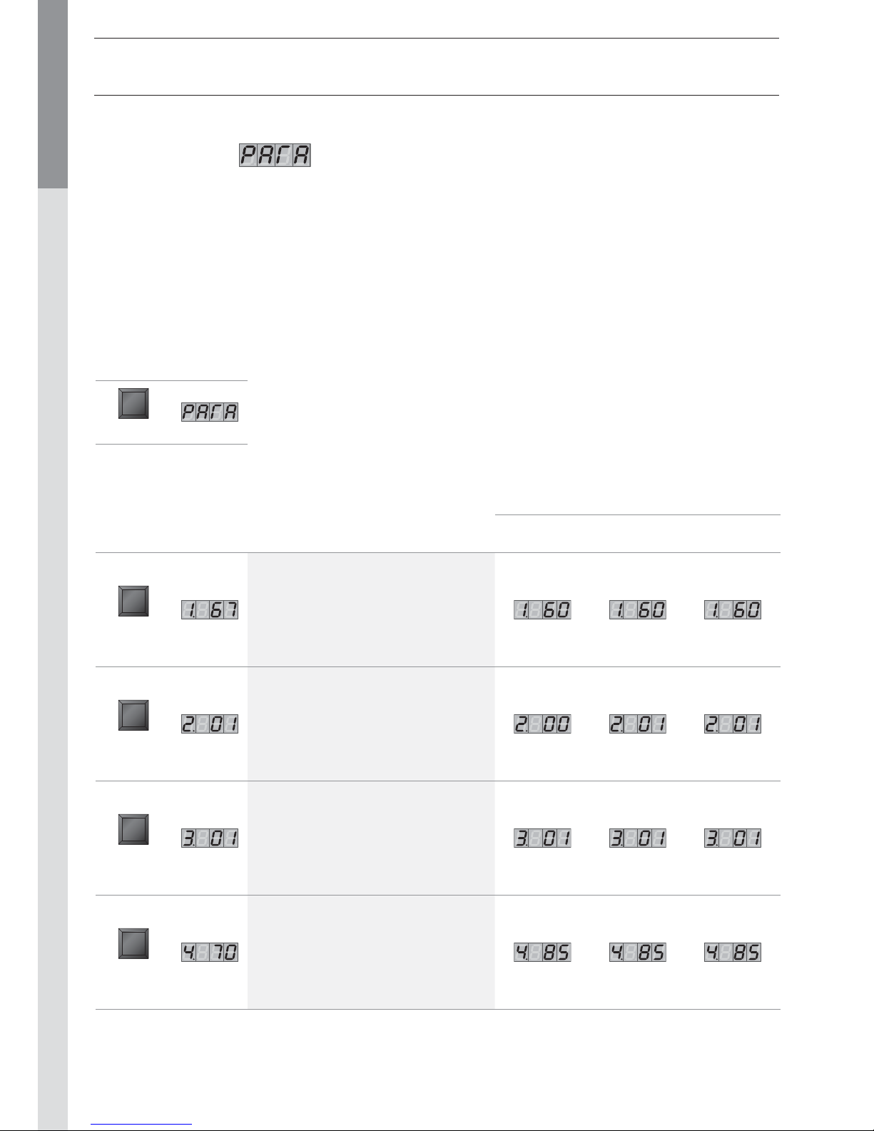
To access Parameter mode when the system is in Pilot mode, press MODE once.
To scroll through the list of parameters, simply press “step”. To modify a parameter value, use the + or - keys.
Then press “Store” to save the value you just changed. The screen flashes once to confirm the data has been saved.
To activate the parameters you changed, press MODE once more (which brings you into Info mode). However, if you do not press a
key, the system returns to Pilot mode after 20 minutes and automatically enables the changes.
Factory setting
Key Screen Description of parameters Solo AquaSpeed Excellence
STEP
Adjusting the hot water temperature
STEP
Production
of hot water
00 = Stop
01 = Start
02 = Stop + pump
continuously on
03 = Start + pump
continuously on
STEP
Turn On/
Turn Off
the heating
00 = Stop
01 = Start
02 = Stop + pump
continuously on
03 = Start + pump
continuously on
STEP
Maximum temperature in
Central Heating mode
Key Screen
MODE
Page 27
EN • 27
ENGLISHFRANCAISNEDERLANDSESPAÑOLITALIANODEUTSCH
MCBA PARAMETERS FOR THE SPECIALIST
ENTERING THE CODE
Code Mode
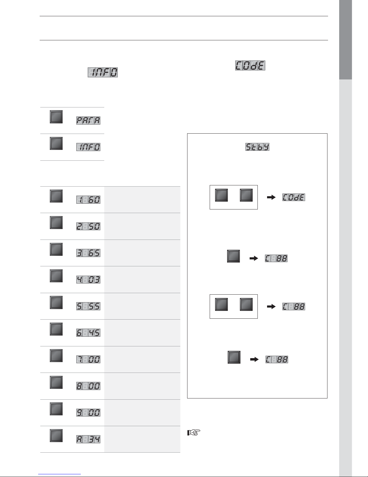
You can access the following parameters by entering the service
code:
• Parameters 5 - 42
• Communication mode
• Fan Speed mode
• ERROR mode
Only ACV authorised installers know the access code.
For further information, please contact our after-sales
department.
To access Code mode, press
MODE and STEP simultaneously
(only from Standby mode!).
MODE STEP
Press STEP once and the system displays C
in position 1, followed by arbitrary
characters in positions 3 and 4.
STEP
Press + or - to change the code..
+ -
Press STORE, the screen flashes briefly
to indicate that the code has been accepted.
STORE
Press MODE until the system
displays the correct mode.
REQUEST FOR INFORMATION
ON THE INSTALLATION
Info Mode
To switch from Standby to Info mode, press Mode twice.
Key Screen
Description of
parameters
STEP
Start temperature T1 in °C
STEP
Return temperature T2 in °C
STEP
Hot water temperature T3 in °C
STEP
Outdoor temperature T4 in °C
STEP
Flue gas temperature
STEP
Start temperature calculated in °C
STEP
Rate of increase in the start
temperature in °C/s
STEP
Rate of increase in the return
temperature in °C/s
STEP
Rate of increase in the hot water
temperature in °C/s
STEP
Start temperature of the 2nd
central heating circuit
Key Screen
MODE
MODE
Press STEP until the system
displays the information you
need. The point located behind
the first position flashes to
indicate that the boiler is in
INFO mode.
or
Page 28
EN • 28
ENGLISHFRANCAISNEDERLANDSESPAÑOLITALIANODEUTSCH
MCBA PARAMETERS FOR THE SPECIALIST
Factory setting
Key Screen Description of parameters Solo AquaSpeed Excellence
STEP
Minimum central heating temperature when
using an outdoor sensor
STEP
Minimum outdoor temperature
[adjust the heating curve]
STEP
Maximum outdoor temperature
[adjust the heating curve]
STEP
Frost protection temperature
STEP
Correction based on the outdoor temperature
STEP
Blockage T
0 = Disabled
STEP
Acceleration time lag
00 = Stop [minute]
STEP
Night set back heating (°C)
STEP
Maximum number of fan
revolutions in CH mode
[rpm x 100]
Prestige 32
natural gas
Prestige 24
natural gas
Prestige 32
propane
Prestige 24
propane
STEP
Maximum number of fan
revolutions in CH mode
[rpm /min.]
Prestige 32
natural gas
Prestige 24
natural gas
Prestige 32
propane
Prestige 24
propane
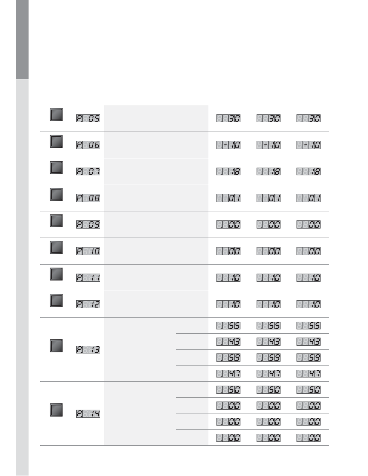
MCBA PARAMETERS WITH CODE RESTRICTED ACCESS
Page 29
FR • 29
ENGLISHFRANCAISNEDERLANDSESPAÑOLITALIANODEUTSCH
MCBA PARAMETERS FOR THE SPECIALIST
Factory setting
Key Screen Description of parameters Solo AquaSpeed Excellence
STEP
Max. number of revs
in domestic hot water mode
[rpm x 100]
Prestige 32
natural gas
Prestige 24
natural gas
Prestige 32
propane
Prestige 24
propane
STEP
Maximum number of fan
revolutions in domestic
hot water mode [rpm]
Prestige 32
natural gas
Prestige 24
natural gas
Prestige 32
propane
Prestige 24
propane
STEP
Minimum number of fan
revolutions [rpm x 100]
Prestige 32
natural gas
Prestige 24
natural gas
Prestige 32
propane
Prestige 24
propane
STEP
Minimum number of fan
revolutions [rpm]
Prestige 32
natural gas
Prestige 24
natural gas
Prestige 32
propane
Prestige 24
propane
STEP
Number of fan revolutions
at ignition [rpm x 100]
Prestige 32
natural gas
Prestige 24
natural gas
Prestige 32
propane
Prestige 24
propane
STEP
CH pump over-run
0 = 10 sec. [step = 1 minute]
STEP
Domestic hot water pump over-run time
[step = 10.2 sec]
Page 30
EN • 30
ENGLISHFRANCAISNEDERLANDSESPAÑOLITALIANODEUTSCH
MCBA PARAMETERS FOR THE SPECIALIST
Factory setting
Key Screen Description of parameters Solo AquaSpeed Excellence
STEP
Central Heating modulation hysteresis enabled
STEP
Central Heating modulation hysteresis disabled
STEP
Domestic hot water modulation hysteresis
enabled
STEP
Domestic hot water modulation hysteresis
disabled
STEP
Detection of domestic hot water hysteresis
enabled
STEP
Detection of domestic hot water hysteresis
disabled
STEP
Central Heating blockage time
[sec. x 10,2]
STEP
Domestic hot water blockage time
[sec. x 10,2]
STEP
Domestic hot water Central Heating
blockage time [sec. x 10,2]
STEP
Re-modulate the difference T1 - T2
STEP
Shell address
[-1 = disabled]
STEP
Temperature increase set point
for the production of hot water
STEP
first position:
2nd heating circuit:
0 = disabled
1= enabled [slave]
2 = enabled [master]
Second position:
the demand for heat comes from:
0 = the room thermostat
1 = the outdoor sensor
Page 31
EN • 31
ENGLISHFRANCAISNEDERLANDSESPAÑOLITALIANODEUTSCH
MCBA PARAMETERS FOR THE SPECIALIST
Factory setting
Key Screen Description of parameters Solo AquaSpeed Excellence
STEP
First position:
Domestic hot water pump [1] or
three-way mixer tap [2]
Second position:
tank with NTC3 probe [2] or
tank with thermostat (3)
STEP
Manual fan number of revolutions
STEP
First position:
Fan control pump level during burning in
Second position:
Fan control pump level during over-run
time
STEP
Hold temperature
STEP
Maximum temperature for the start heating
curve for the 2nd circuit
STEP
Minimum temperature for the start heating
curve for the 2nd circuit
STEP
2nd circuit temperature hysteresis
STEP
First position:
Special pump
[0 = disabled]
Second position:
Minimum disable cycle
[0 = disabled]
Page 32
EN • 32
ENGLISHFRANCAISNEDERLANDSESPAÑOLITALIANODEUTSCH
ERROR MODE [with code]
ERROR mode indicates the most recent error, as well as the
status of the boiler and its readings at the time this error
occurred.
Key Screen
MODE
COMMUNICATION MODE [with code]
When in this mode, the system displays the communication
between the boiler and the control module, the optional interface
kit or the optional programmable room thermostat.
Key Screen
MODE
Key Screen
Description of
parameters
STEP
Code mode
STEP
Status of the boiler at the time
of the error
STEP
Start temperature T1 at the time
of the error
STEP
Return temperature T2 at the time
of the error
STEP
Hot water temperature T3 at
the time of the error
STEP
Outdoor temperature T4 at the
time of the error
Key Screen
Description of
parameters
STEP
No communication
Communication between the
boiler module and the optional
control modules only
Communication between all the
devices connected
Key Screen
Description of
parameters
MODE
Fan speed
STEP
The current fan speed is
5,500 rpm.
FAN MODE [with code]
MCBA PARAMETERS FOR THE SPECIALIST
Page 33
EN • 33
ENGLISHFRANCAISNEDERLANDSESPAÑOLITALIANODEUTSCH
MCBA PARAMETERS FOR THE SPECIALIST
Codes Description of the fault Resolution of the fault
Abnormal flame signal
- Check the wiring (short-circuit in the 24V wiring)
- Check the electrode
- Replace the MCBA (water damage)
No flame signal after five attempts at firing the boiler
- Check the ignition cable
- Check the electrode and the position of the electrode
- Check that there is gas at the burner.
Internal error
If the problem persists after two RESET attempts,
replace the MCBA.
Persistent lock Press “RESET”
Internal error
If the problem persists after two RESET attempts,
replace the MCBA.
EPROM error
If the problem persists after two RESET attempts,
replace the MCBA.
Max input, thermostat open or 24V fuse gone.
- Check the wiring
- Check the 24V fuse on the MCBA.
Internal error
If the problem persists after two RESET attempts,
replace the MCBA.
T1 > 110°C
- Check the NTC wiring and replace if necessary.
If NTC1 is OK, please verify that the water flows trough the
boiler.
T2 > 110°C - Check the NTC wiring and replace if necessary.
T1 gradient too high
- Check that the pump is turning.
- If there is no problem with the pump, drain the system.
No fan signal present
- Check the fan control connection
- Check the fan wiring
If the problem persists after two RESET attempts,
replace the MCBA.
The tacho signal of the blower does’nt go to zero.
- Check that the convection flow through the chimney is not
high enough to rotate the blower.
If not, exchange the blower.
NTC1 short-circuit
- Check the connection of the NTC1 sensor
- Check the wiring of the NTC1 sensor
If the problem persists, replace the NTC1 sensor
NTC2 short-circuit
- Check the connection of the NTC2 sensor
- Check the wiring of the NTC2 sensor
If the problem persists, replace the NTC2 sensor
To unlock the system:
• Press RESET on the screen.
• Contact your installer if the fault happens again.
SAFETY STOP [ERROR mode]
If a fault occurs while the appliance is running, the system locks
and the screen starts to flash. The first character is an E and the
next two characters give the code for this fault, as illustratedin
the table below.
Page 34
EN • 34
ENGLISHFRANCAISNEDERLANDSESPAÑOLITALIANODEUTSCH
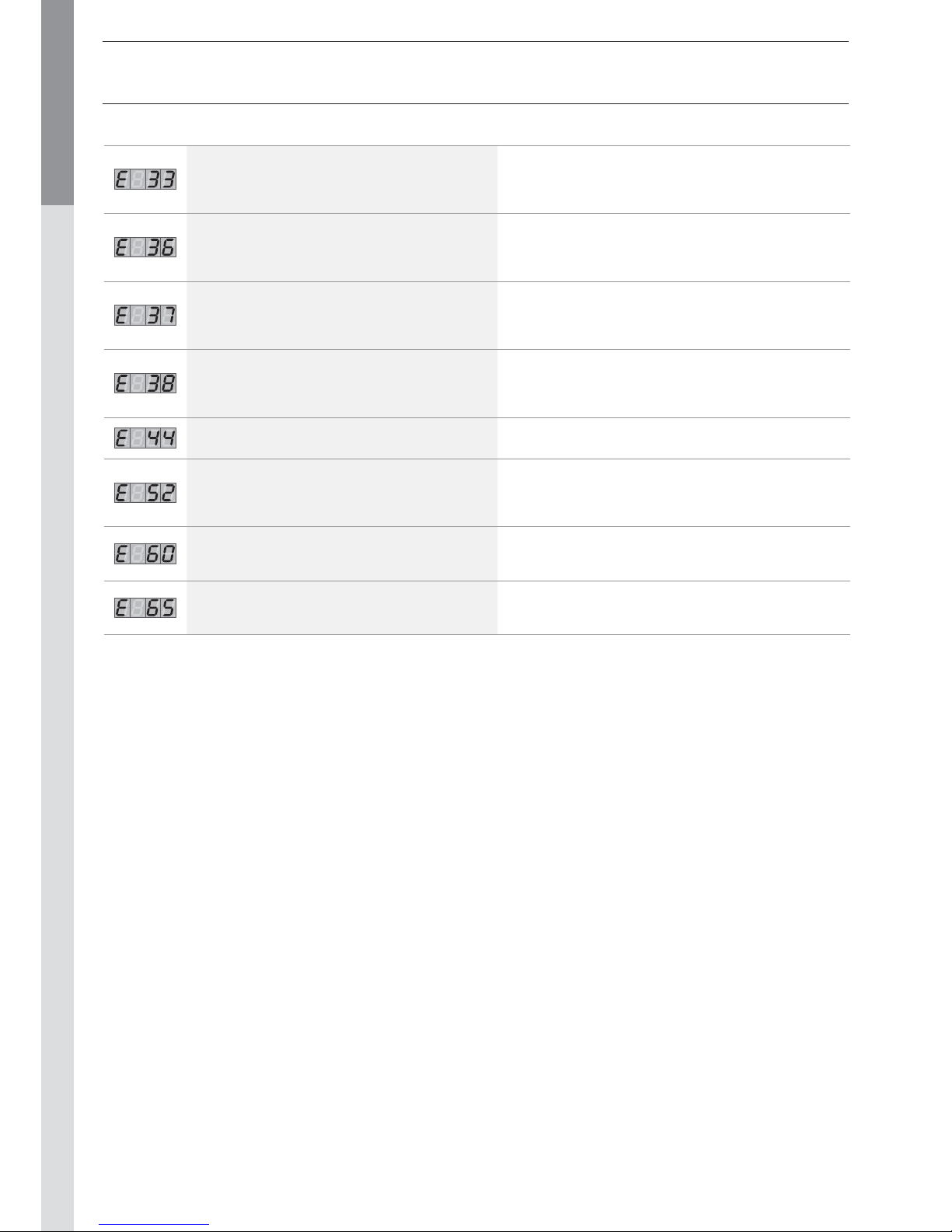
MCBA PARAMETERS FOR THE SPECIALIST
Codes Description of the fault Resolution of the fault
NTC3 short-circuit
- Check the connection of the NTC3 sensor
- Check the wiring of the NTC3 sensor
If the problem persists, replace the NTC3 sensor
NTC1 connection open
- Check the connection of the NTC1 sensor
- Check the wiring of the NTC1 sensor
If the problem persists, replace the NTC1 sensor
NTC2 connection open
- Check the connection of the NTC2 sensor
- Check the wiring of the NTC2 sensor
If the problem persists, replace the NTC2 sensor
NTC3 connection open
- Check the connection of the NTC3 sensor
- Check the wiring of the NTC3 sensor
If the problem persists, replace the NTC3 sensor
Internal error
If the problem persists after two RESET attempts,
replace the MCBA.
Flue gas temperature too high (NTC5)
- Check the connection of the NTC5 sensor
- Check the wiring of the NTC5 sensor
If the problem persists, replace the NTC5 sensor
Error while reading the parameters
Press RESET
If the error persists, replace the MCBA.
Problem with the power supply to the fan
- Check the MCBA power supply voltage.
If it is OK, replace the fan.
Page 35

Page 36

N° EN FR NL ES IT DE
01
Horizontal
oulet
Terminal
horizontal
Muurdoorvoer
Terminal
horizontal
Tereminale
orizzontale
Waagerechte
Wanddurchführung
02
Vertical
outlet
Terminal
vertical
Dakdoorvoer
Terminal
vertical
Terminale
verticale
Senkrechte
Dachdurchführung
03
Flue pipe
L 250 mm
Conduite
L 250 mm
Rookgaspijp
L 250 mm
Tu bo
L 250 mm
Prolunga
L 250 mm
Rohr
L 250 mm
04
Flue pipe
L 500 mm
Conduite
L 500 mm
Rookgaspijp
L 500 mm
Tu bo
L 500 mm
Prolunga
L 500 mm
Rohr
L 500 mm
05
Flue pipe
L 1000 mm
Conduite
L 1000 mm
Rookgaspijp
L 1000 mm
Tu bo
L 1000 mm
Prolunga
L 1000 mm
Rohr
L 1000 mm
06
Adjustable flue pipe
L 500 mm
adjustable
L 235 - 400 mm
Conduite
L 500 mm
réglable
L 325 - 400 mm
Regelbare
rookgaspijp
L 500 mm instelbaar
L 235 - 400 mm
Tubo L 500 mm
regulable
L 325 - 400 mm
Prolunga
L 500 mm
regolabile
L 325 - 400 mm
Verstellbares Rohr
L 500 mm
einstellbar
L 325 - 400 mm
07
Flue bend
45°
Coude 45° Bocht 45° Codo 45° Curva 45°
Bogen
45°
08
Flue bend
90°
Coude 90° Bocht 90° Codo 90° Curva 90°
Bogen
90°
09
Condensate
recovery
Récupérateur
de condensats
Condensopvang
Recuperador
de condensados
Recuperatore
di condensati
Kondensatsammler
10
Measuring
element
Tube de mesure Meetelement Tubo de medida
Elemento
di misura
Messelement
11
Parallel
connection
adapter
Adaptateur de
raccordement
en parallèle
Parallel
aansluitingsadapter
Adaptador de
conexión
paralelo
Adattatore di
collegamento
in parallelo
Paralleler
Verbindungsadapter
12
Adjustable
flashing
Solin réglable
Regelbare
losse pan
Te adaptador
para chimenea
desdodlada
Tegola regolabile Bleidachpfanne
13
Flat roof
flashing
Solin toit plat
Losse pan
plat dak
Cubreaguas
chimenea
Tegola a
tetto piatta
Flachdachflansch
14
Bracket
Ø 125 mm
Attache de
fixation
Ø 125 mm
Bevestiging
Ø 125 mm
Brida fijación
Ø 125 mm
Supporto
di fissazione
Ø 125 mm
Befestigung
Ø 125 mm
Page 37
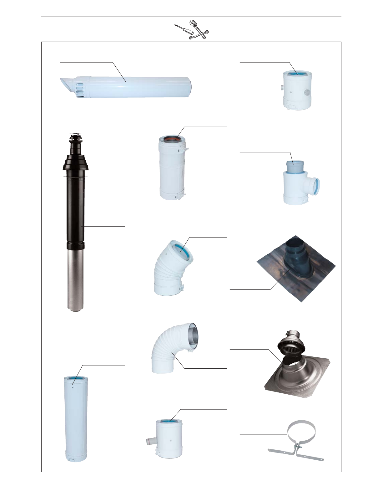
01 : 537D6185
02 : 537D6184
03 : 537D6186
04 : 537D6187
05 : 537D6188
06 : 537D6189
07 : 537D6190
08 : 537D6191
09 : 537D6192
10 : 537D6193
11 : 537D6232
12 : 537D6195
13 : 537D6194
14 : 537D6183
Page 38
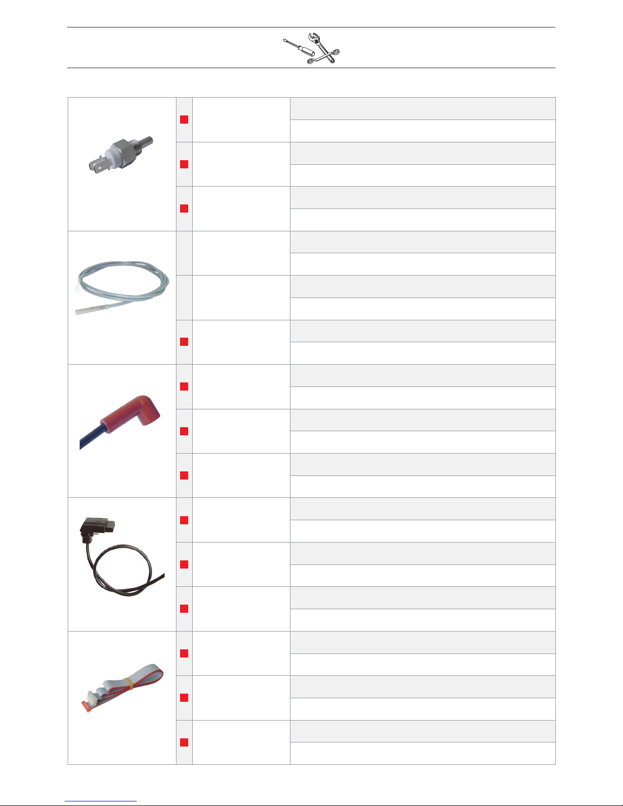
5476G008
Prestige Solo
EN :
NTC sensor [5 x 18 = 12 kΩ]
FR :
Sonde NTC [5 x 18 = 12 kΩ]
Prestige AquaSpeed
NL :
NTC voeler [5 x 18 = 12 kΩ]
ES :
Sonda NTC [5 x 18 = 12 kΩ]
Prestige Excellence
IT :
Sonda NTC [5 x 18 = 12 kΩ]
DE :
NTC-Fühler [5 x 18 = 12 kΩ]
547D3018
Prestige Solo
EN :
DHW NTC sensor - 12 kΩ
FR :
Sonde NTC sanitaire - 12 kΩ
Prestige AquaSpeed
NL :
NTC voeler sanitair - 12 kΩ
ES :
Sonda NTC sanitaria - 12 kΩ
Prestige Excellence
IT :
Sonda NTC sanitaria - 12 kΩ
DE :
NTC- Brauchwasserfühler - 12 kΩ
257F1071
Prestige Solo
EN :
Ionisation and ignition cable
FR :
Câble d’ionisation et d’allumage
Prestige AquaSpeed
NL :
Ontsteek / ionisatie kabel
ES :
Cable de ionización y encendido
Prestige Excellence
IT :
Cavo di accensione e d’ionizzazione
DE :
Ionisations- und Zündungskabel
537D3039
Prestige Solo
EN :
Rectifier [24 Volt]
FR :
Câble rectificateur [24 Volt]
Prestige AquaSpeed
NL :
Gelijkrichter [24 Volt]
ES :
Cable rectificador [24 Volt]
Prestige Excellence
IT :
Cavo rettificatore [24 volt]
DE :
Gleichrichter [24 Volt]
257F1079
Prestige Solo
EN :
Flat cable
FR :
Câble plat
Prestige AquaSpeed
NL :
Kabel display
ES :
Cable plano
Prestige Excellence
IT :
Cavo piatto
DE :
Kabel display
Page 39
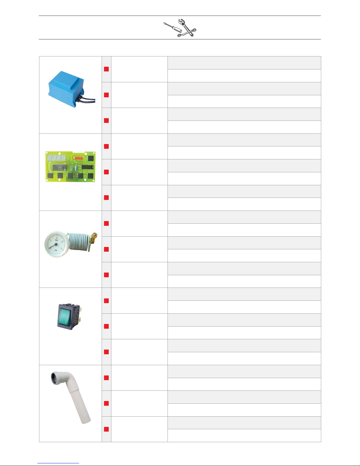
547D3021
Prestige Solo
EN :
Transformer [230 Volt / 24 Volt]
FR :
Transformateur [230 Volt / 24 Volt]
Prestige AquaSpeed
NL :
Transformator [230 Volt / 24 Volt]
ES :
Transformador [230 Volt / 24 Volt]
Prestige Excellence
IT :
Trasformatore [230 Volt / 24 Volt]
DE :
Transformator [230 Volt / 24 Volt]
537D3020
Prestige Solo
EN :
Display board
FR :
Platine display
Prestige AquaSpeed
NL :
Display
ES :
Display
Prestige Excellence
IT :
Scheda display
DE :
Display
54763010
Prestige Solo
EN :
Pressure gauage [0 - 4 bars]
FR :
Manomètre [0 - 4 bars]
Prestige AquaSpeed
NL :
Manometer [0 - 4 bar]
ES :
Manómetro [0 - 4 bares]
Prestige Excellence
IT :
Manometro [0 - 4 bar]
DE :
Manometer [0 - 4 bar]
54766016
Prestige Solo
EN :
ON / OFF switch
FR :
Interrupteur général
Prestige AquaSpeed
NL :
Hoofdschakelaar
ES :
Interruptor general
Prestige Excellence
IT :
Interruttore generale
DE :
An / Aus Schalter
497B0025
Prestige Solo
EN :
Air inlet tube to venturi
FR :
Tube d’entrée d’air venturi
Prestige AquaSpeed
NL :
Inlaatbuis venturi
ES :
Tubo de entrada de aire venturi
Prestige Excellence
IT :
Tubo d’ingresso dell’aria nel venturi
DE :
Eintrittrohr Venturi
Page 40
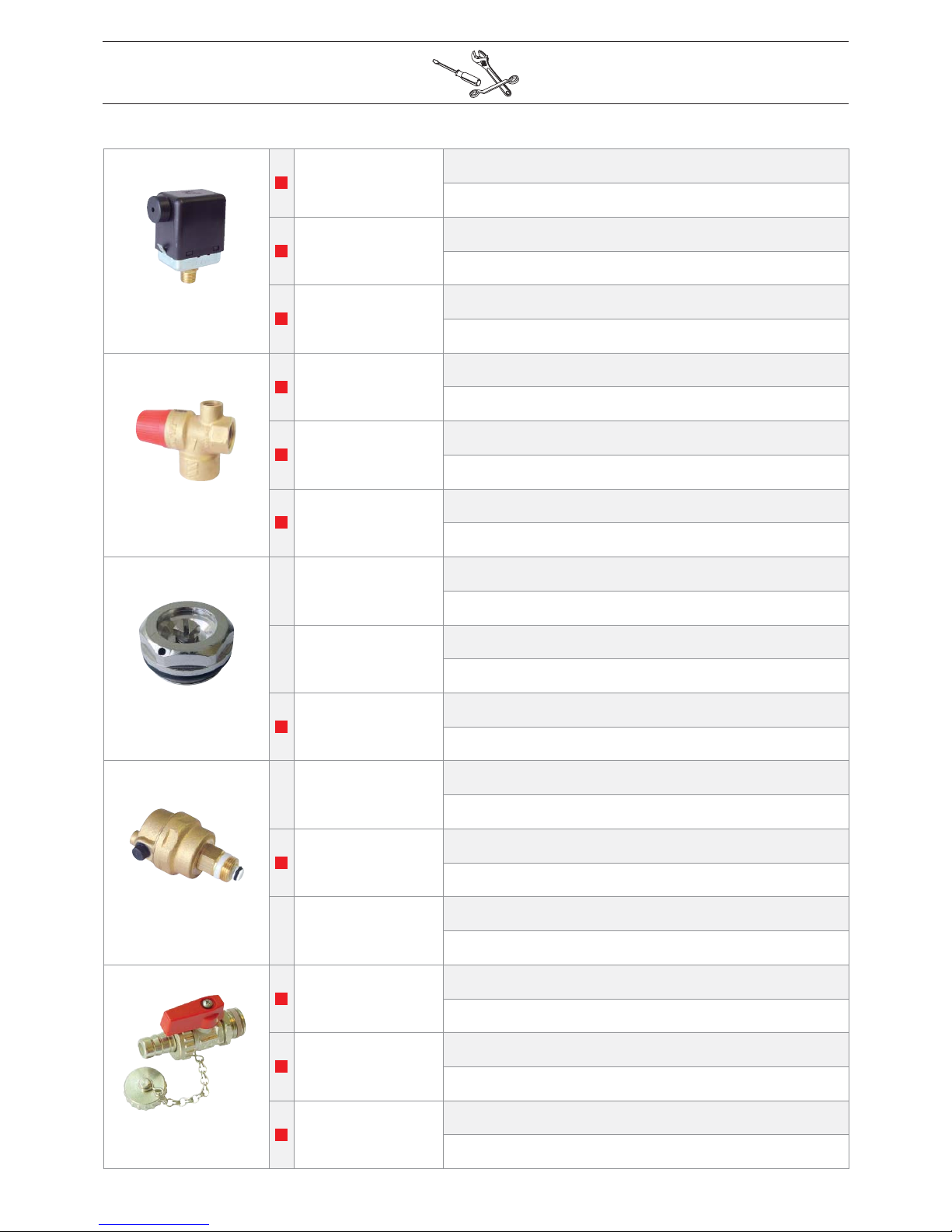
557D3011
Prestige Solo
EN :
Water pressure safety switch
FR :
Pressostat de sécurité manque d’eau
Prestige AquaSpeed
NL :
Waterdruk schakelaar
ES :
Presostato falta de agua
Prestige Excellence
IT :
Pressostato di sicurezza mancanza d’acqua
DE :
Wassermangelsicherung
55426017
Prestige Solo
EN :
Safety valve [3 bars / Ø 1/2” - Ø 3/4”]
FR :
Soupape de sécurité [3 bars / Ø 1/2” - Ø 3/4”]
Prestige AquaSpeed
NL :
Veiligheidsventil [3 bar / Ø 1/2” - Ø 3/4”]
ES :
Válvula de seguridad [3 bares / Ø 1/2” - Ø 3/4”]
Prestige Excellence
IT :
Valvola di sicurezza [3 bar / Ø 1/2” - Ø 3/4”]
DE :
Sicherheitsventil [3 bar / Ø 1/2” - Ø 3/4”]
55445006
Prestige Solo
EN :
Manual air vent [Ø 3/4”]
FR :
Purgeur manuel [Ø 3/4”]
Prestige AquaSpeed
NL :
Manuele ontluchter [Ø 3/4”]
ES :
Purgador manual [Ø 3/4”]
Prestige Excellence
IT :
Valvola di spuro manuele [Ø 3/4”]
DE :
Manueller Entlüfter [Ø 3/4”]
55445007
Prestige Solo
EN :
Automatic air vent
FR :
Purgeur automatique
Prestige AquaSpeed
NL :
Automatische ontluchter
ES :
Valvola di spurgo automático
Prestige Excellence
IT :
Purgeur automatico
DE :
Automatischer Entlüfter
55426001
Prestige Solo
EN :
Drain cock valve [Ø 1/2”]
FR :
Robinet de vidange [Ø 1/2”]
Prestige AquaSpeed
NL :
Leegloopkraan [Ø 1/2”]
ES :
Grifo de vaciado [Ø 1/2”]
Prestige Excellence
IT :
Valvola di scarico [Ø 1/2”]
DE :
Entleerungshahn [Ø 1/2”]
Page 41
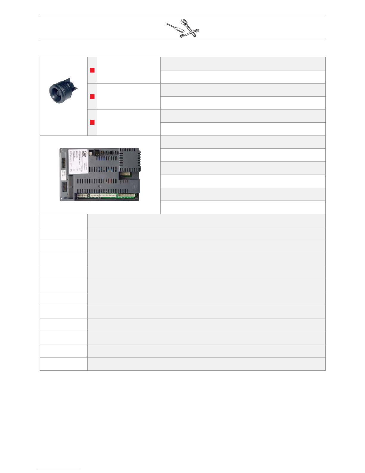
557A6006
Prestige Solo
EN :
Non return valve
FR :
Clapet anti-retour
Prestige AquaSpeed
NL :
Terugslagklep
ES :
Válvula anti-retorno
Prestige Excellence
IT :
Volvola di ritegno
DE :
Rückschlagventil
EN :
MCBA burner control
FR :
Module de contrôle MCBA
NL :
Brander module MCBA
ES :
Módulo de control MCBA
IT :
Centralina MCBA
DE :
MCBA- Brennersteuerung
5476G014
Prestige AquaSpeed 24 kW
5476G015
Prestige Excellence 24 kW
5476G016
Prestige Solo 24 kW
5476G017
Prestige AquaSpeed 24 kW [Propane - Propane - Propaan - Propano - Propano - Propangas]
5476G018
Prestige Excellence 24 kW [Propane - Propane - Propaan - Propano - Propano - Propangas]
5476G019
Prestige Solo 24 kW [Propane - Propane - Propaan - Propano - Propano - Propangas]
5476G020
Prestige AquaSpeed 32 kW
5476G021
Prestige Excellence 32 kW
5476G022
Prestige Solo 32 kW
5476G023
Prestige AquaSpeed 32 kW [Propane - Propane - Propaan - Propano - Propano - Propangas]
5476G024
Prestige Excellence 32 kW [Propane - Propane - Propaan - Propano - Propano - Propangas]
5476G025
Prestige Solo 32 kW [Propane - Propane - Propaan - Propano - Propano - Propangas]
Page 42

N° EN FR NL ES IT DE
A01
Side panel Latérale Zijkanten Lateral Laterale Seitenblech
A02
Front panel Face avant Frontstuk Parte delantero Pannello anteriore Vorderblech
A03
Top cover Couvercle supérieur Bovenkap Tapa superior Coperchio superiore Obere Abdeckung
A04
Rear panel Panneau arrière Achterpaneel Panel trasero Pannello posteriore Hinterblech
A05
Control panel
[ABS]
Tableau
[ABS]
Paneel
[ABS]
Panel
[ABS]
Pannello
[ABS]
ABS-Tafel
A06
Wall mounting Fixation murale Wandbevestiging Fijación mural Fissaggio murale Wandhalterung
A07
Control panel
attachment left
Tableau
prolongement gauche
Paneel verlengstuk
links
Elemento izquierdo
del panel
Elemento sinistro
del pannello
ABS-Tafel
Verlängerung links
A08
Control panel
attachment right
Tableau
prolongement droite
Paneel verlengstuk
rechts
Elemento derecho
del panel
Elemento destro
del pannello
ABS-Tafel
Verlängerung rechts
A09
Back cover
plate display
Protection arrière
du display
Afschermplaat
display achter
Protección
posterior
del display
Protezione
posteriore del
display
Abschirmung hinter
display
A10
Bottom panel
Jaquette
inferieure
Onderpaneel Panel inferior
Pannello
inferiore
Unterblech
A11
Expansion vessel
support
Support vase
d’expansion
Steun expansievat
Apoyo vaso
de expansión
Appoggio vaso
di espansione
Träger
Ausdehnungsgefass
Page 43
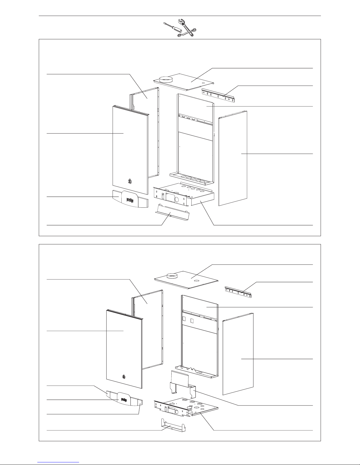
A01 : 21471420
A03 : 21475420
Prestige Excellence
A02 : 21473420
A06 : 21480069
A04 : 21474420
A01 : 21471420
A05 : 54761008
Prestige Solo / AquaSpeed
A07 : 497B6002
A09 : 2147E420
A10 : 21476420
A08 : 497B6003
A11 : 2247F420
A01 : 21471419
A03 : 21475419
A02 : 21473419
A06 : 21480069
A04 : 21474419
A01 : 21471419
A05 : 54761008
A09 : 2147E419
A10 : 21476419
Page 44

N° EN FR NL ES IT DE
B01
Flue gas pipe
Ø 80mm
Tube de fumées
Ø 80mm
Rookgas pijp
Ø 80mm
Tubo de humos
Ø 80mm
Condotto fumi
Ø 80 mm
Abgasrohr
Ø 80mm
B02
Heat
exchanger
Echangeur
de chaleur
Warmtewisselaar
Intercambiador
de calor
Scambiatore
di calore
Wärmetauscher
B03
Exchanger
flow pipe
Tube de dépar t
de l’échangeur
Aanvoerleiding
warmtewisselaar
Tubo de salida del
intercambiador
de calor
Tubo di mandata
da lo scambiatore
Vorlaufrohr
Wärmetauscher
B04
Heating
circulator
1” - L 130 mm
Circulateur
chauffage
1” - L 130 mm
Verwarming
circulator
1” - L 130 mm
Circulador
de calefacción
1” - L 130 mm
Circolatore
riscaldamento
1” - L 130 mm
Heizungspumpe
1” - L 130 mm
B05
Heating circulator
flow pipe
Tube dépar t du
circulateur chauffage
Verktrek
Verwarming
circulator pijp
Tubo de salida
del circulador
de calefacción
Tubo di mandata
da lo circolatore
riscaldamento
Vorlaufrohr
Heizungspumpe
B06
Condenstrap
5/4” - L 300 mm
Siphon 5/4”
L 300 mm
Syfon 5/4”
L 300 mm
Sifón 5/4”
L 300 mm
Sifone 5/4”
L 300 mm
Siphon 5/4”
L 300 mm
B07
Gas pipe Tube gaz Gas pijp Tubo gas Tubo gas Gasrohr
B08
Domestic hot
water Tank
Préparateur
ou mini-préparateur
ECS
Sanitair warm
water boiler
Acumulador
de agua caliente
sanitaria
Bollitore
d’acqua calda
sanitaria
Brauchwasser-
bereiter
B09
DHW pump
connection pipe
Tub e d e
raccordement
circulateur ECS
Aansluiting pijp
sanitair circulator
Tubo de conexión
del circulador
sanitario
Tub o d i
collegamento del
circolatore sanitario
Verbiedingungsrohr
Warm Wasser
Lade pumpe
B10
DHW loading pump
1” - L 130 mm
Circulateur ECS
1” - L 130 mm
Sanitaire
circulator
1” - L 130 mm
Circulador
sanitario
1” - L 130 mm
Circolatore sanitario
1” - L 130 mm
Warm Wasser
Lade pumpe
1” - L 130 mm
B11
DHW circulator
outlet pipe
Tube dépar t
circulateur ECS
Uitgang pijp
sanitair circulator
Tubo de salida
del circulador
sanitario
Tubo di mandata
da lo circolatore
sanitario
Vorlaufrohr
Warm Wasser
Lade pumpe
B12
Heating
return pipe
Tube retour
chauffage
Terugvoer
verwarming
pijp
Tubo retorno
de calefacción
Tubo di ritorno
riscaldamento
Heizungsruchlaufrohr
B13
Domestic
cold water
inlet pipe
Tube d’entrée
eau froide
sanitaire
Koudwateraanvoer
pijp
Tubo de llegada de
agua fría sanitaria
Tubo d’ingresso
acqua fredda
sanitaria
Kalteswasser
Eintritssrohr
B14
Domestic
hot water
outlet pipe
Tube dépar t
ECS
Uitgang sanitair
warm water pijp
Tubo salida
de agua caliente
sanitaria
Tubo di mandata
acqua calda
sanitaria
Warm Wasserrohr
B15
Expansion
vessel
Vase
d’expansion
Expansievat
Vaso de
expansión
Vaso
di espansione
Ausdehnungsgefäß
B16
“T” connection of
DHW Tank
Raccord en T du
préparateur ECS
“T” aansluiting
sanitair warm
water boiler
Conexión en “T”
del acumulador
Collegamento “T”
del bollitore
T-Verbindungs
stuck Speicher
Page 45
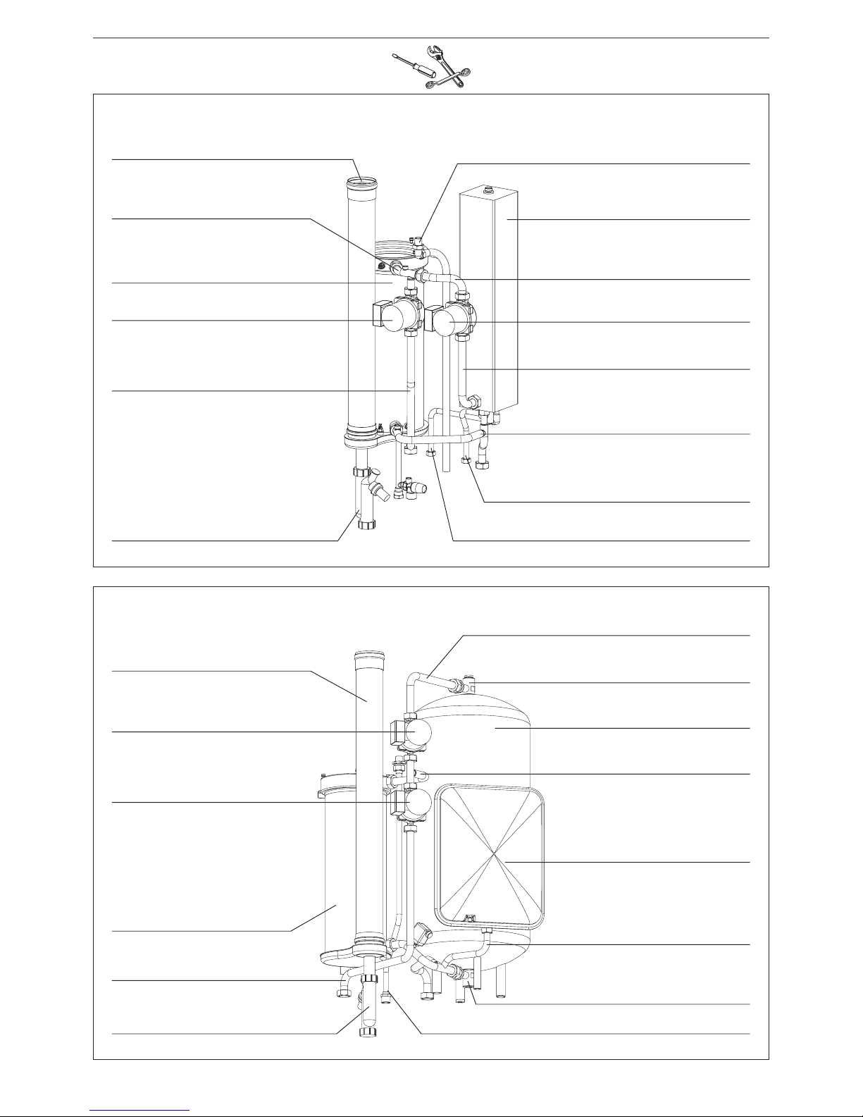
B01 : 497B0031
B11 : 507F4068
Prestige Excellence
B10 : 557A4017
B16 : 507F4066
B08 : 30538481
B15 :557A7008
B04 : 557A4014
Prestige Solo / AquaSpeed
B06 : 557B4002
B07 : 507F4055
B02 : 63962009
B12 : 507F4071
B01 : 497B0031
B07 : 507F4083
B04 : 557A4014
B08 : 507F4035
B10 : 557A4014
B11 : 507F4089
B05 : 507F4087
B06 : 557B4002
B14 : 507F4054
B05 : 507F4070
B03 : 507F4069
B02 : 63962009
B09 : 507F4088
B03 : 507F4086
B13 : 507F4053
B12 : 507F4052
B16 : 507F4066
Page 46
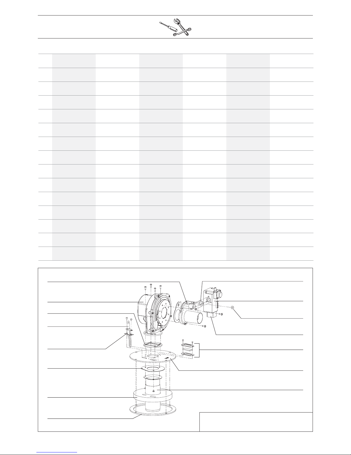
Prestige Solo / AquaSpeed / Excellence
(*)
Burner propane - Brûleur propane - Brander propaan
Quemador propano - Bruciatore propano - Propangasbrenner
C01 : 537D4034
C15 : 557D6039
C02 : 537D3041
C03 : 557A0054
C05 : 557A0012
C06 : 557A0048
C08 : 557A0058
C10 : 507F4095
C14 : 537D4033
C12 : 53402088
C09 : 537DZ025 - (*) 537DZ026
C13 :
(*) 537D4020
C07 : 51700061
C04 : 557DZ023
C11 : 507F4096
N° EN FR NL ES IT DE
C01
Venturi + seal Venturi + joint Venturi + dichting Venturi + junta
Venturi
+ Guarnizione
Venturi + dichtung
C02
Fan Ventilateur Ventilator Ventilador Ventilatore Gebläse
C03
Silicone seal
fan
Joint silicone
ventilateur
Siliconedichting
ventilator
Junta de silicona
ventilador
Guarnizione silicone
del ventilatore
Silikondichtung
Gebläse
C04
Ingnition
electrode
Electrode
d’allumage
Ontstekingselectrode
Electrodo
de encendido
Elettrodo
di accensione
Zündelectrode
C05
Electrode seal Joint électrode Dichting electrode Junta de electrodo
Guarnizione
elettrodo
Dichtung
Elektrode
C06
Burner rod seal
Joint rampe
brûleur
Dichting
branderstaaf
Junta de rampa
quemador
Guarnizione rampa
bruciatore
Dichtung
Brennerlanze
C07
Burner flange
insulation
Isolation plaque
brûleur
Dichting
branderflens
Aislamiento
placa quemador
Isolamento piastra
bruciatore
Isolierung
Brennerflansch
C08
Burner seal
Ø 210 mm
Joint brûleur
Ø 210 mm
Branderdichting
Ø 210 mm
Junta de quemador
Ø 210 mm
Guarnizione
bruciatore Ø 210
Brennerdichtung
Ø 210 mm
C09
Burner rod Rampe brûleur Branderstaaf Rampa quemador Rampa bruciatore Brennerlanze
C10
Burner flange Plaque brûleur Branderflens Placa quemador Piastra bruciatore Brennerflansch
C11
Flame inspection
window
Regard
de flamme
Vlamcontrole Tapa de llama Spioncino fiamma
Schauloch
Flamme
C12
Gas valve
flange Ø 1/2”
Bride vanne
gaz Ø 1/2”
Gasklepflens
Ø 1/2”
Brida de válvula
de gas Ø 1/2”
Piastra valvola
gas Ø 1/2”
Flansh Gasventil
Ø 1/2”
C13
Orifice
Ø 52 mm
Opercule
Ø 52 mm
Diafragma
Ø 52 mm
Diafragma
Ø 52 mm
Diaframma
Ø 52 mm
Diafragma
Ø 52 mm
C14
Gas valve Vanne gaz Gasklep Válvula de gas Valvola gas Gasventil
C15
Venturi O-ring O-ring venturi O-ring venturi Anillo venturi Anello venturi O-Ring venturi
 Loading...