

Page 1

COMPONENTS:
Model APS-520
Installation Manual
Two Way Remote Alarm System
With Start Inhibit and Dual Stage Shock Sensor
1 Control Module
1 Four Button RF Transmitter
1 Four Button LCD Transmitter
2 Way Antenna/Receiver
1 1” X 1.75” Foam Pad
14 Pin Accessory Harness
1 Hood Pin Switch
1/4” Female Spade Connector
FEA TURES:
Four Channel Receiver (Capable Of Accepting Up T o 4 Transmitters)
Code Hopping T echnology
Selectable Manual Override Mode
Remote Panic in all modes
Protected V alet
User Programmable Manual Override Code
7 Function LED (Light Emitting Diode) - Arm / Disarm / Zone 1, 2, 3 / Valet / Arming
Intrusion Alert with Memory
Audible Arm / Disarm / Defective Zone / T amper Confirmation
Instant Siren Activation
Starter Disable
Additional Engine Immobilizer Output (optional relay required)
True Last Door Arming (hardwire only)
Defective Zone By-Pass
Active or Passive Arming Select able
Programmable Auto Lock On / Of f
Programmable Auto Unlock On / Of f
Programmable Door Lock Pulse Duration
Programmable Active or Passive Door Locks
User Programmable Permanent Chirp Delete
On Command RF Chirp Delete from Transmitter
6 T one Multi T one Siren
RF Inhibit with ignition on
Parking Light Flasher
Plug In Dual Stage Shock Sensor
Illuminator Entry Output (optional relay required)
FCC NOTICE
This device complies with part 15 of the FCC rules. Operation of this device is subject to the
following conditions:
(1) This device may not cause harmful interference, and
(2) This device must accept any interference received, including interference that may cause
undesired operation.
Caution: Changes or modifications not expressly approved by the party responsible for
compliance voids the users authority to operate this device.
2 Pin Door Lock/Unlock Harness
St arter Inhibit Relay & Harness
2 Pin LED Assy
2 Pin Push-Button V alet/Program Switch
4 Pin Antenna Receivers Harness
Installation/Owners Guide
4 Phillips Head Black Drill Point Sheet
Metal Screw #8 X 1/2"
2 St age Shock Sensor w/Harness
1
128-8147
1 of 8
Page 2

INST ALLATION OF THE MAJOR COMPONENTS:
CONTROL MODULE:
Select a mounting location inside the passenger compartment (up behind the dashboard). The
mounting location selected must be within 24" of the ignition switch wiring harness to allow
connection of the 6 pin main wiring harness.
Be certain that the chosen location will not interfere with proper operation of the vehicle. Avoid
mounting the module to or routing the wiring around the steering shaft/column, as the module or
wiring may wrap around or block the steering wheel preventing proper control of the vehicle.
Secure the module in the chosen location using cable ties or screws as necessary.
Do Not Mount The Module In The Engine Compartment, as it is not waterproof.
DASH MOUNTED LED:
The small LED included in the kit will serve as a visual indicator of the alarm's status and
provide a visual deterrent to a potential thief. The LED also provides important feed back information during the transmitter and feature program modes. The LED should be installed in the
dash in an area highly visible so that it may be seen from the driver's seat as well as from outside
the vehicle. Inspect behind the chosen location to insure that the drill will not penetrate any
existing factory wiring or fluid lines. Carefully drill a 1/4" hole in the desired location and pass the
connector end of the LED through the hole and toward the control module. Press the LED firmly
into place until it is fully seated in the mounting hole.
THE RECEIVER/ANTENNA ASSEMBLY :
The Super-regenerative Receiver Antenna Assembly provided with this unit allows routing from
below the dash board for maximum operating range. Choose a location above the belt line
(dashboard) of the vehicle for best reception. Special considerations must be made for windshield glass as some newer vehicles utilize a metallic shielded window glass that will inhibit or
restrict RF reception. In these vehicles, route the antenna toward a rear window location for best
reception. Secure the antenna with double stick tape provided. After securing the antenna with
tape, we advise also securing a section of the antenna cable to a fixed support. This will prevent
the antenna from dropping down in case the double stick tape is exposed to extreme heat which
may loosen it's gummed surface. Route the connector toward the control module using caution
not to pinch the cable as this will cause poor or no RF reception to the control module.
VALET/PROGRAM/MANUAL OVERRIDE SWITCH :
Select a mounting location that is easily accessible to the operator of the vehicle. It is not
necessary to conceal the switch. However, concealment is recommended as it offers a higher
level of security . The switch can be mounted to the lower dash p anel in the driver's area. Inspect
behind the chosen location to insure that adequate clearance is allowed for the body of the
switch, and also that the drill will not penetrate any existing factory wiring or fluid lines. Drill a 9/
32" hole in the desired location and mount the switch by passing it through the panel from the
underside. Secure the switch using the nut, star washer. Route the switch's connector toward
the control module.
NOTE: During the program sequence, there are times when this switch and the ignition switch
SIREN:
Select a location in the engine compartment that is not accessible from below the vehicle. The
selected location must be clear of hot or moving parts within the engine compartment The siren
must be pointed downward to prevent water retention and the flared end must be pointed away
from and out of the engine compartment for maximum sound distribution. Before securing the
siren, check behind your chosen location to assure that the mounting screws will not penetrate
any factory wiring or fluid lines. Secure the siren mounting bracket using #8 self taping screws or
by first using the mounting bracket as a template, scribe or mark the mounting holes. Drill the
marked holes using a 1/8" drill bit, then mount the siren using #8 sheet metal screws.
HOOD PIN SWITCH:
The pin switch included in this package are intended for protecting the hood area of the vehicle.
In all cases, the switch must be mounted to a grounded metal surface. When the pin switch is
activated, (hood/trunk open), it will supply a ground to the input wire activating the alarm. In
addition, the hood switch is required for the safety shut down of the remote start unit. If the
vehicle is being worked on, this hood switch prevents the remote start activation even if the RF
command to start is issued. This switch must be installed in all applications. Failure to do so
may result in personal injury or property damage.
Mount the switch in the hood locations away from water drain paths. If necessary, the included
bracket may be used to move the switch away from rain gutters or allow mounting to the firewall
will be used simultaneously. We recommend that the pushbutton switch be mounted
on the left side of the ignition switch to facilitate this operation.
2
128-8147
2 of 8
Page 3

behind the hood seal. In both cases the switch must be set up to allow the hood to depress the
switch at least 1/4 inch when the hood is closed and fully extended when the hood is opened.
For direct mounting, a 1/4 inch hole must be drilled. Carefully check behind the chosen location
to insure the drill will not penetrate any existing factory wiring or fluid lines.
Drill a 1/4" hole in the desired location and thread the pin switch into it using a 7/16" nut driver
or deep well socket. If using the mounting bracket, first secure the bracket to the desired
location and secure the pin switch in the pre-threaded mounting bracket hole.
STARTER INHIBIT RELA Y :
Select a mounting location within 6" of the ignition switch's low current start solenoid wire.
Secure the relay to an existing harness in the chosen location using a cable tie around the
relay's wiring harness.
CAUTION! Do not wire tie the metal bracket to an existing wiring harness as vibration may
SHOCK SENSOR:
Select a centrally located, solid mounting surface for the shock sensor that will allow consistent operation from all areas of the vehicle. The selected location must be within 24" of the
control module to allow routing and connecting of the 4 pin harness. Secure the shock sensor
to the chosen location using two #8 self tapping sheet metal screws. The sensor can also be
secured to an existing dash brace using cable tie straps. Whichever mounting method is used
be sure to allow access to the sensitivity adjustment potentiometer for use later in the installation.
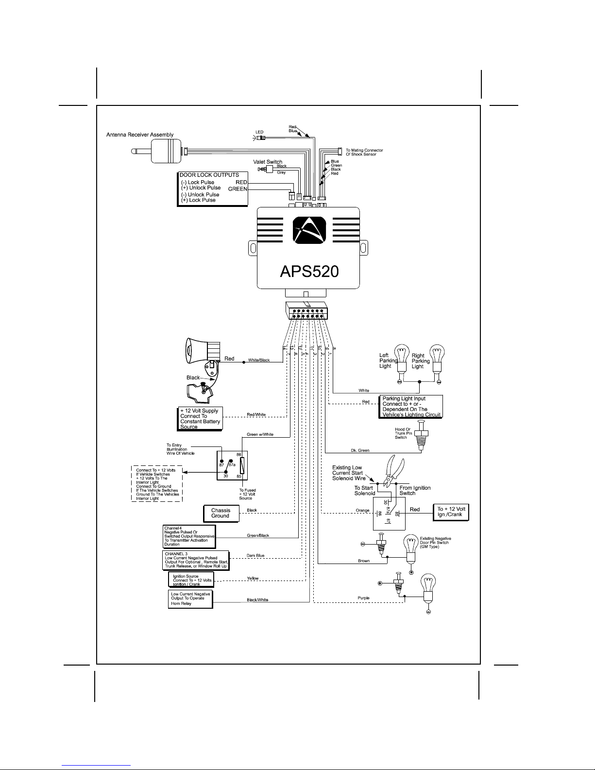
14 Pin Main Harness
Red/White (5Amp) & Red Fused (15Amp) Wires : + 12 VDC CONSTANT BA TTERY SOURCE
This wire controls the sensitivity of the voltage sensing circuit, which detects the turning on of an
interior light when a door is opened. It will also detect the switching on of parking or headlamps,
and in many cases will trigger the alarm when a thermostatically controlled electronic radiator
cooling fan switches on.
When installing this system into vehicles with electronic “ after fans “, it is recommended you
disable the voltage sense circuit.
In voltage sensing applications, the closer to the battery that the red wire is connected, the less
sensitive the voltage sense circuitry will be. Moving this connection point to the fuse panel will
increase the sensitivity, and connecting to the courtesy lamp fuse in the vehicle will provide
maximum sensitivity of the voltage sense circuit. Be certain to set selectable feature # 7 to 1
chirp, Voltage Sense On.
When hardwiring the control module to pin switches at all entry points, the voltage sense circuit
must be disabled.
NOTE: If the vehicle's parking lights are ground switched, connect this wire to chassis ground.
cause chaffing and shorting damaging the factory wiring. If an existing harness is
not available then secure the relay's metal mounting tab to an under dash metal
brace with a #8 self tapping sheet metal screw. Wire the relay as per the diagram
found later in this manual.
Yellow W ire: + 12 VDC IGNITION SOURCE
Connect this wire to a source that is live when the key is in the on and crank positions. Be
sure that this source is off when the key is in the off position.
White Wire: Positive Parking Light Flasher Output
This wire is the normally open contact of the on board parking light flasher relay. Connect this
wire to the vehicle parking light + 12 Volt feed wire.
Orange: Ground While Armed Output
This wire provides a 300 mA ground output when the alarm circuit is armed to control the
starter inhibit relay. Connect the Orange wire to terminal #86 (orange wire) of the relay
provided. Connect terminal #85 (red wire) of the relay to an ignition wire in the vehicle that is
+12 volts when the ignition switch is turned to the on and start positions and off when the key
is off. Locate and cut the low current start solenoid wire found at the vehicles ignition switch
harness. This wire will have + 12 volts when the ignition key is moved to the start (crank)
position and will have 0 volts in all other key positions. Connect one side of the cut wire to
terminal #87a ( Black wire) of the relay. Connect the other side of the cut wire to terminal #30
(White/Black wire) of the relay.
White w/ Black Trace Wire: (+) Siren Output
This is the positive siren feed wire. Route this wire through a grommet in the firewall to the
siren location. Connect the White w/ Black Trace wire to the Red wire of the Siren. Secure the
Black wire of the Siren to a known chassis ground or solid clean metal surface.
Brown Wire: Negative Door Trigger
If the vehicle's door courtesy light switches ground when the door is opened, (Most GMs and
Imports), you must connect this wire to the negative output from one of the vehicle's door pin
3
128-8147
3 of 8
Page 4

switches. In most cases the Brown wire will need to be connected to only one door switch no
matter how many doors the vehicle has as most door lighting circuits are wired in parallel. This
wire will be shunted when remote starting the vehicle and will remain shunted, if active, while
running under command of the remote start. If this wire is active when the system is armed, the
siren will emit three chirps. When the zone clears, the siren will emit 1 chirp to confirm full arming.
NOTE: For vehicles with interior delay lighting see programming under title "Completing The
Purple Wire: (+) Door Trigger Input
If the vehicle's door courtesy light switches + 12 volts when the door is opened, (Some Fords and
some Imports), you must connect this wire to the positive output from one of the vehicle's door pin
switches. In most cases, the Purple wire will need to be connected to only one door switch no
matter how many doors the vehicle has as most door lighting circuits are wired in parallel. This
wire will be shunted when remote starting the vehicle and will remain shunted, if active, while
running under command of the remote start. If this wire is active when the system is armed, the
siren will emit three chirps. When the zone clears, the siren will emit 1 chirp to confirm full arming.
See below for wiring details.
Note for vehicles with interior delay lighting see programming under title "Completing The Installation".
Dark Green Wire: (-) Instant Trigger Input
This is the instant on ground trigger input wire. This wire must be connected to the hood and trunk
pin switches previously installed.
NOTE: This wire will be shunted when remote control channel 3 is accessed, (trunk release).
Black Wire: Chassis Ground Source
Connect the Black wire to a known vehicle ground source or to a solid clean metal part of the
chassis. Be certain to remove any paint or grease and secure this wire with a self tapping screw
and ring terminal.
Dark Blue Wire: Delayed 250 mA Pulsed Channel 3 Output
The Dark Blue wire supplies a 250 mA ground pulsed output whenever channel three of the
receiver is accessed. Pressing the pre-programmed transmitter button for three seconds will
access channel two. This is a low current output and must be connected to a relay to supply
power to the trunk release or the circuit you wish to control. Connect the Dark Blue wire to
terminal # 86 of a VF45F11 P&B relay or equivalent. Connect terminal # 85 of the relay to a
fused + 12 volt source. Connect the common, normally open, and normally closed contacts of
the relay to perform the selected function of channel 3. See below for relay wiring detail.
Green w/ Black Trace Wire: 250 mA Latched Channel 4 Output
The Green w/ Black Trace wire supplies a 300 mA switched output whenever channel four of the
receiver is accessed. Pressing the pre-programmed transmitter button(s) will access channel
four and will remain active, for up to 20 seconds, as long as the transmitter button(s) is held. This
is a low current output and must be connected to a relay to supply power to the device you intend
to control. Connect Green w/ Black Trace wire to terminal #86 of a VF45F11 P&B relay or equivalent. Connect terminal #85 of the relay to a fused + 12 volt source. Connect the common, normally
open, and normally closed contacts of the relay to perform the selected function of the channel 4
output.
Black w/ White Trace Wire : 250 mA Horn Output
The black w/ white trace wire is provided to beep the vehicle’s horn. This is a transistorized
low current output, and should only be connected to the low current ground output from the
vehicle’s horn switch. If the vehicle uses a + 12 VDC horn switch, then connect the black w/
white trace wire to terminal 86 of the AS 9256 relay ( or an equivalent 30 Amp automotive relay
),and connect relay terminal 85 to a fused + 12 VDC battery source. Connect relay terminal 87
to the vehicle’s horn switch output, and connect relay terminal 30 to a fused + 12 VDC battery
source.
Green w/ White trace Wire: Entry Illumination Ground Output
This wire provides a 30 second ground output (250 mA Max.) whenever the remote is used to
disarm the alarm or to unlock the doors and provides a continuous pulsed output whenever
the alarm is triggered. This wire should be connected to an external relay and wired to the
vehicles interior entry lighting whenever the optional Interior Illumination circuit is desired.
4 Pin Shock Sensor Connector
Red, Black Green & Blue wires of the shock sensor harness provide +12 Volts, Ground, Full
Trigger, and Pre-Detect inputs to and from the sensor. Route these wires from the previously
installed sensor and connect to the mating connector on the control module.
Installation".
This wire will remain shunted all the while there is ground present and for 5 seconds
after the ground is removed. This allows the operator to open the trunk via the remote
transmitter without having to first disarm the alarm system.
4
128-8147
4 of 8
Page 5
2 Pin LED Harness, Connector
Route the twin lead Red and Blue wires from the LED to the remote start control unit and plug the
two pin connector into the mating white mini connector on the control module. These wires
control the anode and cathode of the dash mounted LED.
4 Pin Antenna/Transceiver , Connector
Route the 4 pin connector from the previously installed antenna receiver assemble to the mating
connector on the control module. This connector supplies 5 volts, ground and RF data from the
antenna receiver to the remote start module. Be certain this connector is firmly seated making
good contact to the control unit.
2 Pin Valet/Program/Override Pushbutton Switch, Connector
The Black & Black/Gray twin lead wires loaded in the two pin blue connector are the ground
supply and program/valet/override input of the Remote Start unit. Route the two wires from the
previously installed Push-Button switch to the mating connector on the control module.
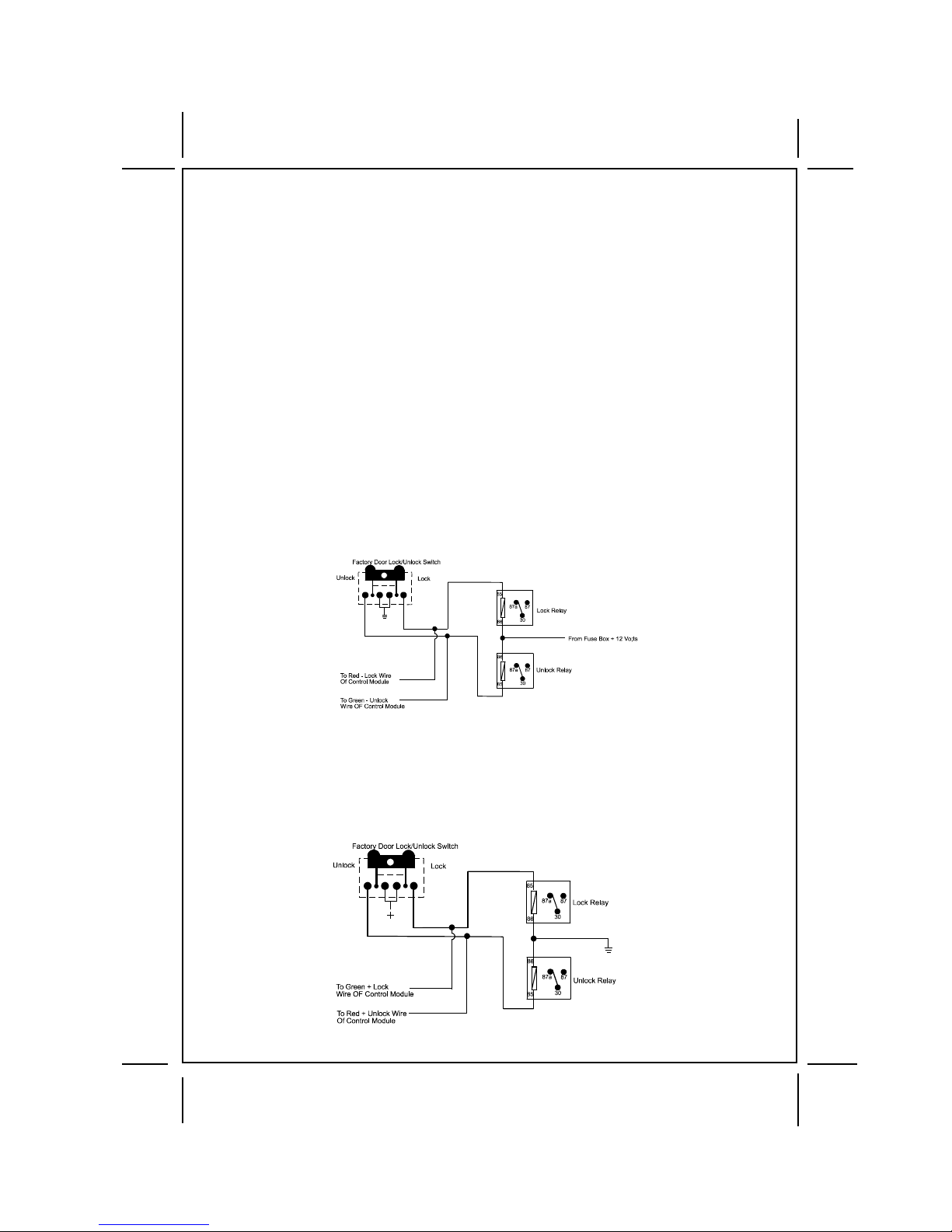
Wiring The 2 Pin Door Lock/Unlock Harness Connector
The Red & Green Door Lock/Unlock output wires provide a pulsed ground output to control the
vehicle door lock / unlock circuits. The output of these wires has a maximum switching capability
of 250 mA. Many vehicles today have factory door lock relays which can be connected directly to
these outputs, however always confirm that the factory relays in your particular vehicle do not
exceed the rated 250 mA output of the units door lock/unlock circuit. Plug the 2 pin connector of the
door lock/unlock harness into the mating connector shell of the control module. Determine the
door lock circuit of the vehicle you are working on and wire according to the diagrams shown.
3 Wire Ground Switched Door Lock Circuits:
In this application, the Red wire of the 2 pin harness provides a ground pulse during the arming
sequence, or pulsed ground lock output. Connect the Red wire to the low current ground signal
wire from the factory door lock switch to the factory door lock relay.
The Green wire of the 2 pin harness provides a ground pulse during the disarming sequence, or
pulsed ground unlock output. Connect the Green wire to the low current ground signal wire from
the factory door unlock switch to the factory door unlock relay.
3 Wire Positive Switched Door Locks:
In this application, the Red wire of the door lock harness provides a + 12 volt pulse during the
disarming sequence, or pulsed 12 volt unlock output. Connect the Red wire to the low current 12
volt signal wire from the factory door unlock switch to the factory door unlock relay.
The Green wire of the door lock harness provides a + 12 volt pulse during the arming sequence,
or pulsed 12 volt lock output. Connect the Green wire to the low current 12 volt signal wire from
the factory door lock switch to the factory door lock relay. See Below For Wiring Detail.
5
128-8147
5 of 8
Page 6
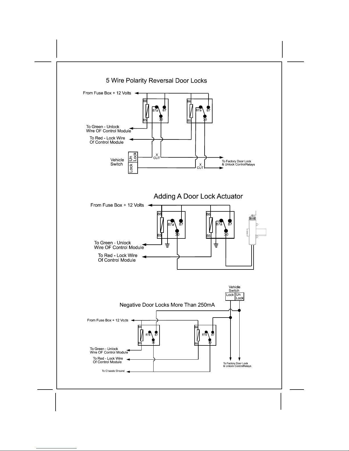
OTHER DOOR LOCKING CIRCUITS ARE SHOWN IN THE FOLLOWING DIAGRAMS:
6
128-8147
6 of 8
Page 7

Setting Up The System Programming Features:
Bank 1 Transmitter Channels:
1. Start with the system disarmed; turn the ignition switch to the on position; then press
and release the pushbutton valet/program switch 3 times.
Siren Chirps once and or Lights flash one time indicating the transmitter program mode
successfully entered. (See Owners Manual for transmitter programming.)
2. Turn the ignition switch off then on to access Bank 2 Keyless/Alarm feature selections.
1 short/1 long chirp when the key transitions off, followed by 1 short/1 long chirp when
the key is turned on indicates that you are in feature selection of bank 2.
3. Press the pushbutton switch 1 time to access the first selection as shown below. Use
the lock button of the transmitter to change the feature selection or press the push-
button to advance to the next selectable feature.
Bank 2
Feature 1 Chirp/Flash 2 Chirp/Flash 3 Chirp/Flash 4 Chirp/Flash 5 Chirp/Flash 6 Chirps/Flash Default
1st Door L/UL 1 Sec. 3.5 Sec. 1 S.L, Dbl.U/L Dbl L, 1 S. UL Dbl L, Dbl UL 1S L/350ms UL 1 Sec.
2nd Accy Lock On Off Off
3rd Accy Unlock All Doors Off Off
4th Passive Locks Passive Active Active
5th Passive/Active Arm Passive Active Active
6th Siren/Horn Both Siren Horn Both
7th Horn Chirp 10ms 16ms 30ms 40ms 50ms 16ms
8th Override Method Custom Code Valet Valet
9th Chp Del From TX On Off Off
COMPLETING THE INST ALLA TION:
NOTE: This unit has the ability to learn the dome light delay time, up to 60 seconds. If the vehicle has
To learn the light delay, start with all doors closed:
After you have confirmed the operation of the system and tested all of the features:
delay interior lights, and you wish to avoid three chirp, defect zone, indication normally
associated with this type of interior light, we suggest you learn the interior light delay.
1) Use the transmitter to Lock / Unlock / Lock / Unlock / Lock / Unlock / Lock, the system. The LED
turns on solid to confirm the system entered the learn mode.
2) Immediately open and close the door of the vehicle to initiate the dome delay. The unit will monitor
the door trigger input Positive, (Purple), and Negative, (Brown) when active. When the dome light
turns off, the unit will add 2 seconds then exit the learn mode.
3) The LED will begin flashing the Armed indication indicating the unit has exited the learn mode and
is armed.
a. Mount the control module up and behind the dash securing it in place with cable ties or screws.
Be certain that the chosen mounting location will not inhibit any of the controls of the vehicle.
b. Securely harness and tie all wiring up and away from all hot and moving parts that they may come
in contact with under the dash board or in the engine compartment areas.
CAUTION: Particularly avoid the area around the steering shaft and column, as wires can wrap
c. Check the vehicle's wipers, lights, horn, etc.... to insure proper operation.
d. Replace all panels that were removed during installation, and retest the system.
e. Explain all activated features associated with the system installed to the customer.
around these mechanisms and impair the safe operation of the vehicle.
7
128-8147
7 of 8
Page 8
© 2007 Audiovox Electronics Corporation, 150 Marcus Blvd., Hauppauge, N.Y., 11788 128-8147
8
128-8147
8 of 8
 Loading...