

Page 1
USER GUIDE
Page 2

Page 3

Wlcome a
You have just taken delivery of your PRESTIGE 500 - congratulations!
Designed and built by Jeanneau professionals, your boat will be a source of great happiness.
The entire PRESTIGE team is now at your service.
Close to 300 dealers who share our values and love of boats have been selected from dealerships around the world.
They have been carefully trained in three essential areas: customer counselling, diagnostics and problem solving.
Threy are also equipped with an innovative logistical support service to ensure timely delivery of spare parts.
We are proud to sharing our passion for the sea with you and we will be there to assist you throughout the life of your boat.
To begin, we have developed this technical guide as a resource for you. Please read through it carefully to learn more about optimal
conditions for use of your boat and to ensure your full satisfaction.
As you take the helm of your new PRESTIGE, I wish you fair winds.
JP Chapeleau
GENERAL MANAGER
Page 4

Page 5
Preamble
This instruction guide is a tool that will enable you get to know your boat and apprehend the use of the components that
are necessary for running her. Some of the equipments mentioned in this guide are optional fi ttings.
A WAY TO MAKE THE MOST OF THIS INSTRUCTION GUIDE
In order to have an easier apprehension, this guide offers you two complementary reading levels:
. The pages with text on the right hand side of the document develop the different subjects dealt with in the chapters,
. The pages on the left hand side are given to the related photos, layouts or block diagrams.
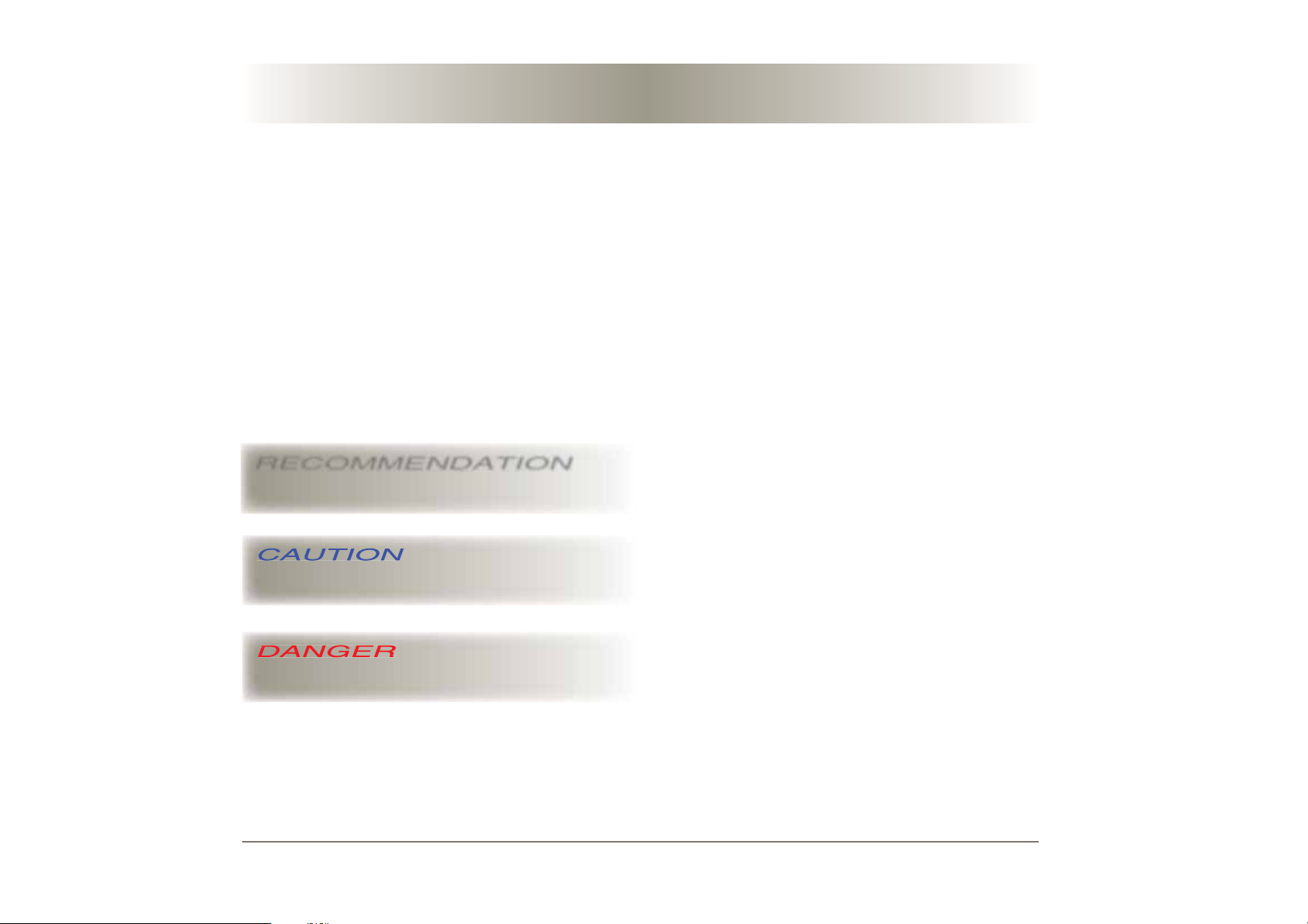
The different warnings used throughout this guide are as follows:
RECOMMENDATION
Before you put out to sea, please read the owner’s manual (CE standard manual) delivered with your boat and please follow
the instructions.
Shows a piece of advice to do the appropriate actions or
manoeuvres adapted to what you are thinking of doing.
Draws your attention on dangerous ways of doing that may
bring about injuries to people or damages to the boat or her
components.
Warns you about the existence of a hazard that may have
serious or fatal consequences if the appropriate precautions
are not taken.
Page 6

Page 7

Contents
5
1 Specifications
1.1 I D of your boat
1.2 Technical specifi cations
1.3 Wheelhouse helm description
1.4 Flying bridge control house description
1.5 24 V - 230 V electrical panel description
2 Hull / deck
2.1 Construction
2.2 Careening
2.3 Deck fi tting
2.4 Access to the boat
2.5 Cockpit
2.6 Flying bridge
2.7 Access to the crew cabin
2.8 Retractable sun awning
2.9 Deck wash pump
2.10 Swim ladder
2.11 Deck searchlight
2.12 Underwater spotlights
2.13 Capstan
2.14 Anchoring
2.15 Gangway
2.16 Hydraulic platform
3 Accommodations
3.1 Saloon table
3.2 Floorboards
3.3 Portholes - Deck hatches
3.4 Windows
3.5 Cabins
3.6 Helm stations
Page 07
Page 17
Page 35
4 Utility aboard
4.1 Slot-in television
4.2 Flying bridge refrigerator
4.3 Flying bridge grill
4.4 Icemaker
4.5 Microwave oven
4.6 Stove unit
4.7 Induction cooktop
4.8 Extractor hood
4.9 Refrigerator / freezer
4.10 Dishwasher
4.11 Washer dryer
4.12 Safe
4.13 Heating
4.14 Air conditionning
5 Water systems
5.1 Bilge pump system
5.2 Grey waters
5.3 Black waters
5.4 Fresh water
6 Electricity
6.1 24 V circuit
6.2 Inverters
6.3 230 V circuit
6.4 Electronics
Page 41
Page 55
Page 65
7 Propulsion
7.1 Engines
7.2 Fuel
7.3 Dash boards
7.4 Steering system
7.5 Demister
7.6 Trim tabs
7.7 Propellers and anodes
7.8 Bow thruster
8 Winter storage
8.1 Laying up
8.2 Protection
9 Handling
9.1 Preparation
9.2 Crane lifting
10 Safety
10.1 Prevention
10.2 Gas system
10.3 Fire
10.4 Bilge pump system
10.5 Safety equipments
10.6 General remarks
11 Maintenance
11.1 Maintenance schedule
Page 81
Page 93
Page 97
Page 101
Page 115
Code 136497 - Indice C
Page 8

Page 9

Specifications
1.1 I.D. of your boat
1.2 Technical specifications
1.3 Wheelhouse helm description
1.4 Flying bridge control house description
1.5 24 V - 230 V electrical panel description
1
7
Page 10

Page 11

Your boat
9
1
NAME OF YOUR BOAT: . . . . . . . . . . . . . . . . . . . . . . . . . . . . . . . . . .
VERSION: . . . . . . . . . . . . . . . . . . . . . . . . . . . . . . . . . . . . . . . . . . . .
DELIVERY DATE: . . . . . . . . . . . . . . . . . . . . . . . . . . . . . . . . . . . . . . .
REGISTRATION NUMBER: . . . . . . . . . . . . . . . . . . . . . . . . . . . . . . .
DOOR KEY NUMBER: . . . . . . . . . . . . . . . . . . . . . . . . . . . . . . . . . . .
HULL NUMBER: . . . . . . . . . . . . . . . . . . . . . . . . . . . . . . . . . . . . . . .
MAKE OF THE ENGINES: . . . . . . . . . . . . . . . . . . . . . . . . . . . . . . . .
NUMBERS OF THE ENGINE KEYS: . . . . . . . . . . . . . . . . . . . . . . . .
SERIAL NUMBER OF THE STARBOARD ENGINE: . . . . . . . . . . . . .
SERIAL NUMBER OF THE PORT ENGINE: . . . . . . . . . . . . . . . . . . .
FURTHER INFORMATION: . . . . . . . . . . . . . . . . . . . . . . . . . . . . . . .
. . . . . . . . . . . . . . . . . . . . . . . . . . . . . . . . . . . . . . . . . . . . . . . . . . . . .
OWNER’S NAME: . . . . . . . . . . . . . . . . . . . . . . . . . . . . . . . . . . . . . .
ADDRESS: . . . . . . . . . . . . . . . . . . . . . . . . . . . . . . . . . . . . . . . . . . . .
. . . . . . . . . . . . . . . . . . . . . . . . . . . . . . . . . . . . . . . . . . . . . . . . . . . . .
. . . . . . . . . . . . . . . . . . . . . . . . . . . . . . . . . . . . . . . . . . . . . . . . . . . . .
E-MAIL ADDRESS: . . . . . . . . . . . . . . . . . . . . . . . . . . . . . . . . . . . . .
LANDLINE PHONE NUMBER: . . . . . . . . . . . . . . . . . . . . . . . . . . . . .
MOBILE PHONE NUMBER: . . . . . . . . . . . . . . . . . . . . . . . . . . . . . . .
. . . . . . . . . . . . . . . . . . . . . . . . . . . . . . . . . . . . . . . . . . . . . . . . . . . . .
. . . . . . . . . . . . . . . . . . . . . . . . . . . . . . . . . . . . . . . . . . . . . . . . . . . . .
BP 529 - 85505 LES HERBIERS CEDEX - FRANCE - TEL +33 (0)2 51 64 20 20 - FAX +33 (0)2 51 67 37 65 - www.prestige-yachts.com
Page 12

10
Design categories
CATEGORY A
The boat is designed for sailing in winds that may exceed force 8 on the Beaufort Scale and in waves of a signifi cant height of 4m and more and the boat is
to a large extent self-suffi cient.
Unusual conditions such as hurricanes are excluded.
You may meet with such conditions when you sail long crossings, for instance
across the oceans, or close to the shore when you are not protected from the
wind or waves over several hundreds of nautical miles.
CATEGORY B
The boat is designed for sailing in winds that do not exceed force 8 on the
Beaufort Scale and in the corresponding waves (waves of a signifi cant height
inferior or equal to 4m).
You may meet with such conditions when you sail offshore or close to the
shore when you are not protected from the wind or waves over several dozens
of nautical miles. You may also meet with such conditions in inland seas of a
suffi cient size to be able to give the wave height in question.
CATEGORY C
The boat is designed for sailing in winds that do not exceed force 6 on the
Beaufort Scale and in the corresponding waves (waves of a signifi cant height
inferior or equal to 2m).
You may meet with such conditions in exposed inland waters, in estuaries and
in coastal waters with mild weather conditions.
CATEGORY D
The boat is designed for sailing in winds that do not exceed force 4 on the
Beaufort Scale and in the corresponding waves (occasional 0.5m high waves
at a maximum).
You may meet with such conditions in sheltered inland waters and in coastal
waters in fi ne weather.
NOTE :
The signifi cant height of a wave is the average height of the upper third of the
waves; this corresponds more or less to the height of a wave an experienced
observer can assess.
Some waves will be twice as high as this value.
Page 13
Technical specifications
11
1
Length overall (L. O. A.) . . . . . . . . . . . . . . . . . . . . . . . . . . . 15,20 m / 49'10"
Hull Length . . . . . . . . . . . . . . . . . . . . . . . . . . . . . . . . . . . . 14,92 m / 48'11"
Beam. . . . . . . . . . . . . . . . . . . . . . . . . . . . . . . . . . . . . . . . . . . 4,50 m / 14'9"
Air draft . . . . . . . . . . . . . . . . . . . . . . . . . . . . . . . . . . . . . . . . . 5,23 m / 17'1"
Draft . . . . . . . . . . . . . . . . . . . . . . . . . . . . . . . . . . . . . . . . . . . . 1,05 m / 3'5"
Light displacement . . . . . . . . . . . . . . . . . . . . . . . . . . . 14100 kg / 30080 lbs
Maximum load displacement . . . . . . . . . . . . . . . . . . . . 19862 kg / 43795 lbs
Manufacturer’s maximum recommended load . . . . . . . B/4900 kg - C/4950 kg
. . . . . . . . . . . . . . . . . . . . . . . . . . . . . . . . . . . . . . . .B/10805 lbs - C/10915 lbs
Fresh water capacity . . . . . . . . . . . . . . . . . . . . . . . . 2 x 318 l / 2 x 84 US gal
Black water capacity . . . . . . 120 l / 32 US gal + 50 l / 13 US gal / crew cabin
Fuel capacity . . . . . . . . . . . . . . . . . . . . . . . . . . . . . 2 x 650 l / 2 x 172 US gal
Refrigeration unit capacity 24 V . . . . . . . . . . . 218 l/galley - 80 l/fl ying bridge
. . . . . . . . . . . . . . . . . . . . . . . . . . 58 US gal/galley - 21 US gal/fl ying bridge
24 V BATTERY CAPACITY
Domestic system . . . . . . . . . . . . . . . . . . . . . . . . . . . . . . . . . . . . . 4 x 140 Ah
Engine system . . . . . . . . . . . . . . . . . . . . . . . . . . . . . . . . . . . . . . . . 4 x 50 Ah
Bow thruster . . . . . . . . . . . . . . . . . . . . . . . . . . . . . . . . . . . . . . . . . 4 x 55 Ah
12 V BATTERY CAPACITY
CE CATEGORY Maximum number of persons
A .................................................................................
B .........................................................................12 persons
C .........................................................................14 persons
D .................................................................................
Bottom surface: 52,5 m2 / 565 sq ft
Generator . . . . . . . . . . . . . . . . . . . . . . . . . . . . . . . . . . . . . . . . . . . 1 x 50 Ah
Maximum engine power . . . . . . . . . . . . . . . . . . . . . . . . . . . 2 x 435 HP (IPS)
Design category. . . . . . . . . . . . . . . . . . . . . . . . . . . . . . . . . . . . . . . . . . . B / C
Page 14
12
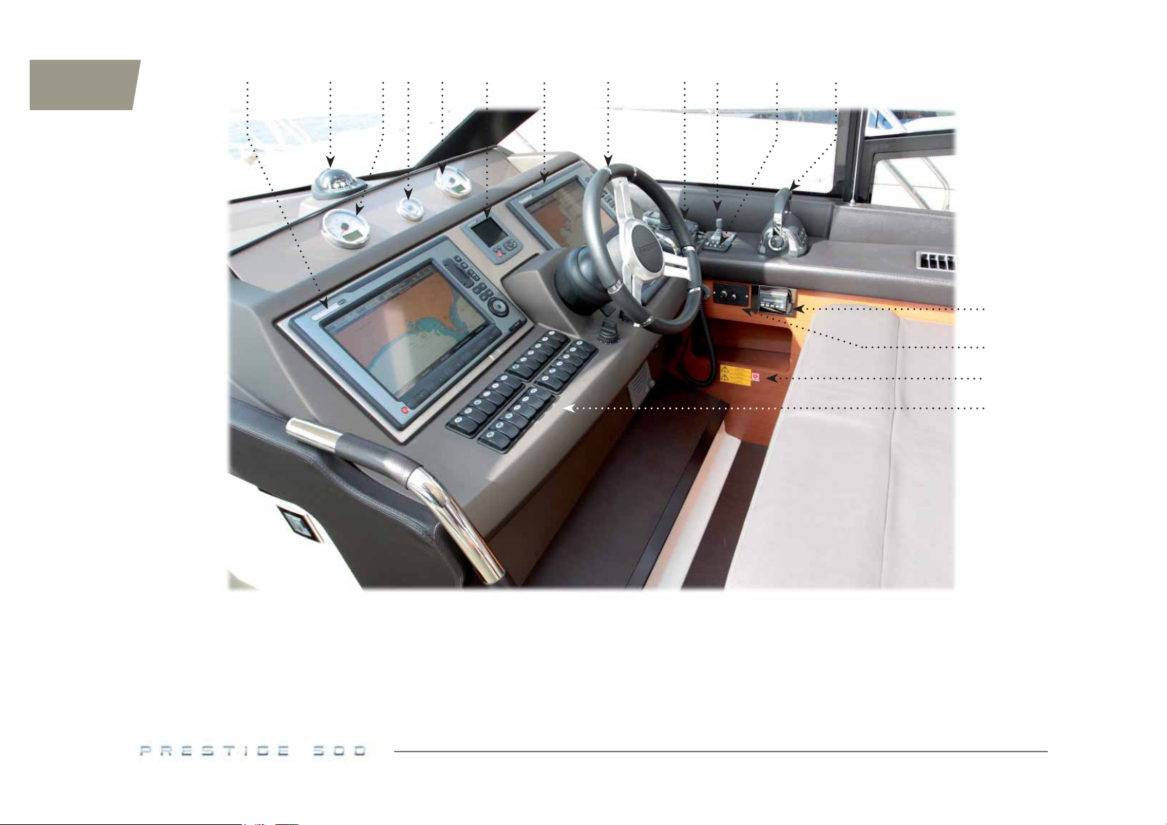
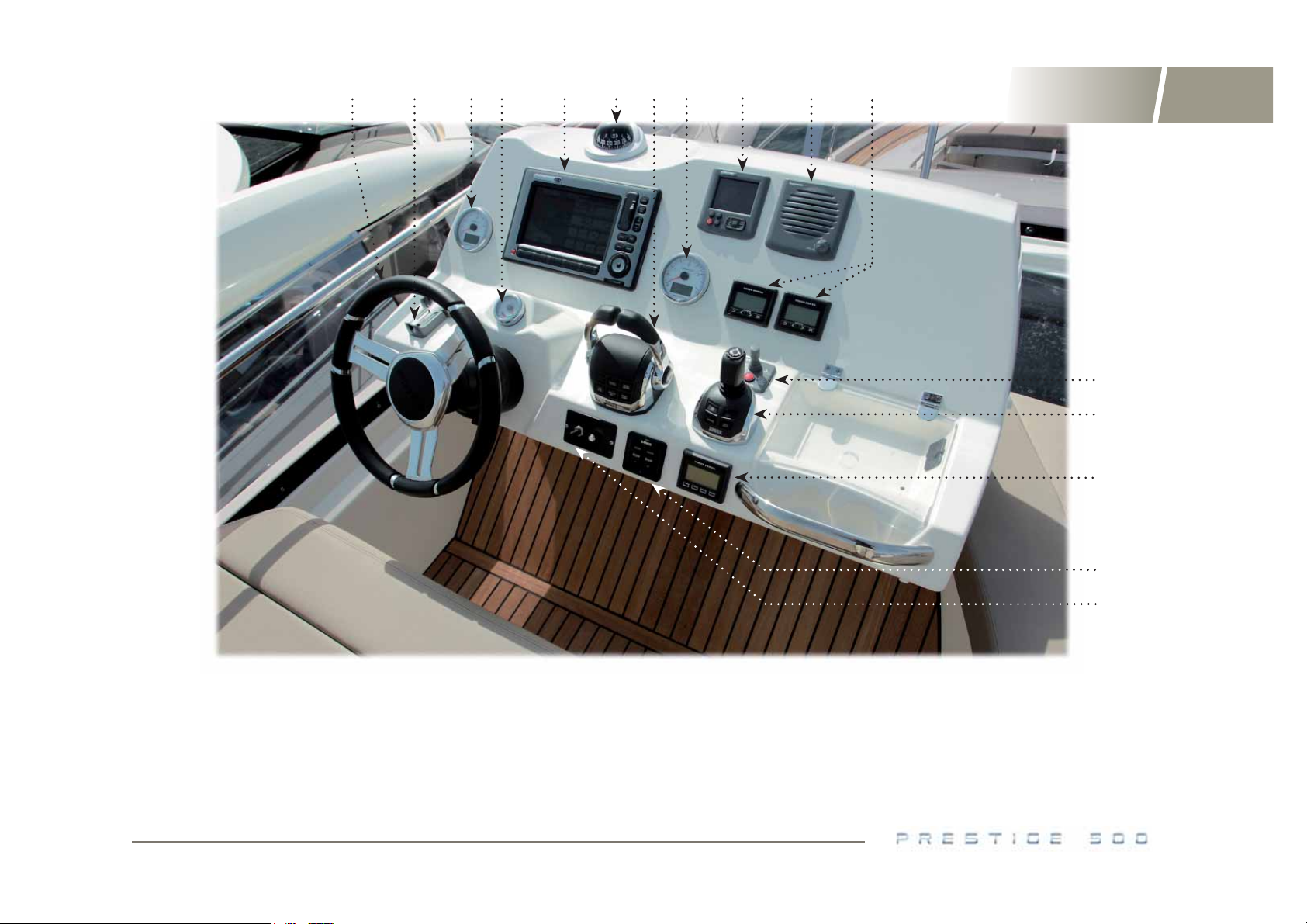
WHE ELHOUSE H ELM
2 3 4 51 7
1 1
6
8 9
10
11
12
13
14
1 - Screen/ repeater for the electronic system
(optional fi tting).
2 - Compass.
3 - Port engine rev counter.
4 - Rudder angle indicator.
5 - Starboard engine rev counter.
WHEELHOUSE HELM
6 - Adjustable steering wheel.
7 - VHF radio (optional fi tting).
8 - Bow thruster control (optional fi tting).
9 - Trim tab control.
10 - Engine controls.
11 - Air conditioning control (optional fi tting).
12 - Deck searchlight control (optional fi tting).
13 - Release pull handle of engine extinguisher.
14 - 24 V switches (for more details about their
functionalities, see p.66).
Page 15
2 3 4 51 96
FLYING BRIDGE C ONTROL HOUSE
8
7
5
10
13
1
11
12
13
1 - Adjustable steering wheel.
2 - VHF radio (optional fi tting).
3 - Port engine rev counter.
4 - Rudder angle indicator.
5 - Screen/ repeater for the electronic system
(optional fi tting).
FLYING BRIDGE CONTROL HOUSE
6 - Compass.
7 - Engine controls.
8 - Starboard engine rev counter.
9 - VHF loudspeaker (optional fi ttin).
10 - Engine control screens.
14
15
11 - Bow thruster control (optional fi tting).
12 - Joystick / engine controls (optional fi tting).
13 - Engine start / stop control unit.
14 - Trim tab control.
15 - Deck searchlight control (optional fi tting).
Page 16
14
1
2
34
5
6 89
7
10
11
12 13
14 15
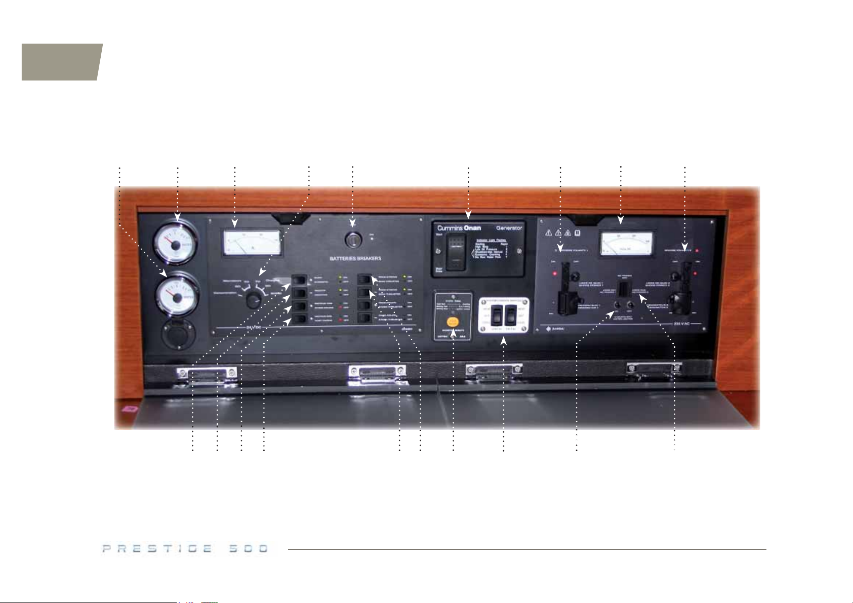
24 V - 230 V ELECTRICAL PANEL
16
17
18 19
Page 17

1
15
1 - Starboard water tank gauge.
2 - Port water tank gauge.
3 - Ammeter.
4 - Ammeter selector.
5 - General ON/OFF cut out.
6 - Generator control (optional fi tting).
7 - 230 V generator - shore supply selector / on board equipment.
8 - Voltmeter.
9 - 230 V generator - shore supply selector / air conditioning (optional fi tting).
LEGEND OF THE OPPOSITE PICTURE / 24 V - 230 V ELECTRICAL PANEL
10 - On board positive cut out.
11 - General negative cut out.
12 - Starboard engine positive cut out.
13 - Port engine positive cut out.
14 - Bow thruster positive cut out (optional fi tting).
15 - Bow thruster negative cut out (optional fi tting).
16 - 24 V / 230 V inverter control.
17 - Control to start the air conditioning.
18 - Water heater ON / OFF switches.
19 - 230 V selectors ON / OFF switches.
Page 18

Page 19

Hull / deck
17
2
2.1 Construction
2.2 Careening
2.3 Deck fitting
2.4 Access to the boat
2.5 Cockpit
2.6 Flying bridge
2.7 Access to the crew cabin
2.8 Retractable sun awning
2.9 Deck wash pump
2.10 Swim ladder
2.11 Deck searchlight
2.12 Underwater spotlights
2.13 Capstan
2.14 Anchoring
2.15 Gangway
2.16 Hydraulic platform
Page 20

18
Page 21

Hull / deck
2.1
Construction
The hull of the PRESTIGE 500 is made of laminate layers of fi breglass and
polyester resin with sandwich and an integrated osmosis barrier coat.
Frames and structural counter mould bonded and laminated to the hull, integrating supports for technical equipment: this is the way the structure of the
hull is.
The non structural areas maintain direct access to the hull.
The deck is made of laminate layers of fi breglass and polyester resin with
a sandwich composition suited to the different types of surfaces (fl at areas,
reinforced areas).
RECOMMENDATION
2.2
Careening
19
2
MAINTENANCE
The materials used to build your boat were selected for their high quality and
performances. Nevertheless they require a minimum maintenance to be protected from outside attacks (salt, sun, chafi ng, et...).
To keep her best look, besides her rinsing with fresh water after each trip, you
shall polish and shine the gel-coat periodically with cleaning products you will
buy at your dealer’s.
For possible stubborn stains or scratches, please contact your dealer; he will
be delighted to give you the proper advice.
A periodical careening of your boat will keep her original performances and
avoid any adhesion of marine vegetation.
The type of the water where you boat sails determines how to choose the
antifouling paint as well as how often to carry out these careenings.
Please contact a professional for advice.
Page 22
20
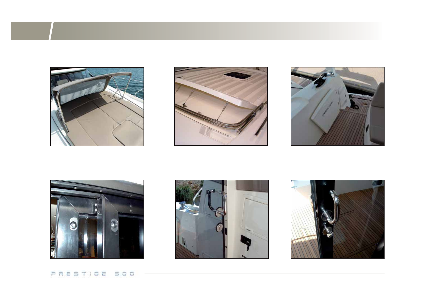
Fore deck - Access to the boat
OPEN CANOPY
SLIDING DOOR
STOPPING SYSTEM
SUNDECK
FOLDED CANOPY
SLIDING DOOR
LOCKING IT FROM THE OUTSIDE
GATE TO THE COCKPIT SUNDECK
SLIDING DOOR
LOCKING IT FROM THE INSIDE
Page 23

Hull / deck
2.3
Deck fitting
2.4
Access to the boat
21
2
FORE DECK
A sunbathing platform with a reclining back is integrated in the front desk,
protected by a foldable canopy.
Fasten the sundeck cushions and fold the canopy before you put out to sea.
PULPITS
Regularly rinse the stainless steel parts with fresh water.
LIFELINES
Inspect the metallic lifelines for "hairy wires".
Check for corrosion, particularly on the connections.
OUTSIDE WOODWORK
Regularly rinse and brush the outside woodworks with fresh water.
There are teak cleaners products on sale.
We advise you against using a pressure washer on teak.
AFT GATE
To come into the cockpit from the aft platform, lift the gate then push it to the
inside of the cockpit.
Be sure you closed the gate before you put out to sea.
WHEELHOUSE SLIDING GLASS DOOR
The wheelhouse has two sliding glass doors and a fi xed central part.
Each part slides and automatically stops at the end.
Unlock the different parts from the inside of the wheelhouse.
A curtain, inside the wheelhouse, covers the sliding glass door.
Page 24
22
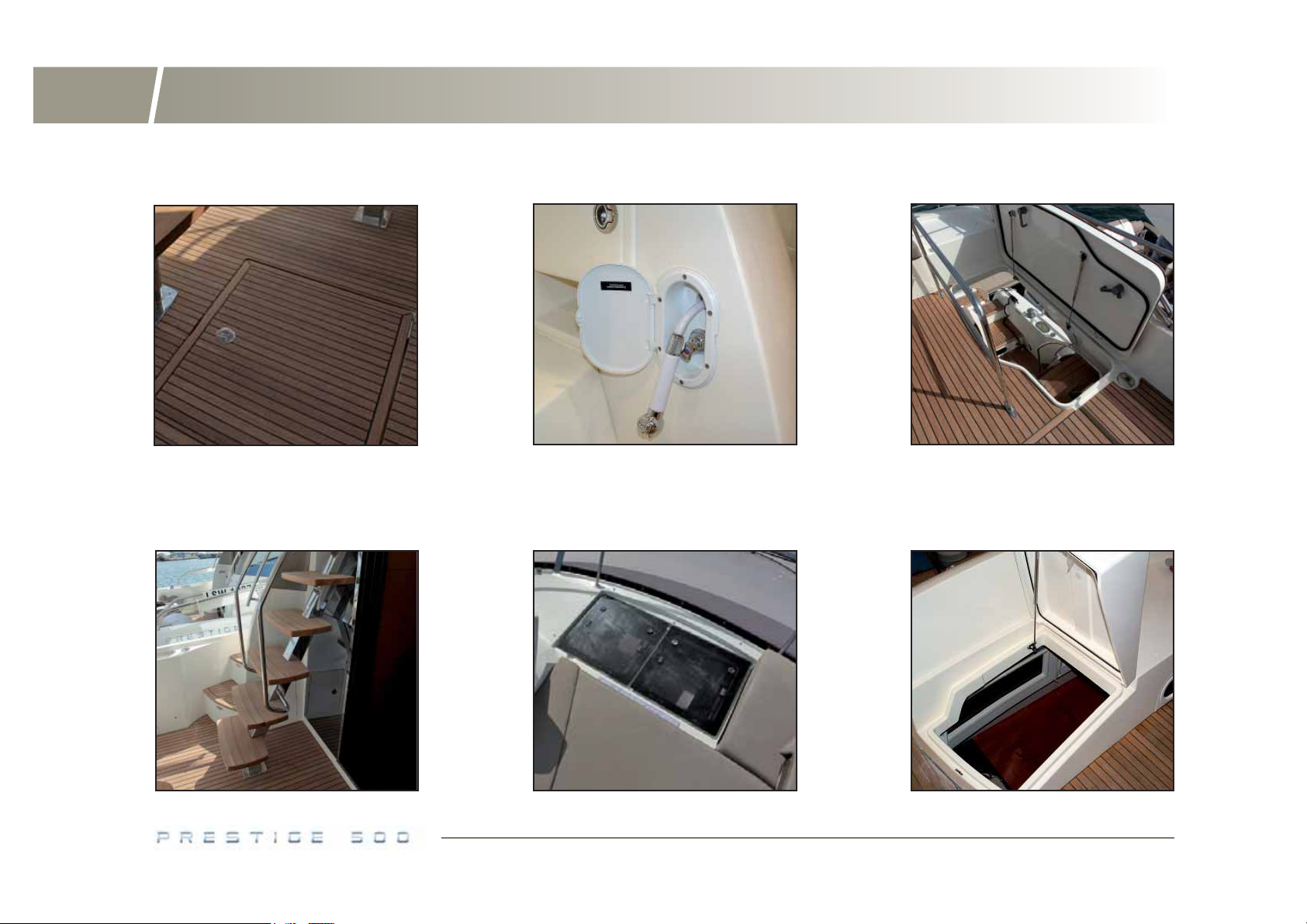
Cockpit locker - Flying bridge closing system
COCKPIT LOCKER COCKPIT SHOWER FLYING BRIDGE HATCH
ACCESS TO THE FLYING BRIDGE
FLYING BRIDGE
DESK HATCHES AND SUN DECK
ACCESS TO THE
CREW CABIN
Page 25

2.5
Cockpit
Hull / deck
2.6
Flying bridge
23
2
COCKPIT LOCKER
The cockpit is fi tted with a large locker with a companionway ladder.
You can reach the technical room and the engines using the ladder.
To open the cockpit locker, unlock it using the key, give the handle a quarter
turn then lift the latter.
COCKPIT SHOWER
The cockpit shower supplied with hot and cold water is located on the aft
starboard side of the cockpit.
Before using it, switch on the domestic 24 V circuit and the pressure water
pump using its switch on the dashboard.
ELECTRICAL AIR PUMP
The boat may optionally be fi tted with a portable electrical air pump.
Regarding the use and the maintenance of the electrical air pump, please
refer to the user’s manual.
You can go from the cockpit to the fl ying bridge using the stairs.
The fl ying bridge is fi tted with a hatch closing system set on jacks.
It is advisable to close the hatch cover when sailing.
FLYING BRIDGE SUNDECK
Fasten the cushions before going sailing.
FLYING BRIDGE HATCHES
Do not walk on the hatches.
Lock the hatches before going sailing.
2.7
Access to the crew cabin
The cockpit aft locker may be transformed into a crew cabin (optional fi tting).
You can reach the crew cabin from the cockpit through the cockpit seating
starboard side.
You can reach the pods through the fl oor in the crew cabin.
You can reach the battery chargers technical room through the back of the
cupboard.
Page 26
24
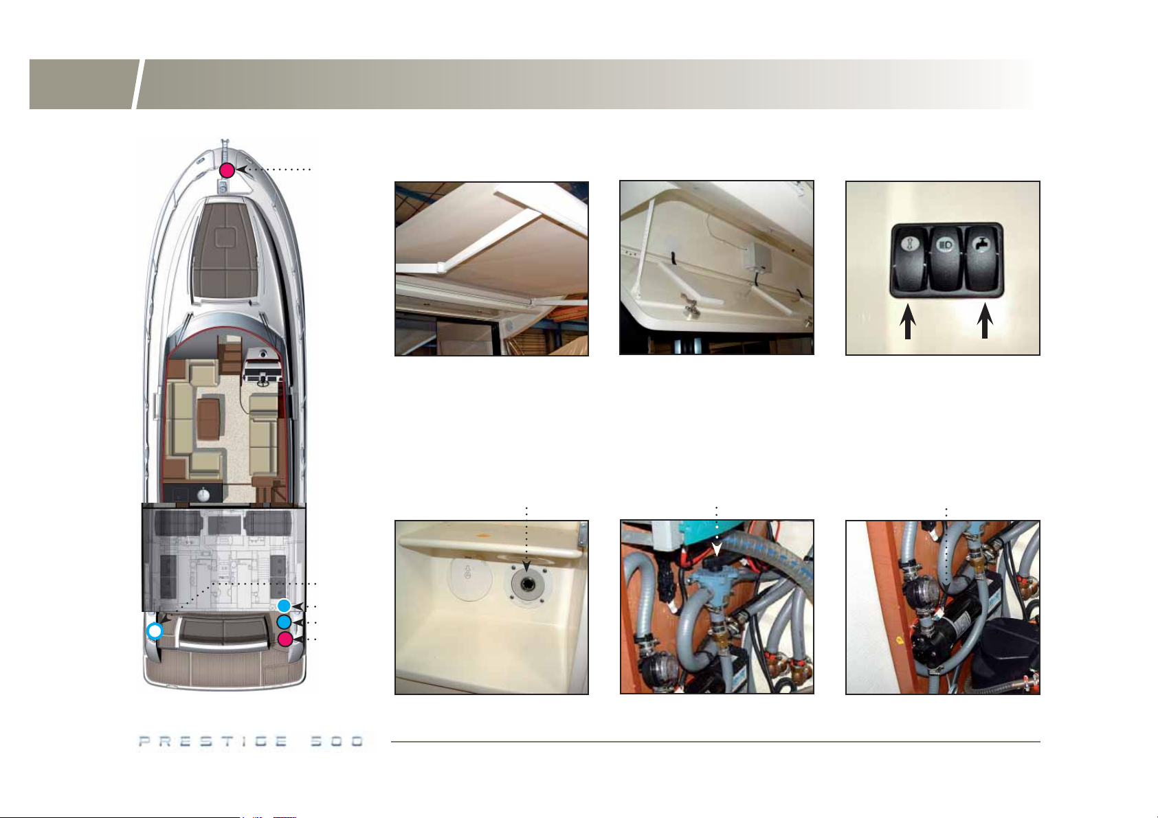
Retractable sun awning - Deckwash pump
RETRACTABLE
1
1 - Inlet to connect hose.
2 - Sea water supply valve.
3 - 3-way sea/fresh water selector valve.
4 - Deckwash pump.
SUN AWNING
1
UPPER COCKPIT LOCKER AWNING AND PUMP
SWITCHES
3
4
2
3
4
1
Page 27
Hull / deck
2.8
Retractable sun awning
2.9
Deckwash pump
25
2
The boat may optionally be equipped with a retractable sun awning fi tting in
the cockpit ceiling.
The retractable sun awning can be used only after having turned on the on
board 24 V circuit and the Comfort switch on the instrument panel.
To unfold the sun awning:
- Check that the on board electrical circuit has been turned on the instrument
panel located in the cupboard on the starboard side of the entrance.
- Unfold and then fold the retractable sun awning using its switch located on
the starboard side of the cockpit.
UPPER COCKPIT LOCKER
To open the locker:
- Unlock the three latches.
- Support the locker while it goes down.
RECOMMENDATION
The boat may optionally be fi tted with a deckwash pump.
The deckwash pump is located behind the ladder in the aft cockpit locker or
the crew cabin.
It provides sea water or fresh water from the tanks.
Open the sea water inlet valve (access through the trap located in the port
side toilets).
Select sea or fresh water using the valve located behind the ladder in the aft
cockpit locker or the crew cabin.
You can turn on the deckwash pump using the switch located on the cockpit
starboard side.
Press the plastic rims of the water inlets (starboard locker of aft platform +
anchor locker) to connect or disconnect the “Gardena” type connector.
Page 28
26
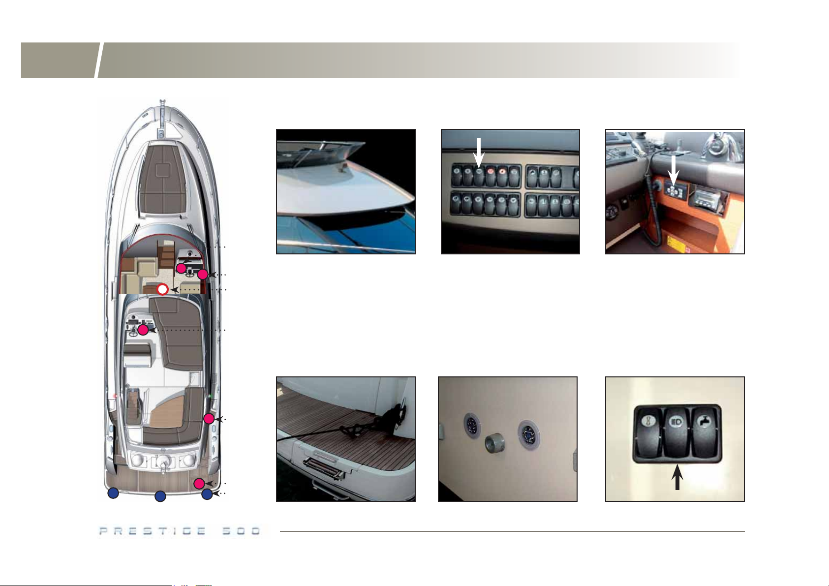
Swim ladder - Deck searchligh - Underwater spotlights
DECK SEARCHLIGHT
1
2
3
2
1 - Deck searchlight switch.
2 - Deck searchlight control.
3 - Underwater spotlights switch.
SWIM LADDER
DECK SEARCHLIGHT
SWITCH
4 - Deck searchlight.
5 - Swim ladder.
6 - Underwater spotlights.
UNDERWATER
SPOTLIGHTS
DECK SEARCHLIGHT
CONTROL
SWITCH OF THE
UNDERWATER SPOTLIGHTS
4
5
6
Page 29

Hull / deck
27
2
2.10
A swim ladder is located in the quarterdeck portside locker.
Do not forget to lift up the swimming ladder before sailing.
2.11
The boat may optionally be fi tted with a deck searchlight.
After having turned on the 24 V on board circuit, light on the deck searchlight
using its switch located on the command post instrument panel.
Use the control on the wheelhouse helm station or the fl ying bridge helm
station to operate the deck searchlight.
Swim ladder
Deck searchlight
2.12
The boat may be fi tted with optional underwater spotlights.
The underwater spotlights are under the aft platform, below the water line.
After having turned on the 24 V on board circuit and the Comfort switch on the
command post instrument panel, turn on the underwater spotlights using the
switch located on the starboard side of the cockpit.
Underwater spotlights
Page 30
28
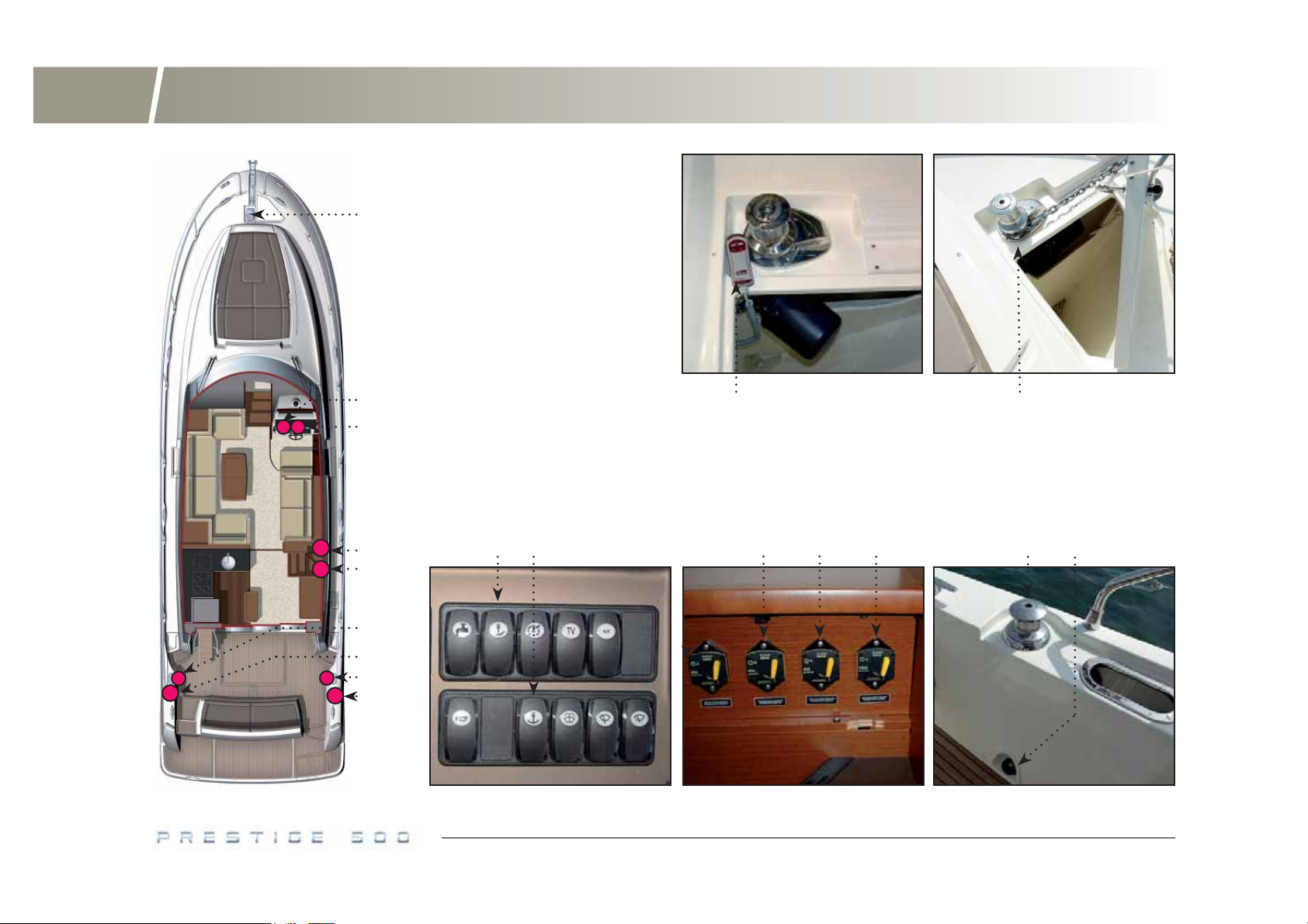
Electric windlass - Capstan
1 - Electric windlass.
1
2 - Windlass switch.
3 - Windlass control.
4 - Capstan automatic breaker.
5 - Windlass automatic breaker.
6 - Capstan foot control.
7 - Capstan.
8 - Windlass control.
2
3
3
4
5
6
7
6
7
2 75
2
8
4
4
1
6
Page 31

Hull / deck
29
2
2.13
The capstan foot control is located at the bottom of the cockpit starboard
side.
The capstan can be used after switching on the 24 V domestic circuit.
If it does not work, check its circuit breaker located in the locker of the starboard companion ladder.
For the use and maintenance of the capstan, please refer to its instruction
guide.
A second electric capstan can be chosen as an option.
2.14
The stem is fi tted with a stainless steel fi tting with a double roller which enables you to sail when the anchor is home.
The fore deck is fi tted with an electric windlass.
Capstan
Anchoring
ELECTRIC WINDLASS
The electric windlass can be used when one or two engines are operating.
Turn on the windlass using its switch located on the instrument panel.
Operate the windlass from the helm station in the wheelhouse or the fl ying
bridge or using the control in the anchor locker.
If the electric windlass does not work, check its circuit breaker located in the
locker of the starboard companion ladder.
ANCHORING WITH THE ELECTRIC WINDLASS
- Have your boat head wind and sail slowly.
- Operate the windlass downwards.
- Veer away the chain while moving back slowly.
- When the anchor holds, make the wrap fast on the cleat.
RECOMMENDATION
Once the boat is anchored, keep an eye on the swinging space.
Before you anchor, check the type of the sea bed, the depth of water and the
strength of the stream.
Slip the anchor at least 3 times the depth of water.
A quality anchoring depends on both the chain (its weight makes the boat
stabilize) and the anchor.
Page 32

30
Gangway
HYDRAULIC
GANGWAY
1 - Automatic breaker.
2 - Gangway control.
3 - Hydraulic pump.
4 - Gangway location.
2 31
1
GANGWAY
USED AS A CRANE
2
3
4
Page 33

Hull / deck
31
2
RAISING THE GROUND TACKLE
- Lock the grab brake.
- Check the chain is properly set on the grab.
- Activate the windlass setting it to the ‘upward’ position.
- Slowly go near the anchor using the engine (do not use the windlass force
to winch up the boat).
RECOMMENDATION
- Visually check the fi nal metres until the anchor gets into contact with the
anchor fairlead.
- Check the position of the anchor on the stem fi tting.
Rinse the windlass and the ground tackle with fresh water each time you
come back.
For the maintenance of the windlass, please refer to its instruction guide.
2.15
The boat may be fi tted with an optional hydraulic gangway.
After the domestic electrical system is switched on, the gangway can work.
The gangway control is located in the cockpit aft port side.
A remote control is also available on board the boat.
If it does not work, check its circuit breaker located in the locker of the starboard companion ladder.
If all else fails, it is possible to retract the gangway using the lever on its hydraulic pump (access through the aft cockpit locker or crew cabin, port side).
The gangway can also be used as a crane in order to lift a tender up to the
transom or to take it down to the water from the transom.
Gangway
For winter storage, release the windlass brake and make sure the grab turns
freely.
For the use and maintenance of the hydraulic gangway, please refer to its
instruction guide.
Page 34

32
Hydraulic platform
HYDRAULIC
PLATFORM
1 - Platform automatic breaker.
2 - Platform control.
3 - Hydraulic pump.
1
2
3
2 31
Page 35

Hull / deck
33
2
2.16
The aft swim platform can be equipped as an option with an hydraulic platform.
Hydraulic struts enable you to let it down under the boat waterline.
After switching on the domestic 24 V circuit, use the platform control located
in the cubby hole on the starboard side of the cockpit.
The control makes it possible to lower, raise the platform into any position or
stop it in the chosen position.
In order to keep the platform in good working order, set the load as close as
possible to its centre.
Hydraulic platform
If it does not work, check its breaker located in the cubby hole in the companionway down to the aft cabin.
If all else fails, it is possible to raise the aft platform using the lever on its
hydraulic pump located in the service compartment located under the bed in
the skipper’s cabin.
Nota : a specifi c gangway is provided for boats equipped with the optional
hydraulic platform. It supports a maximum weight of 150 Kg.
RECOMMENDATION
Page 36

Page 37

Accommodations
3.1 Saloon table
3.2 Floorboards
3.3 Portholes - Deck hatches
3.4 Windows
3.5 Cabins
3.6 Helm stations
35
3
Page 38

36
Saloon table - Windows - Blinds
SALOON TABLE
SHORT POSITION
BLIND + MOSQUITO SCREEN
DECK HATCH
SALOON TABLE
LONG POSITION
SALOON TABLE FLOOR
FASTENING
BLIND ON
WHEELHOUSE WINDOW
Page 39

Accommodations
3.1
Saloon table
3
3.3
Portholes - Deck hatches
37
The saloon table can articulate into two positions, a short one when folded, a
long one when unfolded.
To extend the table:
- Take out the leaf brackets located on both sides, under the table.
- Unfold the two table tops.
Follow the procedure in the inverse order to convert the table into short position.
The saloon table can be moved unscrewing the two bolts located in between
the table legs.
3.2
Floorboards
The cabin fl oorboards have hatches to have access to the different service
units onboard, such as the waste holding tank, the windscreen washer tank
under the front cabin fl oor or a fresh water tank under the passageway fl oor.
RECOMMENDATION
The portholes and deck hatch are fi tted with locking systems to keep them in
a closed position.
At anchor, intermediate opening positions allow for airing the boat.
The deck hatches are fi tted with a blind and mosquito screen system that can
be used even when the hatch is open.
Their handling shall be done carefully.
3.4
Windows
CURTAINS
The windows in the wheelhouse, cabins and heads have blinds.
The wheelhouse blind can be electrically controlled (optional fi tting).
The electric blinds are controlled independently whether they are on the port
on the starboard side.
Another optional fi tting allows to equip the boat with outside blinds, obscuring
then all the wheelhouse.
Page 40

38
Sliding window - Cabins - Windscreen washer
SLIDING WINDOW
CREW CABIN WET ROOM
SLIDING WINDOW
CONTROLS
ADJUSTABLE
STEERING WHEEL
TWO-BERTH
PORT SIDE CABIN
WINDSCREEN WASHER
AND WIPERS SWITCHES
DOUBLE BED
PORT SIDE CABIN
WINDSCREEN
WASHER TANK
Page 41

Accommodations
39
3
ELECTRICAL SLIDING WINDOWS
The wheelhouse has two electrical sliding windows located next to the command post.
After having turned on the on board electrical system and the Comfort switch
on the instrument panel, you can make the windows go up or down using the
switched located on the station on the left of the command post.
3.5
Cabins
FRONT CABIN
The berth in the front cabin can be divided into two separated berths.
Lift each part of the berth and slide them towards the hull.
PORT SIDE CABIN
The two berths of the port side cabin can be transformed into one double bed
only by adding cushions in between them.
3.6
Helm stations
WHEEL
The height of the wheel can be adjusted to ease steering when you are standing or sitting.
DASH BOARD
All the desks and switches necessary for the engine and comfort component
operation are on the dash board.
Please read the details about the switches in Chapter ELECTRICITY.
WINDSCREEN WIPERS
The boat is fi tted with two windscreen wipers with incorporate windscreen
washer.
Windscreen wipers can be used having turned on the Comfort switch.
Their control is located on the left part of the wheelhouse instrument panel.
CREW CABIN
As an optional fi tting, the aft technical room can be transformed into a crew
cabin.
The crew cabin is fi tted with a simple berth, a private wet room and marine
toilets.
WINDSCREEN WASHER
The windscreen washer tank is located under the fl oor in front of the bed in
the front cabin.
Operate the windscreen washer using its switch located on the command post
instrument panel.
Page 42

Page 43

On board utility
41
4
4.1 Slot-in television
4.2 Flying bridge refrigerator
4.3 Flying bridge grill
4.4 Icemaker
4.5 Microwave oven
4.6 Stove unit
4.7 Induction cooktop
4.8 Extractor Hood
4.9 Refrigerator / freezer
4.10 Dishwasher
4.11 Washer-dryer
4.12 Safe
4.13 Heating
4.14 Air conditioning
Page 44

42
Slot-in television - Flying bridge refrigerator and grill
SLOT-IN TELEVISION UP / DOWN TV SWITCH
1
2
3
1 - Television.
2 - Up / down television switch.
3 - Utility switch.
FLYING BRIDGE GRILL
4
5
6
4 - Flying bridge grill.
5 - Flying bridge refrigerator.
6 - Refrigerator compressor.
REFRIGERATOR
INVERTER CONTROL
UTILITY SWITCHFLYING BRIDGE
Page 45

On board utility
4.1
Slot-in television
4.2
Flying bridge refrigerator
43
4
According to the lay out, the saloon is fi tted with a slot-in television located in
the unit at the front of the saloon.
After having turned on the 24 V circuit, use the Utility switch on the instrument
panel and then the switch located in companion ladder next to the command
post to make the television go up or down.
RECOMMENDATION
The TV set is powered through a 24 V / 230 V converter located in the port
technical room (see chapter ELECTRICITY).
RECOMMENDATION
For the use and maintenance of the television, please refer to its instruction
guide.
Nota: front or back cabins can also be fi tted with TV sets. Each of them is
supplied with the 24 V / 230 V converter.
The boat is fi tted with a fl ying bridge refrigerator.
It can be used after having turned on the 24 V on board circuit and after having
activated the Comfort switch.
Start the refrigerator using the thermostat switch.
Defrost then drain the refrigerator before you stop the domestic 24 V circuit.
For the use and maintenance of the fl ying bridge refrigerator, please refer to
its instruction guide.
4.3
Flying bridge grill
The boat is fi tted with an electric grill on the fl ying bridge.
Check that its circuit breaker has been powered on the lower bus in the electrical panel located in the companion ladder, next to the aft cabin.
SUPPLY
Select the source of the supply (generator or shore power) using the left selector of the 230 V selection panel at the entrance of the wheelhouse.
Page 46

44
Icemaker - Microwave oven
230 V ELECTRICAL CABINET
1
2
3
1 - Microwave oven.
4
2 - 230 V electrical cabinet.
3 - Icemaker.
4 - 230 V electrical panel.
5 - Valve + fi lter of the icemaker.
ICEMAKER VALVE + FILTER
OF THE ICEMAKER
MICROWAVE OVEN
5
Page 47

On board utility
For the use and maintenance of the fl ying bridge electric grill, please refer to
its instruction guide.
4.4
Icemaker
The boat is optionally fi tted with an icemaker located in the wheelhouse starboard entrance cupboard.
It is supplied with water coming from the fresh water system (valve located
above the fi lter in the starboard technical room).
4
4.5
Microwave oven
The boat is fi tted with a microwave oven located in the galley.
Check that its circuit breaker has been powered on the lower bus in the electrical panel located in the companion ladder, next to the aft cabin.
SUPPLY
Select the source of the supply (generator or shore power) using the left selector of the 230 V selection panel at the entrance of the wheelhouse.
For the use and maintenance of the microwave oven, please refer to its instruction guide.
45
Check that its circuit breaker has been powered on the lower bus in the electrical panel located in the companion ladder, next to the aft cabin.
SUPPLY
Select the source of the supply (generator or shore power) using the left selector of the 230 V selection panel at the entrance of the wheelhouse.
For the use and maintenance of the icemaker, please refer to its instruction
guide.
Nota: The icemaker system is fi tted with a carbon fi lter which is in the service
room. Regularly change the carbon fi lter.
Page 48

46
Stove unit - Induction cooktop - Hood
1
2
1 - Stove unit or
3
induction cooktop.
4
2 - 230 V electrical cabinet.
5
3 - Gas valves.
6
4 - 230 V electrical panel.
5 - Extractor hood.
6 - Storage place for gas bottles.
STORAGE PLACE FOR
GAS BOTTLES
INDUCTION
COOKTOP
GAS VALVESSTOVE UNIT
EXTRACTOR HOOD
Page 49

On board utility
47
4
4.6
Stove unit
The boat standard features include a 3-burner stove unit.
The burners run on gas after having opened the dedicated valve located under
the microwave (access through the drawer under the oven).
After turning on the burners, a safety feature obliges you to keep the knobs
pressed during a few seconds.
The gas cartridges are located in a storage space which you can gain reach
on the starboard side of the stairs leading to the fl ying bridge.
4.7
Induction cooktop
According to the fi tting out, the boat may optionally be fi tted with a induction
cooktop located in the kitchen and replacing the stove unit.
For the use and maintenance of the induction cooktop, please refer to its
instruction guide.
4.8
Extractor Hood
The boat is fi tted with an extractor hood located in the galley.
Check that its circuit breaker has been powered on the upper bus in the electrical panel located in the companion ladder, next to the aft cabin.
SUPPLY
Select the source of the supply (generator or shore power) using the left selector of the 230 V selection panel at the entrance of the wheelhouse.
For the use and maintenance of the extractor hood, please refer to its instruction guide.
Check that its circuit breaker has been powered on the upper bus in the electrical panel located in the companion ladder, next to the aft cabin.
SUPPLY
Select the source of the supply (generator or shore power) using the left selector of the 230 V selection panel at the entrance of the wheelhouse.
Page 50

48
Refrigerator - Dishwasher - Washer-dryer
1
2
3
4
5
6
7
8
9
10
UTILITY SWITCH
1 - Washer-dryer outlet.
2 - Washer-dryer.
3 - Utility switch.
4 - Washer-dryer fresh water
supply valve.
5 - Dishwasher.
6 - Dishwasher fresh water
supply valve.
7 - 230 V electrical cabinet.
8 - Refrigerator / freezer.
9 - 230 V electrical panel.
10 - Diswasher outlet.
DISHWASHER DISHWASHER - FRESH
WATER SUPPLY VALVE
WASHER-DRYER WASHER-DRYER - FRESH
WATER SUPPLY VALVE
Page 51

On board utility
49
4
4.9
Refrigerator / freezer
The boat is fi tted with a refrigerator / freezer located in the galley.
After having turned on the 24 V on board circuit, activate the Comfort switch
on the instrument panel.
Start the refrigerator using the thermostat switch.
Defrost then drain the refrigerator / freezer before you stop the domestic 24 V
circuit.
For the use and maintenance of the refrigerator / freezer, please refer to its
instruction guide.
4.10
The boat is fi tted with an optional dishwasher located in the galley.
The fresh water system supplies it with water.
Check that the relevant fresh water inlet valve located in the bin locker next to
the dish washer is open.
The drainage is direct (valve located in the port side technical room).
Check that its circuit breaker has been powered on the lower bus in the electrical panel located in the companion ladder, next to the aft cabin.
Dishwasher
SUPPLY
Select the source of the supply (generator or shore power) using the left selector of the 230 V selection panel at the entrance of the wheelhouse.
RECOMMENDATION
For the use and maintenance of the dishwasher, please refer to its instruction
guide.
4.11
The boat may optionally be fi tted with a washing machine located under the
front companion ladder.
The fresh water system supplies it with water.
Check that the relevant fresh water inlet valve located behind the washing
machine is open.
The drainage is direct (valve located in the front bathroom).
Check that its circuit breaker has been powered on the lower bus in the electrical panel located in the companion ladder, next to the aft cabin.
SUPPLY
Select the source of the supply (generator or shore power) using the left selector of the 230 V selection panel at the entrance of the wheelhouse.
Washer-dryer
Page 52

50
Safe - Heating
HEATING CONTROL BOILER
1
2
1
1
2
3
1
4
5
6
1
1 - Forced air heater.
2 - Heating control.
3 - Safe.
4 - Fuel tank.
5 - Fuel valve.
6 - Boiler.
SAFE
1
2
1
2
1
Page 53

On board utility
51
4
RECOMMENDATION
For the use and maintenance of the washer-dryer, please refer to its instruction guide.
4.12
The boat may optionally be fi tted with an electronic safe, located in the aft
cabin, in the starboard locker.
For the use and maintenance of the safe, please refer to its instruction guide.
Safe
4.13
The boat may be fi tted with optional heating.
It is a system in closed circuit, that works with water circulation.
The heating works after switching on the 24 V circuit.
The boiler is located in the technical room, at the back of the port side fuel
tank.
It is fed from the port fuel tank.
- Check the fuel valve is open (access on the tank in the technical room to
port).
- Check and read the pressure on the manometer (please refer to the manufacturer’s guide).
Each part has a control and thermostat.
The front control cabin supplies the front cabin and the front bathroom.
The aft cabin control supplies the aft cabin and the aft bathroom.
For the use and maintenance of the heating system, please refer to its instruction guide.
Heating
Page 54

52
Air conditioning
1
2
3
2
1
3
2
3
1
1 - Outlet.
2 - Air conditioning control.
3 - Forced air heater.
4 - Automatic breaker of the
air conditioning components.
8
5 - Water inlet valves + fi lters.
6 - Air conditioning drain valves.
7 - Air conditioning unit.
8 - Hot / cold selector.
2
1
1
3
2
3
1
2
4
5
6
7
5
3 7
8
Page 55

On board utility
53
4
4.14
The boat may be fi tted with an optional reversible air conditioning system.
The air conditioning system requires 230 V with a cold water system.
Six air conditioning units (forced air heaters) work independently.
They are located:
- In the saloon, under the pilot seat and the port side aft saloon seating.
- In the front cabin (starboard locker).
- In the port cabin (wardrobe).
- In the aft cabin (starboard locker).
- In the crew cabin (locker located behind the companion ladder).
There are outlets in every cabin, in the galley and in the saloon.
Before you start the system:
- Open the seawater inlet valves in the technical room, behind the fuel tanks
(access through the cockpit locker).
- Open the seawater outlet valves located next to each group and in the technical room for the saloon groups.
Air conditioning
SUPPLY
Select the source of the supply (generator or shore POWER) using the right
selector of the 230 V selection panel at the entrance of the wheelhouse.
Check that the air conditioning group and the pump circuit breakers have
been powered on the upper and lower bus in the electrical panel located in
the companion ladder, next to the aft cabin.
After selecting hot or cold position using the switch in the electrical panel of
the chart table, start the air conditioning unit in the desired area then adjust
the temperature using its control switch.
Regularly clean the fi lter on the sea water suction valves.
For the use and maintenance of the air conditioning system, please refer to
its instruction guide.
The air conditioning units are called “reversible” as they can heat the boat if
the sea water temperature is over 10° C.
A dehumidifi er function can be preset on the air conditioning controls.
Page 56

Page 57

Water systems
5.1 Bilge pump system
5.2 Grey waters
5.3 Black waters
5.4 Fresh water
55
5
Page 58

56
Water system - Draining
1 - Electric bilge pump.
2 - Bilge pump outlet valve.
3 - Front wet room outlet valve.
4 - Aft wet room outlet valve.
5 - Shower pumps.
1
2
3
6 - Kitchen grey water outlet valves.
7 - Flying bridge sink drain valve.
8 - Manual bilge pump.
9 - Switches of the bilge pumps.
4
5
1
6
7
2
8
2
1
8
1
9
9 9
Page 59

Water systems
57
5
5.1
Bilge pump system
The boat is fi ttted with three electric bilge pumps:
- In the front cabin (under the fl oor in front of the door).
- In the aft cabin (under the trap under the starboard berth).
- In the crew cabin (under the berth).
A manual emergency pump is located on the starboard side of the cockpit in
front of the wheelhouse.
All the electric bilge pumps are switched on using the WATER PUMP switch on
the left on the dash board (They automatically start).
Each pump starts manually using the switches on the left on the dash board.
The pump automatically starts if the water level is low but the alarm does not
(Draining of the bilge pipes).
Then the alarm starts when the water level is higher.
Nota: the electric bilge pump located in the crew cabin functions automatically even when the 24 V circuit is turned off.
RECOMMENDATION
RECOMMENDATION
Nota: A valve is closed when its handle is perpendicular to the hose and it is
open when its handle is in line with the hose.
5.2
Grey waters
The grey waters coming from the showers, the washbasins and the sinks are
directly drained out via sea-cocks fi tted with valves.
Open the relevant valves before using the water equipment and close the
valve after use.
Page 60

58
Holding tank
1
2
3
4
5
1 - Holding tank.
2 - Drain valve of the tank.
3 - Gauge of the holding tank.
4 - Switch to drain the tank.
5 - Drain fi ller of the black waters.
6 - WATER PUMP switch.
7 - Device to switch on the pressure
water pump.
3 4 6 7
SWITCH OF
THE ELECTRIC TOILETS
5
1
2
HOLDING TANK
FRONT CABIN
HOLDING TANK
CREW CABIN
Page 61

Water systems
59
5
5.3
Black waters
The boat is fi tted with electric toilets and a 120 litres holding tank under the
fl oorboard, in front of the bed.
The WC working is based on a depression draining system and the use of the
domestic fresh water for rinsing (approximately 0,6 litre per rinse).
The crew cabin (optional fi tting) is fi tted with manual toilets and with a 50
litres black water tank located in the port side technical room.
USE OF THE MANUAL TOILETS (CREW CABIN)
- Open the water inlet and drain valves (under the wet room cabinet).
To empty the bowl:
- Set the control lever of the pump slantwise (FLUSH) and operate the pump.
To dry the bowl:
- Set the lever back vertical (DRY) and operate the pump.
In order to avoid clogging the toilets, use absorbent paper only and pump until
the emptying hose is completly empty.
Regularly rinse the toilets with fresh water.
Close the valves after each use.
USE OF THE ELECTRIC TOILETS
Check fi rst that the WATERPUMP and water group switches located on the
instrument panel are activated.
The FULL switch allows to fi ll up the bowl before use.
The QUICK FLUSH switch allows to rinse and fi ll up the bowl after light use.
The FLUSH switch allows to rinse and fi ll up the bowl twice after intense use.
The EMPTY switch allows to drain off the bowl only.
USE OF THE HOLDING TANKS
Watch the black water level using the gauge located next to the electrical
toilet, in the front wet room.
The black water tank in the front wet room is emptied by an electric pump.
The crew cabin black water tank is emptied by gravitational force.
Make sure the drain valve of the tank is closed in order to avoid any inadvertent discharge (the valve is closed when the handle is perpendicular to the
hose).
Tank drainage:
- In an authorized area, after switching on the domestic 24 V circuit and opening the drain valve located in the front wet room, drain the tank using the
switch located in the front wet room.
Concerning the tank located in the technical room, open the outlet valve.
Page 62

60
Fresh water system
1
2
3
4
5
1 - Fresh water tanks.
2 - Valves to select tanks.
3 - Pressure water pump.
4 - Deck fi ller.
5 - Tank gauges.
6 - Switch to start the pressure
water pump.
5
6
32
Page 63

Water systems
61
5
- In a marina equipped with an organic waste suction system, fi t the suction
hose into the tank through the deck fi ller located on the port side of the passageway, next to the wheelhouse door.
- Start the pump of the suction system.
Regularly rinse the holding tank.
RECOMMENDATION
5.4
Fresh water
FRESH WATER TANKS
The boat is fi tted with two 318 litres tanks located under the fl oor of the port
side cabin and of the fl oor.
They are fi lled by one single deck fi ller located in front of the port side deck.
Tank selector valves are located under the starboard berth of the port cabin.
During fi lling, avoid handling contaminants near the fi llers.
Open and close the fi ller caps with the right key.
Check the fi ller cap seals for condition during fi lling.
The tanks are fi tted with overfl ow outlets and vents.
Never insert the water fi lling hose deep down into the system in order to prevent any over-pressure in the systems.
RECOMMENDATION
Nota: the capacity of the fresh water tank(s) indicated on the page SPECIFICATIONS may be not completely usable depending on the trim and load of the
boat.
PRESSURE WATER PUMP
The water group is located under the starboard berth of the portside cabin.
Its starting is done by using a switch on the dash board.
RECOMMENDATION
To prevent any handling mistake, never fi ll the water and fuel tanks at the
same time.
Page 64

62
Shore fresh water supply - Water heater
SHORE FRESH
WATER SUPPLY
1
2
3
1 - Water heater.
2 - 230 V electrical cabinet.
3 - Switch of the water heater.
4 - Shore fresh water supply.
230 V ELECTRICAL CABINET
WATER HEATER
ON / OFF SWITCH
OF THE WATER HEATER
WATER HEATER
ENGINE VALVES
4
Page 65

Water systems
63
5
WATER GAUGE
Watch the level of the water in the tanks using the gauges located on the
electrical panel at the entrance of the wheelhouse.
The gauges work only after switching on the ‘Pressure Water Pump’ switch
on the dash board.
SHORE FRESH WATER SUPPLY
The fresh water inlet valve with pressure regulator is located in the starboard
aft cockpit locker.
To use the marina fresh water:
- Connect the shore supply.
- Set the pressure water pump switch to OFF.
RECOMMENDATION
WATER HEATER
The water heater has a capacity of 60 litres.
It is located under the aft cabin berth.
Check that its circuit breaker has been powered on the upper bus in the electrical panel located in the companion ladder, next to the aft cabin.
Two valves located ahead of the port engine make possible to leave the water
heater system apart from the engine one.
SUPPLY
If the engines are not running, Select the source of the supply (generator or
shore power) using the left selector on the 230 V selection panel at the entrance of the wheelhouse.
RECOMMENDATION
The hot water temperature is pre-set using the thermostatic tap located on
the water heater (access under the aft cabin berth).
The water heater works automatically once the engines are running, or on 230 V
supply after the shore power supply is plugged or after the generator started
and its switch on the electrical panel at the entrance of the wheelhouse is set
to ON.
Page 66

Page 67

Electricity
6.1 24 V circuit
6.2 Inverters
6.3 230 V circuit
6.4 Electronics
65
6
Page 68

66
24 V circuit location - Batteries - Electrical panel
1
2
3
4
5
6
7
8
9
10
BATTERY CHARGERS24 V ON BOARD
POWER UNIT
1 - Dash board.
2 - 230 V devices circuit breakers.
3 - Boat and engine cutouts.
4 - Electrical panel.
5 - 24 V / 230 V inverter.
6 - 24 V service power unit.
7 - Automatic breakers of the shore power sockets.
8 -
Engine 24 V batteries.
9 - Battery chargers.
10 - Shore power sockets.
ELECTRICAL PANEL
24 V CUTOUTS
31
2
1 - Ammeter.
2 - Domestic positive pole.
3 - Common negative pole.
4 - Starboard engine.
5 - Port engine.
6 - Bow thruster positive cut out.
7 - Bow thruster negative cut out.
45 67
Page 69

Electricity
67
6
6.1
24 V circuit
24 V CIRCUIT
TO SWITCH ON THE 24 V CIRCUIT
On the electrical panel at the entrance of the wheelhouse:
- Set the key to ON.
- Press the following switches: Board, Negative, Engines and Bow thruster.
- Keep them pressed two seconds.
The ON indicator lights are on.
TO SWITCH OFF THE 24 V CIRCUIT
On the electrical panel at the entrance of the wheelhouse:
- Press the following switches: Board, Negative, Engines and Bow thruster.
- Keep them pressed two seconds.
The OFF indicator lights are on.
- Set the key to OFF.
BATTERIES
The 24 V power unit supplying the board is located under the fl oor, port side,
in the technical room.
BATTERY RECHARGING
You recharge the battery bank either with two alternators (24 V / 80 Amp) or
with the battery charger (230 V / 24 V - 60 Amp).
Another battery charger (230 V / 24 V - 40 Amp) is dedicated to the bow
thruster battery park.
OPERATION
The battery chargers can be used with the shore power socket or the operating generator.
Check that the relevant circuit breaker has been powered on in the electrical
panel located in the companion ladder, next to the aft cabin or on the electric
panel in the starboard technical room for the thruster.
Select the source of the supply (shore power or generator) using the left selector on the 230 V selection panel at the entrance of the wheelhouse.
Nota: the battery chargers can remain in operation even when the boat is not
energized in 24 V.
CHECKING OF THE 24 V CONSUMING APPLIANCES
You can check the 24 V consuming appliances reading related data on the
dash board and the electrical panel at the entrance of the wheelhouse (read
details on the summary table at the end of this chapter).
Page 70

68
24 V switches - Shore power sockets - Inverter
6
54321 121110987
54321 9876 10
1 - Port side electric window.
2 - Navigation lights.
3 - Starboard side electric window.
4 - Mooring lights.
5 - Demister.
6 - Deck fl oodlight.
THE SHORE POWER SOCKETS
7 - Bilge pump.
8 - Lighting.
9 - Bilge pump.
10 - On board utility.
11 - Bilge pump.
12 - Water pump.
24 V / 230 V
INVERTER
1 - Klaxon.
2 - Pressure water pump.
3 - Anchor lights.
4 - Electric windlass.
5 - Navigation instruments.
INVERTER CONTROLAUTOMATIC BREAKERS OF
6 - Windscreen washer.
7 - Auxiliary.
8 - Port windscreen wiper.
9 - Auxiliary.
10 - Starboard windscreen wiper.
AUTOMATIC BREAKERS OF
THE INVERTER
Page 71

6.2
Inverters
Electricity
6.3
230 V circuit
69
6
24 V / 12 V INVERTER
The boat is fi tted with a 24 V / 12 V converter for the 12 V sockets, the CD/
DVD players and the GPS antenna (via the Auxiliary switch on the instrument
panel).
The converter is located in the starboard technical room, above the electric
boards. It is started switching on the Comfort switch on the instrument panel.
24 V / 230 V INVERTER
According to the fi tting out, the boat may optionally be equipped with a 24 V /
230 V - 700 Va or 2500 Va inverter located in the port side technical room.
The inverter works once the 24 V domestic system is on, after putting on the
switch on the electrical panel.
The inverter feeds the boat electrical sockets with 230 V and each television
(an optional extra) with 230 V as well.
RECOMMENDATION
SHORE POWER SOCKETS
The shore power sockets are both located in the starboard aft locker of cockpit.
The POWER shore sockets give supply to the POWER and AIR CONDITIONING
busbar components that work on 230 V.
The UTILITY shore socket gives supply to the UTILITY busbar components that
work on 230 V.
Before you plug in or unplug the boat / shore power supply cable, switch off
the shut off device connected to the shore supply.
Connect the boat / shore power supply cable in the boat before connecting it
to the shore supply socket.
Unplug the boat / shore supply cable on shore fi rst.
Close the protecting cover of the shore supply socket when you do not use
the plug.
Nota : use with caution the biggest electrical-consuming devices supplied
with 230 V (e.g. microwave) when they depend on the inverter.
Check the battery charge during the use of the inverter.
Page 72

70
Generator
1 2
1
2
3
4
5
6
7
8
9
10
3
1 - Fuel fi lter of generator.
2 - Generator circuit breaker.
3 - Generator.
4 - Water / gas separator.
5 - Fuel tank.
6 - Fuel / generator stop pull handle.
7 - Start battery of generator.
8 - Sea water inlet valve of generator.
9 - Sea water fi lter of generator.
10 - Drain valve of separator.
11 - Generator control.
8
7
11
Page 73

Electricity
71
6
GENERATOR / 12 V CIRCUIT
12 V CIRCUIT
The 12 V battery supplying the generator is located in front of this generator,
in the technical room.
The battery can be charged either by the generator alternator or 230 V / 12 V
- 25 Amp battery charger located next to its cut-outs.
The battery charger can be used with the shore power supply if in use.
Check that its circuit breaker has been powered on the upper bus in the electrical panel located in the companion ladder, next to the aft cabin.
Select the source of the supply (shore power or generator) using the left selector on the 230 V selection panel at the entrance of the wheelhouse.
GENERATOR
The generator is located in the technical room, between the fuel tanks (access
through the cockpit locker).
Its function is to re-supply the batteries via the chargers and supply 230 V
electricity on board.
The generator is supplied by the starboard fuel tank.
Make sure its fuel valve (access in the service room on the starboard tank)
and its sea water cooling valve (access in the technical room, in the front of
the generator) are open.
RECOMMENDATION
For the generator use and maintenance, please refer to its instruction guide.
OPERATION
After having turned on the relevant circuit breakers, the generator can be
turned on either on the generator or using the control on the panel located on
the starboard side of the wheelhouse entrance.
Page 74

72
Automatic breakers - Selectors - Lighting system
SHORE POWER / GENERATOR
SELECTORS
230 V DISTRIBUTION BOARD
A
SWITCH IN SALOON
1 2345 6
1 - Ceiling indirect lighting.
2 - Saloon wheelhouse lighting.
3 - Outside courtesy leds.
4 - Cockpit lighting
(1 touch: white, 2 touches: blue).
5 - Galley ceiling lighting.
6 - Starboard companion ladder two-way switch.
FRONT COMPANION
LADDER SWITCH
1 23 45
1 - Ceiling indirect lighting
2 - Passageway two-way switch.
3 - Television set up / down.
4 - Saloon ceiling lighting.
5 - Saloon ceiling lighting.
B
A - Upper bus.
B - Lower bus.
Page 75

Electricity
73
6
CHECKING OF THE 230 V CONSUMING APPLIANCES
110 V - 230 V ELECTRICAL PANEL (entrance of the wheelhouse)
This panel has sliders which enable you to choose the supply source for the
different 110 V - 230 V consuming appliances on board.
LEFT SELECTOR:
- allows to use the devices on board supplied with a 110 V - 230 V current
coming from the generator or the shore.
RIGHT SELECTOR:
- allows to use the air conditioning powered by a 110 V - 230 V current coming
from the generator or from the shore power.
110 V - 230 V PROTECTION PANEL (board in the passage way)
This area groups together 2 buses of automatic breakers of the 110 V - 230 V
appliances and equipments.
The UPPER bus is relevant for the POWER bus on board appliances.
The LOWER bus is relevant for the AIR CONDITIONING bus and the UTILITY bus
on board appliances.
Nota: all the automatic breakers of the 110 V - 230 V circuit are bi-polar
automatic breakers.
USE OF THE 110 V - 230 V POWERED APPLIANCES
TO SWITCH ON THE APPLIANCES
In order to be able to use the 110 V - 230 V powered appliances (dishwasher
grill, etc.), it is advisable:
- To make sure that the automatic breakers are turned to OFF on the 110 V
- 230 V selection panel.
- Switch on the 110 V - 230 V source (start the generator or connect the shore
power socket to shore).
- Select this source on the electrical panel so that this source can supply the
boat (110 V - 230 V Selection electrical panel).
- Push the automatic breaker of the appliance to be used (dishwasher, grill,
etc.) on the electrical panel.
Then start the appliance with its own controls.
To start 110 V - 230 V elements, wait for 10 to 15 seconds between the start
up of each new component (in order to allow the generator to become stabilized and be able to give the power necessary for the starting up).
Page 76

74
Sensors - Pilot compass - Electronic boxes
SENSORS - INSIDE ELECTRONIC BOXES
1
2
3
1 - Log + depth sounder sensors.
2 - Automatic pilot compass.
3 - Electronic boxes.
Page 77

Electricity
75
6
TO STOP THE 110 V - 230 V POWERED APPLIANCES
To stop the 110 V - 230 V powered appliances (dishwasher, grill, etc.) it is
advisable to do as follows:
- Stop the appliance with its own controls.
To stop 110 V - 230 V elements, wait for 10 to 15 seconds between the stop of
each new component (in order to allow the generator to become stabilized).
- On the electrical panel, turn off the automatic breaker of the appliance that
is used.
- Turn to OFF the 110 V - 230 V source selector (generator or shore power).
- Stop the generator or disconnect the shore power socket.
6.4
Electronics
The boat may be fi tted with an optional electronic pack and different navigation aid accessories.
For the use and maintenance of all these components, please refer to their
instruction guides.
The log and depth sounders can be reached under the fl oor, in front of the aft
cabin berth.
The auto pilot compass is located behind the aft cabin wardrobe partition.
Make sure you do not put close to the compass, objects susceptible to disturb
the magnetic fi eld of the compass (metal objects).
The control units are located in the portside technical room (access through
the cockpit locker).
Page 78

76
Technical room electric boards
FRONT ELECTRIC BOARD
TECHNICAL ROOM
1
2 3 5
1 - Relay - coupling of engine battery banks.
2 - On board fuse.
3 - Battery switch - negative.
4 - Starboard engine main switch.
5 - Board main switch.
6 - Port engine main switch.
4
6
CENTRAL ELECTRICAL BOARD
TECHNICAL ROOM
31 4 6
2 4
1 - Negative bus bar before cut-out.
2 - Negative bus bar after cut-out.
3 - Positive bus bar after cut-out.
4 - Negative bus bar before cut-out.
5 - Port side engine bus bar before cut-out.
6 - Starboard engine bus bar before cut-out.
AFT ELECTRIC BOARD
TECHNICAL ROOM
1 432
1 - Bow thruster battery park charger fuse.
2 - Starboard load divider.
3 - Load shunts.
4 - Port load divider.
Page 79

Summary for the 12 V and 24 V components
CHARGE AND ELECTRICAL CONVERSION
1 x 230 V / 24 V - 60 Amp charger 24 V Service and engine bank
1 x 230 V / 12 V - 25 Amp charger With optional generator
1 x 230 V / 24 V - 40 Amp charger Bow thruster battery park
2 x 24 V - 80 Amp alternators Recharge of engine and service bank
24 V / 12 V inverter VHF, 12 V sockets, radio and DVD player
BATTERIES / CONSUMING APPLIANCES
24 V CURRENT VOLTAGE START PROTECTION
Engine batteries 24 V - 55 Ah x 2
Service batteries 24 V - 140 Ah x 4
24 V - 80 Amp alternator / engine recharge + 1 x 230 V /24 V - 60 Amp charger
Navigation electronics 24 V Dash board 24 V electrical panel
Utility lighting 24 V Dash board 24 V electrical panel
Navigation lights 24 V Dash board 24 V electrical panel
Refrigerators (galley and fl ying bridge) 24 V Dash board 24 V electrical panel
Lighting 24 V Dash board 24 V electrical panel
Electric WC 24 V Dash board 24 V electrical panel
Deckwash pump 24 V Dash board 24 V electrical panel
Windlass 24 V 24 V board + engine running Starboard companion ladder locker
Capstans 24 V 24 V board Starboard companion ladder locker
Gangway 24 V hydraulic 24 V board Starboard companion ladder locker
Bow thruster 24 V Board automatic breakers Forward cabin
77
6
12 V CURRENT VOLTAGE PROTECTION
Generator battery 12 V - 55 Ah
Recharge of alternator generator + 230 V / 12 V - 25 Amp charger
VHF 24 V / 12 V inverter 24 V electrical panel
Radio DVD player 24 V / 12 V inverter 24 V electrical panel
12 V sockets 24 V / 12 V inverter 24 V electrical panel
Page 80

78
Summary for the 110 V - 230 V elements
24 V / 230 V - 700 Va or 2500 Va INVERTER
When they are not supplied by the shore power socket or the generator, the following appliances on the UTILITY busbar function automatically with the inverter if it is switched on
(switch in REMOTE position). The 24 V batteries provide the current which is converted to 230 V or 110 V (US version).
GENERATOR
Force 11 Kva 50 Hz
Force 13,5 Kva - 110 V 60 Hz
SHORE POWER SOCKETS
Shore power socket - High Load 230 V - 50 Hz 32 Amp simple shore power socket Connection of aft starboard shore power socket box
Shore power socket - Air conditioning 230 V - 50 Hz 63 Amp simple shore power socket Connection of aft starboard shore power socket box
ELECTRIC DISTRIBUTION
UPPER bus supplied by generator or shore power
LOWER bus supplied by generator or shore power
CHARGE
230 V / 24 V - 60 Amp charger Recharge of the service and engine bank by generator or shore power
230 V / 24 V - 40 Amp charger Bow thruster charger supplied by the generator or the shore
230 V ou 110 V charger With optional generator to recharge the generator 12 V battery
Page 81

Summary for the 110 V - 230 V elements
CONSUMING APPLIANCES VOLTAGE BOAT ELECTRICAL PANEL
Hifi 230 V or 110 V inverter
Television 230 V or 110 V inverter
Water heater 230 V UPPER bus
Induction cooktop 230 V UPPER bus
Battery park charger 230 V UPPER bus
Hood 230 V UPPER bus
Generator charger 230 V UPPER bus
Air conditioning 230 V UPPER + LOWER bus
Icemaker 230 V or 110 V LOWER bus
Microwave oven 230 V or 110 V LOWER bus
230 V sockets 230 V or 110 V LOWER bus
Dishwasher 230 V or 110 V LOWER bus
Washer-dryer 230 V or 110 V LOWER bus
Flying bridge grill 230 V or 110 V LOWER bus
79
6
Page 82

Page 83

Propulsion
7.1 Engines
7.2 Fuel
7.3 Dash boards
7.4 Steering system
7.5 Demister
7.6 Trim tabs
7.7 Propellers and anodes
7.8 Bow thruster
81
7
Page 84

82
Location of the engines
1 - Fuel shut off valve.
2 - Fuel tanks.
3 - Fuel tank deck fi llers.
4 - Bilge fan.
5 - Fuel fi lter.
6 - Engine water inlet valve.
7 - Sea water fi lter.
8 - Engine.
9 - Pod.
1
2
3
4
5
6
7
8
9
FUEL VALVES
POD
PULL HANDLES
OF FUEL VALVES
BATTERY COUPLING
CONTROL
Page 85

Propulsion
7.1
Engines
ACCESS
You can reach the engines through the cockpit locker.
The locker is raised on jacks and its opening automatically controls the lighting of the service room.
The transmission is made by Pods.
You can reach it through the aft locker or the crew cabin (optional fi tting)
under the berth.
STARTING
Before starting the engines:
- Check the fuel valves on the tanks are open.
- Check the valves of the engine cooling systems (on the base of the Pods)
are open.
- Turn on the electrical circuit using the engine cut-outs on the instrument
board located at the entrance of the wheelhouse.
- Do not declutch the engines nor invert them.
83
7
- Start the engines using the keys and do not speed up.
Please carefully read the engine instruction guide supplied with the boat; it
gives you detailed explanations as to the best use of the engines and relative
operations.
ENGINE START WITH BATTERY COUPLING
In case one of the engine start batteries cannot be used:
- Activate the switch allowing the coupling of the batteries.
- Keep the switch pressed until the engine starts.
- Start the engine concerned.
- Release the coupling switch.
Nota: in the standard confi guration, the engine batteries are recharged by
their respective engines.
MAINTENANCE OF THE ENGINES
Follow the instructions for maintenance appearing in the guide supplied with
the engines.
You can check the oil level of the pods through the aft cockpit locker or the
crew cabin (optional fi tting).
Page 86

84
Engine water inlet - Fuel gauge - Filters
ENGINE WATER INLET VALVE ENGINE WATER FILTER FUEL TANK DECK FILLERS
BILGE FAN OIL FILTERS
Page 87

Propulsion
85
7
ENGINE WATER INLETS
The engine water inlet valves are located on each side of the pod bases in the
aft cockpit locker or in the crew cabin (optional fi tting).
They shall absolutely be open before you start the engines.
The strainers of the engine water inlets are located on the base of the Pods.
Keep the strainers of the engine water inlet valves in the best possible state
of cleanliness.
Brush the strainers when the boat is careened.
Be careful: do not cover the strainers with antifouling paint.
Close the water inlet valves if the boat is left unattended for long.
Inspect and clean the water strainers regularly (access in the service room).
VENTILATION OF THE SERVICE ROOM
The service room fans start up automatically as soon as the engines start.
7.2
Fuel
FUEL TANKS
The boat is fi tted with two tanks of 650 litres each.
Each tank has its own fi lling cap.
You can see the gauge on the instrument panel.
Emergency closing pull rods are located in the starboard companion ladder
locker.
Fuel transfer valves, located in the technical room, in front of the tanks allow to
decant fuel from one tank to the other (keep the valves close when sailing).
FILLING
Fill the fuel tanks using both fi lling caps located under the trap in the starboard side passageway.
Open and close the fi ller caps with the right key.
To prevent any handling mistake, never fi ll the water and fuel tanks at the
same time.
Page 88

86
Fuel fi lter
FUEL FILTER
Page 89

Propulsion
During fi lling, avoid handling contaminants near the fi llers.
87
7
To know when you have to intervene and how frequently you have to change
them, please refer to the engine instruction guide.
Drain it by undoing the knurled screw on the base of the decantation bowl (but
do not remove it).
Allow to fl ow into a box till the fuel looks clean.
Do it several times a year.
MAINTENANCE OF THE TANKS
Regularly check the O rings of the fi llers for good condition (to prevent water
from entering the tanks).
Do not turn off the fuel taps after each use (except in case the boat is unattended for long).
Keep the fuel tanks as full as possible (to avoid condensation).
Every year check the fuel system for condition (hoses, valves, etc.).
Ask a professional to carry out any works on the damaged parts of the fuel
system.
Nota: the capacity of the tanks (that is indicated in the page SPECIFICATIONS)
may be not completely useable according to the trim and load of the boat.
Always keep 20% fuel as a reserve.
FUEL FILTERS
In order to prevent any water infi ltration, the fuel runs through two fi lters: the
fi rst one is on the pipe that links the tank to the engine (designed as a water
decanter and pre-fi lter), the second one is an integral part of the engine (designed to fi lter fuel fi nely).
Change the pre-fi lter at least once a year (access to it when you remove the
bowl).
7.3
Dash boards
On the dash boards (wheelhouse and fl ying bridge) you can fi nd all the functions to monitor the engines.
Please refer to the engine instruction guide supplied with the boat; it gives
you explanations about the indicator lights, dials and warning lights on the
dash boards.
REVERSING CAMERA
The boat may optionally be fi tted with a rear view camera.
Images are displayed on the command post screen of the wheelhouse when
manoeuvring backwards.
Page 90

88
Joystick - Trim tabs - Demister
OUTSIDE STEERING JOYSTICK TRIM TABS TRIM TAB CONTROL
DEMISTER CONTROL ANODES
Page 91

Propulsion
7.4
Steering system
7.6
Trim tabs
89
7
The standard boat has two steering stations (wheelhouse and fl ying bridge).
An optional third station is fi tted in a cockpit locker to starboard in front of the
wheelhouse; it is a joystick that enables you to control evolutions at low speed
and makes easier your manoeuvres in marina.
These different electrical controls have a direct effect on the Pods.
7.5
Demister
The boat is fi tted with a demister that works when the starboard engine is
running and giving out heat (access to the valves in front of the starboard
engine).
The demister switch is located on the dashboard.
The boat is fi tted with trim tabs. They work when the engines are running.
Their controls are located on the dashboard.
7.7
Propellers and anodes
PROPELLERS
The propellers supplied with your boat are the result of tests carried out jointly
with the engine manufacturer.
Ask a professional to check and maintain the whole propulsion system.
ANODES
Periodically inspect, at least twice a year, for corrosion the anodes located on
the Pods and the transom of the boat.
The wear of the anodes depends on numerous factors and their lives may
highly vary.
Never paint the anodes.
Change the anodes whenever necessary.
Page 92

90
Bow thruster
1
2
3
4
1 - Bow thruster.
2 - Bow thruster cut out.
3 - Bow thruster batteries.
4
4 - Bow thruster control.
BOW THRUSTER
CUT-OUT SWITCHES
BOW THRUSTER
CUT OUT
BOW THRUSTER CONTROL
BOW THRUSTER
BATTERIES
4
Page 93

Propulsion
7.8
Bow thruster
The bow thruster together with its batteries and fuse are located under the
berth in the forward cabin.
Switch on the bow thruster circuit using its switch (cut out) on the 24 V electrical panel at the entrance of the wheelhouse.
To start the bow thruster using the control either inside (wheelhouse), or outside (locker to starboard in the cockpit) or in the fl ying bridge:
- Press the red button while moving the joystick to the right until you can hear
a sound signal.
To stop the bow thruster, follow the reverse procedure.
For the use and maintenance of the bow thruster, please refer to its instruction manual.
91
7
Page 94

Page 95

Winter storage
8.1 Laying up
8.2 Protection
93
8
Page 96

94
Page 97

Winter storage
95
8
8.1
Laying up
- Take ashore all the ship’s log, the ropes that are not used for mooring her,
the galley equipment, supplies, clothes, the safety equipment.
- Check the expiry dates of the safety equipment.
- Have the liferaft overhauled.
Take advantage of this laying up to draw up a complete inventory of the equipment.
8.2
Protection
WATER SYSTEM
- Drain the fresh water system.
Let water run from the taps until the system runs dry.
Check that there is no water left in the pipes and hoses (possible low points).
- Take off the fi lters, remove the water.
Clean the fi lters if necessary then put them back.
- Drain the water heaters.
Check that there is no water left.
Close the drain.
- Lubricate all the water inlet valves and sea cock fi ttings.
- Rinse and completely drain the heads bowls.
INSIDE
- Seal air inlets as much as you can.
- Install an air dehumidifi er in the saloon and leave the cabin and storage unit
doors open (stowage cupboards, ice boxes).
- Leave the cushions outside for long before putting them back into the boat in
the upright and side position in order to have minimum contact surfaces.
- Drain and clean the bilges.
- Possibly place the fl oorboards in a vertical position to make possible the
ventilation of the different compartments.
- Open the refrigerator / freezer and icemaker doors.
OUTSIDE
- Carefully drain the cockpit shower.
- Thoroughly rinse the hull and deck.
- Lubricate all the mechanical and mobile parts with vaseline (bolts, hinges,
locks, etc.).
- Protect all ropes and mooring lines against chafi ng.
- Protect the boat to the highest degree with fenders.
- Make sure the boat is properly moored.
ENGINES
The engine winterisation shall be carried out by a professional.
Depending on the boat location, afl oat or ashore, winterisation is different.
RECOMMENDATION
Page 98

Page 99

Handling
9.1 Preparation
9.2 Crane lifting
97
9
Page 100

98
Crane lifting instructions
155 mm 157 mm
 Loading...