

Pressura RPM10, RPM20 Operation And Service Manual

PRESSURA™
ROOM PRESSURE MONITOR
MODEL RPM10 AND RPM20
OPERATION AND SERVICE MANUAL
P/N 6006644, REVISION C
JANUARY 2015


PRESSURA™
ROOM PRESSURE CONTROLLER
MODEL RPM10 AND RPM20
OPERATION AND SERVICE MANUAL
P/N 6006644, REVISION C
JANUARY 2015
U.S. AND CANADA OTHER COUNTRIES
Sales & Customer Service: Sales & Customer Service:
(800) 874-2811/(651) 490-2811 (001 651) 490-2811
Fax: Fax:
(651) 490-3824 (001 651) 490-3824
SHIP/MAIL TO: E-MAIL
TSI Incorporated answers@tsi.com
ATTN: Customer Service
500 Cardigan Road WEB SITE
Shoreview, MN 55126 www.tsi.com
USA


i
Copyright TSI Incorporated / 2013-2015 / All rights reserved.
Part number 6006644 / January 2015
Limitation of Warranty and Liability (effective April 2014)
(For country-specific terms and conditions outside of the USA, please visit www.tsi.com.)
Seller warrants the goods, excluding software, sold hereunder, under normal use and service as described in
the operator's manual, to be free from defects in workmanship and material for 24 months, or if less, the
length of time specified in the operator's manual, from the date of shipment to the customer. This warranty
period is inclusive of any statutory warranty. This limited warranty is subject to the following exclusions and
exceptions:
a. Hot-wire or hot-film sensors used with research anemometers, and certain other components when
indicated in specifications, are warranted for 90 days from the date of shipment;
b. Pumps are warranted for hours of operation as set forth in product or operator’s manuals;
c. Parts repaired or replaced as a result of repair services are warranted to be free from defects in
workmanship and material, under normal use, for 90 days from the date of shipment;
d. Seller does not provide any warranty on finished goods manufactured by others or on any fuses, batteries or
other consumable materials. Only the original manufacturer's warranty applies;
e. This warranty does not cover calibration requirements, and seller warrants only that the instrument or
product is properly calibrated at the time of its manufacture. Instruments returned for calibration are not
covered by this warranty;
f. This warranty is VOID if the instrument is opened by anyone other than a factory authorized service center
with the one exception where requirements set forth in the manual allow an operator to replace
consumables or perform recommended cleaning;
g. This warranty is VOID if the product has been misused, neglected, subjected to accidental or intentional
damage, or is not properly installed, maintained, or cleaned according to the requirements of the manual.
Unless specifically authorized in a separate writing by Seller, Seller makes no warranty with respect to, and
shall have no liability in connection with, goods which are incorporated into other products or equipment, or
which are modified by any person other than Seller.
The foregoing is IN LIEU OF all other warranties and is subject to the LIMITATIONS stated herein. NO OTHER
EXPRESS OR IMPLIED WARRANTY OF FITNESS FOR PARTICULAR PURPOSE OR MERCHANTABILITY
IS MADE. WITH RESPECT TO SELLER’S BREACH OF THE IMPLIED WARRANTY AGAINST
INFRINGEMENT, SAID WARRANTY IS LIMITED TO CLAIMS OF DIRECT INFRINGEMENT AND
EXCLUDES CLAIMS OF CONTRIBUTORY OR INDUCED INFRINGEMENTS. BUYER’S EXCLUSIVE
REMEDY SHALL BE THE RETURN OF THE PURCHASE PRICE DISCOUNTED FOR REASONABLE WEAR
AND TEAR OR AT SELLER’S OPTION REPLACEMENT OF THE GOODS WITH NON-INFRINGING
GOODS.
TO THE EXTENT PERMITTED BY LAW, THE EXCLUSIVE REMEDY OF THE USER OR BUYER, AND
THE LIMIT OF SELLER'S LIABILITY FOR ANY AND ALL LOSSES, INJURIES, OR DAMAGES
CONCERNING THE GOODS (INCLUDING CLAIMS BASED ON CONTRACT, NEGLIGENCE, TORT,
STRICT LIABILITY OR OTHERWISE) SHALL BE THE RETURN OF GOODS TO SELLER AND THE
REFUND OF THE PURCHASE PRICE, OR, AT THE OPTION OF SELLER, THE REPAIR OR
REPLACEMENT OF THE GOODS. IN THE CASE OF SOFTWARE, SELLER WILL REPAIR OR REPLACE
DEFECTIVE SOFTWARE OR IF UNABLE TO DO SO, WILL REFUND THE PURCHASE PRICE OF THE
SOFTWARE. IN NO EVENT SHALL SELLER BE LIABLE FOR LOST PROFITS, BUSINESS
INTERRUPTION, OR ANY SPECIAL, INDIRECT, CONSEQUENTIAL OR INCIDENTAL DAMAGES.
SELLER SHALL NOT BE RESPONSIBLE FOR INSTALLATION, DISMANTLING OR REINSTALLATION
COSTS OR CHARGES. No Action, regardless of form, may be brought against Seller more than 12 months
after a cause of action has accrued. The goods returned under warranty to Seller's factory shall be at Buyer's
risk of loss, and will be returned, if at all, at Seller's risk of loss.
Buyer and all users are deemed to have accepted this LIMITATION OF WARRANTY AND LIABILITY, which
contains the complete and exclusive limited warranty of Seller. This LIMITATION OF WARRANTY AND
LIABILITY may not be amended, modified or its terms waived, except by writing signed by an Officer of Seller.

ii
Service Policy
Knowing that inoperative or defective instruments are as detrimental to TSI as they are to our customers, our
service policy is designed to give prompt attention to any problems. If any malfunction is discovered, please
contact your nearest sales office or representative, or call TSI's Customer Service department at (800) 8742811 or (651) 490-2811.
Trademarks
TSI and TSI logo are registered trademarks of TSI Incorporated. PresSura is a trademark of TSI
Incorporated. BACnet is a trademark of ASHRAE. Modbus is a registered trademark of Modicon, Inc.
LonWorks is a registered trademark of Echelon® Corporation.

CONTENTS
HOW TO USE THIS MANUAL ...................................................................................................... 1
Safety Information ................................................................................................ 1
Description of Caution Symbol .......................................................................... 1
Access Code / Passcode .................................................................................. 1
PART ONE ..................................................................................................................................... 3
User Basics .......................................................................................................... 3
The Instrument ..................................................................................................... 3
Useful User Information .................................................................................... 3
Operator Panel ..................................................................................................... 3
Display Screen .................................................................................................. 4
Room Indicator Colors ...................................................................................... 4
Operator Keys ................................................................................................... 4
USB Port ........................................................................................................... 5
Alarms................................................................................................................... 5
Visual Alarm ...................................................................................................... 5
Audible Alarms .................................................................................................. 5
Alarm Relays ..................................................................................................... 6
Before Calling TSI ................................................................................................ 6
PART TWO ..................................................................................................................................... 7
Technical Section ................................................................................................. 7
Software Programming ......................................................................................... 8
Changing Room Mode ...................................................................................... 8
Entering Menus ................................................................................................. 9
Menus and Menu Items ..................................................................................... 9
Entering Data .................................................................................................... 9
Programming Example .................................................................................... 11
Menu and Menu Items ........................................................................................ 12
Configure Menu ............................................................................................... 15
ALARM CONSTRAINTS ................................................................................. 25
Alarm Config Menu ......................................................................................... 27
Interface Menu ................................................................................................ 28
Diagnostics Menu ............................................................................................ 33
Calibration .......................................................................................................... 59
Room Pressure Calibration ............................................................................. 59
Flow Calibration............................................................................................... 60
Maintenance and Repair Parts ........................................................................... 63
System Component Inspection ....................................................................... 63
Pressure Sensor Cleaning .............................................................................. 64
Display Screen Cleaning ................................................................................. 64
Replacement Parts .......................................................................................... 64
Troubleshooting Section ..................................................................................... 64
Hardware Test ................................................................................................. 65
Troubleshooting Chart ..................................................................................... 67
iii

iv
APPENDIX A ................................................................................................................................ 71
Specifications* .................................................................................................... 71
APPENDIX B ................................................................................................................................ 73
Network Communications .................................................................................. 73
Modbus® Communications ................................................................................. 73
Unique to TSI .................................................................................................. 73
Network Points RAM Variables ....................................................................... 74
XRAM Variables .............................................................................................. 75
RPM10 Variable List ....................................................................................... 75
RPM20 Variable List ....................................................................................... 77
RPM20 Variable List ....................................................................................... 80
RPM20 Variable List ....................................................................................... 81
LonWorks® Object .............................................................................................. 83
Node Object Network Variables ...................................................................... 83
Room Pressure Monitor Object Network Variables ........................................ 83
Description of LON SNVTs ............................................................................. 84
Model RPM10 and RPM20 BACnet® MS/TP Protocol Implementation
Conformance Statement .................................................................................... 85
BACnet® MS/TP Object Set ................................................................................ 88
RPM10 PresSura Monitor ............................................................................... 88
RPM20 PresSura Monitor ............................................................................... 90
APPENDIX C ................................................................................................................................ 95
Wiring Information .............................................................................................. 95
Back Panel Wiring ........................................................................................... 95
APPENDIX D .............................................................................................................................. 107
Access Codes / Passcode ................................................................................ 107

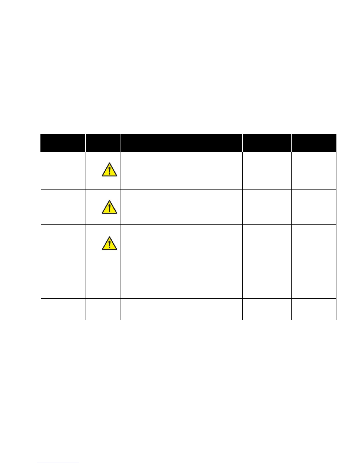
C a u t i o n
Caution indicates:
Equipment may be damaged if procedures are not followed.
Improper settings may result in loss of containment.
Important information about unit operation.
How to Use This Manual
The Operation and Service Manual describes how to operate, configure, calibrate, maintain and
troubleshoot the Model RPM10 and RPM20 Room Monitors. The manual is divided into two
parts. Part one describes the unit and how to interface with the device. This section should be
read by users, facilities staff, and anyone who requires a basic understanding of how the device
operates.
Part two describes the technical aspects of the product which include operation, configuration,
calibration, maintenance and troubleshooting. Part two should be read by personnel
programming or maintaining the unit. TSI recommends thoroughly reading this manual
before changing any software items.
NOTE: This operation and service manual assumes that the monitor has been properly installed.
Refer to the Installation Instructions if there is any question as to whether the monitor has
been installed properly.
Safety Information
This section gives instructions to promote safe and proper handling of Model RPM10 and RPM20
Room Monitors.
There are no user-serviceable parts inside the instrument. Opening the instrument case will void
the warranty. Refer all service of the unit to a qualified technician.
Description of Caution Symbol
Access Code / Passcode
Model RPM10 and RPM20 Room Monitors have access codes to limit unauthorized access to
the room mode or complete menu system. The access codes can be turned on or off through the
Passcode menu item. When the units ship from TSI, they are configured with the access code
off. Refer to Appendix D, Passcode, for instructions on entering the access code.
1

(This page intentionally left blank)
2

Part One
User Basics
This section is designed to provide a brief but thorough overview of the product installed. These
few pages explain the purpose (The Instrument) and the operation (Useful user information,
Operator panel, Alarms) of the product. Technical product information is available in Part Two of
the manual.
The Instrument
The Model RPM10 and RPM20 Monitors are designed to measure and report room pressure
differential in health-care facilities and other critical environments. They also can measure other
parameters, such as supply flow, exhaust flow, relative humidity, and room temperature.
Useful User Information
The display of the monitor is colored gray, green, or red. Green indicates the room pressure
differential and other configured measurements are adequate. The display turns red to indicate
alarm status when the room pressure differential or another configured measurement has risen
above or dropped below a safe level. The display provides additional information depending on
the configuration of the unit. Gray indicates that the room is in no isolation mode and will not
alarm if room pressure differential is not maintained.
Operator Panel
The Model RPM10 and RPM20 Room Monitors are easy to use. Normal vs. alarm condition and
room modes are always shown on the display. In addition, the displayed can be configured to
show the room pressure differential or all measurements. Specific details about the front panel
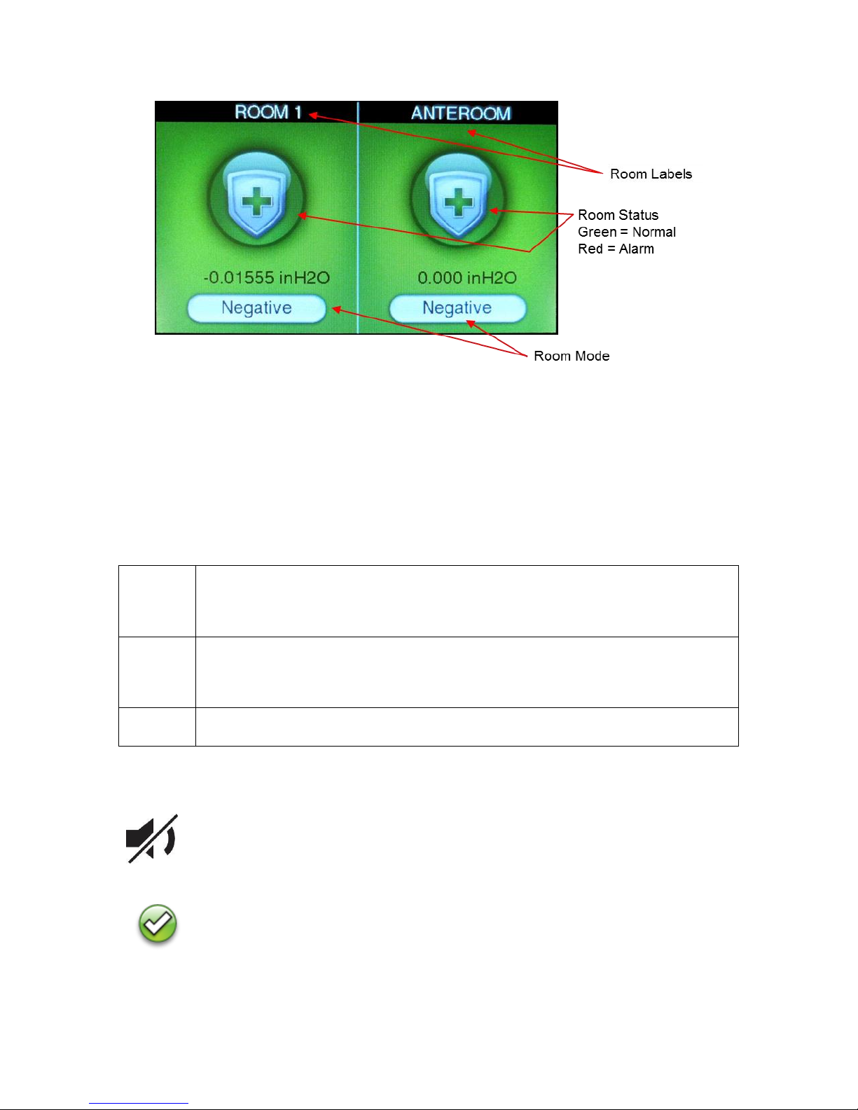
display and controls are described on the following pages. The front panel, shown in Figure 1 and
Figure 2 identifies the important features on the display:
Figure 1. Single Room Screen
User Basics 3
Green
The screen icon is colored green (NORMAL) when the room pressure and/or other
configured measurements are adequate. This light indicates the room is operating
safely. If a set point cannot be maintained or an alarm limit has been reached, the
green light turns off and the red alarm light turns on.
Red
The room icon is colored red (ALARM) when the room pressure and/or other
configured measurements are not within alarm limits. This light indicates the room is
not operating safely. The display screen will also indicate the type of alarm or an
emergency message.
Gray
The room icon is colored gray to indicate No Isolation mode. In No Isolation mode
the Model RPM10 and RPM20 will not alarm.
MUTE key
The MUTE key silences an audible alarm. The alarm remains silent until the
MUTE TIME value has been reached or the unit returns to control set point.
ACKNOWLEDGE key
The ACKNOWLEDGE key clears alarms when the Model RPM10 and RPM20
have been set latched alarms under the ALARM RESET item.
Figure 2. Two Room Screen
Display Screen
The LCD display is highly configurable and can display various critical information including
pressure differential, flow rate, alarm status, menu options, and error messages. In addition, the
LCD display is used for programming the unit. When programming the unit, the display will show
menus, menu items, and current value of the menu item, depending on the specific programming
function being performed.
Room Indicator Colors
Operator Keys
The following keys appear on the display of the Model RPM10 and RPM20 room monitor:
4 Part One

USB Port
There is a USB port on the case. This USB port can be used with TSI’s Configuration Software.
Figure 3. USB Port Location
Alarms
The Model RPM10 and RPM20 monitors have visual (red light) and audible alarms to inform you
of changing room conditions. The alarm levels (set points) are determined by facilities staff, which
could be Engineering, Industrial Hygiene, or a facilities group depending on how the safety staff
is organized.
The audible and visual alarms will activate whenever the field configured alarm level is reached.
The alarms will activate if the room pressure differential is low or inadequate, high or too great, or
when the airflow is too low or too high (need optional flow device installed). When the room is
operating safely, no alarms will sound.
Example: The low alarm is preset to activate when the room pressure differential falls below -
0.01 in H2O (closer to neutral). When the room pressure drops to -0.005 in H2O, for
example, the audible and visual alarms activate. The alarms turn off (when set to
unlatched) when the unit returns to the safe range, which is defined as 0.001 in H2O
greater than alarm set point (-0.01 in H2O).
Visual Alarm
The display of the monitor turns red to indicate an alarm condition. The icon turns continuously
red for all alarm conditions.
Audible Alarms
The audible alarm is continuously on in all low and high alarm conditions. The audible alarm can
be silenced by pressing the key.
If the audible alarm has been muted, the alarm is silenced for a configurable period of time (see
menu item MUTE TIME) or the measurement returns to the safe range. The safe range is
0.001 in H2O (50 cfm) above the low alarm set point and 0.001 in H2O (50 cfm) below the high
alarm set point.
User Basics 5

The audible and visual alarms can be programmed to either automatically turn off when the unit
returns to the safe range or to stay in alarm until the key is pressed (See menu item
ALARM RESET).
Alarm Relays
The PresSura monitors feature 2 alarm relays. The alarm relays can be field configured to either
open or close to indicate an alarm condition, although they will close on loss of power.
Relay 1 functions as the low alarm relay, and will activate after the alarm delay for low pressure,
low flow, low temperature and low RH alarms. Relay 1 will trigger without waiting for the alarm
delay to indicate a LOM alarm, or low pressure drop across a venturi valve, if a flow input is
configured for venturi valves.
Relay 2 is field-configurable to function as a high alarm relay or to indicate the room status. Refer
to the Relay 2 Out item in the Alarm Config menu for details on this operation.
Before Calling TSI
This manual should answer most questions and resolve most problems you may encounter. If
you need assistance or further explanation, contact your local TSI representative or TSI. TSI is
committed to providing high quality products backed by outstanding service.
Please have the following information available prior to contacting your authorized TSI
Manufacturer’s Representative or TSI:
- Model number of unit* RPM10 and RPM20
- Type of room pressure sensor (TSI Through-the-wall sensor or pressure transducer)
- Software revision level*
- Facility where unit is installed
* Can be determined by entering the Diagnostics menu.
Due to the different configurations of the Model RPM10 and RPM20 monitor available, the above
information is needed to accurately answer your questions.
For the name of your local TSI representative or to talk to TSI service personnel, please call TSI
at (800) 874-2811 (U.S. and Canada) or (001 651) 490-2811 (other countries).
Prior to shipping any components to TSI for service or repair, please utilize our convenient
Return Material Authorization (RMA) Form, which is available online at
https://secure.tsi.com/rma/intro.aspx.
6 Part One

The PresSura™ Room Pressure Monitor is
ready to use after being properly installed and
configured. The TSI through-the-wall sensor is
factory calibrated, as are most pressure
transducers. Figure 4 shows the Digital Interface
Module (DIM) which is programmed with a
default configuration that can be easily modified
to fit your application.
The technical section is separated into five parts
that cover all aspects of the unit. Each section is
written as independently as possible to minimize
flipping back and forth through the manual for
an answer.
Figure 4. PresSura Room Pressure Monitor
Part Two
Technical Section
The Software Programming section explains the programming keys on the DIM. In addition, the
programming sequence is described, which is the same regardless of the menu item being
changed. At the end of this section is an example of how to program the DIM.
The Menu and Menu Items section lists all of the software items available to program and
change. The items are grouped by menu which means all set points are in one menu, control
signal items in another, etc. The menu items and all related information is provided including;
programming name, description of menu item, range of programmable values, and how the unit
shipped from the factory (default value).
The Calibration section describes the required procedure to calibrate the controller. This section
explains how to compare the controller’s reading to a portable thermal anemometer and then
adjust the span to establish an accurate calibration. This section also describes how to zero a
TSI flow station transducer (if installed).
The Maintenance and Repair Parts section covers all routine maintenance of equipment, along
with a list of repair parts.
The Troubleshooting section is split into two areas: mechanical operation of the unit and system
performance. Many external variables will affect how the unit functions so it is critical to first
determine if the system is having mechanical problems—i.e., no display on unit, alarms do not
function, , etc. If no mechanical problems exist, look for performance problems (i.e., does not
seem to read correctly, display fluctuates, etc.). The first step is to determine that the system is
mechanically operating correctly, followed by modifying the configuration to eliminate the
performance problems.
Technical Section 7
Software Programming
Programming the PresSura Model RPM10/RPM20 monitor is quick and easy if the proper
keystroke procedure is followed. The programming keys are defined first, followed by the
required keystroke procedure. At the end of this section is a programming example.
NOTE: It is important to note that the unit is always operating when programming. When a menu
item value is changed, the new value takes effect immediately after saving the change,
not when the unit returns to normal operating mode.
This section covers programming the instrument through the keypad and display. If
programming through network communications (see Appendix B), use the host
computer’s procedure. The changes take place immediately upon saving data in the
instrument.
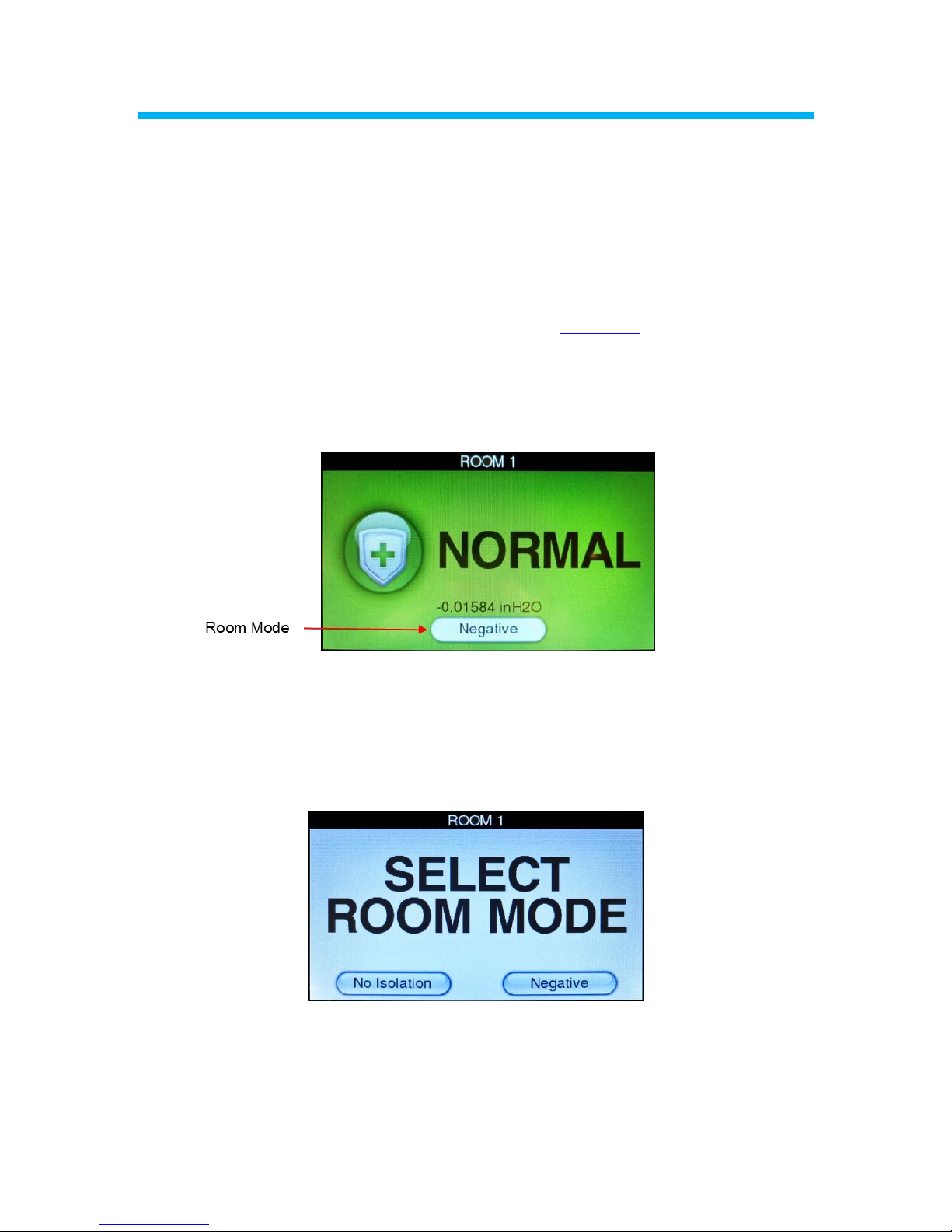
Changing Room Mode
1. Press the Room Mode button for the room on the touchscreen.
Figure 5. Main Running Screen
2. Select the desired room mode by pressing on the desired room mode button at the bottom of
the screen.
NOTE: If a room mode is not selected, the PresSura monitor will return to the main running
screen after a short delay,
Figure 6. Room Mode Selection Screen
8 Part Two
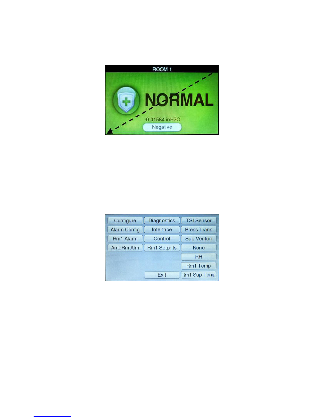
Entering Menus
Swipe across the display, from the top right corner to the bottom left corner, to access the
menu system.
Figure 7. Swipe to access menu system
Menus and Menu Items
After accessing a menu, the screen will change to show the items associated with that menu.
Refer to the Menu and Menu Items section for a list of the menus and their associated items.
Entering Data
After entering a menu item, the Model RPM10/RPM20 monitor display will change to select items.
Some items have pre-defined choices selected through a drop-down menu; others allow numeric
setpoints. Not all menus will be available on all models.
Figure 8. Menu System
Technical Section 9
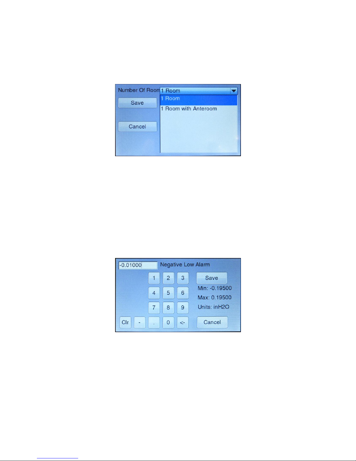
Drop-Down Selection
It is easy to view available choices and make a selection from drop-down items. Touch the item
displayed in the drop-down box to view all available options. Then, touch the item desired. Touch
the Save button to save your selection and exit the item or touch the Cancel button to exit the
item without saving.
Figure 9. Using a Drop-Down Selection
Numeric Setpoints
It is easy to enter new numeric setpoints on the PresSura Model RPM10/RPM20 monitor. On a
numeric setpoint screen, the current setpoint is displayed in a box at the top left of the screen.
Use the numeric keypad to enter a new setpoint.
The value entered must be between the min and max listed on-screen.
The measurement units are displayed as units. The <- button deletes the last digit.
The Clr button clears the entire setpoint.
The Save button saves your selection and exits the item.
The Cancel button exits the item without saving changes.
10 Part Two
Figure 10. Entering Numeric Setpoints
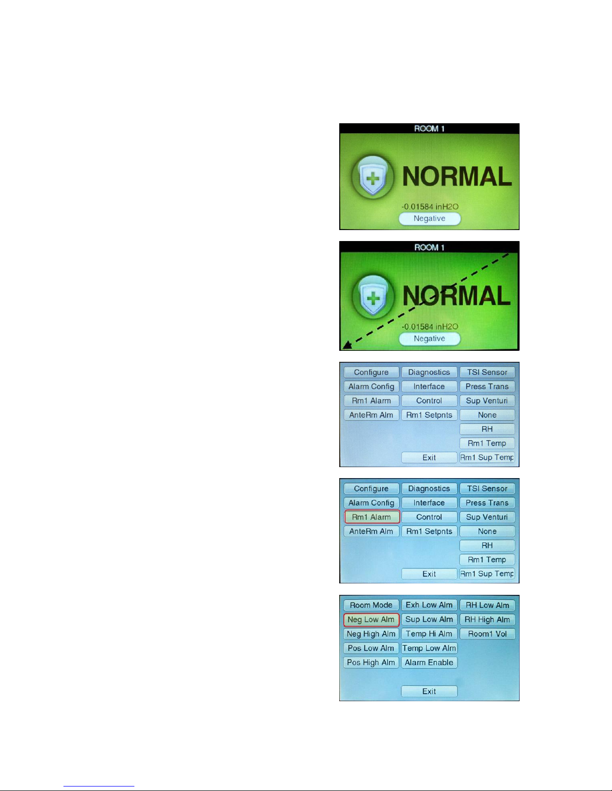
Unit is in normal operation.
Swipe from the top right corner to the
bottom left corner to access the menu
system.
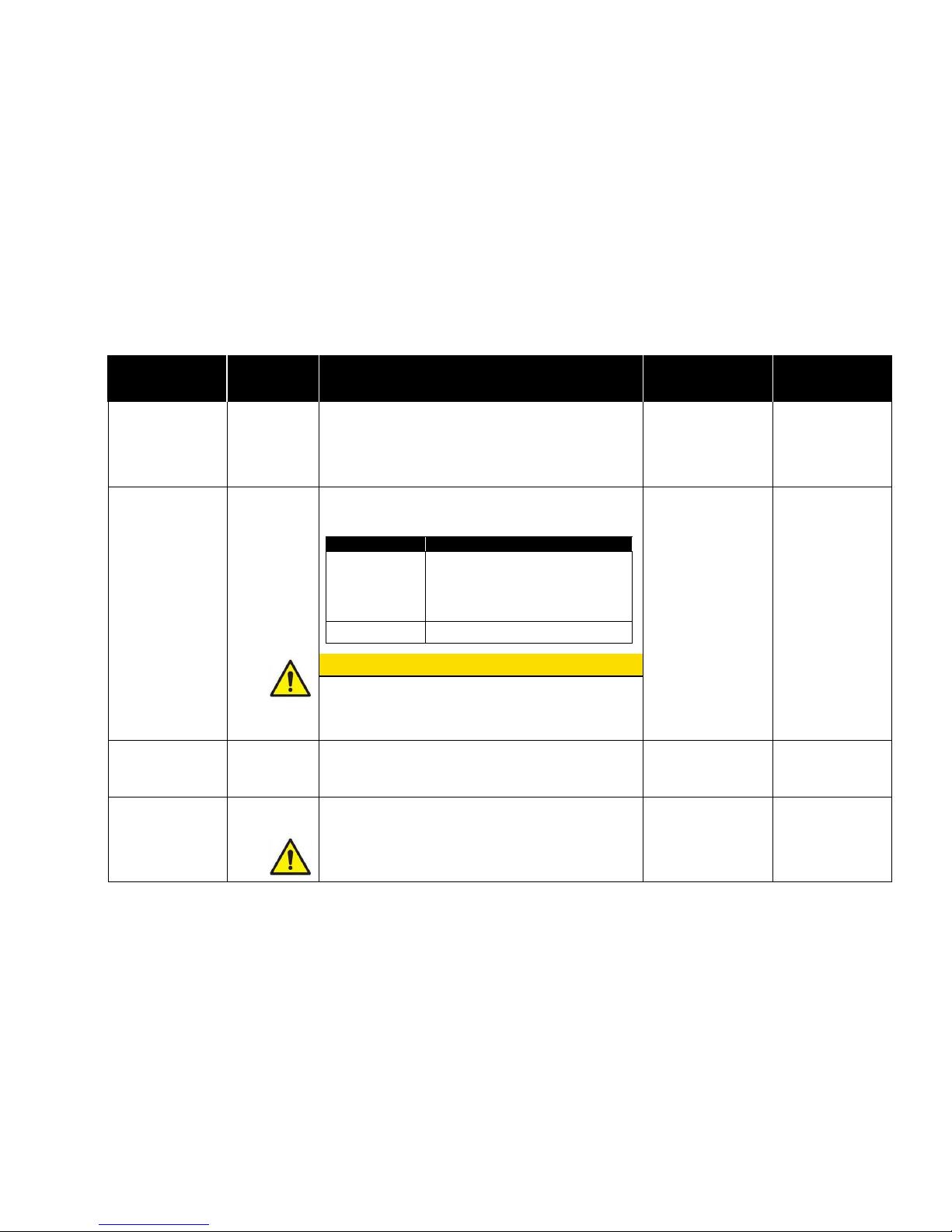
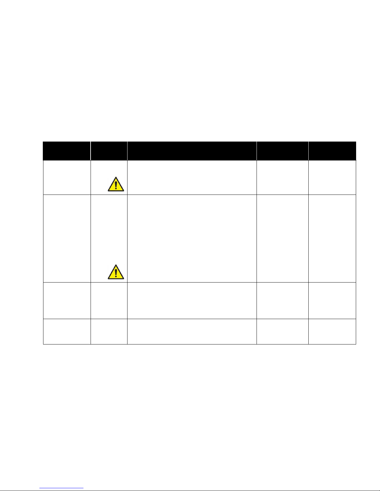
The menu screen is displayed.
Select the Rm1 Alarm menu.
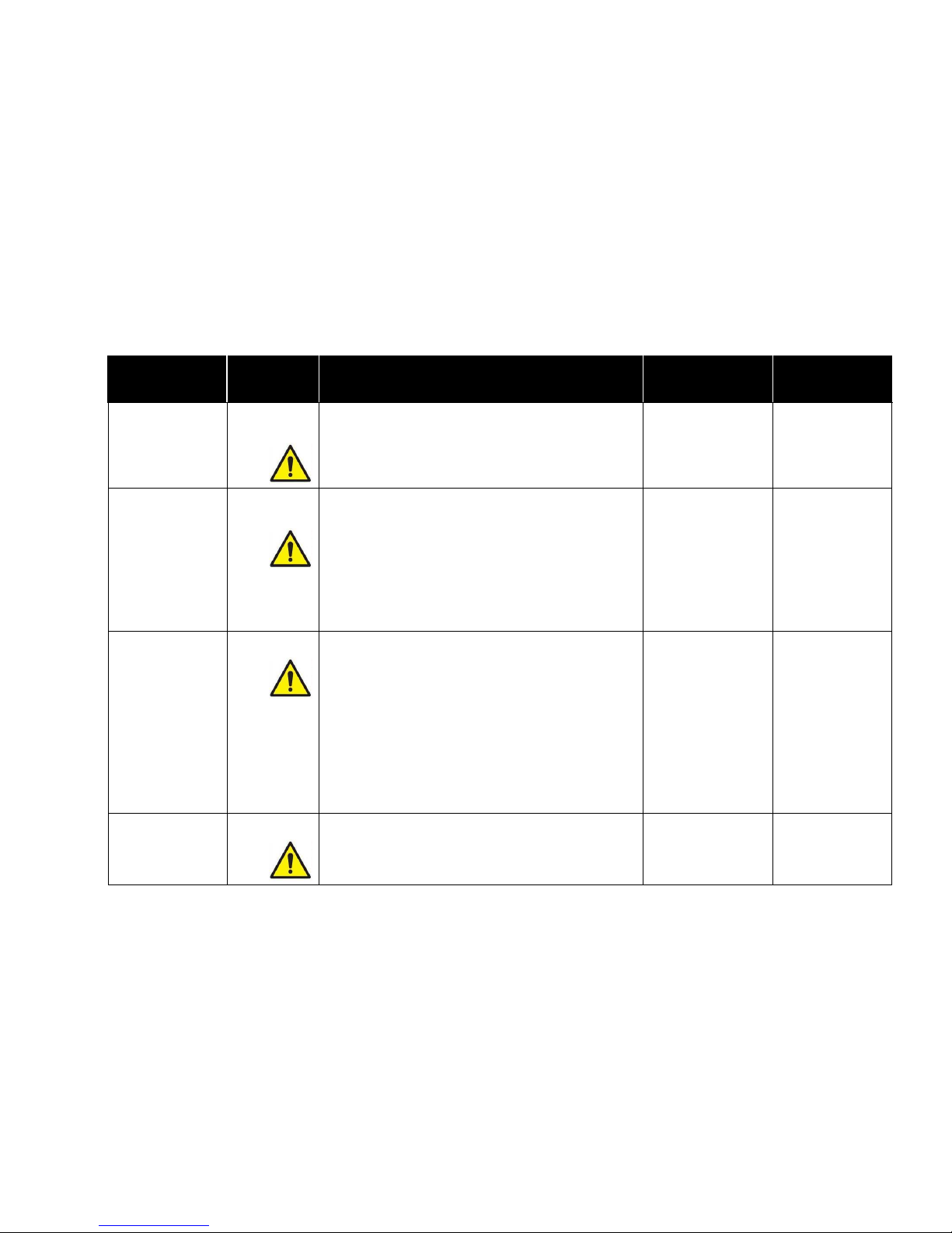
Select the Neg Low Alm item.
Programming Example
The following example demonstrates the keystroke sequence. In this example the negative low
alarm set point for Room 1 will be changed from -0.01000 in H2O to -0.01300 in H2O.
Technical Section 11

Enter the new setpoint of -
0.01300 in H2O. Save the new setting.
Touch the Exit button in the Rm1 Alarm menu and again in the main menu to
return to the main running screen.
Menu and Menu Items
The PresSura Model RPM10 and RPM20 monitors are very versatile devices which can be
configured to meet your specific application. This section lists all of the menu items available to
program and change (except diagnostics menu). Changing items is accomplished by using the
touchscreen or through communications with the Building Automation System. If you are
unfamiliar with the keystroke procedure please see Software Programming section for a detailed
explanation. This section provides the following information:
Complete list of menus and all menu items.
Gives the menu or programming name.
Defines each menu item’s function; what it does, how it does it, etc.
Gives the range of values that can be programmed.
Gives default item value (how it shipped from factory).
The menus covered in this section are divided into groups of related items to ease programming.
As an example all set points are in one menu, alarm information in another, etc. The manual
follows the menus as programmed in the controller. The menu items are always grouped by
menu and then listed in menu item order, not alphabetical order.
Figure 11 and Figure 12 show the PresSura Model RPM10 and RPM20 monitor menu items.
12 Part Two

Configure
Rm1 Alarm
Diagnostics
Alarm Config
# of Rooms
Press Modes
Rm1 Label
Display Meas
Display Avg
Units
Passcode
Num Format
Input 1
Input 2
Input 3
Input 4
Input 5
Input 6
Input 7
Room Mode
Neg Low Alm
Neg Hi Alm
Pos Low Alm
Pos Hi Alm
Exh Low Alm
Sup Low Alm
Alarm Enable
ACH Duct
Room 1 Vol
View Inputs
View Outputs
Relay Outputs
Analog Outpt
Touch Cal
Reset
Alarm Reset
Audible Alm
Alarm Delay
Mute Time
Door Delay
Relay 2 Out
Relay 1 Dir
Relay 2 Dir
Interface
Input 1 Configure
Input 2 Configure
Input 3 Configure
Comm Type
Address
MAC ID
Baud Rate
Nurse Address
AO1 Sig Type
AO2 Sig Type
AO2 Sig Rnge
AO2 Out Type
AO3 Sig Type
See menu for items.
See menu for items.
See menu for items.
Input 4 Configure
Input 5 Configure
Input 6 Configure
Input 7 Configure
See menu for items.
See menu for items.
See menu for items.
See menu for items.
Figure 11. Menu Items – Model RPM10 Monitor
Technical Section 13

Configure
Rm1 Alarm
AnteRm Alarm
Rm2 Alarm
# of Rooms
Rm1 Label
AnteRm Label
Rm2 Label
Display Meas
Display Avg
Units
Passcode
Num Format
Input 1
Input 2
Input 3
Input 4
Input 5
Input 6
Input 7
Room Mode
Neg Low Alm
Neg Hi Alm
Pos Low Alm
Pos Hi Alm
Exh Low Alm
Sup Low Alm
Temp Low Alm
Temp Hi Alm
ACH Duct
Room1 Vol
RH Low Alm
RH High Alm
Alarm Enable
Room Mode
Neg Low Alm
Neg Hi Alm
Pos Low Alm
Pos Hi Alm
Alarm Enable
Room Mode
Neg Low Alm
Neg Hi Alm
Pos Low Alm
Pos Hi Alm
Alarm Enable
Alarm Config
Diagnostics
Interface
Input 1 Configure
Alarm Reset
Audible Alm
Alarm Delay
Mute Time
Door Delay
Relay 2 Out
Relay 1 Dir
Relay 2 Dir
View Inputs
View Outputs
Relay Outputs
Analog Outpt
Touch Cal
Reset
Comm Type
LON
Address
MAC ID
Baud Rate
Nurse Address
AO1 Sig Type
AO2 Sig Type
AO2 Sig Rnge
AO2 Out Type
AO3 Sig Type
AO3 Sig Rnge
AO3 Out Type
See menu for items.
Input 2 Configure
Input 3 Configure
Input 4 Configure
Input 5 Configure
See menu for items.
See menu for items.
See menu for items.
See menu for items.
Input6 Configure
Input 7 Configure
See menu for items.
See menu for items.
Figure 12. Menu Items – Model RPM20 Monitor
14 Part Two
Technical Section 15
Configure Menu
MENU ITEM
Monitor/
Controller
SOFTWARE
NAME
ITEM DESCRIPTION
ITEM RANGE
DEFAULT VALUE
Number of Rooms
Monitored
RPM10 and
RPM20
# of Rooms
The # of Rooms item selects the number of rooms the
Model RPM10 and RPM20 monitor will monitor and
control.
RPM10: 1 Room
RPM20: 1 Room,
1 Room with
Anteroom, 2 Rooms
with Anteroom
1 Room
Number of
Pressure Mode
Selections
RPM10 and
RPM20
Press Modes
The Press Modes item determines the room modes
available for selection when the user presses the Room
Mode button on the main running screen.
Press Mode
Room Mode Selections on Screen
2 Buttons
Positive / No Isolation
Or
Negative / No Isolation
(based on Room Mode item in
respective Alarm menu)
3 Buttons
Negative / No Isolation / Positive
2 Buttons, 3 Buttons
2 Buttons
WARNING
Codes and Standards in the US and many other areas of
the world do not allow a room to be switched from Positive
to Negative Isolation. Consult local authorities before
setting Press Modes to 3 Buttons.
Label for Room 1
RPM10 and
RPM20
Rm1 Label
The Rm1 Label item allows the user to set the room
number or other designator for room 1.
13 characters of text
ROOM 1
Label for Room 2
Rm2 Label
The Rm2 Label item allows the user to set the room
number or other designator for room 2.
13 characters of text
ROOM 2
RPM20
NOTE: Rm2 Label is only active if the # of Rooms item
is set to 2 Rooms with Anteroom.
16 Part Two
Configure Menu
MENU ITEM
Monitor/
Controller
SOFTWARE
NAME
ITEM DESCRIPTION
ITEM RANGE
DEFAULT VALUE
Label for Anteroom
AnteRm Label
The AnteRm Label item allows the user to set the room
number or other designator for the anteroom.
13 characters of text
ANTEROOM
RPM20
NOTE: AnteRm Label is only active if the # of Rooms
item is set to 1 Room with Anteroom or
2 Rooms with Anteroom.
Measurements
Displayed
RPM10 and
RPM20
Display Meas
The Display Meas item selects which measurements will
be presented on the display during normal operating
mode. Use the Units item to choose the units of measure:
ROOM STATUS displays the room mode as negative,
positive or no isolation.
ROOM PRESSURE displays the room mode and the
current measurement of room pressure differential.
ALL displays the room mode and all currently connected
measurements. Only functions when # of Rooms is set to
1 Room
Room Status,
Room Pressure, All
Room Status
NOTE: Measurements will still enable alarms if not on the
display. The measurement will not appear on the
display
Display Average
RPM10 and
RPM20
Display Avg
The Display Avg item selects the display’s running
average period. The display-averaging period is the length
of time the face velocity has been averaged before being
displayed. The Display Avg item value may be set
between 0.5 and 40 seconds. The higher the averaging
value, the more stable the display.
1, 2, 3, 5, 10, 20, or
40 seconds
20 seconds
Display Units
RPM10 and
RPM20
Units
The Units item selects the unit of measure that the
monitor displays all values (except calibration span).
These units display for all menu items setpoints, alarms,
flows, etc.
in H2O, cfm, F
Pa, l/s, C
Pa, cmh, C
in H2O, cfm
Technical Section 17
Configure Menu
MENU ITEM
Monitor/
Controller
SOFTWARE
NAME
ITEM DESCRIPTION
ITEM RANGE
DEFAULT VALUE
Configure INPUT1
RPM10 and
RPM20
Input 1
The Input 1 item selects the desired input type for Input1,
the room pressure sensor for Room 1
TSI Sensor, Pressure
Transducer
TSI Sensor
Go to the Input 1 menu to adjust parameters such as
sensor range associated with Input1.
Configure INPUT2
RPM20
Input 2
The Input 2 item selects the desired input type for Input2,
the room pressure sensor for the AnteRm.
TSI Sensor, Pressure
Transducer, None
None
Go to the Input2 menu to adjust parameters such as
sensor range associated with Input2.
The Input 2 item is only active if the # of Rooms item is
set to 1 ROOM WITH ANTEROOM.
The Input 2 item is not functional on the Model RPM10
Monitor. It is only active on the Model RPM20 Monitor.
Configure INPUT3
RPM10 and
RPM20
Input 3
The Input 3 item selects the desired input type for Input3.
RPM10: Supply
Pressure Flow
Supply Linear Flow,
Supply Venturi Flow,
Supply Switch, None
RPM20: Supply
Pressure Flow
Supply Linear Flow,
Supply Venturi Flow,
Supply Switch
TSI Sensor, Pressure
Transducer, None
None
Go to the Input 3 menu to adjust parameters such as
sensor range associated with Input3.
The Model RPM10 Monitor cannot be set to TSI Sensor or
Pressure Transducer.
Input 3 can only be set to TSI Sensor or Pressure
Transduce if the # of Rooms item is set to 2 Rooms with
Anteroom.
Configure INPUT4
RPM10 and
RPM20
Input 4
The Input 4 item selects the desired input type for Input4.
None,
Room1 Door Switch,
Room 1 Occupancy
Sensor
None
Go to the Input 4 menu to adjust parameters such as
sensor range associated with Input4.
18 Part Two
Configure Menu
MENU ITEM
Monitor/
Controller
SOFTWARE
NAME
ITEM DESCRIPTION
ITEM RANGE
DEFAULT VALUE
Configure INPUT5
RPM10 and
RPM20
Input 5
The Input 5 item selects the desired input type for Input5.
RPM10: None,
Room1 Key Switch
RPM20: None,
Room1 Key Switch,
Relative Humidity
Sensor
None
Go to the Input 5 menu to adjust parameters such as
sensor range associated with Input5.
The Model RPM10 Monitor cannot be set to Relative
Humidity Sensor.
Configure INPUT6
RPM20
Input 6
The Input 6 item selects the desired input type for Input6.
None, Room1 Temp
Sensor, Room 2
Occupancy Sensor,
Room 2 Door Switch
None
Go to the Input 6 menu to adjust parameters such as
sensor range associated with Input6.
The Input 6 item is not functional on the Model RPM10
Monitor. It is only active on the Model RPM20 Monitor.
Configure INPUT7
RPM10 and
RPM20
Input 7
The Input 7 item selects the desired input type for Input7.
RPM10: Exhaust
Pressure Flow,
Exhaust Linear Flow,
Exhaust Venturi
Flow, Exhaust
Switch, None
RPM20: Exhaust
Pressure Flow,
Exhaust Linear Flow,
Exhaust Venturi
Flow, Exhaust
Switch, Room 2
Key Switch, None
None
Go to the Input 7 menu to adjust parameters such as
sensor range associated with Input7.
Input 7 can only be set to Room 2 Key Switch if the # of
Rooms item is set to 2 Rooms With Anteroom.
The Model RPM10 Monitor cannot be set to Room 2
Key Switch.
Number Format
RPM10 and
RPM20
Num Format
The Num Format menu item selects the way that
numbers are displayed.
Period
Comma
Period

Technical Section 19
Configure Menu
MENU ITEM
Monitor/
Controller
SOFTWARE
NAME
ITEM DESCRIPTION
ITEM RANGE
DEFAULT VALUE
Enable Access
Codes
RPM10 and
RPM20
Passcode
The Passcode item selects whether an access code
(pass code) is required to enter the menu items. The
Passcode item prevents unauthorized access to a menu.
If the Passcode item is:
OFF no code is required to enter the room
mode or menu screens.
ROOM MODE access code is required to enter the
room mode screens but not the menu
screens
MENUS access code is required to enter the
menu screens but not the room mode
screens
ALL access code is required to enter the
room mode and menu screens.
Off
Room Mode
Menus
All
Menus
Rm1 Alarm Menu
MENU ITEM
SOFTWARE
NAME
ITEM DESCRIPTION
ITEM RANGE
DEFAULT VALUE
Mode of Room 1
RPM10 and
RPM20
Room Mode
The Room Mode item selects the room pressure
direction. This item enables all related alarms, for
pressure direction selected.
NOTE: No Isolation Room Mode can be selected from the
main running screen.
Positive
Negative
Negative
Room 1 Alarm
Enable
RPM10 and
RPM20
Alarm Enable
The Alarm Enable item enables the low and high alarm
functions. When this item is entered, the monitor will show
buttons for Low Alarms and High Alarms. Press the button
to toggle between enabling and disabling the alarms.
NOTE: The Alarm Enable item enables or disables
pressure, flow, temperature and humidity alarms.
Enabled
Disabled
Low Alarms
Enabled
High Alarms
Disabled

20 Part Two
Rm1 Alarm Menu
MENU ITEM
SOFTWARE
NAME
ITEM DESCRIPTION
ITEM RANGE
DEFAULT VALUE
Room 1 Negative
Low Alarm
RPM10 and
RPM20
Neg Low Alm
The Neg Low Alm item sets the negative low pressure
alarm setpoint. A low alarm condition is defined as when
the magnitude of the room pressure falls below the Neg
Low Alm setpoint.
This item is active when the TSI key switch is in negative
room pressure position or when NEGATIVE is selected in
ROOM MODE item. However, it is always accessible
through the menu system.
-0.19500 in H2O to
+0.19500 in H2O
Note: Neg Low Alm
cannot be set
more negative
than the Neg Hi
Alm
-0.01000 in H2O
Room 1 Negative
High Alarm
RPM10 and
RPM20
Neg Hi Alm
The Neg Hi Alm item sets the negative high pressure
alarm setpoint. A high alarm condition is defined as when
the room is more negative than the Neg Hi Alm setpoint.
This item is active when the TSI key switch is in negative
room pressure position or when NEGATIVE is selected in
ROOM MODE item. However, it is always accessible
through the menu system.
-0.19500 in H2O to
+0.19500 in H2O
Note: Neg Hi Alm
cannot be set
less negative
than the Neg
Lo Alm
-0.10000 in H2O
Room 1 Positive
Low Alarm
RPM10 and
RPM20
Pos Low Alm
The Pos Low Alm item sets the positive low pressure
alarm setpoint. A low alarm condition is defined as when
the room is less positive than the Pos Low Alm setpoint.
This item is active when the TSI key switch is in positive
room pressure position or when POSITIVE is selected in
ROOM MODE item. However, it is always accessible
through the menu system.
-0.19500 in H2O to
+0.19500 in H2O
Note: Pos Low Alm
cannot be set
more positive
than the Pos Hi
Alm
+0.01000 in H2O
Room 1 Positive
High Alarm
RPM10 and
RPM20
Pos Hi Alm
The Pos Hi Alm item sets the positive high pressure
alarm setpoint. A high alarm condition is defined as when
the magnitude of the room pressure rises above the Pos
Hi Alm setpoint.
This item is active when the TSI key switch is in positive
room pressure position or when POSITIVE is selected in
ROOM MODE item. However, it is always accessible
through the menu system.
-0.19500 in H2O to
+0.19500 in H2O
Note: Pos Hi Alm
cannot be set
less positive
than the Pos
Lo Alm
+0.10000 in H2O

Technical Section 21
Rm1 Alarm Menu
MENU ITEM
SOFTWARE
NAME
ITEM DESCRIPTION
ITEM RANGE
DEFAULT VALUE
Room 1 Low
Exhaust Flow
Alarm
RPM10 and
RPM20
Exh Low Alm
The Exh Low Alm item sets the minimum exhaust flow
alarm setpoint. A minimum flow alarm is defined as when
the exhaust flow is less than the Exh Low Alm setpoint.
0 to 30,000 cfm
0 cfm
Room 1 Low
Supply Flow Alarm
RPM10 and
RPM20
Sup Low Alm
The Sup Low Alm item sets the minimum supply flow
alarm setpoint. A minimum flow alarm is defined as when
the supply flow is less than the Sup Low Alm setpoint.
0 to 30,000 cfm
0 cfm
Room 1 Low Room
Temperature Alarm
RPM20
Temp Low
Alm
The Temp Low Alm item sets the minimum room
temperature alarm setpoint.
50 to 100°F
Note: Temp Low Alm
cannot be set
greater than the
Temp Hi Alm
50°F
High Room
Temperature Alarm
RPM20
Temp Hi Alm
The Temp Hi Alm item sets the maximum room
temperature alarm setpoint.
50 to 100°F
Note: Temp Hi Alm
cannot be set
less than the
Temp Low Alm
100°F
Low Relative
Humidity Alarm
RPM20
RH Low Alm
The RH Low Alm item sets the minimum relative humidity
alarm setpoint.
0 to 100%
Note: RH Low Alm
cannot be set
greater than the
RH Hi Alm
0%
High Relative
Humidity Alarm
RPM20
RH Hi Alm
The RH Hi Alm item sets the maximum relative humidity
alarm setpoint.
0 to 100%
Note: RH Hi Alm
cannot be set
less than the
RH Low Alm
100%

22 Part Two
Rm1 Alarm Menu
MENU ITEM
SOFTWARE
NAME
ITEM DESCRIPTION
ITEM RANGE
DEFAULT VALUE
Duct for Air
Changes per Hour
Calculation
RPM10 and
RPM20
ACH Duct
The ACH Duct item sets the duct to be used for ACH
calculations:
SUPPLY is normally used for positive rooms
EXHAUST is normally used for negative rooms
OFF is used if the ACH calculation is not
desired
OFF
SUPPLY
EXHAUST
OFF
Room Volume
RPM10 and
RPM20
Room1 Vol
The Room1 Vol item sets the room volume for the ACH
calculation.
0 to 20,000 ft3
0 ft3
AnteRm Alarm Menu
MENU ITEM
SOFTWARE
NAME
ITEM DESCRIPTION
ITEM RANGE
DEFAULT VALUE
Mode of Anteroom
RPM20
Room Mode
The Room Mode item selects the room pressure
direction. This item enables all related alarms, for
pressure direction selected. Selecting ROOM1 means that
the Room Mode will follow the Room Mode of Room 1.
NOTE: No Isolation Room Mode can be selected from the
main running screen.
Positive
Negative
Room1
Negative
Anteroom Alarm
Enable
RPM20
Alarm Enable
The Alarm Enable item enables the low and high alarm
functions. When this item is entered, the monitor will show
buttons for Low Alarms and High Alarms. Press the button
to toggle between enabling and disabling the alarms.
Enabled
Disabled
Low Alarms:
Enabled
High Alarms:
Disabled
Anteroom Negative
Low Alarm
RPM20
Neg Low Alm
The Neg Low Alm item sets the negative low pressure
alarm setpoint. A low alarm condition is defined as when
the magnitude of the room pressure falls below the Neg
Low Alm setpoint.
This item is active when the TSI key switch is in negative
room pressure position or when NEGATIVE is selected in
ROOM MODE item. However, it is always accessible
through the menu system.
-0.19500 in H2O to
+0.19500 in H2O
Note: Neg Low Alm
cannot be set
more negative
than the Neg Hi
Alm
-0.01000 in H2O
 Loading...