

Page 1
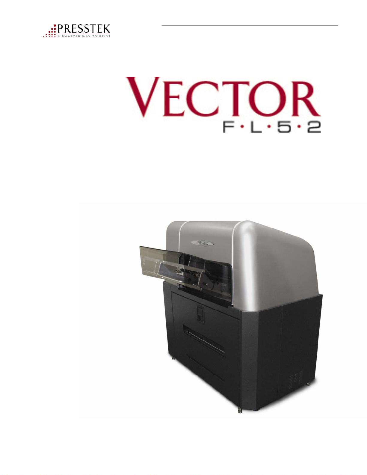
Autoloader
Operator Manual
ADD06731-F
Vector FL52AL Operator Manual
Page 2

Copyright © 2010 Presstek, Inc. All rights reserved.
Presstek, Inc. makes no representations or warranties with respect to the contents hereof and specifically
disclaims any implied warranties or merchantability or fitness for any particular purposes. Further, Presstek, Inc.
reserves the right to revise this publication and to make changes from time to time in the contents hereof without
obligation of Presstek, Inc. to notify any person organization of such revisions or changes.
Presstek, Inc. disclaims any responsibility or liability for personal injury, death or property damage
caused by or arising out of (i) failure of operators to observe all operating and safety instructions and
warnings contained herein or (ii) the improper use, abuse, neglect or unauthorized repair of the equipment
described herein, and the purchaser and any subsequent owner or lessee of such equipment shall defend,
indemnify and hold Presstek, Inc. harmless from and against all liability caused or arising out of such
nonobservance, improper use, abuse, neglect or unauthorized repair.
Presstek, Vector, Freedom Pro, SureFire, ThinDrum are trademarks of Presstek, Inc. All other
trade names are the property of their respective owners. Product information and specifications are subject
to change without notice.
Presstek, Inc.
55 Executive Drive
Hudson, NH 03051 USA
603-595-7000
www.presstek.com
April, 2010
ADD06731_E
Vector FL52AL Operator Manual
2
Page 3

Vector FL52AL
Operator Manual
Table of Contents
Chapter 1: Intro & Safety Information 5
Capitolo 1: Introducción e Información Sobre Seguridad 13
Chapitre 1: Présentation et informations sur la sécurité 21
Kapitel 1: Einleitung und Sicherheitsinformatimen 29
Chapter 2: Specifications 37
Chapter 3: Operation 41
Chapter 4: Operator Maintenance 64
Chapter 5: Troubleshooting 72
Chapter 6: Freedom Pro Plate 78
Appendix A: Supplies (Plates, Filters) 84
Customer Support: 1-800-422-3616
To order supplies, press 2
To place a service call, press 3
To order parts, press 4
For billing inquiries, press 5
For service contracts, press 6
For sales, press 7
3
Vector FL52AL Operator Manual
Page 4

This page intentionally left blank
Vector FL52AL Operator Manual
4
Page 5
Chapter 1
Introduction and Safety Information
Vector FL52AL Operator Manual
5
Page 6

Welcome
Congratulations on your purchase of the Vector FL52AL. This direct-to-metal
CTP device has combined leading edge thin drum technology with Surefire Laser
technology to provide you with this state of the art Platesetter.
About this Manual
This manual contains important information about installation, configuration,
and daily use of the Vector FL52AL, including working with Freedom Pro
metal plates.
Each chapter of this manual has a specific focus. The information contained in
these chapters is organized to provide ease of use and understanding leading
you to effective use of the Vector FL52AL.
Introduction and
Safety Information
Chapter 1: Introduction & Safety Information
This chapter describes relevant information about safe operation of the
Vector FL52AL, specifications about the equipment and also how to use this
manual effectively.
Chapter 2: Specifications
This chapter provides specifications for the Vector FL52AL platesetter and
Freedom Pro plate.
Chapter 3: Operation
This chapter explains procedures used in the daily operation of the Vector FL52AL.
Chapter 4: Operator Maintenance
This chapter describes routine maintenance tasks that must be performed on a
regular basis.
Chapter 5: Troubleshooting
This chapter explains warnings and error messages.
Vector FL52AL Operator Manual
6
Page 7

Chapter 6: Freedom Pro Plates
This chapter describes the Freedom Pro plate and includes a list of available sizes.
Appendix A:
Supplies and part numbers.
Conventions used in this manual
Certain conventions have been applied to this manual to aid in understanding the
information presented.
The following fonts and special symbols are used throughout the manual:
Text written in bold face represents a menu title, menu item or control item in a
dialog box.
Introduction and
Safety Information
Text written in bold typewriter face represents literal information,
which should be typed exactly as it appears in this manual
Text written in italics and appearing within a sentence, is important related
reference information.
Text preceded by an arrow is important information about the topic presented and
should be read carefully.
Assumptions
This manual assumes you have some familiarity with digital plate making as well as a
basic knowledge of the Microsoft Windows operating system.
Installing the VECTOR FL52AL
The hardware and software must be installed by an authorized service technician in
accordance with the installation instructions in the service manual and with national
and local regulations concerning electrical safety. In the event the Vector FL52AL
needs to be moved, please contact Customer Support at 1-800-422-3616.
Vector FL52AL Operator Manual
7
Page 8

Safety Warning
Introduction and
Safety Information
.
Standards Compliance
The Vector FL52AL is Class 4 rated electrical equipment (according to
EN 60825-1: 1994) and must be connected to a properly grounded
three (3) wire power supply in accordance with national and local
regulations. Failure to do so creates a potential danger of electrical shock.
The Vector FL52AL must be plugged into a dedicated, protected circuit .
The power cord used to connect the equipment to the facility power supply
must comply with national and local standards and must have a minimum
rated current capacity of 20 Amp. (N.A.)/16 Amp. (Europe).
Low Voltage Directive 73 / 23 / EEC to the following standards:
EN61010-1:2001 Safety Requirements for Electrical Equipment for Measurement,
Control and Laboratory Use – Part 1: General Requirements
CAN/CSA-C22.2 No. 61010-1-04
UL 61010-1: 2004
Electromagnetic Compatibility
FCC verification to part 15-B, Class A
EMC Directive 89/336/EEC to the following standards:
EN61326: 1997+A1: 1998+A2: 2001
EN61000-4 (1994-96)
Caution: Do not perform any adjustments or procedures other than those specified
in this manual.
8
Vector FL52AL Operator Manual
Page 9

Note to Users:
Introduction and
Safety Information
.
Protect yourself, others, and your equipment by observing all safety warnings
contained in this manual. Before attempting to operate the Vector FL52AL, be
certain that each operator has read this manual and is thoroughly familiar with
the operating instructions and safety warnings.
Read and heed all warning labels.
Do not modify the unit, remove guards, covers, etc. and/or attempt to defeat
any interlock switches. Under no circumstances attempt to operate the machine
without all safety covers, interlocks and other safety devices in their original,
factory-installed condition.
Presstek recommends that repair and servicing of your machine be performed only
by a qualified Presstek service representative or an authorized dealer/distributor.
Repair or servicing of this equipment by owners, operators, or unauthorized service
personnel is not advised due to the safety risks posed and the possibility of
voiding applicable warranty coverage.
Do not overfill the washer tank (see filling instructions). Be careful to avoid
spillage of water when filling and when sliding the washer unit in and out of
the machine. Do not use distilled water in the washer tank.
Under no circumstances are the door or cover interlocks to be defeated.
Vector FL52AL Operator Manual
9
Page 10
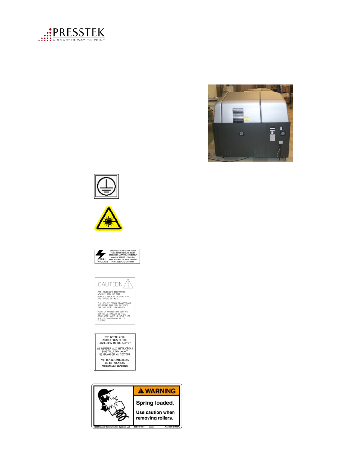
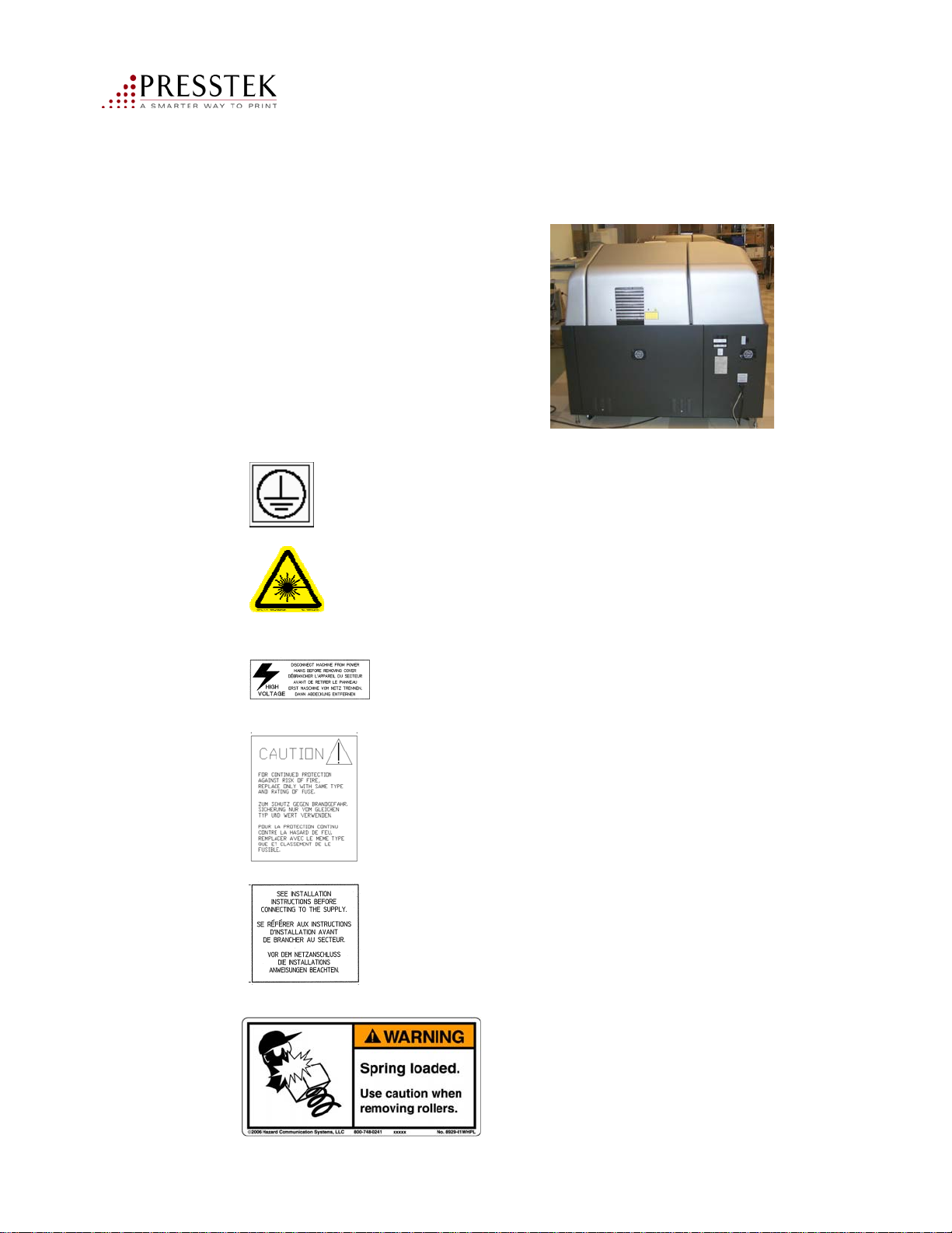
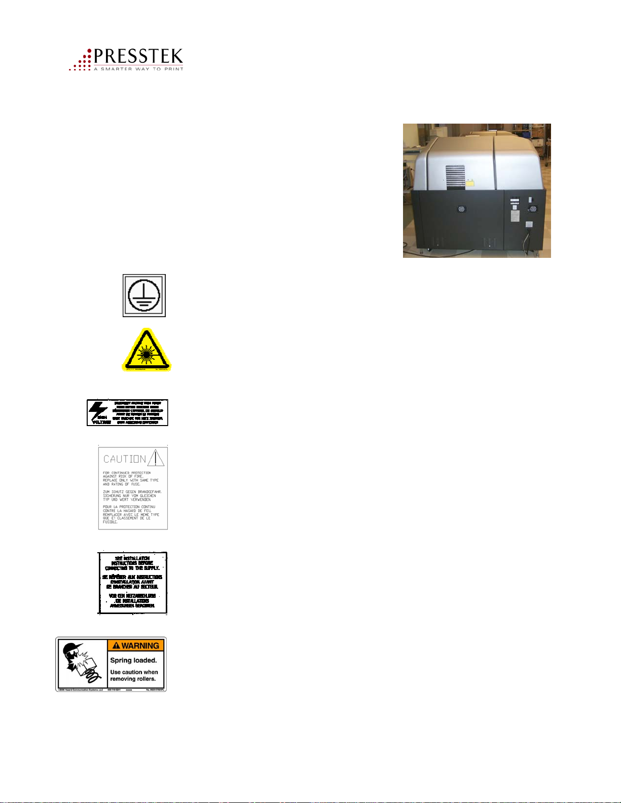
Vector FL52AL Electrical Warning Labels
.
There are several mandatory safety
and warning labels located on the
back of the Vector FL52AL:
Ground Symbol label: located inside the rear panel
near the ground stud.
Introduction and
Safety Information
Laser Safety Symbol label: located upper rear panel.
High Voltage Warning label: located rear panel, lower right.
Fuse Replacement Warning label located on rear panel of
unit near fuse indicator panel
Installation Instructions located near power cord outlet
on rear panel
This warning label is located
inside the washer unit for careful
removal and replacement of the
brush rollers and rubber transport
rollers.
10
Vector FL52AL Operator Manual
Page 11
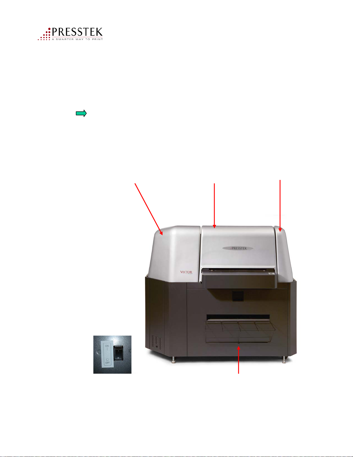
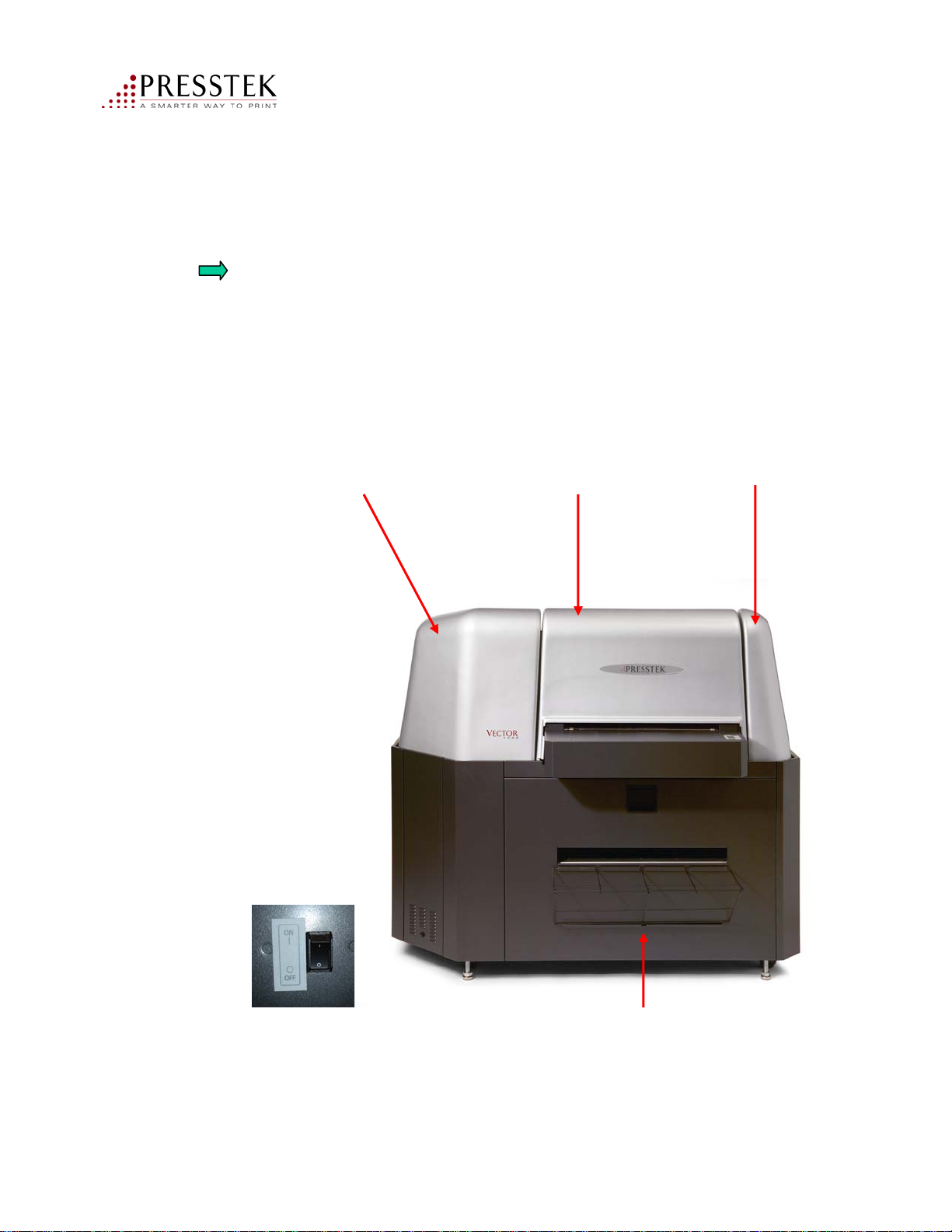
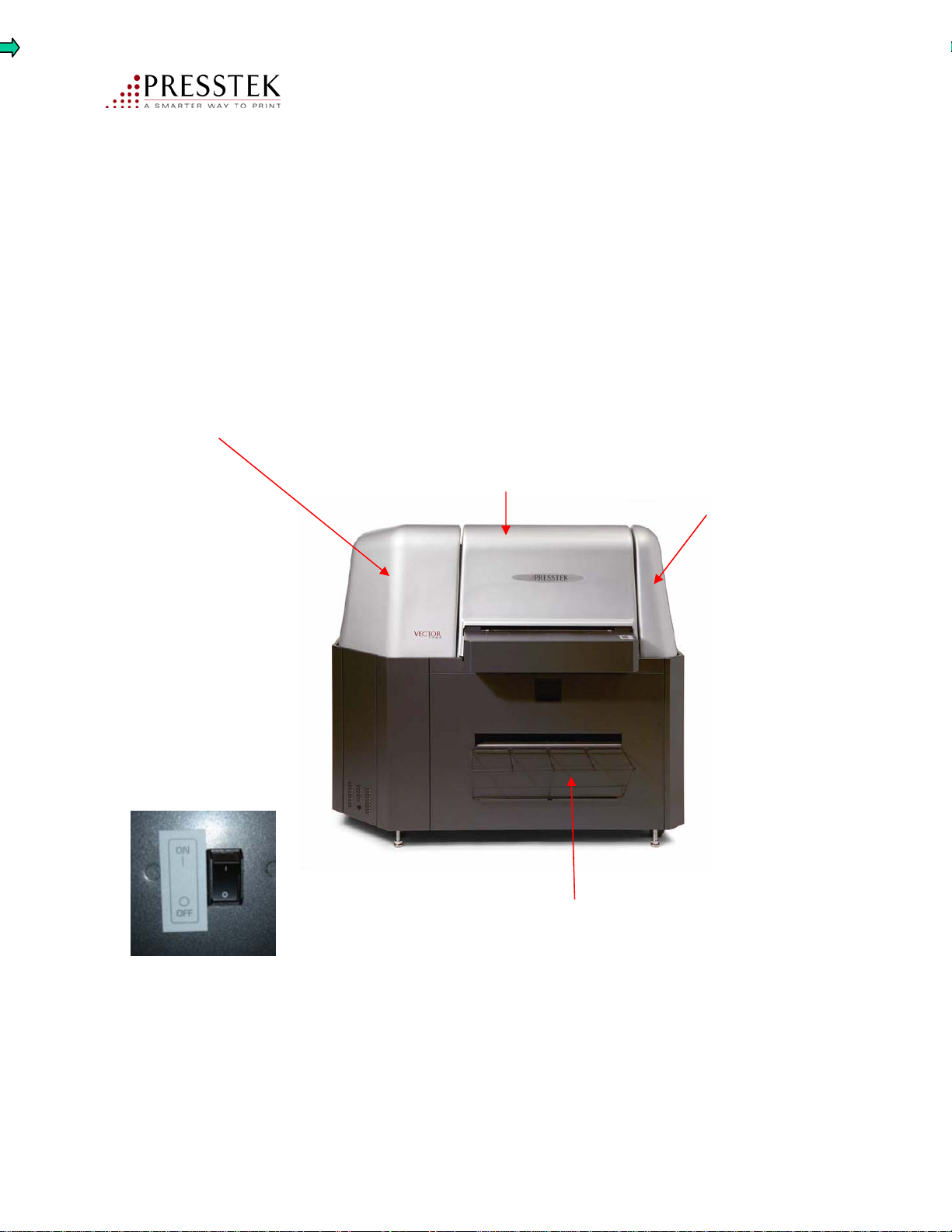
On/Off and Safety Interlock Switches
Safety Devices: Please refer to the illustration which identifies and describes
the function of the safety devices used on the Vector FL52AL.
Do not operate the unit without all covers, interlocks, and safety devices in their
original, factory-installed positions
Introduction and
Safety Information
LEFT SIDE COVER
INTERLOCK SWITCHES
One motor and one
Laser Interlock Switch
located under this cover.
CENTER-TOP COVER
(Mechanically secured by
baseframe with hardware
for access by authorized
Service Technician)
RIGHT SIDE COVER
INTERLOCK SWITCHES
One Motor and one
Laser Interlock Switch
located under this cover
ON/OFF Switch/Circuit
Breaker (15A)
located on the rear panel
Vector FL52AL Operator Manual
WASHER ACCESS DRAWER
INTERLOCK SWITCHES
Two interlock switches are deactivated
when drawer is opened. Heater, pump
and AC drive motors are disabled.
11
Page 12

This page intentionally left blank
Vector FL52AL Operator Manual
12
Page 13

Capítulo 1
Introducción e Información Sobre Seguridad
Derecho de Autor © 2010 Presstek, Inc Todos los derechos reservados.
Presstek, Inc no hace representaciones o garantías en relación con el
contenido del mismo y, concretamente, renuncia a cualquier garantía
implícita o comerciabilidad o adecuación para un fin. Además, Presstek,
Inc se reserva el derecho de revisar esta publicación ya realizar cambios de
vez en cuando en el contenido del mismo sin obligación de Presstek, Inc de
notificar a ninguna persona la organización de tales revisiones o cambios.
Presstek, Inc declina toda responsabilidad por lesiones personales, muerte
o daños a la propiedad causados por o derivados de (i) el fracaso de los
operadores a observar todos los operativos e instrucciones de seguridad y
advertencias contenidas en este documento o (ii) el uso indebido, abuso,
negligencia o reparación no autorizada del equipo descritos en el presente,
y el comprador y cualquier propietario o arrendatario de dicho equipo
deberá defender, indemnizará y mantendrá Presstek, Inc daños por y contra
toda responsabilidad causado o que se deriven de tales nonobservanc e, mal
uso, abuso, negligencia o reparación no autorizada.
Vector FL52AL Operator Manual
Presstek, Vector, Pro Libertad, segura, ThinDrum son marcas registradas
de Presstek, Inc Todos los demás los nombres comerciales son propiedad
de sus respectivos propietarios. La información del producto y las
especificaciones están sujetas a cambios sin previo aviso.
13
Page 14

Introducción y
Información de seguridad
Bienvenido
Enhorabuena por la compra del Vector FL52AL. Este direct-to-metal
CTP dispositivo ha combinado vanguardia delgada tambor tecnología segura con tecnología
láser para ofrecer con este estado de la técnica PlateSetter.
Acerca de este Manual
Este manual contiene información importante acerca de la instalación, configuración y uso
diario del Vector FL52AL, incluidos los que trabajan con Pro Libertad placas de metal.
Cada capítulo de este manual tiene un enfoque específico. La información contenida en
estos capítulos está organizado para proporcionar facilidad de uso y la comprensión que le
conduce a un uso eficaz de los Vectores FL52AL.
Capítulo 1: Introducción y Seguridad de Información
En este capítulo se describe la información pertinente sobre el funcionamiento seguro del
Vector FL52AL, especificaciones sobre el equipo y también cómo usar este manual eficazmente.
Capítulo 2: Especificaciones
En este capítulo se proporciona especificaciones para el Vector FL52AL PlateSetter Pro
Libertad y placa.
Capítulo 3: Operación
Este capítulo explica los procedimientos utilizados en la operación diaria del vector FL52AL.
Capítulo 4: Operador de Mantenimiento
En este capítulo se describen las tareas de mantenimiento de rutina que deben realizarse de forma
Regular.
Capítulo 5: Solución de problemas
Este capítulo explica las advertencias y mensajes de error.
Vector FL52AL Operator Manual
14
Page 15

Introducción y
Información de seguridad
Capítulo 6: Libertad Pro Placas
En este capítulo se describe la placa de Pro Libertad e incluye una lista de los tamaños disponibles.
Apéndice A:
Suministros y números de pieza.
Convenios utilizados en este manual
Algunos convenios se han aplicado a este manual para ayudar en la comprensión de la
información presentada.
Los siguientes tipos de letras y símbolos especiales se utilizan en todo el manual:
Texto escrito en negrita representa un menú de título, menú del día, o el control del día, en un
cuadro de diálogo.
Texto escrito en negrita máquina de escribir cara representa literal información, que debe
escribirse exactamente como aparece en este manual
Texto escrito en cursiva y que figuran dentro de una frase, es importante relacionada con la
información de referencia.
Texto precedida por una flecha es información importante sobre el tema presentado y debe leerse
con cuidado.
Supuestos
Este manual asume que usted tiene cierta familiaridad con la placa de toma digital, así como un
conocimiento básico del sistema operativo Microsoft Windows.
Instalación del vector FL52AL
El hardware y el software debe ser instalado por un técnico de servicio autorizado de
conformidad con las instrucciones de instalación en el manual de servicio y con disposiciones
nacionales y locales sobre seguridad eléctrica. En caso de que el Vector FL52AL tiene que ser
trasladado, por favor póngase en contacto con Atención al cliente al 1-800-422-3616.
Vector FL52AL Operator Manual
15
Page 16

Introducción y
Información de seguridad
Advertencia de Seguridad
El vectores FL52AL Clase 4 valorados material eléctrico (de acuerdo a EN 60825-1: 1994)
y debe estar conectado a una tierra adecuada tres (3) cable de alimentación de conformidad
con el nivel nacional y local reglamentos. De no hacerlo, crea un peligro potencial de descarga eléctrica.
El Vector FL52AL debe ser conectado a una dedicada, protegidas del circuito.
El cable de alimentación utiliza para conectar el equipo a las instalaciones de suministro de energía
debe cumplir las disposiciones nacionales y las normas locales y deben tener un mínimo
capacidad nominal de 20 amperios. (N.A.) / 16 Amp. (Europa).
Cumplimiento de Normas
Directiva Baja Tensión 73 / 23 / CEE con los siguientes estándares:
EN61010-1: 2001 Requisitos de seguridad para equipos eléctricos de medición, control y uso
en laboratorio - Parte 1: Requisitos generales
CAN/CSA-C22.2 N º 61010-1-04
UL 61010-1: 2004
Compatibilidad Electromagnética
FCC verificación a la parte 15-B, Clase A
EMC Directiva 89/336/CEE a las siguientes normas:
EN61326: 1997 + A1: 1998 + A2: 2001
EN61000-4 (1994-96)
Precaución: No lleve a cabo cualquier ajuste o procedimientos distintos de los especificados
en este manual.
Vector FL52AL Operator Manual
16
Page 17

Introducción y
Información de seguridad
Nota para los usuarios:
.
Protéjase usted mismo, otros, y su equipo de observación de todas las advertencias de
seguridad contenida en este manual. Antes de intentar operar el Vector FL52AL,
la certeza de que cada operador haya leído este manual y es completamente familiarizado
con las instrucciones y advertencias de seguridad.
Leer y escuchar todas las etiquetas de advertencia.
No modifique la unidad, retire la guardia, cubiertas, etc y / o intento de derrotar
cualquier interlock switches. En ningún caso intento de operar la máquina
sin todas las medidas de seguridad abarca, interlocks y otros dispositivos de seguridad en su
estado original, instalado de fábrica condición.
Presstek recomienda que la reparación y el servicio de su máquina se realizará sólo
por un representante de servicio al Presstek o un distribuidor autorizado / distribuidor.
La reparación o la prestación de servicios a este equipo por parte de los propietarios,
operadores o servicio no autorizado personal no se recomienda debido a los riesgos que
plantean la seguridad y la posibilidad de anular la cobertura de la garantía aplicable.
No sobrellenar tanque de la lavadora (ver instrucciones de llenado). Tenga cuidado de
evitar vertido de agua al llenar y deslizante cuando la l avadora unidad dentro y fuera de
la máquina. No utilizar agua destilada en la lavadora tanque.
En ningún caso son la puerta o la cubierta interlocks a ser derrotado.
Vector FL52AL Operator Manual
17
Page 18
Vector FL52AL eléctrica etiquetas de advertencia
.
Hay varias obligatorio de seguridad
y etiquetas de advertencia situado en la
parte posterior del Vector FL52AL:
Símbolo de tierra etiqueta: situado en el interior del
panel trasero cerca del suelo stud.
Introducción y
Información de seguridad
Láser Symbol etiqueta de seguridad: ubicado superior
del panel posterior.
Alta Tensión etiqueta de advertencia: situado panel posterior,
abajo a la derecha.
Fusible sustitución de etiquetas de advertencia situado en el
panel trasero de unidad cerca de indicador del panel de
fusibles
Instrucciones de instalación encuentra cerca de cable de
alimentación de salida en el panel trasero
Vector FL52AL Operator Manual
Esta etiqueta de advertencia se encuentra
dentro de la lavadora unidad de cuidado
remoción y sustitución de la cepillo de rodillos
de goma y transporte rodillos.
18
Page 19
On / Off y conmutadores de seguridad
Dispositivos de seguridad: Por favor refiérase a la ilustración que identifica y describe
la función de los dispositivos de seguridad utilizados en el Vector FL52AL.
No haga funcionar la unidad sin abarca todos, interlocks, y dispositivos de seguridad
en su estado original, instalado de fábrica posiciones
Introducción y
Información de seguridad
Izquierda cubrir
Interlock Conmutadores
Motor uno y uno
Laser Interlock Switch
ubicado bajo esta cobertura.
Centro-tapa
(Mecánicamente garantizados por
baseframe con el hardware
para el acceso de los autorizados
Servicio Técnico)
Lado derecho cubierta
Interlock Conmutadores
Motor Uno y uno
Laser Interlock Switch
ubicado bajo esta cobertura
ON / OFF / Circuit Breaker (15A)
situado en el panel trasero
Vector FL52AL Operator Manual
Arandela de acceso cajón
Interlock Conmutadores
Entrelazan dos interruptores están desactivadas
cuando se abre el cajón. Calentador, la bomba
y conducir los motores de CA son discapacitados.
19
Page 20

Esta página se dejó en blanco
Introducción y
Información de seguridad
Vector FL52AL Operator Manual
20
Page 21

Chapitre 1
Présentation et informations sur la sécurité
Copyright © 2010 Presstek, Inc Tous droits réservés.
Presstek, Inc ne fait aucune déclaration ou garantie en ce qui concerne le
contenu des présentes et en particulier décline toute garantie implicite ou
la qualité march ande ou l'adaptation à un particulier. En outre, Presstek,
Inc se réserve le droit de réviser cette publication et d'apporter des
modifications de temps à autre sur le contenu d es présentes sans
obligation de Presstek, Inc de notifier toute personne ou organisation de
ces révisions ou modifications.
Presstek, Inc décline toute responsabilité en cas de lésions corporelles, de
mort ou de dommages matériels causés par ou découlant de (i) l'échec des
opérateurs à observer toutes les instructions d'exploitation et de sécurité et
les avertissements contenus dans les présentes ou (ii) de la mauvaise
utilisation, l'abus, la négligence ou la réparation non autorisée de
l'équipement décrit dans le présent document, et que l'acheteur et tout
propriétaire ou locataire de ces équipements doit déf endre, indemniser et
tenir Presstek, Inc inoffensif à l'égard de toute responsabilité causée ou
résultant de ces non-respect, de mauvaise utilisation, d'abus, de
négligence ou de réparations non autorisées.
Vector FL52AL Operator Manual
Presstek, Vector, Freedom Pro, SureFire, ThinDrum sont des marques de
commerce de Presstek, Inc Tous les autres noms commerciaux sont la
propriété de leurs propriétaires respectifs. Les informations sur les
produits et les spécifications sont sujettes à changement sans préavis.
21
Page 22

Bienvenue
Félicitations pour l’achat de votre Vector FL52AL. Ce dispositif direct-métal qui
combine la technologie de pointe mince tambour CTP avec celle de laser Surefire
pour vous offrir l’état de l'art des plaques.
Au sujet de ce manuel
Ce manuel contient des informations importantes à propos de l'installation, la
configuration et l'utilisation quotidienne du Vector FL52AL, ainsi que sur les
plaques métalliques Freedom Pro.
Chaque chapitre de ce manuel a une attention particulière. Les informations
contenues dans ces chapitres sont organisées pour fournir la facil ité d'util isation
et la compréhension conduisant à une utilisation efficace du Vector FL52AL
Introduction et
information sur la sécurité
Chapitre 1: Introduction et information sur la sécurité
Ce chapitre decrit des informations pertinentes sur l’utilisation sécuritaire du
Vector FL52AL, des spécifications sur le matériel et aussi comment utiliser ce
manuel de manière efficace.
Chapitre 2: Spécifications
Ce chapitre fournit des spécifications pour le Vector FL52AL et pour les plaques
Freedom Pro.
Chapitre 3: Fonctionnement
Ce chapitre explique les procédures appliquées dans l‘utilisation quotidienne du
Vector FL52AL.
Chapitre 4: Opérateur d'entretien
Ce chapitre décrit les tâches routinieres de maintenance qui doivent être
effectuées régulièrement.
Chapitre 5: Dépannage
Ce chapitre explique les avertissements et les messages d'erreur.
Vector FL52AL Operator Manual
22
Page 23

Chapitre 6: Les Plaques Freedom Pro
Ce chapitre décrit les plaques Freedom Pro et comprend une liste des tailles disponibles.
Annexe A:
Fournitures et numéros de pièces.
Conventions utilisées dans ce manuel
Certaines conventions ont été appliquées à ce manuel pour aider à comprendre
l'information présentée.
Les polices suivantes et symboles spéciaux sont utilisés dans ce manuel:
Texte écrit en BOLD représente un titre de menu, un item du menu ou un control
du menu dans une boîte de dialogue.
Introduction et
information sur la sécurité
Texte écrit en BOLD TYPEWRITER FACE représente l'information du texte
qui devrait être tapée exactement telle qu’elle apparaît dans ce manuel
Texte écrit en italique et figurant dans une phrase, est un lien i mportant
d’informations de référence.
Texte précédé par une flèche est de l’information importante sur le sujet présenté
et doit être lu attentivement.
Hypothèses
Ce manuel assume que vous avez une certaine familiarité avec le clichage numérique
ainsi qu'une connaissance de base du système d'exploitation Microsoft Windows.
Installer le vecteur FL52AL
Le matériel et le logiciel doit être installé par un technicien de service autorisé
conformément aux instructions d'installation dans le carnet d'entretien et de
réglementations nationales et locales concernant la sécurité électrique. Dans le cas où
le Vector FL52AL a besoin d'être déplacé, s’il vous plaît contacter le Service à
1-800-422-3616.
Vector FL52AL Operator Manual
23
Page 24

Avertissement de sécurité
Introduction et
information sur la sécurité
.
Le respect des normes
Le Vector FL52AL est de catégorie 4 d'évaluation pour l’équipement électrique
(selon EN 60825-1: 1994) et doit être connecté avec un adapteur de courant a trois
fils d'alimentation conformément aux normes nationales et locales. Le fait de ne
pas le faire créerait un danger potentiel de choc électrique.
Le Vector FL52AL doit être branché sur un circuit dédié, protégé.
Le cordon d'alimentation utilisé pour connecter l'équipement au courant
d’alimentation de l’etablissement doiT être conforme aux normes nationales et
locales et doit avoir un minimum de courant nominal d’une capacité de 20 ampères.
(N.A.) / 16 Amp. (Europe).
Directive Basse Tension 73 / 23 / CEE pour les normes suivantes:
EN61010-1: 2001 de sécurité pour les équipements électriques de mesure, de contrôle
et de laboratoire - Partie 1: Exigences générales
CAN/CSA-C22.2 No. 61010-1-04
UL 61010-1: 2004
Compatibilité électromagnétique
FCC vérification à la partie 15-B, catégorie A
EMC directive 89/336/CEE pour les normes suivantes:
EN61326: 1997+A1: 1998+A2: 2001
EN61000-4 (1994-96)
Attention: Ne pas effectuer des réglages ou procédures autres que celles spécifiées
dans ce manuel.
24
Vector FL52AL Operator Manual
Page 25

Note aux utilisateurs:
Introduction et
D'information sur la sécurité
.
Protégez-vous, les autres et votre équipement en observant toutes les mesures de
sécurité de mises en garde contenues dans ce manuel. Avant de tenter d‘utiliser
le Vector FL52AL, soyez certain que chaque opérateur a pris connaissance de
ce manuel et a une connaissance approfondie du mode d'emploi et de sécurité et
mises en garde.
Lire et porter attention a toutes les étiquettes d'avertissement.
Ne pas modifier l'unité, retirez les gardes, les couvertures, etc et / ou tenter de
contourner l’interrupteur d'interdiction. En aucun cas, tenter de faire fonctionner
la machine sans couvrir toutes les consignes de sécurité, interrupteurs et autres
dispositifs de sécurité dans l’etat de leur version originale d’installation en
usine.
Presstek recommande que la réparation et l'entretien de votre machine doit être
effectué uniquement par un representant de service qualifié de Presstek ou un
distributeur agréé.
La réparation ou l'entretien de l’équipement par les propriétaires, les exploitants
ou du personnel de service non autorisé n'est pas recommandé en raison des
risques que pose la sécurité et la possibilité d'annuler la couverture de garantie
applicable.
Ne pas trop remplir le réservoir de nettoyage (voir les instructions de
remplissage). Faites attention de ne pas renverser de l'eau lorsque vous
remplissez et glissez l’unité de nettoyage dans la machine.
Ne pas utiliser de l'eau distillée dans le réservoir de nettoyage.
En aucun cas, la porte ou le couvercle de l’interrupteur ne doivent être
contournés.
Vector FL52AL Operator Manual
25
Page 26
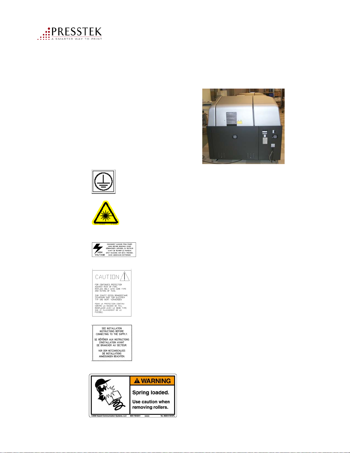
Introduction et
information sur la sécurité
Vector FL52AL électrique étiquettes d'avertissement
.
Il existe plusieurs normes de
sécurité et des étiquettes
d'avertissement situé à l’arrière
du Vector FL52AL:
Symbole de sol: situé à l'intérieur du panneau arrière
près du sol goujon.
Etiquette de sécurité avec un symbole de laser situé sur le panneau
supérieur arrière.
Etiquette d’avertissement de haut voltage situé sur le panneau
arrière, en bas à droite.
Etiquette de mise en garde pour le remplacement de fusible situé
sur le panneau arrière de l'appareil à proximité du panneau indicateur.
Instructions d'installation située près de cordon d'alimentation
de sortie sur le panneau arrière.
Cette étiquette se trouve l'intérieur de l’unité de lavage
pour enlever et remplacer les rouleaux de brosse et les
rouleaux de caoutchouc de transport.
Vector FL52AL Operator Manual
26
Page 27
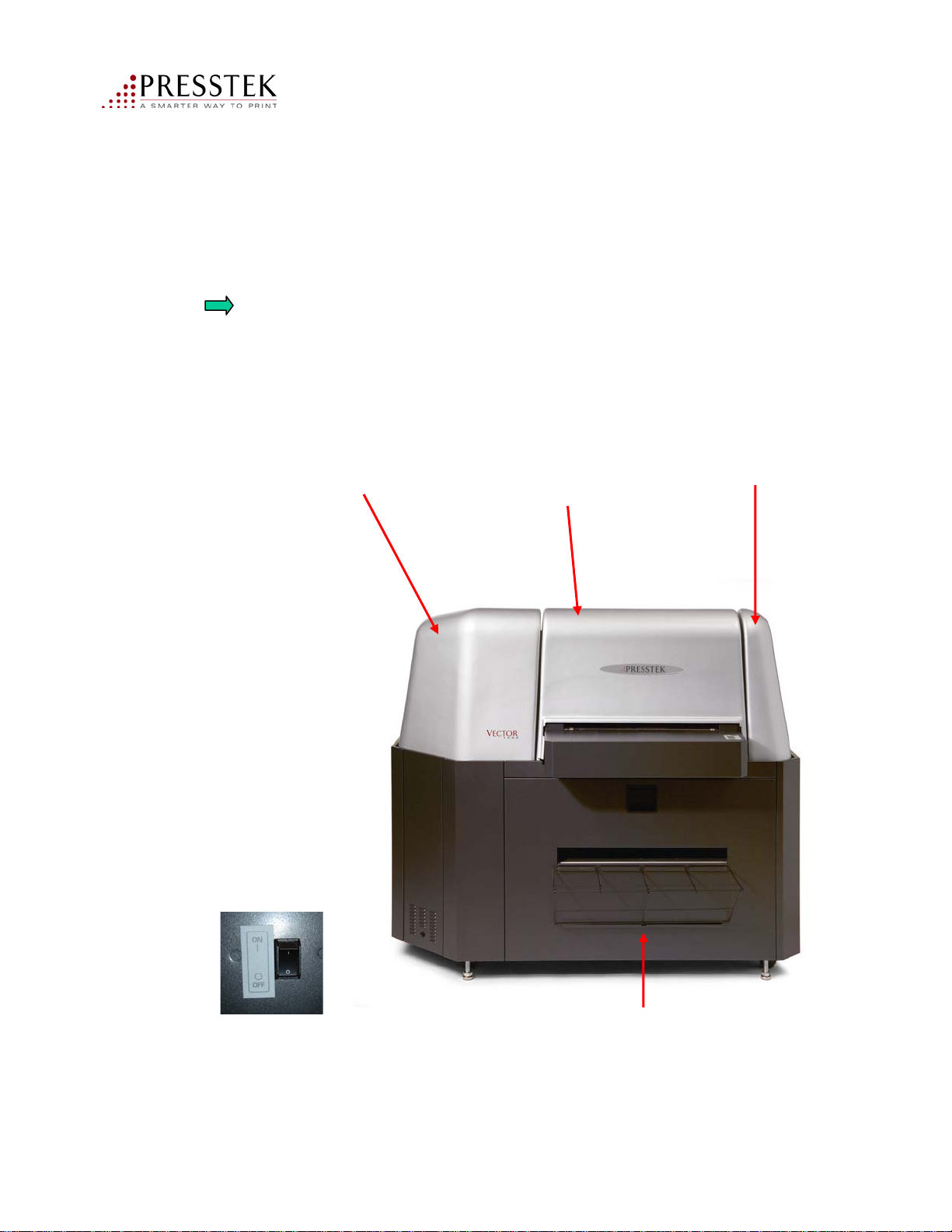
On / Off et interrupteurs de sécurité Interlock
Dispositifs de sécurité: S’il vous plaît se référer à l'illustration qui identifie et
décrit la fonction des dispositifs de sécurité utilisés sur le Vector FL52AL.
Ne pas faire fonctionner l'unité sans que toutes les couvertures, interrupteurs, et
dispositifs de sécurité soient dans leur position originale d’installation en usine.
Introduction et
information sur la sécurité
Couvercle de gauche
INTERLOCK SWITCHES
Un moteur et un
Laser Interlock Switch
situé sous ce couvercle.
Couvercle de Centre
(Garantis par des moyens
mécaniques baseframe avec
du matériel pour l'accès
autorisé par Technicien de
service)
Couvercle de droite
INTERLOCK SWITCHES
Un moteur et un
Laser Interlock Switch
situé sous cette couverture
ON / OFF / Circuit Breaker (15A)
situé sur le panneau arrière
Vector FL52AL Operator Manual
INTERRUPTEURS D’INTERDICTION POUR
L’ACCES AU TITOIR DE NETTOYAGE
Deux interrupteurs d'interdiction sont désactivés
lorsque le tiroir est ouvert. Le Chauffe-eau, la pompe
et les moteurs AC sont désactivés.
27
Page 28

Cette page est laissee intentionnellement en blanc
Vector FL52AL Operator Manual
28
Page 29

Kapitel 1
Einleitung und Sicherheitsinformationen
Vector FL52AL Operator Manual
29
Page 30

Einleitung und
Sicherheitsinformationen
Willkommen
Herzlichen Glückwunsch zum Kauf des Vector FL52AL. Dieses Direct-to-Metal CTPGerät verfügt über die kombinierten Vorteile der ausgezeichneten virtuellen TrommelTechnologie (ThinDrum), „Surefire“ Laser-Technologie und verleiht Ihnen die Vorteile
des letzten Standes der Technik bei diesem Plattenbelichter.
Über dieses Handbuch
Dieses Handbuch enthält wichtige Informationen über die Installation, Konfiguration und
den täglichen Gebrauch der Vector FL52AL, einschließlich der Arbeitsverfahren mit
Freedom Pro Metallplatten.
Jedes Kapitel dieses Handbuches hat einen besonderen Schwerpunkt. Die Informationen
in diesen Kapiteln sind angeordnet um höchste Leserfreundlichkeit und Verständnis zu
garantieren und führen zur effektivsten Benutzung des Vector FL52AL.
Kapitel 1: Einführung & Sicherheit Information
Dieses Kapitel beschreibt relevante Informationen über den sicheren Betrieb der
Vector FL52AL, Spezifikationen über das Gerät und auch, wie Sie dieses Handbuch so
effektiv möglich benutzen können.
Kapitel 2: Spezifikationen
In diesem Kapitel finden Sie Spezifikationen für die Vector FL52AL Plattebelichter und
Freedom Pro Platten.
Kapitel 3: Bedienung
Dieses Kapitel erklärt Prozeduren für den täglichen Gebrauch des Vector FL52AL.
.Kapitel 4: Wartungsarbeiten
Dieses Kapitel beschreibt die Wartungsarbeiten, die in regelmäßigen Abständen
durchgeführt werden müssen.
Kapitel 5: Fehlersuche
Dieses Kapitel beschreibt Warnungen und Fehlermeldungen.
Vector FL52AL Operator Manual
30
Page 31

Einleitung und
Sicherheitsinformationen
Kapitel 6: Freedom Pro Platten
Dieses Kapitel beschreibt die Freedom Pro Platte und enthält eine Liste der verfügbaren Größen.
Anhang A:
Liefer-und Bestellnummern.
Konventionen in diesem Handbuch
Bestimmte Konventionen sind angewandt worden, zur besseren Darstellung der Informationen in
diesem Handbuch.Die folgenden Schriften und Sonderzeichen werden überall in der
Betriebsanleitung verwendet:
Text in Fettgedruckten stellt ein Menü, Titel, Menüpunkt oder Kontroll-Element in einem
Dialogfeld da.
Text in Fettgedruckter Maschinen Schrift stellt wörtliche Informationen da, die genau
so eingegeben werden müssen, wie in diesem Handbuch dargestellt.
Text in kursiv innerhalb eines Satzes, ist wichtige Information und sollte sorgfältig gelesen werden.
Text dem ein Pfeil vorabgeht, ist wichtige Information über das behandelte Thema und sollte
sorgfältig gelesen werden.
Annahmen
Dieses Handbuch setzt voraus, dass man mit gewissen Kenntnissen der digitalen
Druckformenherstellung vertraut ist, sowie über grundlegende Kenntnisse des Microsoft
Windows Betriebssystems verfügt.
Installieren der VECTOR FL52AL
Die Hard- und Software Installation muss von einem autorisierten Service- Techniker ausgeführt
werden in Übereinstimmung mit den Installationsanweisungen im Servicehandbuch und in
Übereinstimmung mit nationalen und lokalen Vorschriften betreffend der elektrischen
Sicherheit.
Vector FL52AL Operator Manual
31
Page 32

Einleitung und
Sicherheitsinformationen
Sicherheitshinweis
Der Vector FL52AL ist ein nach Klasse 4 bewertetes elektrisches Gerät (nach
EN 60825-1: 1994) und muss an ein ordnungsgemäß geerdetes, drei (3)- adriges Stromkabel
angeschlossen werden in Übereinstimmung mit nationalen und lokalen Verordnungen. Beim
nicht erfüllen dieser Vorschrift, entsteht Gefahr eines tödlichen Stromschlags.
Der Vector FL52AL muss an einen eigenen, gesicherten Stromkreis angeschlossen werden..
Das Netzkabel für den Anschluss des Gerätes an die Stromversorgung muss in
Übereinstimmung sein mit nationalen und lokalen Normen und muss für einen Nennstrom
von 20 Ampere. (N.A.) / 16 Amp. (Europa) geeignet sein.
Industrierichtlinien
Niederspannungs-Richtlinie 73 / 23 / EWG für die folgenden Standards:
EN61010-1: 2001 Sicherheitsanforderungen für elektrische Ausrüstungen für Mess-,
Kontroll-und Laborzwecke - Teil 1: Allgemeine Anforderungen
CAN/CSA-C22.2 No. 61010-1-04
UL 61010-1: 2004
Electromagnetic Compatibility
FCC-Verifikation Teil 15-B, Klasse A
EMV-Richtlinie 89/336/EWG die folgenden Standards: EN61326: 1997 + A1: 1998 + A2:
2001
EN61000-4 (1994-96)
Achtung: Führe keine anderen Justierungen oder Prozeduren durch,
als im diesem Bedienerhandbuch beschrieben.
Vector FL52AL Operator Manual
32
Page 33

Einleitung und
Sicherheitsinformationen
Hinweis für Benutzer:
Schützen Sie sich selbst, Andere, und Ihre Geräte durch Beachtung aller
sicherheitswarnungen in diesem Handbuch. Bevor Sie versuchen den Vector FL52AL zu
betreiben, sollten Sie sicher sein, dass jeder Bediener gründlich vertraut ist mit diesem
Handbuch und jeder die Bedienungsanweisungen und Sicherheitswarnungen gelesen hat.
Lesen und Beachten Sie alle Warnhinweise:
Manipulieren Sie nie die Sicherheitsvorkehrungen vom Gerät, entfernen Sie nie
Sicherheits- Abschirmungen oder -Paneelen, und / oder versuchen Sie nie die
Sicherheitsschalter (interlock switches) außer Wirkung zu stellen. Unter keinen
Umständen sollten Sie versuchen, die Maschine zu bedienen, ohne dass die
Verriegelungen und andere Sicherheitseinrichtungen sich in ihren ursprünglichen,
werkseitig installierten Zustand befinden.
Presstek empfiehlt, Reparatur und Wartung Ihrer Maschine nur ausführen zu lassen von
einer qualifizierten Presstek Service Vertretung oder von einem autorisierten Händler /
Distributor.
Es wird davon abgeraten Reparatur oder Wartung dieses Gerätes durch nicht technisch
geschulten Besitzer oder Bediener oder nicht autorisiertes Service-Personal durchführen
zu lassen, wegen der Gefahr für die Sicherheit und der Möglichkeit dadurch
Garantieansprüche zu verlieren.
Überfülle nie den Wassertank (siehe Füllanleitung). Seien Sie vorsichtig,
vermeiden Sie das Auslaufen von Wasser, wenn Sie Wasser nachfüllen, oder wenn Sie
den Plattenreiniger in oder aus der Maschine schieben..
Verwenden Sie in keinem Fall destilliertes Wasser um den Wassertank zu
befühlen.
Unter keinen Umständen sind die Sicherheitsschalter in Tür oder Abdeckungen
unwirksam zu machen.
Vector FL52AL Operator Manual
33
Page 34
Vector FL52AL Elektro-Warnhinweise
Es gibt mehrere verbindliche
Sicherheitsaufkleber und
Warnhinweise auf der
Rückseite der Vector FL52AL:
Aufkleber für Masse Symbol: Der Aufkleber befindet sich im Inneren der
Rückseite, im Bodennähe beim Masse Anschluss.
Lasersicherheit Aufkleber: am oberen Rückwand.
Einleitung und
Sicherheitsinformationen
Hochspannungsaufkleber: am Rückwand, unten rechts.
Warnung Sicherung austauschen Aufkleber auf das Rückseite Paneel
in der Nähe der Sicherungstabelle.
Installationsanweisungen in der Nähe des Netzkabelanschlusses auf
dem Paneel an der Rückseite.
Dieser Sicherheitsaufkleber befindet sich
in dem Plattenreiniger, für eine vorsichtige Entfernung
und Ersatz der Bürsten und anderer Transportwalzen.
Vector FL52AL Operator Manual
34
Page 35
Einleitung und
Sicherheitsinformationen
Ein / Aus und Sicherheitsschalter
Sicherheitsvorkehrungen: Bitte beachten Sie die Abbildung. Diese identifiziert und
beschreibt die Funktion der Sicherheitsvorkehrungen des Vector FL52.
Verwenden Sie das Gerät nicht ohne alle Abdeckungen, Verriegelungen, und
Sicherheitseinrichtungen in ihren ursprünglichen, werkseitig installierten Positionen.
Abdeckung der linken Seite
Sicherheitsschalter
Ein Motor- und einen
Mitte-obere Abdeckung
Mechanisch gesichert mit
Schrauben. Für den
Zugriff durch
autorisierteServiceTechniker.
Abdeckung der rechten
Seite.
Sicherheitsschalter
Ein Motor und ein
Laser-Sicherheits-Schalter
unter dieser Abdeckung.
EIN / AUS
Schalter /
Automatische
Sicherung
(15A)
befindet sich
auf der Rückseite
Vector FL52AL Operator Manual
Plattenreiniger Zugang,
Schublade, Sicherheitsschalter
Zwei Interlock-Schalter
deaktivieren Heizung,
Pumpe und Antriebsmotoren
wenn die Schublade
geöffnet wird.
35
Page 36

Einleitung und
Sicherheitsinformationen
Diese Seite wurde absichtlich leer gelassen.
Vector FL52AL Operator Manual
36
Page 37
Chapter 2
Specifications
Vector FL52AL Operator Manual
37
Page 38

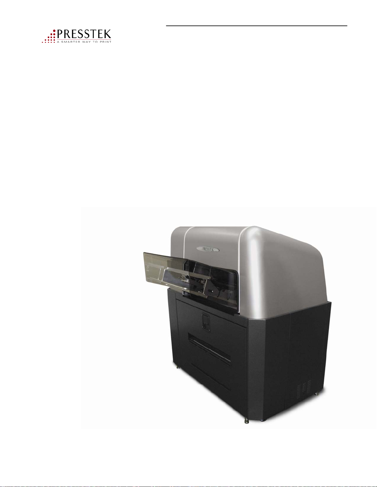
Vector FL52AL Specifications
Imaging Technology Internal five rib drum
Laser Technology Presstek SureFire – Class 4 laser product
Media Presstek Freedom Pro thermal plates
Media Supply Single sheet, semi-automated feed
Plate Length Minimum: 14.375˝ to 19.875˝ (365 to 505 mm)
Plate Widths Min. 11” to max. of 20.66”
Specifications
Maximum Image
Area 20.87˝ W x 19.165˝ L (530 x 487 mm)
Plate Thickness .006˝ and .008˝ (.15 and .20 mm)
Resolution / Screening 2400 dpi / Up to 175 line screen
Speed Up to 16 plates an hour
Plate Washer Integrated water wash with scrub rollers
Register System Dual internal register pin system
Operating Daylight-safe, 60 - 75˚F (15.5 – 23.8˚C)
Environment 30 - 70% relative humidity (non-condensing);
prepress or pressroom area
Electrical 200 to 240 VAC, 50/60 Hz, 20 amp,
Requirements single phase; NEMA L6-20R receptacle
Weight 1,000 lbs (454 kgs)
Dimensions (LxWxH) 58˝ x 29˝ x 52˝ (147 cm x 74 cm x 132 cm)
Vector FL52AL Operator Manual
38
Page 39
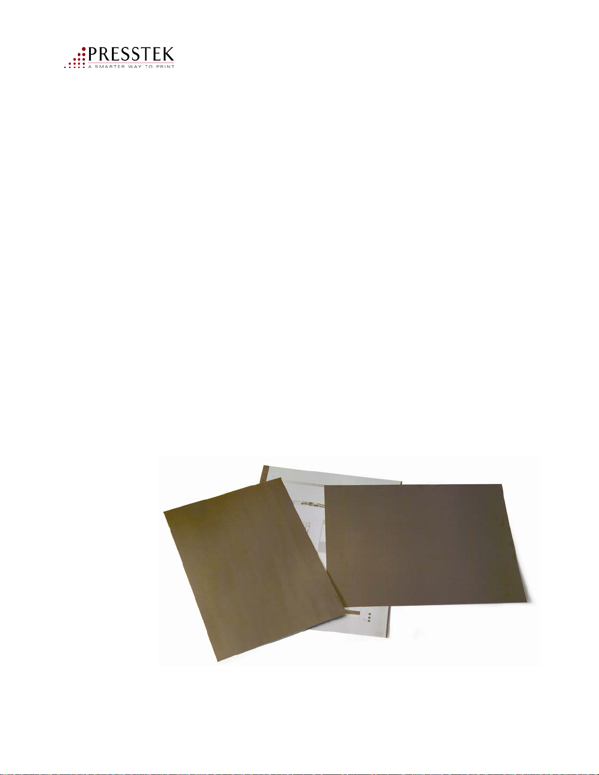
Freedom Pro Plate Specifications
Plate Type Chemistry-free, thermal positive writing
Plate Substrate Aluminum
Printing Mechanism Wet offset
Resolution 3%-97% @ 200 LPI
Length of Run Up to 25,000 impressions
Light Sensitivity 100% daylight safe – no safelight required
Specifications
Plate Thickness .006˝ and .008˝ (.15mm and .20mm)
Plate Size Standard 2-page formats, 52 cm and below
See pg. 60 for list of plate sizes
Processing Simple rinsing with only water
No baking or gumming required
Vector FL52AL Operator Manual
39
Page 40

This page intentionally left blank
Vector FL52AL Operator Manual
40
Page 41
Chapter 3
Operation
Vector FL52AL Operator Manual
41
Page 42
Getting Started
Overview
This chapter provides useful information about your Vector FL52AL. It will guide you to a basic
understanding of the main areas of the equipment and highlight those things that are important in
obtaining consistent quality results in a convenient manner.
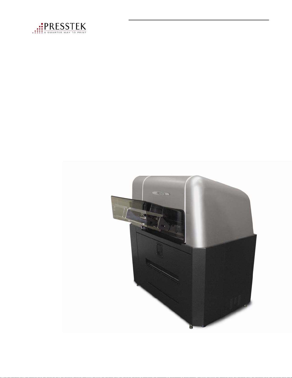
The Vector FL52AL (Autoloader) uses vacuum cups to automatically pick a plate from a stack of
plates on the input tray.
Plates need to be stacked carefully on the register pin and stops on the tray.
A plastic interleaf is placed between each plate in the stack. This is to keep plates from sticking
together in the stack.
The Vector FL52AL also uses air jets to almost completely dry the plate before flipping and stacking it in
the output tray. It is normal to have a few small droplets of water at the tail back edge of the plate at the
end of the process.
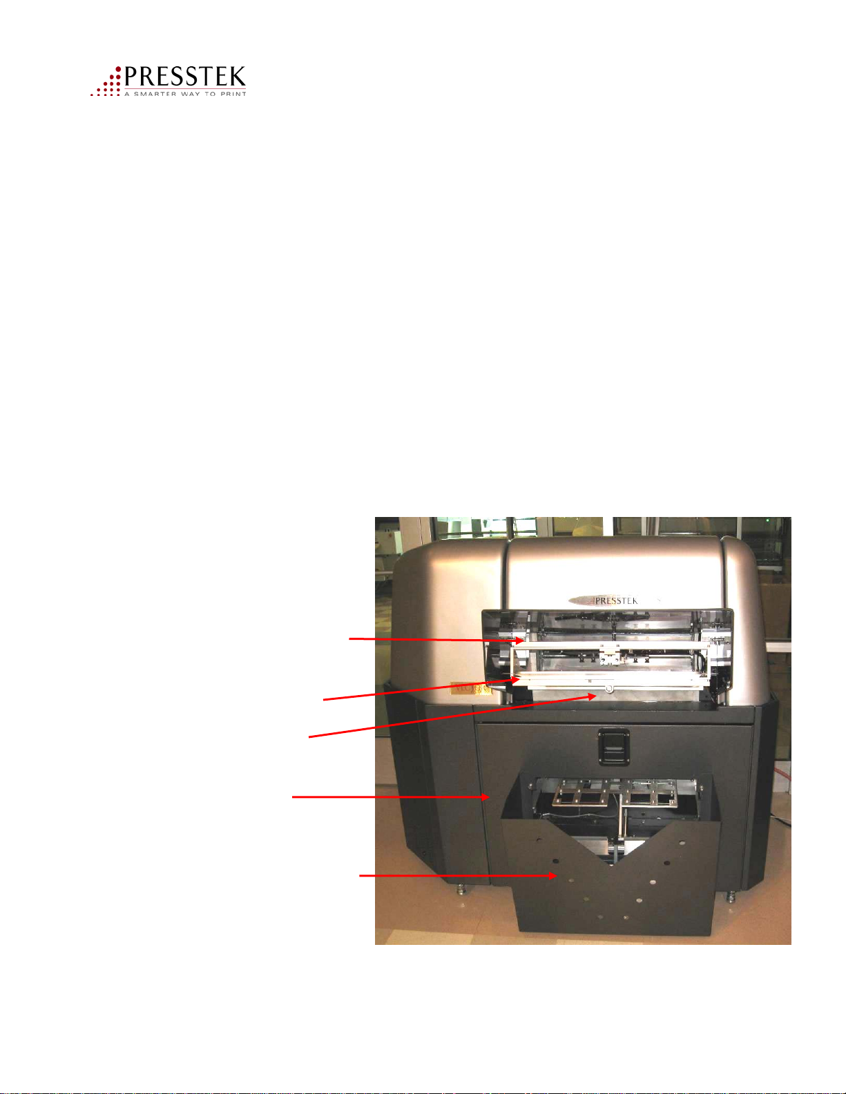
Locating the Major Areas
Plate View Cover
(Smoked plastic)
Plate input tray
Status Light/
Reset/Switch
Wash Unit
Plate Collection Tray
Status Light Note: Green = Good to go
Flashing Red = error - (Press once to reset)
No light = Manual mode - (Press once to reset)
Press and hold for 20 seconds to go into manual mode - (Press once to reset)
Vector FL52AL Operator Manual
42
Page 43
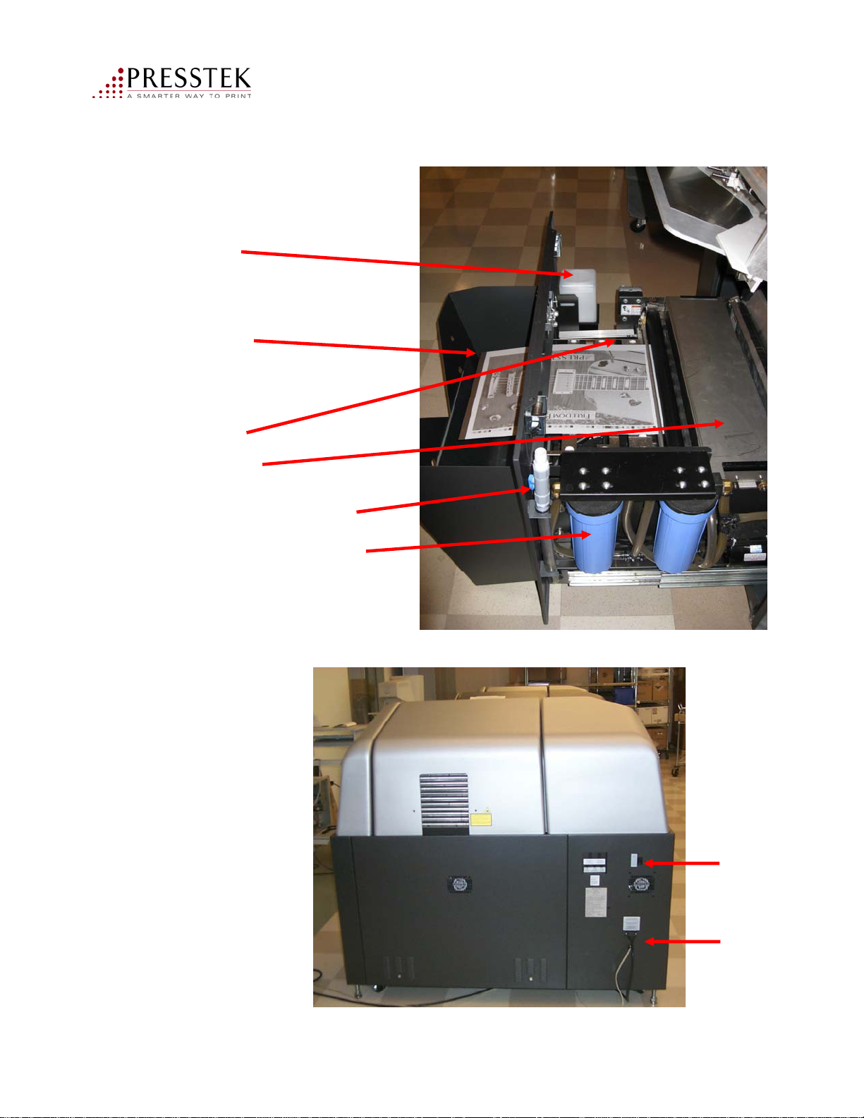
Locating the Major Areas
Wash Unit Drawer Shown in the
open position:
Water Reservoir
Plate output Ramp
Air Jet Drier Bars
Washer Splash Guard
Getting Started
Washer Drain Hose
Washer Water Filters
Rear of machine:
Power
On/Off
switch
Vector FL52AL Operator Manual
Power
Cable & USB
Cable
43
Page 44
Turning on the Vector FL52AL
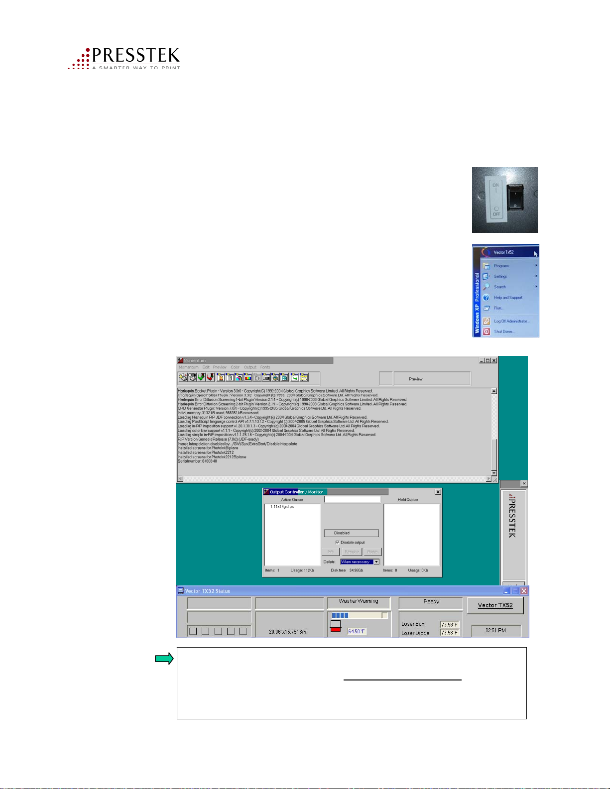
1. Power on the RIP workstation.
2. Log onto the workstation if auto logon is not enabled.
Login: Administrator Password: presstek
(Note: the password is lower case. Do not change.)
3. Press the power on switch on the back of the machine
to turn on the Vector FL52AL.
4. Click the Windows Start menu and select the
Vector FL52AL tab to start the software programs.
5. The computer screen will launch the RIP and the
Vector FL52AL status panel as shown:
Loading a Plate
NOTE:
Vector FL52AL Operator Manual
If you need to power on the CTP device immediately after
powering it off, you must wait at least 30 seconds to prevent
damage and to make sure that it will reconnect properly with
the RIP workstation
44
Page 45
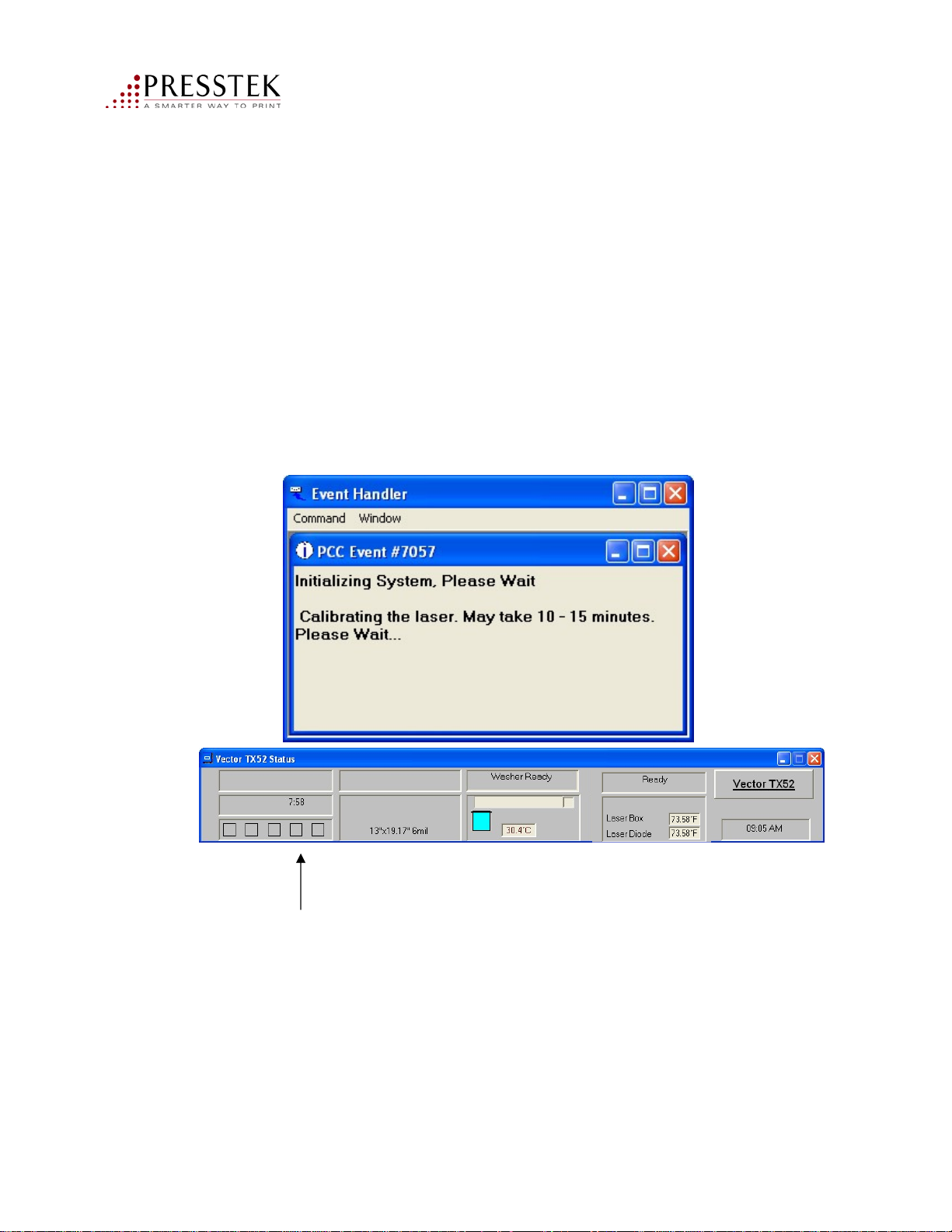
Note: Laser Calibration Interval
The Vector FL52AL laser system performs a self-calibration procedure
every 24 hours. This activity sets the imaging current over 10-15 minutes.
While this is happening, the time remaining is displayed.
Depending on how and when the machine is shut down, you may
or may not see this action.
Loading a Plate
Time remaining show here
Vector FL52AL Operator Manual
45
Page 46
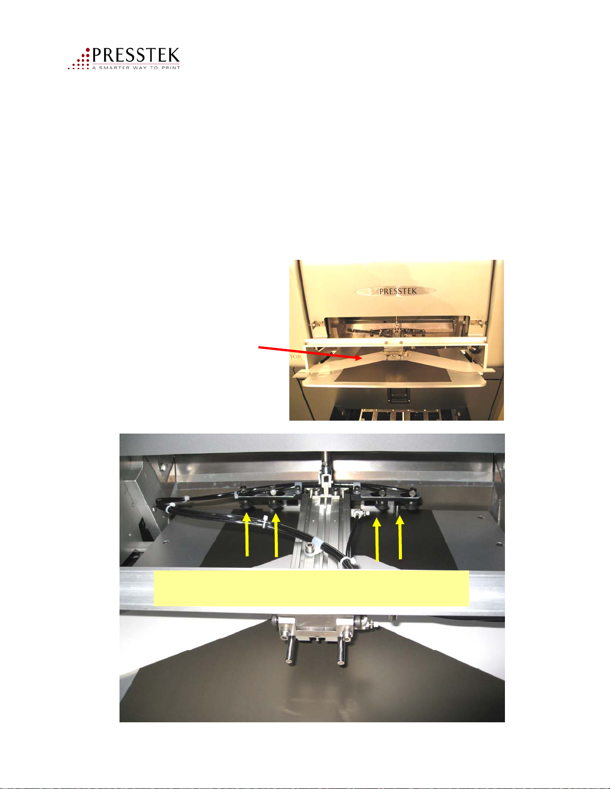
Loading a Plate
Loading Plates Using the Autoloader:
Important Note: When loading plates onto the input tray, care must be taken to seat
the plates onto the registration pin and against the plate stops.
1. Interleafs (may vary in color) should be inserted between each plate.
2. Load plates in reverse order of imaging.
Plate interleaf
Vector FL52AL Operator Manual
Use care to ensure that plates are
seated onto the registration pins and against
the plate stops.
46
Page 47
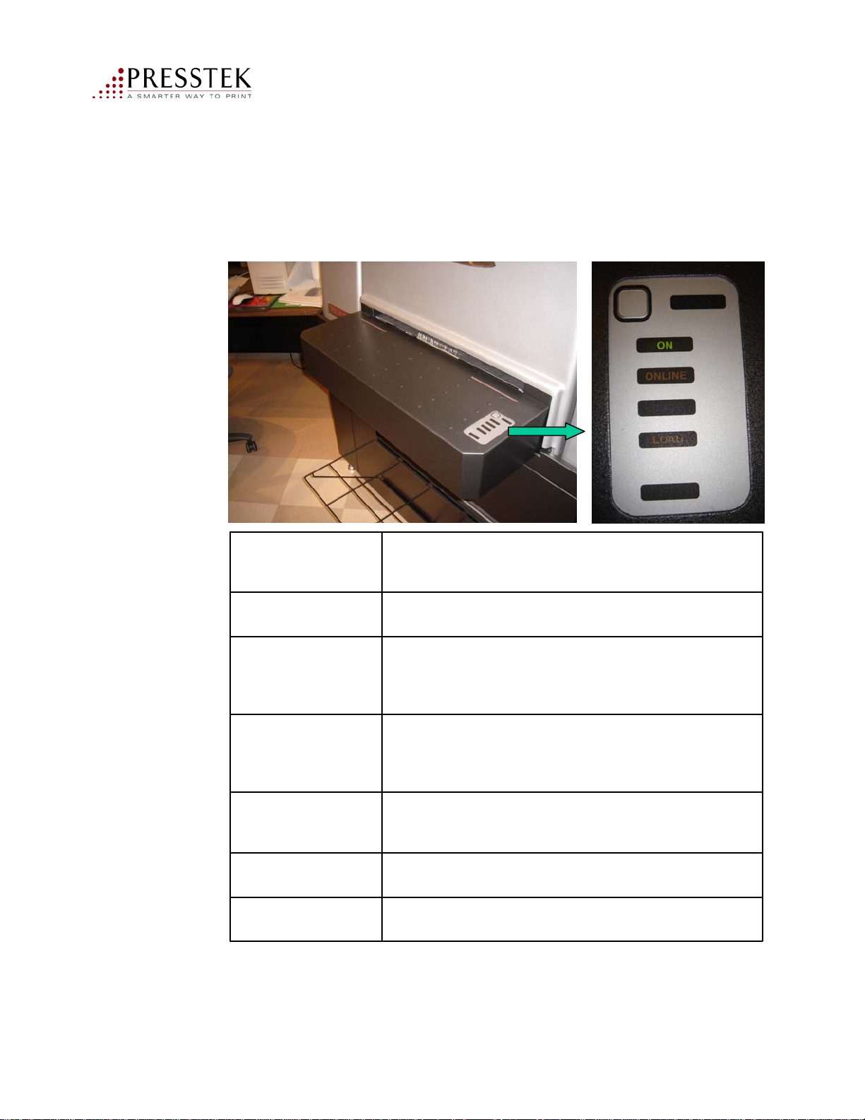
Vector FL52AL Status Panel
The panel messages indicate the operational status of the Vector FL52AL.
Getting StartedGetting Started
On
Online
Busy
Load
Unload
Registered
FunctionMessage
On: machine is powered on
Off: machine is powered off
On : machine is in normal plate making mode
Off: machine is in diagnostics mode
Flashing: machine is not communicating with computer (or
computer/software not running)
On: There is a plate in the machine. Do not open the covers or
drawers
Off: It is safe to open the washer drawer (e.g. to replenish the
water)
On: Ready to accept new plate
Off: The drum is not ready to accept a plate
Flashing: Loading a plate
On: the unload function is available via the panel push button
Off: the panel push button is not active
On: a plate is registered on the input tray
Off: no plate or not registered properly
Vector FL52AL Operator Manual
47
Page 48
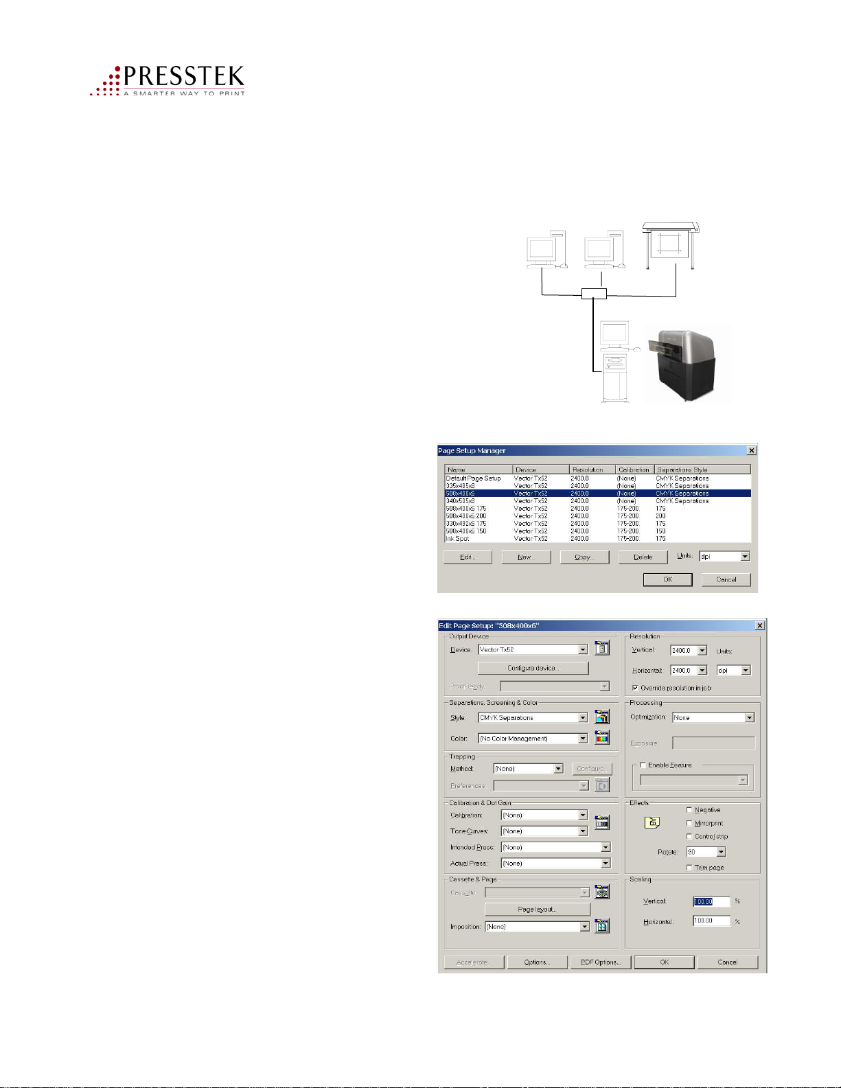
How the System Works:
Print jobs are created on Macs
and PCs using popular desktop
publishing applications.
Files can be digitally proofed
for color and layout prior to
plate imaging.
Files are printed to the
Vector FL52AL RIP into
a Page Setup.
The Page Setups contain
parameters for line screen
ruling, dot shape, calibration,
and plate size.
Getting StartedGetting Started
MAC PC Proofer
Vector FL52AL
Please refer to the
Momentum RIP
Quick Start Guide for
more detailed
information.
Sample list of Page Setups
Vector FL52AL Operator Manual
Sample Page Setup screen
48
Page 49
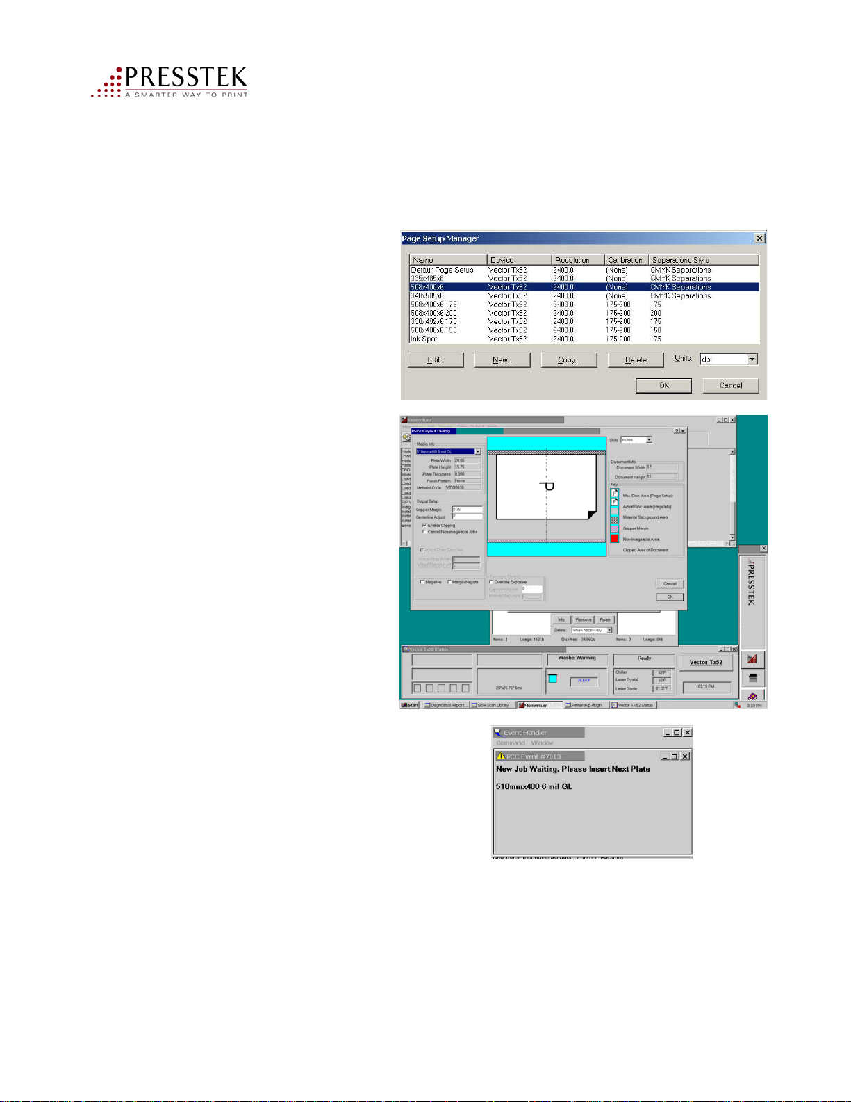
How the System Works:
The RIP’s Page Setup
Manager can contain a
variety of RIP scenarios
for different plate sizes
and line screen rulings.
At the Vector FL52AL,
the operator can view
the job layout on the
plate prior to imaging.
Getting StartedGetting Started
The Vector FL52AL
status panel prompts the
operator to insert a plate,
and automatically tries to
Load the plate. Feedback is
Provided throughout
the imaging process.
Vector FL52AL Operator Manual
49
Page 50
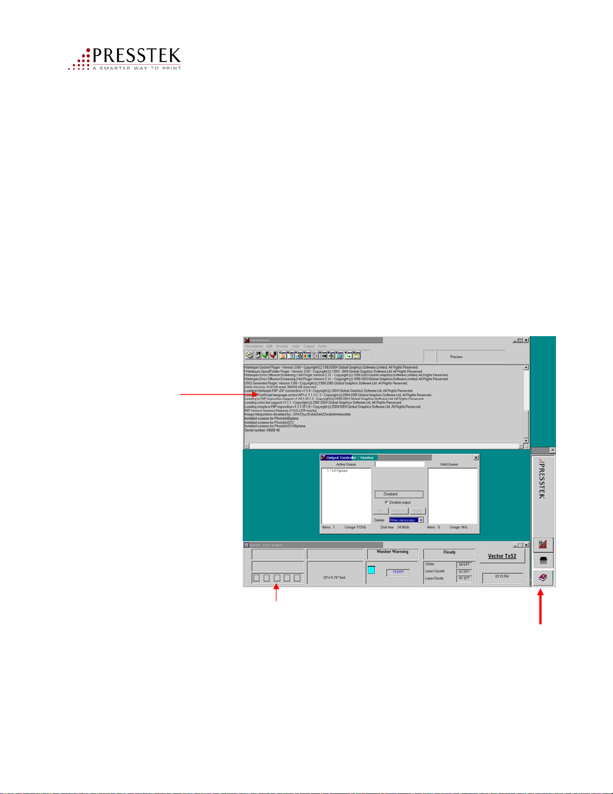
RIP Workstation Description
The RIP Workstation consists of 6 major parts:
Computer
Monitor
Keyboard
Mouse
RIP dongle (USB device)
Machine dongle
NOTE: The RIP dongle is the security key that enables your RIP program.
If the dongle is lost, a new one must be purchased at full price.
Three major software programs combine to operate your Vector FL52AL:
The RIP:
used to process
your printing
jobs.
The Vector FL52AL Status bar:
used to control the equipment
Vector FL52AL Operator Manual
The Launch bar:
displays icons that
can be used to start
the Vector FL52
status bar, the RIP
queue and access
online manuals
50
Page 51
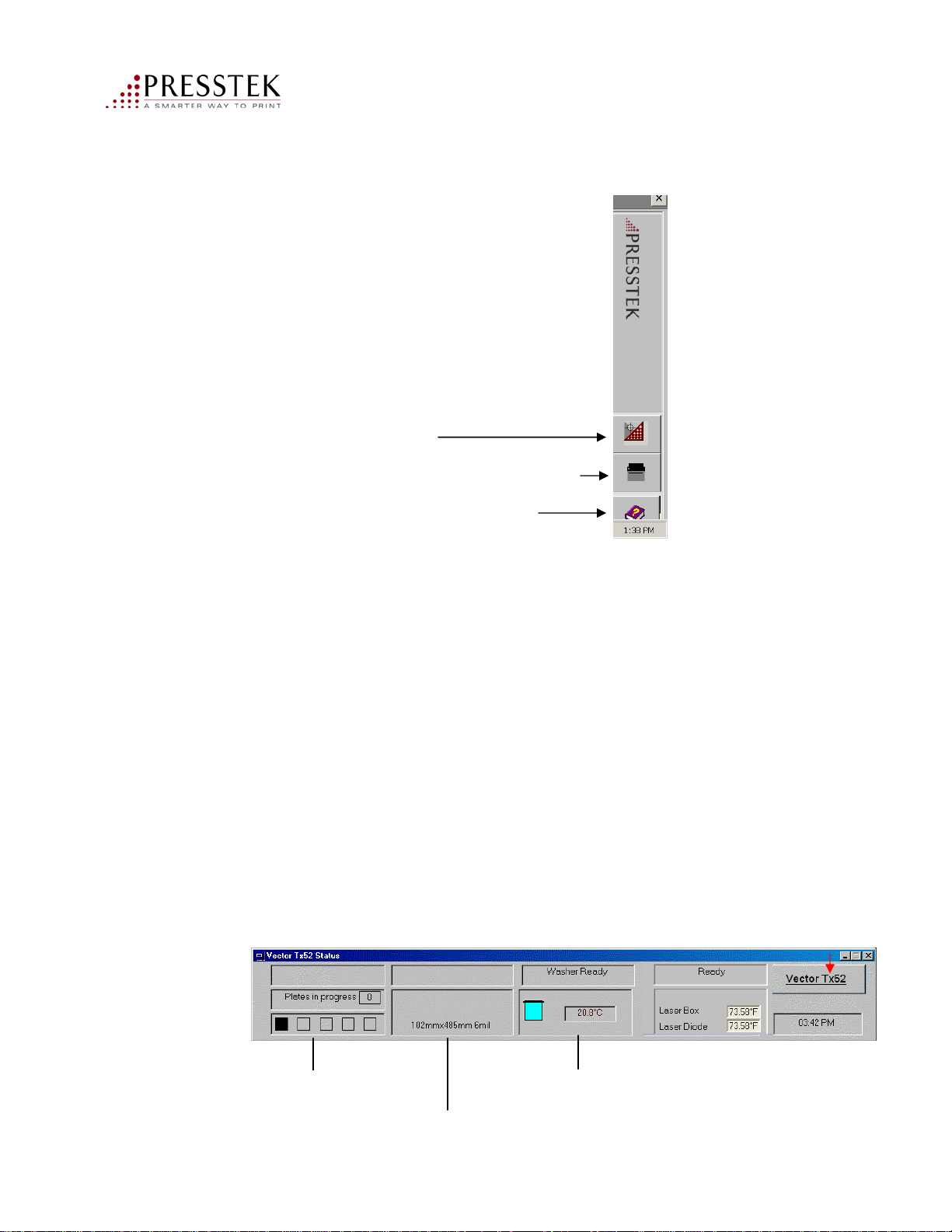
Launch Bar Descript ion
Starts the RIP program.
Click here to see the Vector FL52AL status bar.
Opens a copy of your operator manual
Vector FL52AL Status Panel Description
The Vector FL52AL Status bar contains status information and controls used to
operate the platesetter. From this status bar you can:
• Monitor the status of the CTP device
• Set preferences
• Customize the media data base
• Monitor the plate usage
System
Media Indicators
Media Menu Button
Media size/thickness
Washer/Filter Imaging
Washer ready/
filter change
51
Vector FL52AL Operator Manual
Page 52
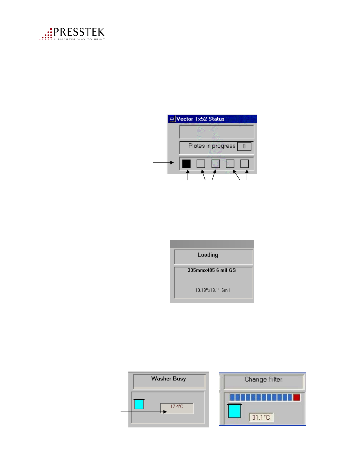
The System panel
This panel displays the general CTP state and the number of plates (or images) in
progress. In addition, the “media progress indicators” will let you know where the
current plates are.
Media Indicators
Media panel
The media panel displays the plate status (Clamped, Loading, etc). The last
selected media code is also displayed. Click on the media panel to open the
media data base window. See “Working with the Media Database;” pg. 59.
Drum Conveyor in/out Washer in/out
Washer/Filter panel
Displays the Washer state, the water level, temperature, and filter status.
The water level displayed in aqua indicates proper level, red indicates low
levels. If the level is too low, the plate will not be allowed to process. The
temperature is displayed in black if within operating range, blue if it is
below the required set point and red if it is too high. You will also be
prompted to change the washer filter after 200 plates.
Click on
temperature
to see the
set point
Vector FL52AL Operator Manual
52
Page 53
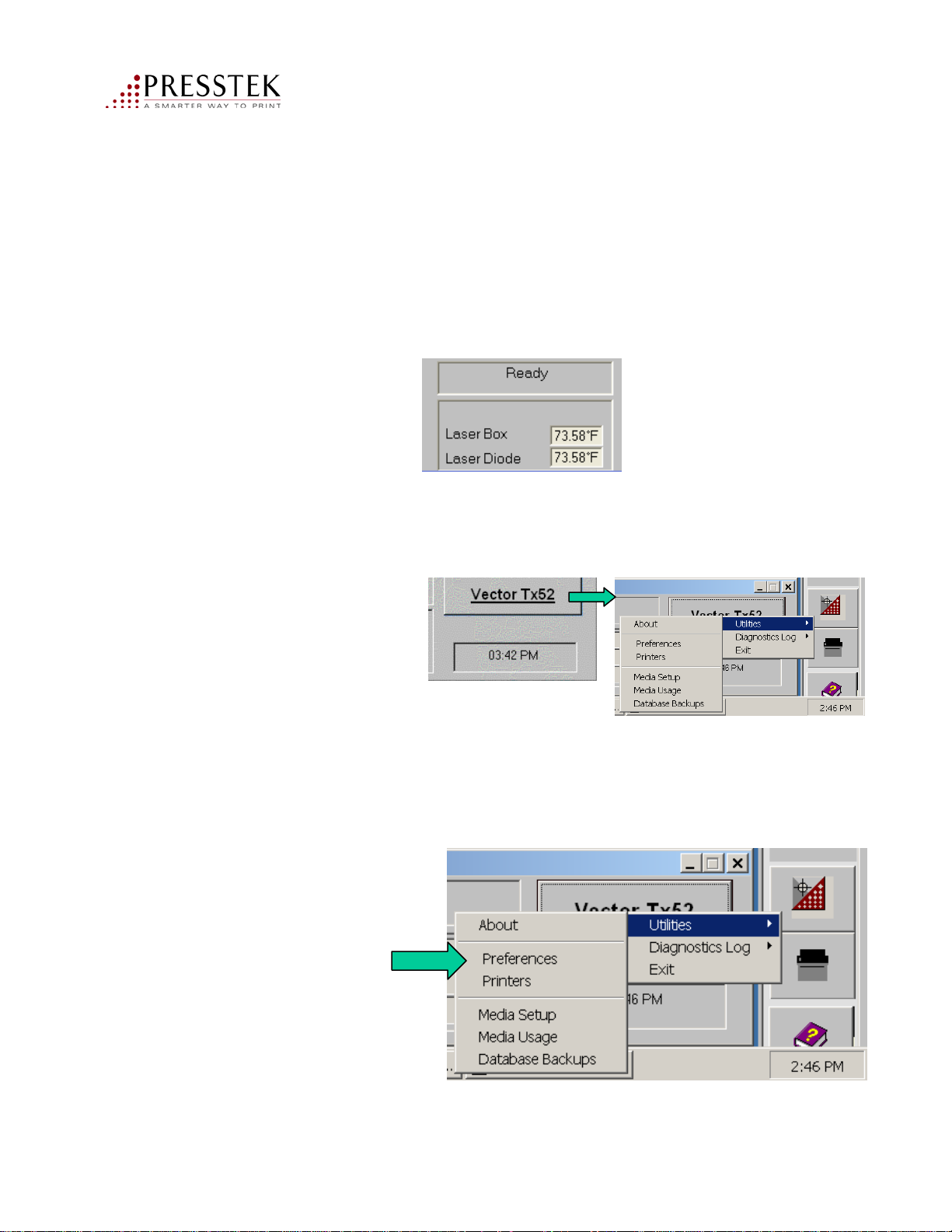
Imaging panel
The imaging panel displays the state of the imaging unit.
The temperatures of the imaging components are displayed in black when
within operating range, blue when below set point and red when above set
point.
Vector FL52AL Menu button
Click for additional
menus.
Click on any temperature
to see the set point
Setting Preferences
Use this menu button to select preferences. You can change the system units,
your login preferences or the RIP zoom options. Please see next page.
Vector FL52AL Operator Manual
53
Page 54
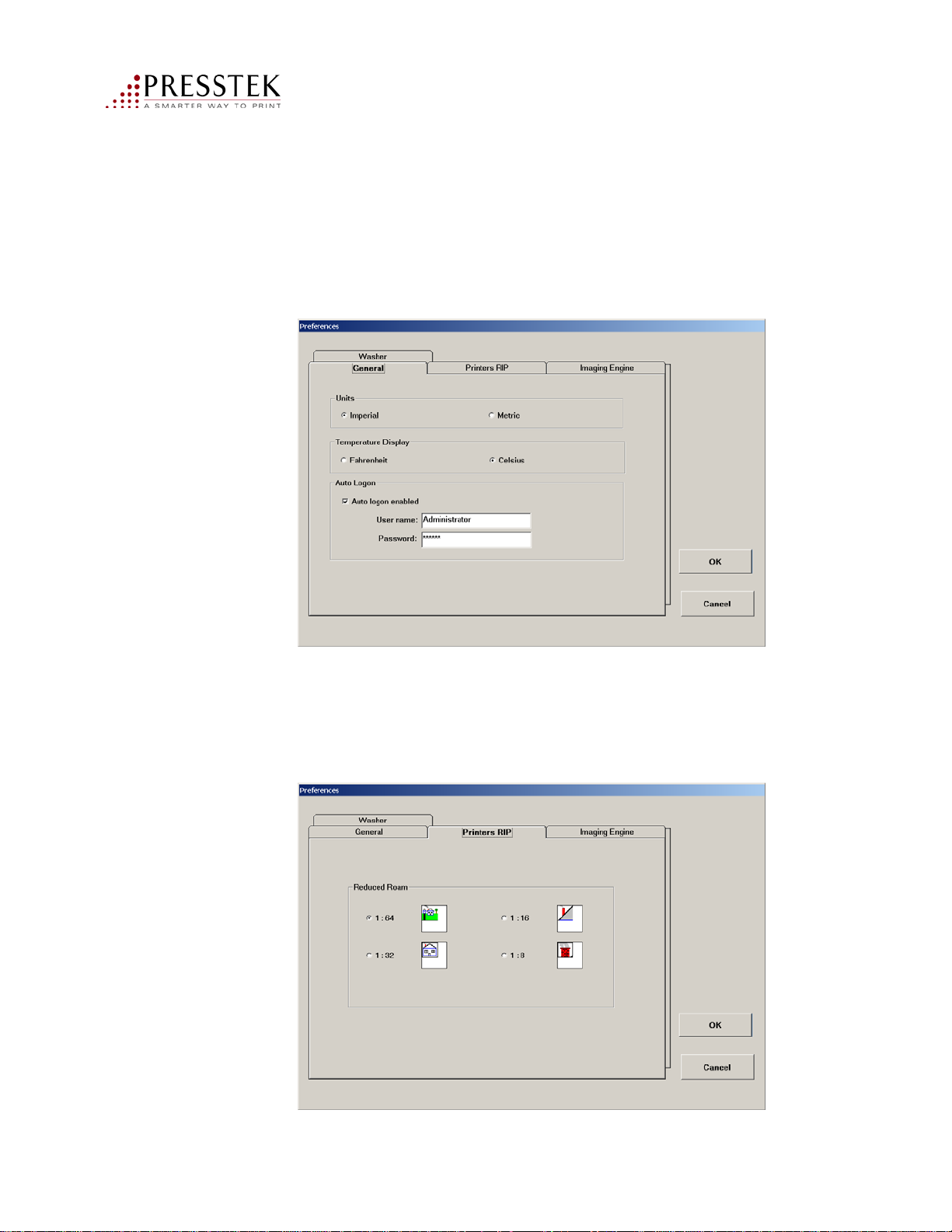
General Preferences
Units: Imperial (inches) or Metric will describe the plate size.
Temperature Display: will display the temperatures in Fahrenheit or Celsius.
Auto Logon: default is Auto logon enabled. Do not change the password.
RIP Preferences
Roam Window – Reduced Roam: This will display the image
at a reduced zoom level. For a job that is 11” x 17”, the 1:64 zoom
is recommended.
Vector FL52AL Operator Manual
54
Page 55
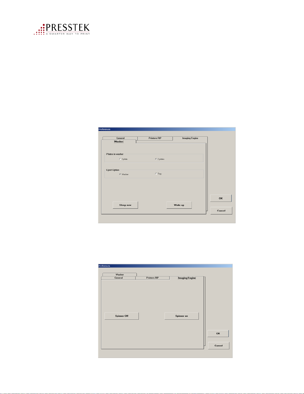
Washer Preferences
Plates in washer: 1 Plate is the default (recommended). If 2 plates is
selected, it will enable two plates to stack up on the exit tray (not recommended
due to the plate emulsion and possibility of plate scratching).
Eject Option: used by service personnel. Washer is the default. If tray
is selected, the machine will eject the plate back onto the loading tray and
not through the washer. The plate would then need to be washed by hand.
Sleep Mode: This will turn the washer off. The Washer will
come back on automatically when the next plate is imaged.
Imaging Engine: Spinner Off is used by Presstek-authorized
service personnel. Spinner on is the default.
55
Vector FL52AL Operator Manual
Page 56
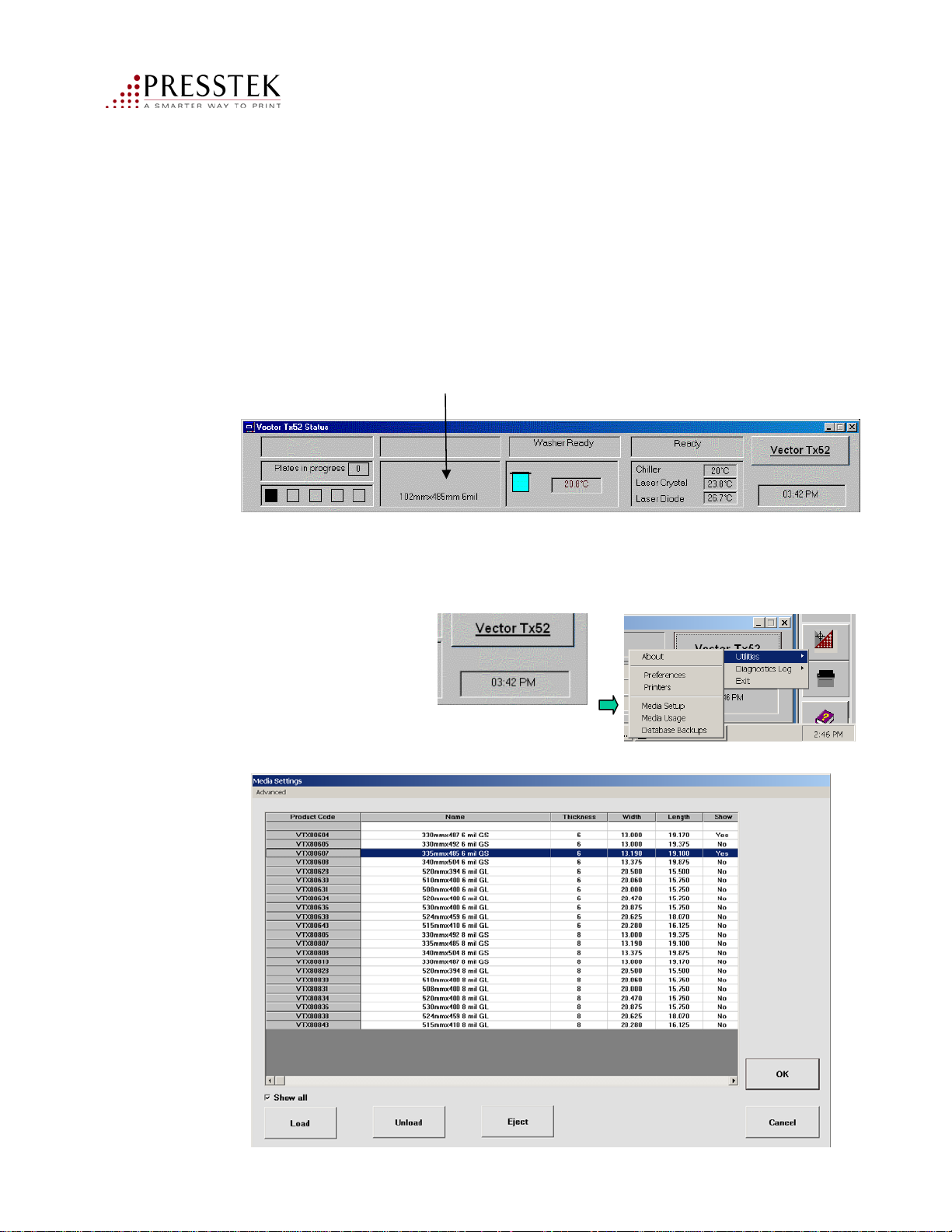
Working with the media database
The media database displays a list of all Freedom Pro plate product codes.
Opening the Database
Open the database window by using one of the following two methods
• Click on the media panel
OR
• Click on the Vector FL52 menu and select Media Setup
The Media Settings window appears:
Vector FL52AL Operator Manual
56
Page 57
Working with the media database
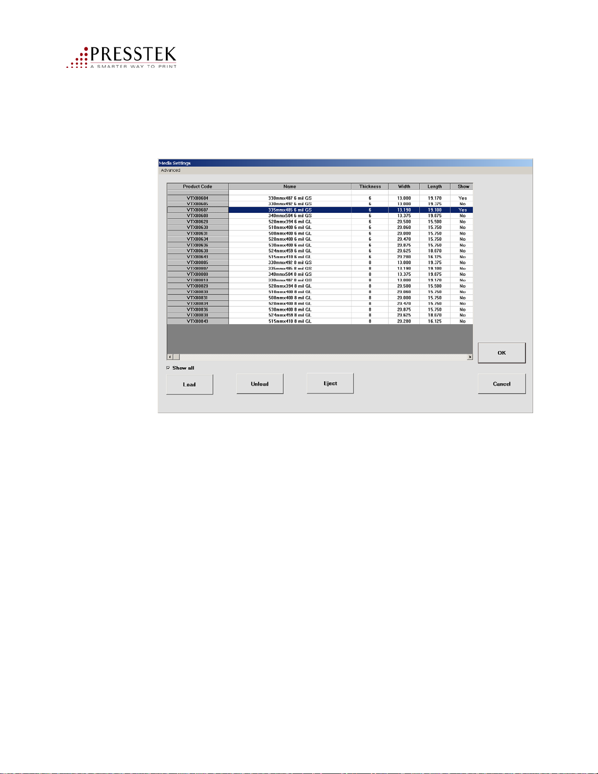
The Media Settings Window allows you to perform plate operations and
customize media codes.
Plate Operations:
Load: Loads a plate into the drum. It will prompt you to insert a plate if
not already clamped.
Unload: Returns the plate from the drum to the input tray.
Eject: If a plate is in the drum, it is fed to the washer
57
Vector FL52AL Operator Manual
Page 58
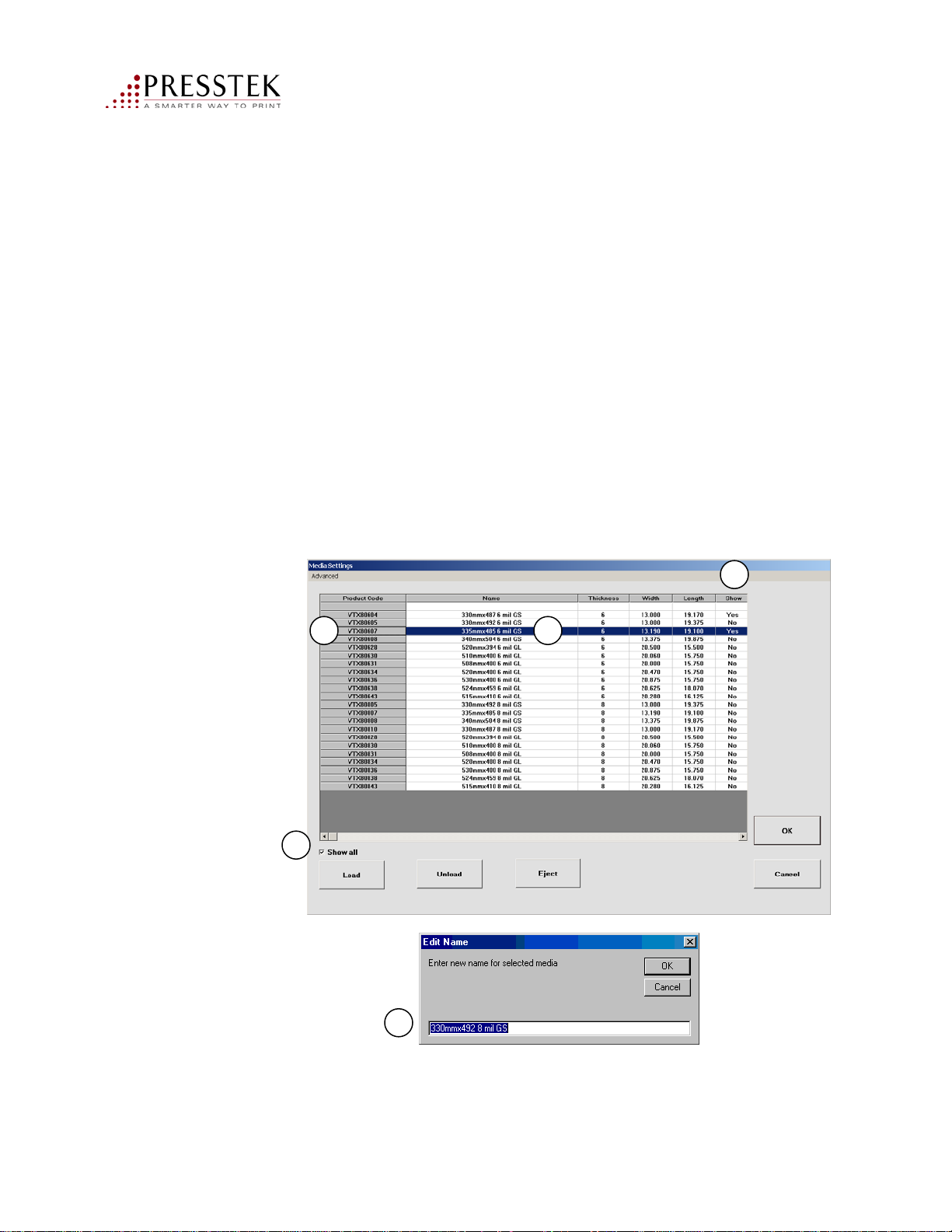
Customizing the media database
This will allow you to select a plate product and change its name for convenience.
For example, if you have a Ryobi press, you can change 330mm x 492 6 mil
to show as “Ryobi 6 mil.”
1. Check the Show All box
2. Select a plate from the list by clicking on the product code
3. Double-click in the Show column to set it to YES
4. Double-click in the Product Name column to enter a name of your
choosing.
5. Enter a name in the Edit Name window, then click OK.
3
2
1
5
4
Repeat steps 1-5 for each Plate type that you use.
Uncheck the Show all check box to only display the plates you are using.
Vector FL52AL Operator Manual
58
Page 59
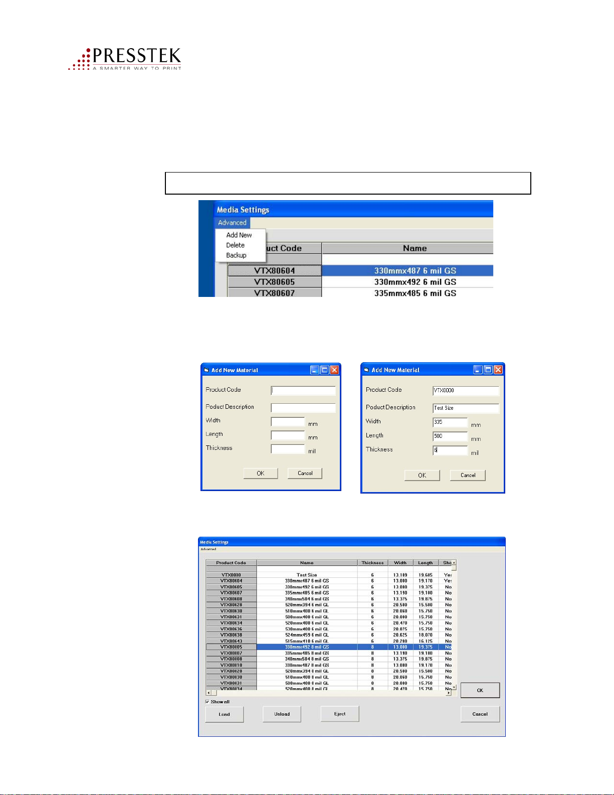
Creating a new plate item in the Media Database:
1. Click on Advanced>Add New.
Note: Product code prefix is now VFL. VTX is no longer a valid prefix.
2. Fill out the Add New Material form box, then click OK. For Product Code use
the number on the box label. Height and width dimensions are in millimeters only.
be sure to type in the plate thickness, also found on the box label.
3. Check the new entry in the Media Settings list, as shown:
Vector FL52AL Operator Manual
59
Page 60
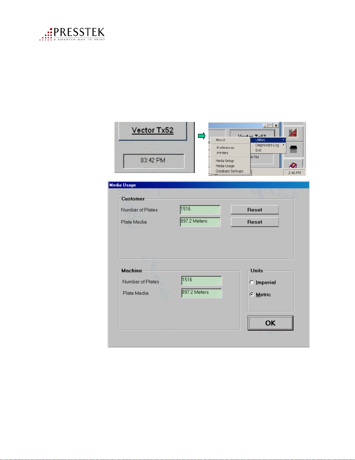
Displaying the Media Usage
To display the Media Usage window, click on the Vector FL52 menu>Utilities
and select Media Usage. Click Reset if you wish to reset either of the counters.
Vector FL52AL Operator Manual
60
Page 61

System Shutdown
1. Close all open applications and programs.
2. Click the Windows Start menu and select Shut Down. Wait for
3. Power off the Vector FL52AL by pressing the power switch on
computer to shut down completely.
the rear of machine.
Vector FL52AL Operator Manual
61
Page 62
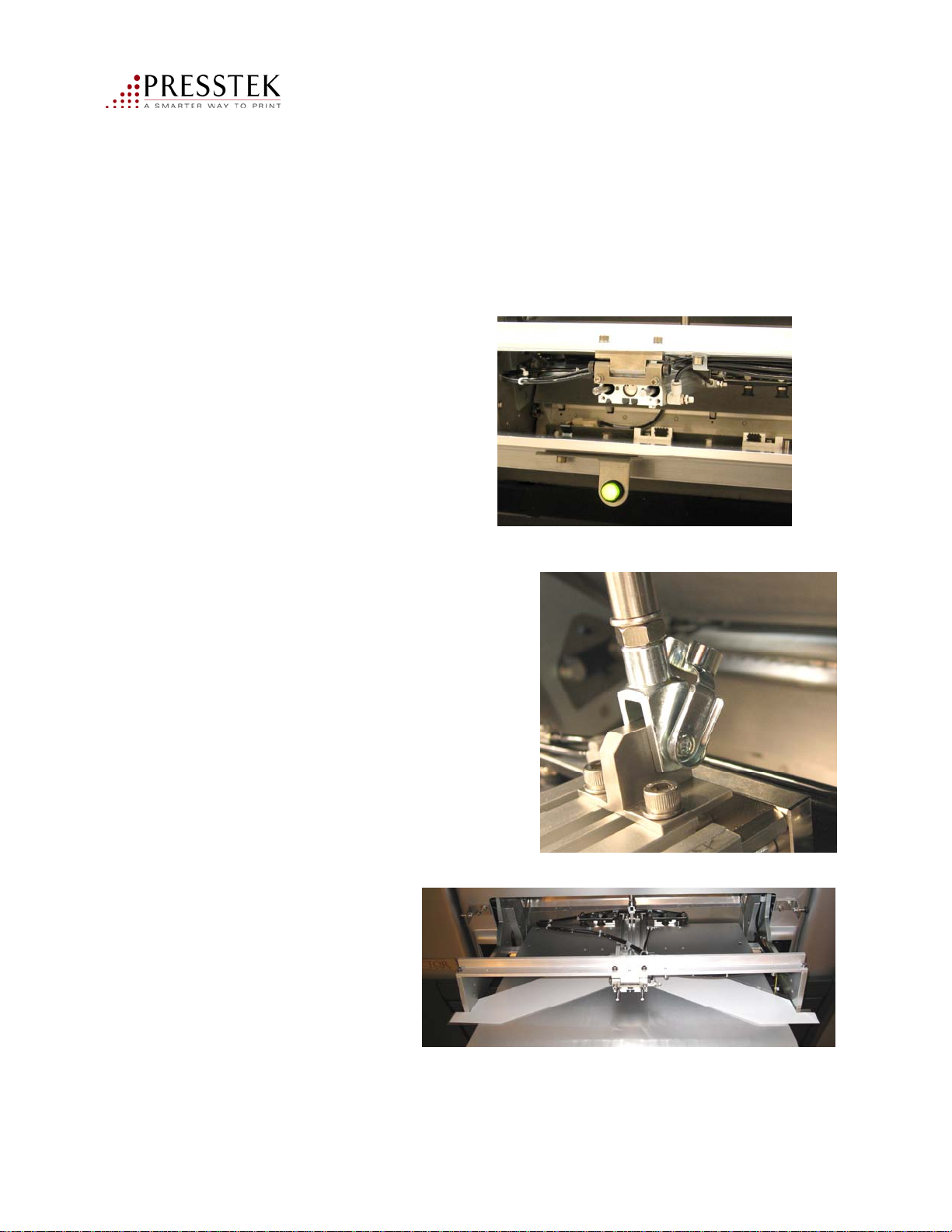
Manual Plate Loading Mode
The manual mode of operation is for use when the air supply is lost or some
other condition is prohibiting normal automatic plate loading.
1. Press and hold the Status Light/Switch
until the light goes out.
2. Remove the Clevis holding the in/out
air cylinder to the up/down air cylinder
by rotating the clip and sliding
the clevis out.
3. Remove the 2 screws
holding the rear cross brace
to the autoloader and
carefully place the
cross brace and air
cylinder aside.
Vector FL52AL Operator Manual
62
Page 63
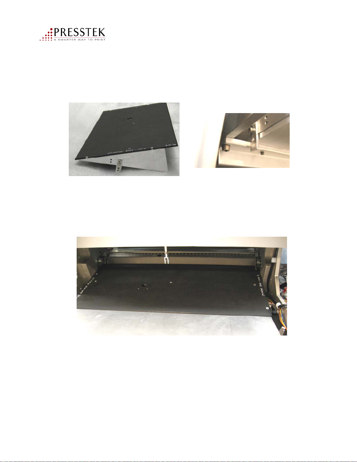
Manual Plate Loading Mode
4. Insert the manual platen onto the Plate Input Tray with the stops up against
the cross brace.
5. Plates can now be manually placed onto the registration pins for loading.
Vector FL52AL Operator Manual
63
Page 64
Chapter 4
Operator Maintenance
Customer Support: 1-800-422-3616
Vector FL52AL Operator Manual
64
Page 65
Operator Maintenance
The Vector FL52 platesetter is easy to maintain. The main activities involve
• maintaining adequate water supply for the washer
• periodic cleaning of the washing system to prevent buildup
• changing the washer filters
CAUTION: Do not attempt to perform any maintenance while the
Vector FL52 is imaging or unloading a plate
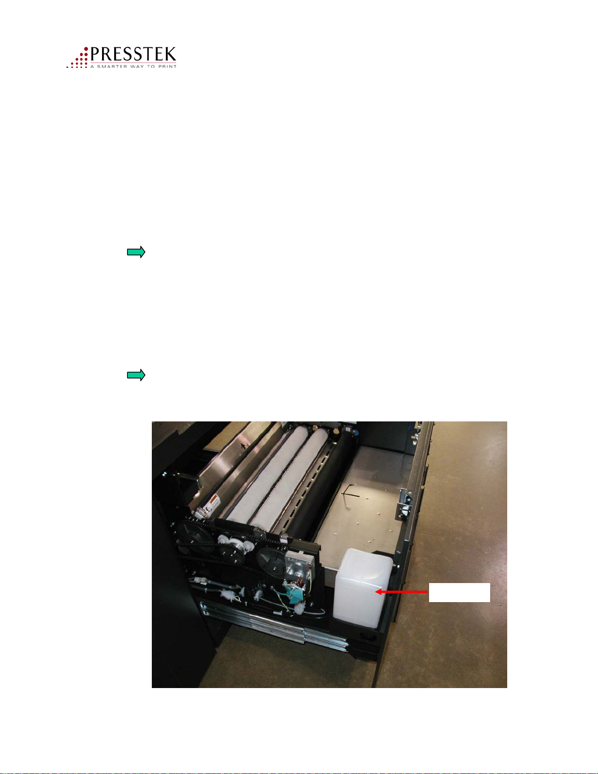
1. Adding water:
Pull open the washer unit. Fill to the level shown by the line in the container.
You may need to replenish water twice daily. Do not overfill.
DO NOT USE DISTILLED WATER. It is not conductive and the water level
sensors will not sense the water level.
Vector FL52AL Operator Manual
Water tank
65
Page 66
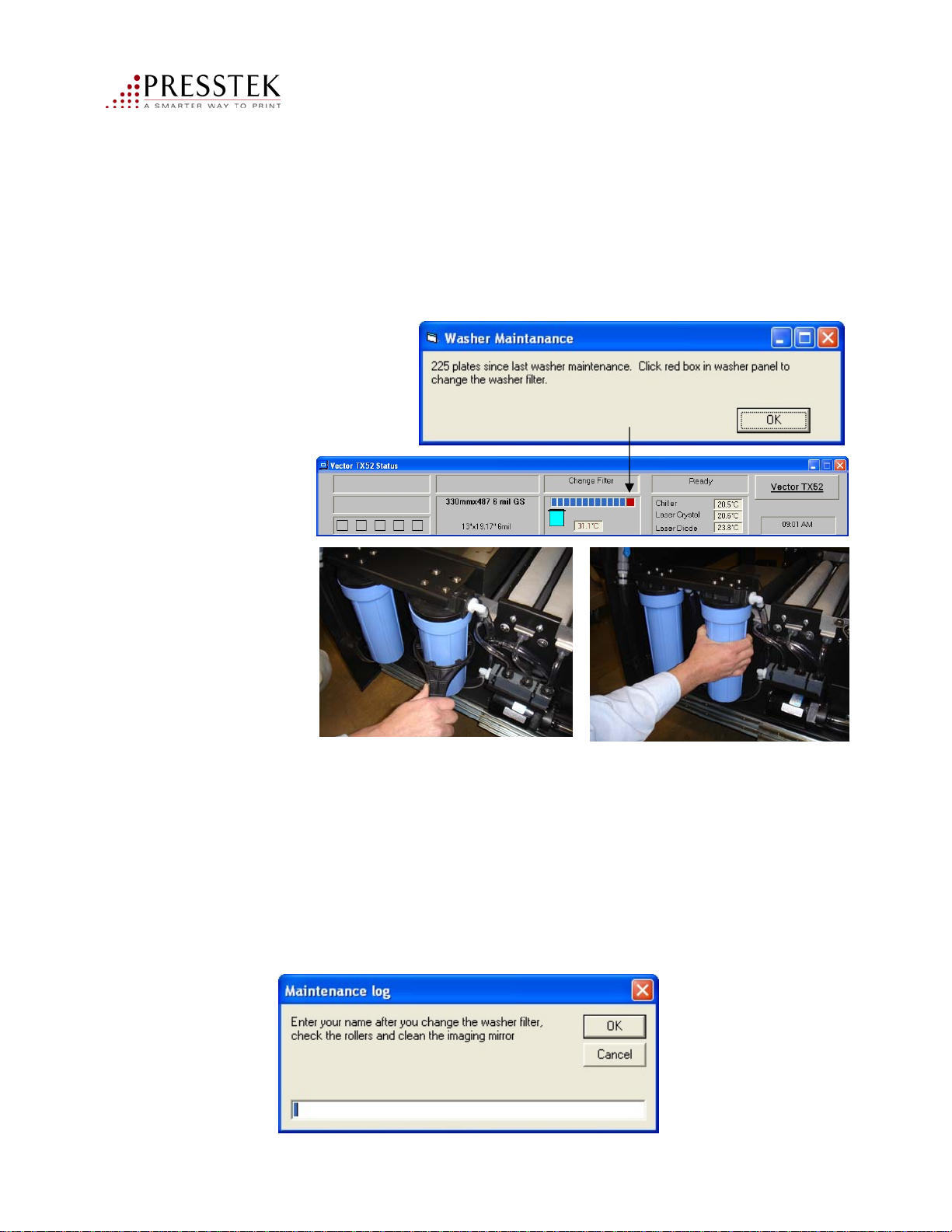
2. Changing the water filters (every 200 plates):
The Washer Maintenance window will appear when it is time to change the filter.
Click OK on this message, then click the red box. You will be prompted to record
the filter change. This will reset the count to 200.
To replace the filter:
a. Pull open the washer unit. Using the supplied tool, loosen the filter housings.
b. Twist the filter housings off by hand.
c. Remove filters and dispose. Replace with filters p/n – VECFILTER-6C.
d. Do not over-tighten fitter housings.
Vector FL52AL Operator Manual
66
Page 67
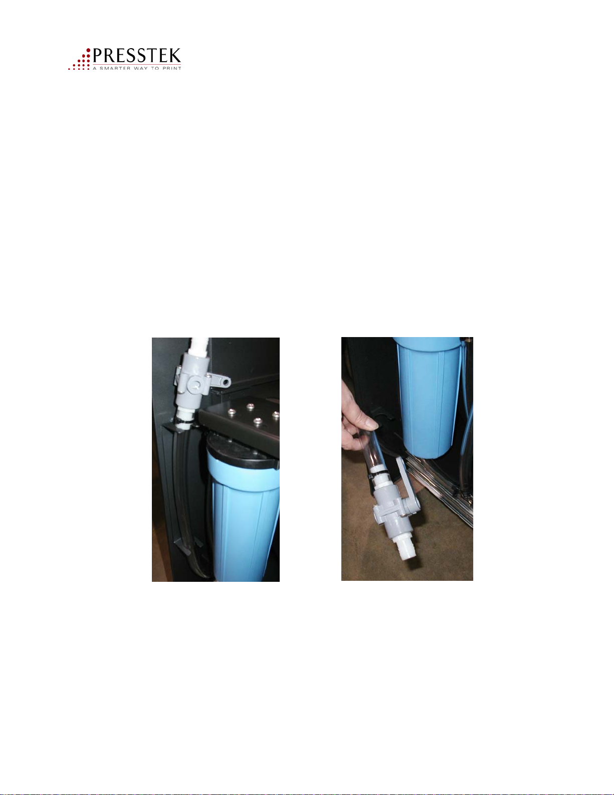
3. Drain the water tank (every 400 plates) or at least once a week
a. Pull open the washer unit. Detach plastic hose and open the valve.
b. Empty wash tank water into a floor drain, bucket or other suitable container.
c. Be sure to close valve when done.
d. Refill the tank. Capacity is approx. 5.5 gallons. Use ordinary tap water,
do not use distilled water.
A Material Safety Data Sheet has been provided which provides information on
waste water analysis and disposal.
Vector FL52AL Operator Manual
67
Page 68
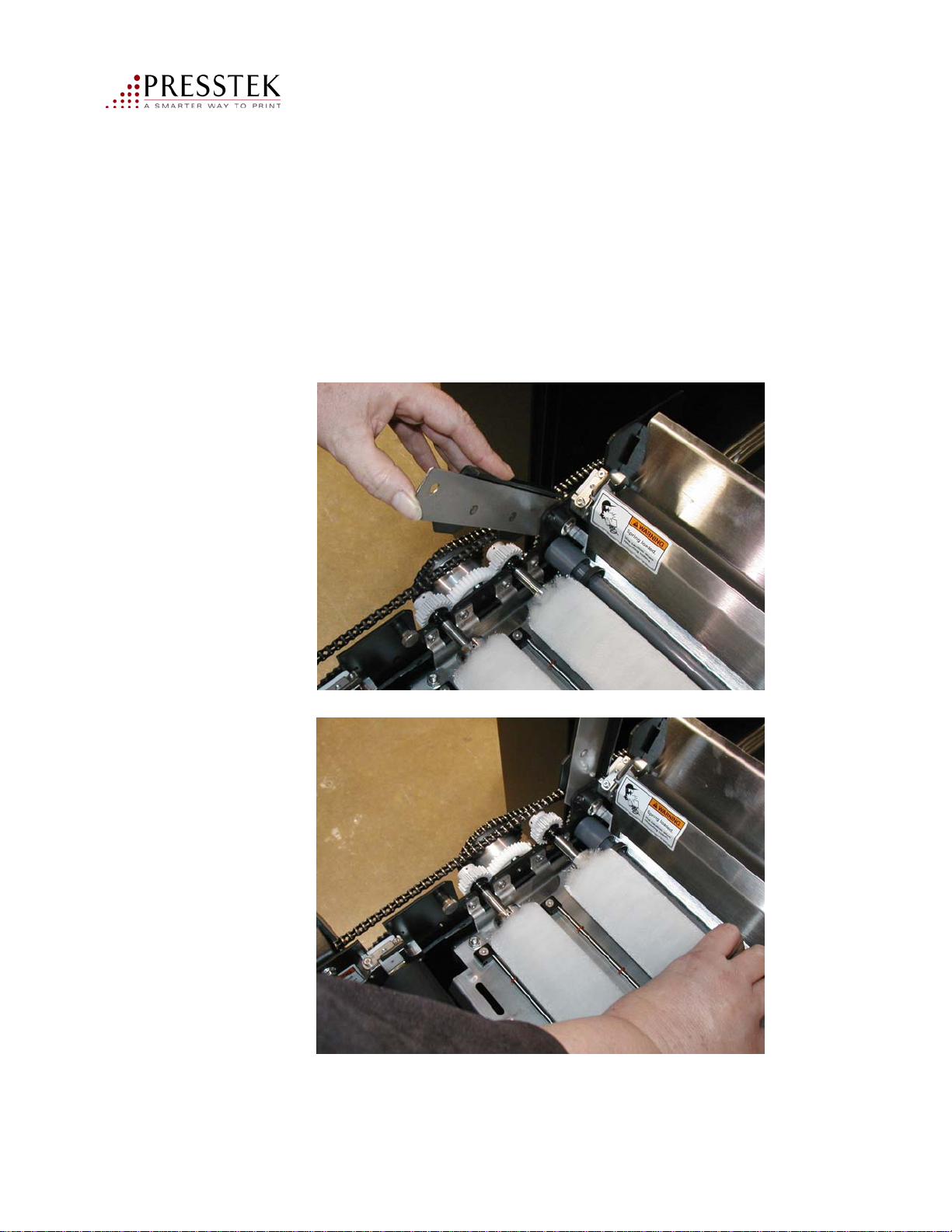
4. Clean the brush rollers (every 400 plates):
a. Lift up latch on each side of the brush rollers.
b. Remove brush rollers from unit. Wash with warm
running water. Replace back into machine.
.
Vector FL52AL Operator Manual
68
Page 69
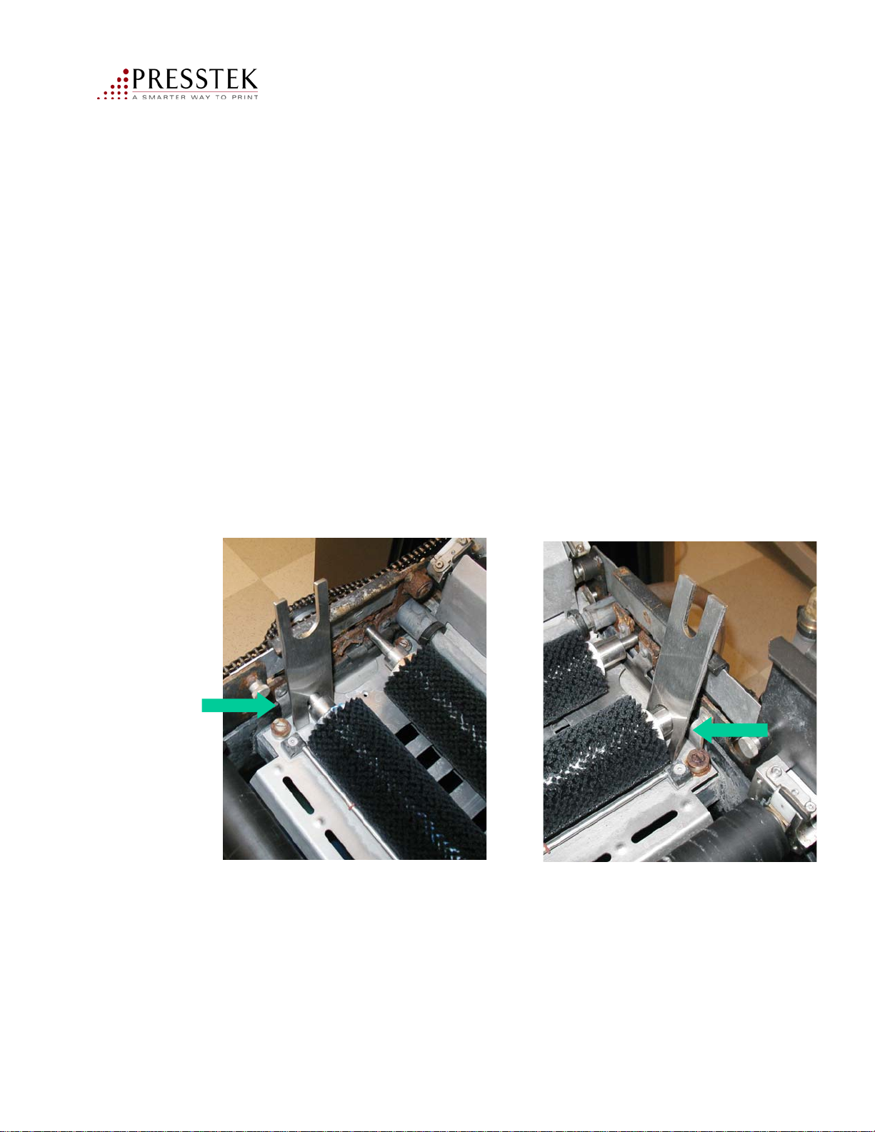
5. Check and adjust washer brush height, if necessary
Brush rollers must be at equal height end to end.
A Washer-Brush Height Adjustment Tool has been provided for this purpose.
(P/N MMM34691)
The tool has 2 U-shaped cut-outs on each end. The smaller cut-out is for the left side
and the larger is used on the right side.
a. Place the brush tool over the shaft of the brush roller and raise or lower
the platen until both feet of the tool touch the platen and the tool remains seated
on the brush shaft.
b. Perform this adjustment to both brush rollers using the platen adjustment
screws located at each end of the brush roller.
Vector FL52AL Operator Manual
Left side
Right side
69
Page 70
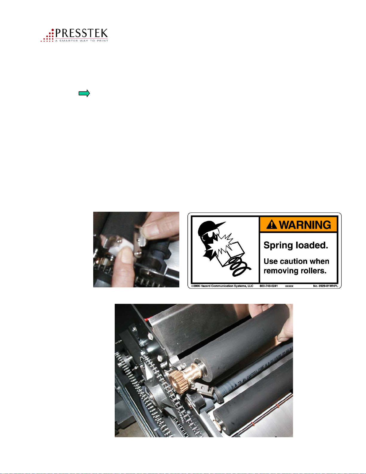
6. Remove and clean the rubber transport rollers:
Observe warning label that rollers are spring loaded.
a. Remove steel plate.
b. Push down white spring block and pull holder to the side
c. Carefully let up on the white spring block. Remove and set aside.
Repeat on other side. See Figure 1.
d. Lift out rollers. Clean with water and alcohol. If there is hard water
buildup, use CLR or Limeaway. Use a clean rage. Rinse thoroughly with water.
e. Re-insert rollers and spring blocks into the Vector FL52. Return steel plate
to its locked position.
Vector FL52AL Operator Manual
Figure 1
70
Page 71
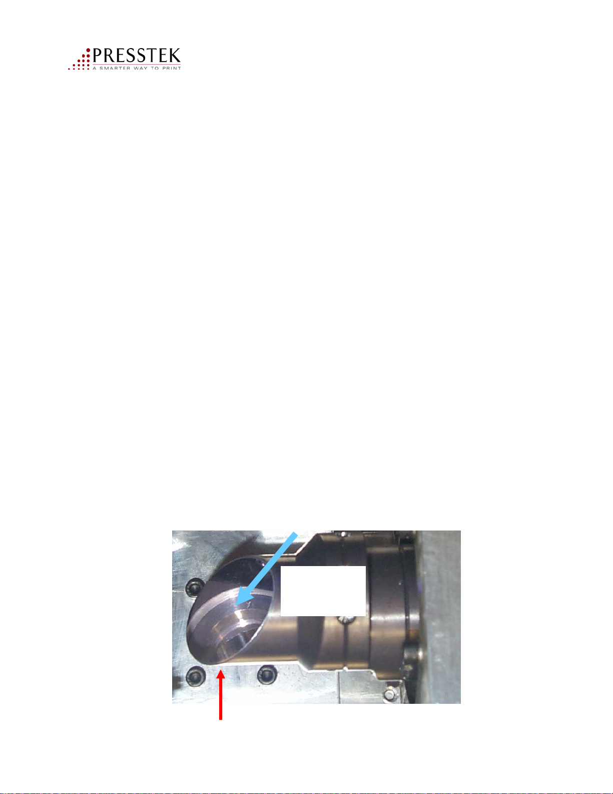
7. Spinner Mirror Cleaning Procedure (every 200 plates)
Tools & Material required:
Lint-free cloth and acetone. Note: read and heed warnings label on container.
No special tools
(Recommend lint-free wipes: TX404 Absorbond Wipers (Synthetic) from
ITW Texwipe at www.texwipe.com).
a. Power down the computer and the Vector FL52.
b. Remove left and right side covers.
c. Remove top cover.
d. Carefully rotate the mirror shaft so that the mirror faces upward.
e. Use lint-free cloth slightly moistened with acetone.
f. Gently clean the mirror with a single downward stroke as shown.
Repeat using a fresh clean area of the lint-free cloth until the mirror is clean.
NOTE: Do not rub in circles.
Do not rub back and forth.
Do not rub hard.
g. Replace the side and top covers and power up the computer and the Vector FL52.
Wipe in single
downward
stroke
Mirror
71
Vector FL52AL Operator Manual
Page 72
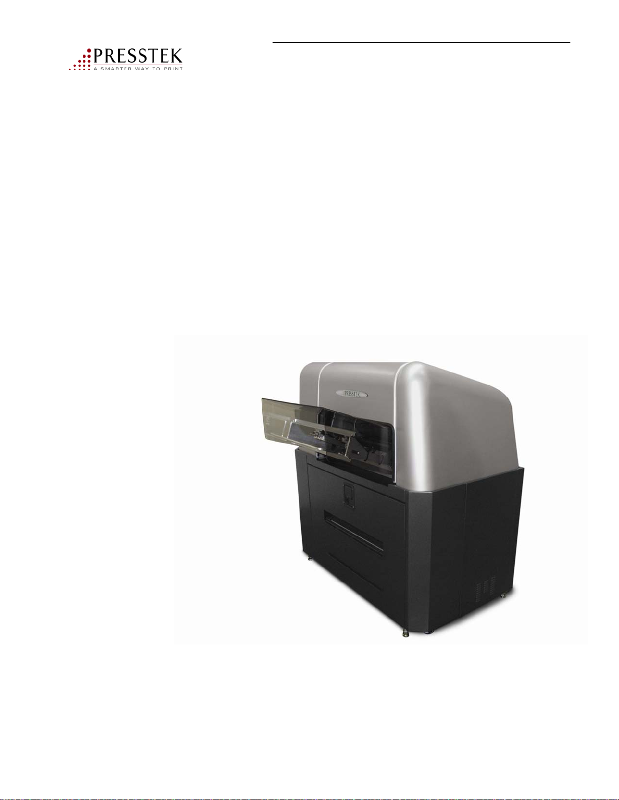
Chapter 5
Troubleshooting
Vector FL52AL Operator Manual
72
Page 73
Troubleshooting
The Vector FL52 platesetter uses proven imaging design, media path and
reliable software. In the unlikely event that a malfunction occurs or you need
to take action before plate making can proceed, you will be alerted in one of
three ways.
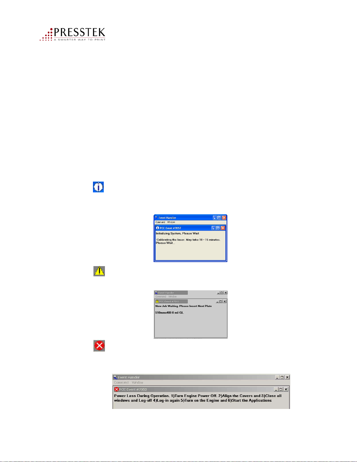
1. Message Handler Information
2. Status Bar Information
3. Device Dialog Errors
There are three categories of messages:
no action is required. The system will automatically resume when the
required conditions are reached. See example below:
– Informational messages let you know that plates are waiting but
– Alert messages let you know that you need to take a certain
action before plate making can proceed. See example below:
– Error messages let you know that you that a malfunction has
occurred as shown below. You need to take a certain action before plate
making can proceed. Please see next page for descriptions.
73
Vector FL52AL Operator Manual
Page 74
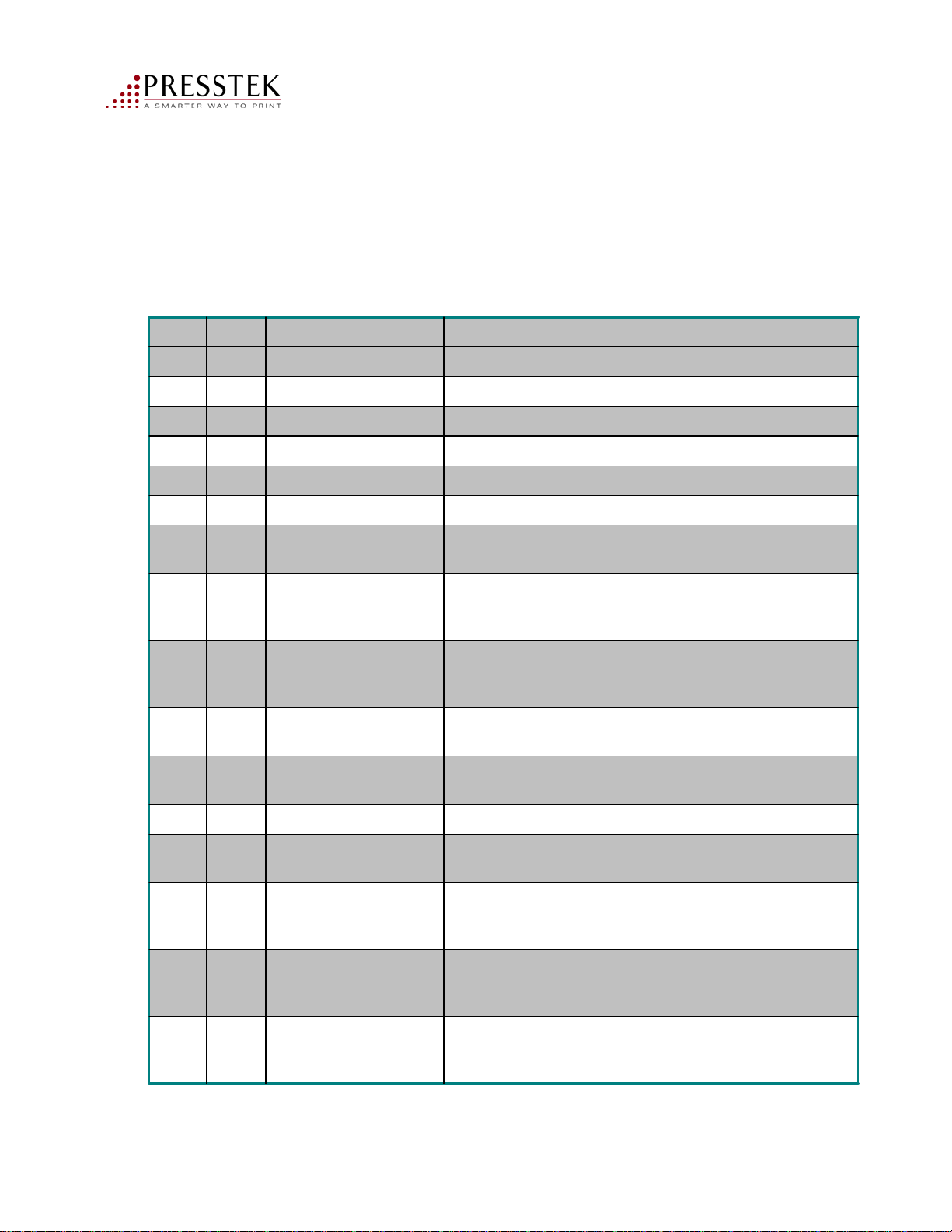
Error Codes/Causes/Recommended Action:
Recommended ActionCauseCodeType
Check the plate size, image size and margins of your plateInvalid Job Information7003Error
Check your plates and re-run the failed jobData Underrun7011Error
Load the required plate Job waiting for plate7013Alert
Turn off the machine, wait 30 seconds, turn on the machineLoss of power7017Error
Close the washer drawerWasher drawer Open7018Alert
Replenish water in the washer Washer Liquid Low7019Alert
Machine malfunction7020Error
7024Info
washer to reach required
temperature
7027Error
or registration lost
during load
Washer Jam7028Error
7034Error
7045Info
7046Alert
Dongle missing or
invalid
Conveyor plate jam7042Error
more components too
cold or too warm)
motor switch not
making contact
Turn off the machine, wait 30 seconds, turn on the machine
If problem recurs, call service
None – machine will resume automaticallyPlate is waiting for the
Check your plate size and load it againWrong plate size loaded
Open the washer drawer and clear all plates in the washer.
Close the washer drawer
Check the back of the computer. Make sure the machine
dongle is secure on the parallel port. Restart the system
Remove your finished plate from the exit trayPlate in washer exit7038Alert
Open the washer drawer, open the conveyor drawer, remove
any plate in the conveyor. Close all drawers
None – machine will resume automaticallyLaser not ready (one or
Align and replace the left cover The left cover is open or
7047Alert
or motor switch not
making contact
Vector FL52AL Operator Manual
Align and replace the right cover The right cover is open
74
Page 75

Recommended ActionCauseCodeType
7048Alert
or laser switch not
making contact
7049Alert
or laser switch not
making contact
7050Error
7052Alert
Laser temperature out
of range
Power loss during
operation
Align and replace the left cover The left cover is open
Align and replace the right cover The right cover is open
Click OK on the error message window. Machine will
resume when laser temperature returns to nominal.
Please close the conveyor drawer (inside the washer drawer)Conveyor drawer open7051Alert
Please restart the CTP and computer:
1. Turn off machine
2. Log off on computer
3. Log on again
4. Turn on machine
5. Start the VectorFL52 software from the start menu
Vector FL52AL Operator Manual
75
Page 76
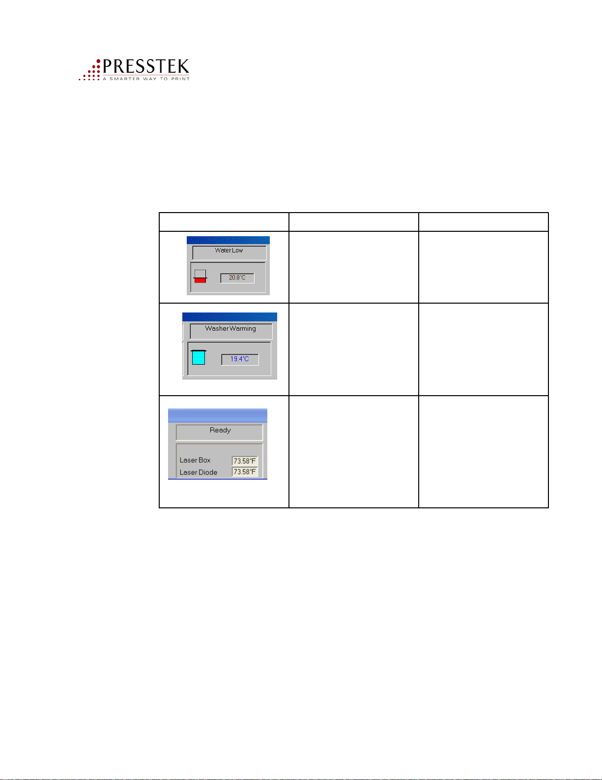
Status Bar Indicators
Icons and text displayed on the status bar indicate status and required
action as follows
Required ActionCauseDisplay
Washer Liquid level is low
Washer water has not
reached the required
temperature
The imaging module is
adjusting one or more of the
components’ temperature.
The temperature display
indicates whether the
component is too warm
(Red), too cold (blue) or in
range (black)
Replenish the washer water
bottle
Wait for the water to warm
up
Wait for the imaging module
to reach the desired state.
Vector FL52AL Operator Manual
76
Page 77

Imaging Dialog Errors
These messages will inform you why a particular job cannot be output to plate.
Required ActionCauseDisplay
Scriptworks Print Buffer
must be at least xxx bytes.
Current Size is yyy
Top Margin xx < Min yy
Image Length xx > Max
Image Width xx > Max
Requested Resolution is not
supported
The PrintersRIP is not
configured properly
The user has entered an
invalid margin. Note the
top margin corresponds to
the gripper margin
The image dimensions
exceed the imageable area
of this plate
supports 2400 DPI output
From the Printers RIP menu select
Configure RIP. Adjust the Printer
Buffer Size. Restart the RIP
Enter a margin value greater than
the specified minimum
•The image may need to be
rotated: Select Cancel to proceed
to the next plate or Disable to stop
the RIP queue. Correct the job at
the desktop
or
•Adjust the margins or select
clipping and click OK to output
the plate with the new parameters
Adjust the resolution in the RIPThe VectorFL52 only
Vector FL52AL Operator Manual
77
Page 78
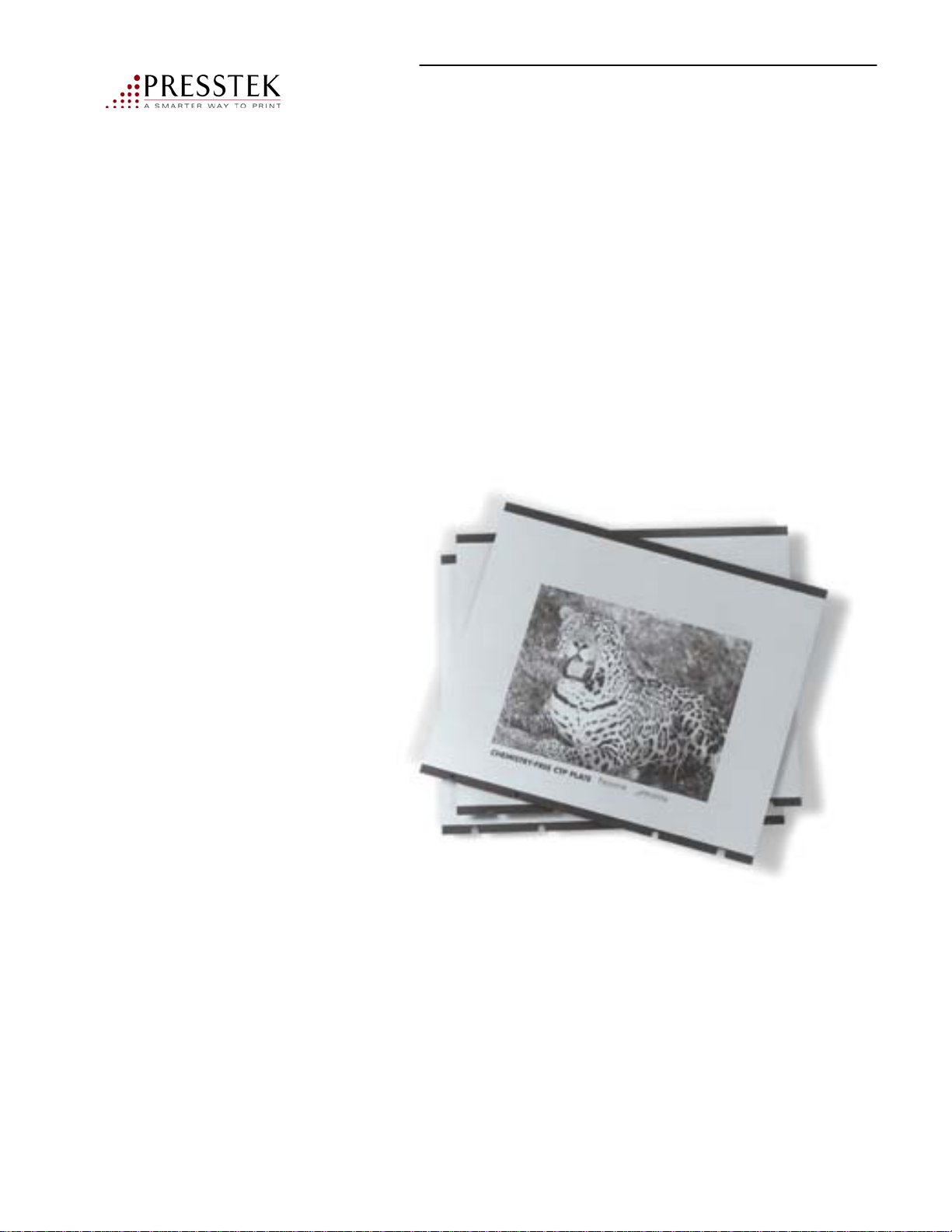
Chapter 6
Freedom Pro Plate
Vector FL52AL Operator Manual
78
Page 79

Characteristics
Freedom Pro is a thermally imaged aluminum printing plate. The top surface is
the ink receptive layer, which is heated by laser energy during imaging. This layer
and some of the water receptive layer below are made water soluble by the heat
from imaging. Subsequent cleaning reveals the water receptive layer, and leaves
the non-imaged print areas on the plate. Because the laser writes the non-image
area of the plate, Freedom is a positive writing plate.
Plate Design
Freedom Pro is composed of layered compounds coated on a grained and
anodized aluminum substrate. The black colored layer is designed to aid in
imaging and serve as the ink receptive surface. The thin film beneath is the nonimage area of the plate.
Ink Receptive Image Area
Thin Film Non-Image Area
Anodized Aluminum Plate
During the imaging process, thermal energy from the laser is absorbed by the black
image layer. Freedom Pro is a sub-ablative plate. There is almost no image visible
on the plate after exposure. The unwanted ink receptive layer is not removed by
the laser, it is washed off in the plate cleaner with heated tap water.
Vector FL52AL Operator Manual
Freedom Pro Thermal Wet Offset Plate
79
Page 80

Basic Properties
Reproduction capability (FL52):
2400 dpi 2% - 98% up to 175 lpi
Average durability of the plates: Up to 25,000 impressions
Available plate thicknesses: .006 in. (.150mm) and .008 in. (.203mm)
The durability of the plate is dependent on the amount of paper debris, roller
condition, amount of spray powder used and condition of the printing press.
Storage
Store plates in a cool, dry and chemically free environment. Temperatures should
not exceed 55-75 F with 30-60% RH. It is best to keep the plates on a flat surface
after removing them from the packaging. This will protect the plates from damage
and/or kinks.
After opening the package, cut and remove the plastic packaging straps from
around the plates. Remember to remove the outside labeling that contains the lot
number information. Keep this information with the plates for reference if needed.
If the plates will be stored before they will be run on press, the recommended
procedure is to flip over the top plate so that coated (image) side is down or cover
the top plate with the slip sheet. This will prevent airborne contaminants from
affecting the plate.
When storing the plates for re-use, apply a dilute storage gum or finisher to the
plate and buff dry with a cloth. This will allow the plate to be stored and re-used at
a later date.
Handling
Plates are punched with conventional punching devices, either prior to or after
imaging. Some computer-to-plate systems have automatic punching devices built
into the imager.
Load the plate onto the imaging device according to the standard procedure
for that device. Save the interleaf paper as it can be used during storage and/or
transportation to the pressroom. Image the plate normally according to the
procedure that has been set up by the imager manufacturer. After imaging,
the plate will require a heated water rinse.
Vector FL52AL Operator Manual
80
Page 81

Cleaning
Freedom Pro requires a water rinse to remove the non-image, ablated material. This
rinse is done with a simple rotating brush cleaning device using ordinary heated tap
water. The plate requires no gumming after cleaning prior to printing. The Vector
FL52AL automatically cleans the plate after imaging. Note: high water hardness
and/or extreme pH levels may affect cleaning performance.
Fountain Solutions
Freedom Pro can be used with virtually all commercially available fountain
solutions. The recommended pH range is between 4.0 - 6.0. Very strong, acidic or
alkaline fountain solutions should be avoided as they may cause damage to the nonimage area of the plate. The conductivity of the fountain solution should be above
1300 ms to insure the best printing results. The concentration of the fountain
solutions should be based on the manufacturer’s recommendation, but it may be
necessary to optimize them to the press, paper and ink being used. Alcohol and
alcohol substitutes may be used with Freedom Pro.
Recommended fountain solutions and mixtures
ABDick 4-1185
oz/gal
3 oz/galPrisco 2451
MixtureIPA substituteMixtureFountain
R
IPA
%
N/AN/AN/A6-8oz/galPresstek ThermoFount-1
N/AN/AN/A4 oz/galABDick 38773
N/AN/AN/A4 oz/galABDick Formula 300
2%N/AN/A2.5
NA3 oz/galAnchor ARS-JP4 oz/galAnchor Emerald JRZ
NA2 oz/galPrisco Alkaless
10%N/AN/A3 ozPrisco 2451
NA1 oz/galVarn Jetwet3 oz/galVarn Crystal 2500
10%N/AN/A3%Varn Total
8%N/AN/A4%VarnSupreme
6%N/AN/A4%Varn Fount 2000
10%N/AN/A6%Combifix
These fountain solutions and mixtures are representative of a small portion of fountain
solutions that will work with Freedom Pro.
Vector FL52AL Operator Manual
81
Page 82

Inks
Freedom Pro can be used with all commercially available inks including UV. In
rare instances, there may be an ink/fountain solution incompatibility, which will
require the changing of either the ink or fountain solution.
Press Settings
The press should be set to the press manufacturer’s recommendations. There are
no additional adjustments that are required for the printing Freedom Pro plates.
Excessive ink form roller settings will cause scumming in the non-image area of
the plate. This is due to the forcing of the ink into the non-image area and not
allowing the fountain solution to repel the ink.
Over packing of the blanket can cause premature wear of the non-image layer of
the plate, resulting in an unwanted image.
Proper roller maintenance is required to insure that unwanted debris will not
come in contact with the non-image surface of the plate. Debris that is trapped in
the roller surface, will cause scratches during printing. Excessive roller pressure
may also cause premature plate wear. Proper roller maintenance to eliminate
these contaminants (paper dust, calcium and dried ink) will increase the durability
of the plate.
Make Ready
Mount the imaged plates on the press. Freedom Pro can be used in manual,
semi-automatic and fully automatic plate loaders. Make sure that the loaders are
free of dried ink or other debris, as this will cause scratches. Freedom Pro rolls
up quickly with no pre-dampening required
Plate Cleaning during printing
Freedom Pro may require cleaning during printing. There are several excellent
plate cleaners that can be used with Freedom Pro. Test any plate cleaners in a
non-printing area of the plate prior to use on the entire plate. Below are several
recommended cleaners:
Allied PC93
Enco FPC
Fuji Plate Scratch remover
Varn Quick Blue/True Blue
Plate-Sav-UR
Vector FL52AL Operator Manual
82
Page 83

Additions & Deletions
Deleting an image from the plate surface is done using several types of deletion
pens. A preserver such as gum must be used after deleting an image or that area
will accept ink. The deleted area must be desensitized. Listed are several
deletion pens that will work with the Freedom Pro plate.
Presstek’s AnthemPro Image Deletion Pen P/N 136-1 available through
https://shop.presstek.com
Allied NNP
Base Line
Kodak Aqua
KPG 229
Nikken Etching
Vector FL52AL Operator Manual
83
Page 84
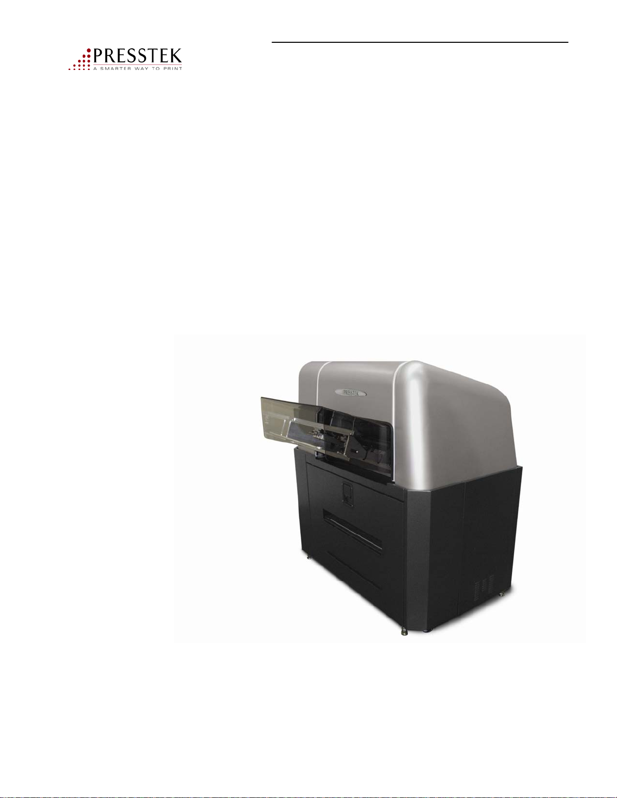
Appendix A
Supplies (Freedom Pro Plates, Filters, etc).
Customer Support: 1-800-422-3616
Vector FL52AL Operator Manual
84
Page 85
Specifications
and Supplies
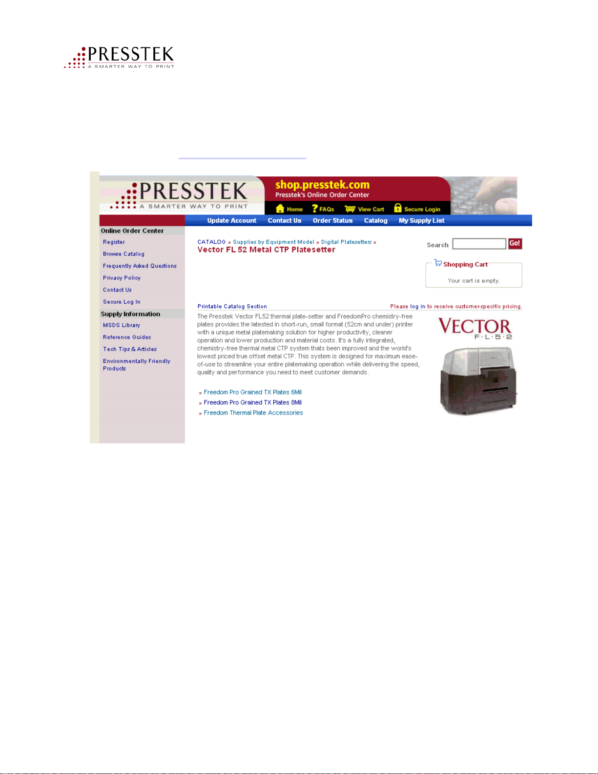
Visit us on-line at https://shop.presstek.com for a complete listing of plates available
for your Vector FL52AL.
Plate Punch
PTEK-2330-AB 220/425 mm Combo Plate Punch Each
Filters
VECFILTER-6C Washer Unit Filter Kit (contains 6) 6/Kit
Plates / Shop On-Line
Visit us on-line at https://shop.presstek.com 24/7 for plates, supplies and
pressroom necessities. Browse our conveniently organized catalog and place orders.
At https://shop.presstek.com you can access customer-specific pricing, view current
product promotions, build a custom “my supply list”, track order status and
shipments and much more!
Specifications are subject to change without notice.
Vector FL52AL Operator Manual
85
 Loading...