

Pressol Pneumatic Oilpump 3:1 Operating Instructions Manual
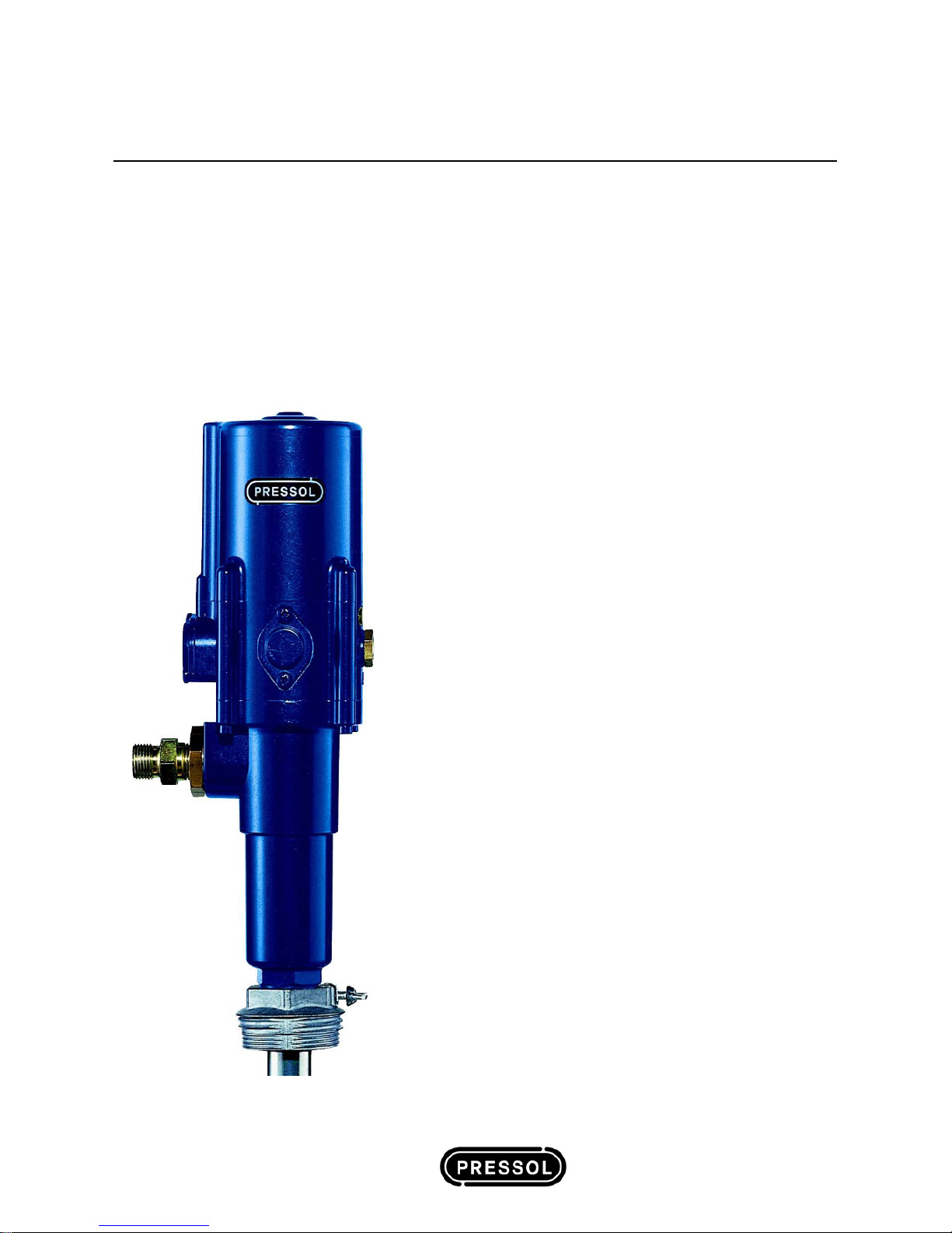
Pneumatic Oilpump 3:1
Operating Instructions
Contents:
1. General Information
1.1 Usage Stipulations
1.2 Construction & Functional Description
1.3 Technical Data
1.4 Application Range
1.5 Operational Area Requirements
2. General Safety Advice
2.1 Safe Working Advice
2.2 Risks when Working with the Oil Pump
3. Assembly
3.1 Barrel- and Tank Mounting
3.2 Wall Mounting
4. Preparing for Operation
4.1 Venting the Pump and Installation
5. Operation
5.1 Changing a Barrel
6. Maintenance
7. Accessories
8. Fault Finding
9. Repairs/Service
10. EC Declaration of Conformity
11. Exploded view
03 593 A 407 GB
Pneumatic Oil Pump 3:1 Operating Instructions
Explanation of Safety Advice
The safety advice provided in these operating instructions is categorised according to different
danger levels. The different danger levels are identified within the instructions by the following
symbols and identifying words:
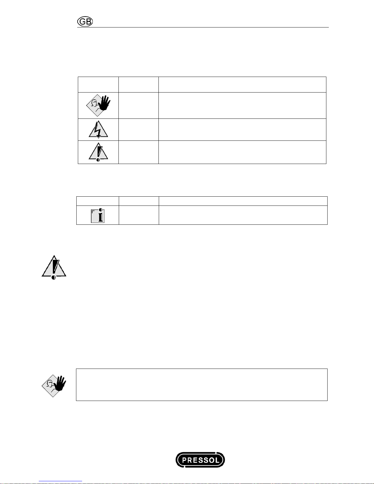
Symbol Indicates
Result if the safety requirements are not observed or
applied
Danger Death or very serious injury
Warning Possible death or serious injury
Caution Possible slight or not serious injury or material damage
Tab. 1-1: Safety Advice Classification according to Danger Type and Severity
In addition, another symbol is used to indicate general tips about using the product.
Symbol Indicates Meaning
Note Background information or tips about how to use the product
Tab. 1-2: General Information
If the oil pump is incorrectly installed, or used for a purpose
other than that originally intended for, it can result in personal
injury or damage to equipment!
Before starting to use the oil pump, read through these operating instructions carefully and
completely.
1. General Information
1.1 Usage Stipulations
• This oil pump can be used to deliver lubricating oil and similar neutral fluids.
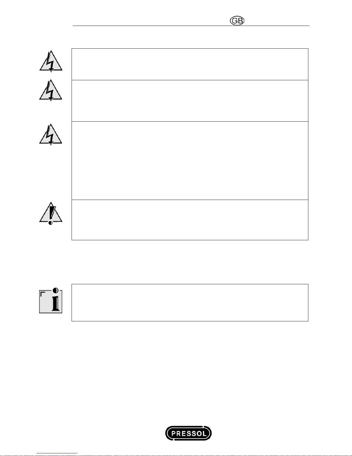
Danger!
Never use it to deliver explosive fluids such as petrol, or other fluids with similar
flashpoints!
• To ensure that usage stipulations are met, read through the operating instructions completely
before using the pump and observe all stipulations.
2 Status 31.01.2008

Operating Instructions Pneumatic Oil Pump 3:1
• Any departure from the usage stipulations (other fluid media, use of force) or user
modifications (changes, use of non-original parts) can be dangerous and are considered as
non-stipulated usage.
• The user is liable for any damage resulting from non-stipulated use.
• Before commencing any repair or maintenance work, release the pressure from the installation.
• Repairs and maintenance are only to be carried out by qualified specialists.
• Only original replacement parts are to be used for any repairs, otherwise the warranty will be
invalidated.
1.2 Construction & Functional Description
• The oil pump can be fitted with a variety of PRESSOL accessories.
• The Pump casing is manufactured from die-cast zinc with a hardened stainless steel piston rod
and high quality durable synthetic control components.
• The polyurethane or Buna N o-rings and washers are designed to meet the ope rating
requirements of the pump.
1.3 Technical Data
Typ 3:1
Year of Production See Identification Plate
Ratio 3:1
Max. Air Pressure bar 10
Recommended Air Pressure bar 8
Min. Air Pressure bar 2
Max. Oil Pressure bar 30
Max. Delivery Performance* L / min 20
Max. Air Consumption. L / min 450
Air Inlet G ¼” i
Oil Outlet G ½” a
Piston Diameter mm 80
Piston Stroke mm 44
Motor Displacement cm³ 220
Pump Displacement cm³ 70
Max. Sound Level at 2 m Db (A) 78
Wight kg 7,2
* under free discharge
Tab. 1-3: Technical Data
Status 31.01.2008 3

Pneumatic Oil Pump 3:1 Operating Instructions
1.4 Recommended Applications
This pump was developed for pumping diesel, motor, and hydraulic oil as well as low-viscosity and
selflubricating mediums. The pump is recommendable for use in pipe systems together with a
hose reel. Evenwith a 15 m hose, delivery meter and anti-drip nozzle, the pump still has a very
high delivery performance. The delivery performance is dependent uopn the viscosity of the oil,
the temperature as well as the length and the cross-section of the piping. The pump will also
operate in non-vertical installations.
1.5 Operational Area Requirements
The operator of such an installation is, according to § 19i WHG (Germany) responsible for
continuous monitoring to ensure compliance with the above stated requirements at the installation.
The oil pump is intended for use within a building. The installation area must be selected such that
correct operation is ensured.
To avoid unnecessary damage and to prolong the life expectancy of the pump we recommend
that an air line combination filter, regulator and lubricator is utilised to ensure that the compressed
air supply is not contaminated and is regulated at the recommended pressure.
New installation lines should be cleaned to avoid any residual metal filings damaging individual
components within the pump. When changing containers protect the suction tube properly to
make sure that the suction tube will not be contaminated by dirt particles, such as metal parts,
splinters etc. which will additionally contaminate the lubricant in a new container.
To make service and maintaining work easier we recommend the installation of a lever ball valve
placed between the oil connecting hose and the fixed oil distribution pipe work.
Um Reparaturen oder Servicearbeiten leichter durchführen zu können, empfehlen wir einen
Kugelhahn zwischen Druckschlauch und Öldruckleitung zu montieren.
2. General Safety Advice
2.1 Safe Working Advice
• The oil pump has been designed and manufactured according to the health and safety
requirements of the relevant EC guidelines.
• Nevertheless, there can still be risks if the product is not set up or operated as stipulated.
• Therefore, before using the oil pump, read these operating instructions and pass them on to
other users of the pump.
• When operating the oil pump, the local safety and accident prevention rules and regulations
always apply, as well as the safety advice in the operating instructions.
• Only approved PRESSOL maintenance personnel should open or repair pumps within the
guarantee period.
WARNING! The compressed air line must be disconnected and the discharge pistol actuated to
ensure so the pump is depressurised before the pump unit is opened or inspected. For safety
reasons the compressed air line should be disconnected when the pump is not in use otherwi se
the pump will remain pressurised.
4 Status 31.01.2008
Operating Instructions Pneumatic Oil Pump 3:1
2.2 Risks when Working with the Oil Pump
Warning!
Never work on a pump that is running!
Mount or remove attachments and accessories only when the pump is switched off.
Warning!
Do not pump contaminated fluids!
Take special care to ensure that there is no contaminant in the fluid to be pumped.
Install a strainer on the suction pipe.
Warning!
Damaged attachments and accessories can lead to personal injury and material damage!
Suction and pressure pipes must not be kinked, twisted or stretched.
The pressure-side installation of an overflow valve is recommended (see accessorie s).
Attachments and accessories must be checked for wear, splits or other damage at all times.
Damaged attachments and accessories must be replaced immediately.
With reference to the period of use, please note the details in ZH 1/A45.4.2 or DIN 20066
Part 5.3.2.
Caution!
Spilled fuel can result in environmental damage
Local and country rules and regulations relating to domestic water supplies and fuel storage
must be obeyed.
3. Assembly
• The oilpump can be used for oil supply out of original drums or out of oil storage tanks.
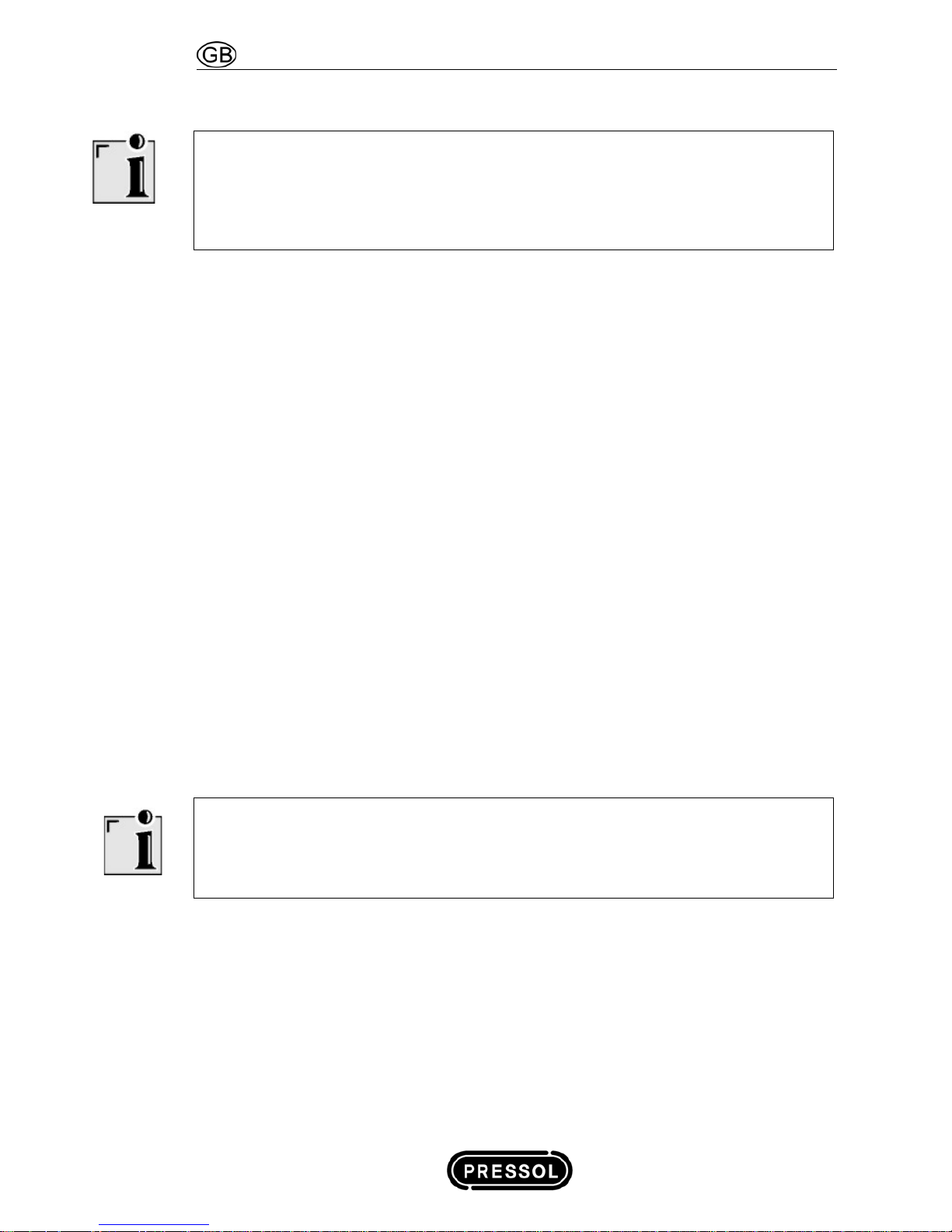
Note
An upward installation of the suction line is recommended according to European regulation.
Consider before assembly the height of the container used and in case of necessity the use of an
oil container storage unit..
3.1 Barrel- and Tank Mounting
• Fix pump and suction tube using the G 2“ drum retention adapter on the container or on the
storage tank.
• Connect the discharge hose to the pump connecting adapter G ½“.
• Connect the discharge valve or the manual flow meter to the discharge hose.
Status 31.01.2008 5
Pneumatic Oil Pump 3:1 Operating Instructions
3.2 Wall Mounting
Note
When installing the 3:1 oil pump in connection with long distribution lines we recommend the use
of a foot valve
To avoid possible overpressures in the pump we recommend in any case the installation of a foot
valve with an overpressure releasing drill hole (art.no. 03337).
• For fixation of the oil pump we require 2 screws with a diameter of 10 or 12 mm (not included in
the product packageChoose screws corresponding to the wall material, on which the pump
shall be mounted.
• Take care for a stabil wall mounting of the pump. Take care for a protected mounting location,
protecting i.e. against splash water,
• Please mount the calibratable pump for a trouble-free operation of the integral air elimator in an
upright position, only.
• Fix suction tube using the G 2“ drum retention adapter on the container or on the storage tank.
• Connect suction tube and pump with suction hose (hose connection G ¾“)
• The air- and oil back-flow tube of the calibratable pump version shall be lead back into the
container or tank utilizing the drilled hole in the drum adapter.
• Connect oil pump with control valve or manual flow meter and oil discharge pipe work with a
discharge hose.
• Installation material for discharge pipe work
• Length of discharge pipe work up to 15 m: Pipe work tube DN 20 (R ¾“) DIN 2448 or
bigger; St 37 acc. to DIN 1629.
• Length of discharge pipe work exceeding 15 m: Pipe work tube DN 32 (R 1 ¼“) DIN 2448
or bigger; St 37 acc. to DIN 1629.
• Overflow valve (see accessories).
• Lever ball valve (see accessories).
Note
Pay attention to a correct installation ad to a accurate connection of the accessories with the
pump
Use suitable sealing material in any case. (i.e. Teflon-tape).
• The pump is now ready for operation.
6 Status 31.01.2008
Operating Instructions Pneumatic Oil Pump 3:1
4. Preparing for Operation
4.1 Venting the Pump and Installation
• Connect Pump with compressed air ( 6 bar recommended)
• Open the farthest control valve of the installation supported by a oil collecting tray until oil will
be discharged completely air-less.
• Repeat this procedure on any point of discharge of the installation.
5. Operation
Note
To ensure that the tank can be completely emptied, the suction hose must reach to the bottom of
the tank.
Caution!
Never operate the pump without delivery fluid. There is a danger of your oil pump being damaged
if operated dry.
Caution!
Shut-off the compressed air line, when the oil supply system is not needed for a longer time in
any case.
• Start the pump with compressed air, the oil supply system is ready for operation.
• The pump switches on and starts to discharge when opening the control valve.
• When closing the control valve the pressure in the oil system will increase forcing the pump to
come to a stillstand.
5.1 Changing a Barrel
• You can avoid contamination by inserting the suction line directly into the new oil container.
6. Maintenance
The muffler and air inlet filter should be cleaned regularly to maintain the trouble free performance
of the pump. If an air line lubricator has not been installed frequently lubricate the pump by
inserting 2 to 3 drops of quality oil through the air inlet connector at regular intervals.
The oil pump is very easy to maintain and service.
Due to the operator responsibilities according to § 19i WHG (German rules), the following
components must be regularly checked and replaced as necessary, to minimise the possibility of
environmental or equipment damage, or personal injury:
Status 31.01.2008 7
Pneumatic Oil Pump 3:1 Operating Instructions
• Pump housing
• Delivery hose
• Nozzle valve
• Connection lines
7. Accessories
• Dual-Suction pipe, 2 m, No. 19 511
• Suction pipe, for oil, 2 m, G ¾ “ i, G ¾“ o, No. 19 512
• Suction tube, G ¾“ i, G 2“ o, SRL 860, for 200/220 l container, No. 19 522
• Suction tube, G ¾“ i, G 2“ o, SRL 860, for 200/220 l container, with foot valve, No. 19 523
• Suction tube, G ¾“ i, G 2“ o, SRL 1600, for tank mounting, with foot valve, No. 19 523 001
• Conversion set, SRL 860, for 200/220 l container, No. 19 513 950
• Conversion set, SRL 1600, for tank mounting, No. 19 513 952
• Conversion set, SRL 1600, for tank mounting, 90° connector for connecting to Pneumatic-
Pump, No. 19 513 954
• Suction tube, G ¾“ i, G 2“ o, SRL 2100, for tank mounting, with foot valve, No. 19 523 954
• Wall maounting bracket, No. 19 521
• Maintenance unit, No. 20 218 950
• Coiled hose 5 m, No. 20 185
• Lever ball valve G ¾“ i - G ¾“ i, No. 19 763
• Lever Ball valve G ¾“ i - G ¾“ i, No. 19 762
• Discharge hose 0,5 m G½" i - G½" i, No. 19 580 001
• Foot valve G ¾“ i, No 03 337
• Ischarge hose 1,5 m G½" i - G½" i, No. 19 580
• Overflow valve 16 bar, No. 19 648
• Overflow valve 20 bar, No. 19 506
Note
Only with original-PRESSOL spare parts is perfect operation of your oil pump guaranteed! To avoid
faulty operation and danger, please use only original spare parts.
8 Status 31.01.2008

Operating Instructions Pneumatic Oil Pump 3:1
8. Fault Finding
Fault
Cause
Solution
The air motor runs slowly or not
at all..
The air pressure is too low. Regulate the air supply at a minimum
pressure of 3 bar.
The muffler (pos. 20) or the
filter (pos. 11) is obstructed
or dirty.
Clean the muffler and filter.
The air motor is running but the
pump is operating too slow or
not at all.
Leak in the suction pipe. Repair the hole.
Air in the delivery pipe. Remove the air bay:
a) Pressing the discharge pistol after
removing the anti-drip-nozzle.
b) Slightly opening the delivery pipe
immediately behind the pump.
Oil is too cold. Only use oil with a temperature over
15
o
C.
Friction loss in the delivery
hose.
Choose (as far as possible) large
cross sections and short pipe
distances. Place the pump in a
central position.
The air motor is running but no
pressure is generated.
The o-rings, washers or
valves of the pump are
damaged or dirty.
Clean or replace the relevant
components.
Air escapes from the muffler
when the pump is not operating.
The plunger (pos. 5) is
damaged.
Replace the plunger.
The o-rings or the
distributor seal (pos. 19.6)
are damaged.
Replace the components utilising the
complete repair kit.
Article number 72097
Tab. 8-1: Fault Finding
If the solutions given in Tab. 9-1 for solving faults do not solve the problem, please contact our
customer service (Address, See Chap. 10).
9. Repairs/Service
The oil pump was developed and produced according to the highest quality standards.
Should a problem develop, despite all quality controls, please contact our customer service:
Customer Service/Repair Department
PRESSOL Schmiergeräte GmbH
Tel. +49 911 32 441-35 • Fax +49 911 32 441-65 • export@pressol.com
Status 31.01.2008 9
 Loading...