

Pressol 19 060, 19 062, 19 061 Operating Instructions Manual
Operating Instructions
Diaphragm Pumps
19 060
19 061
19 062
81 555 932 A401 GB

GB
Operating Instructions Diaphragm Pumps
Pressol Schmiergeräte GmbH
This documentation is exclusively intended for the operating company and their sta.
Without our written consent, the content of this documentation (texts, gures, drawings, charts,
diagrams etc. ), may not be duplicated or distributed, neither in full or in part, utilized for the purpose of
competition or passed on/made availabe to third parties.
Pressol Schmiergeräte GmbH
Parkstraße 7
93167 Falkenstein | Germany
Phone: +49 9462 17-0
Fax: +49 9462 17-208
info@pressol.com
www.pressol.com
Operating instructions translation
Date of issue: 10/2017
We reserve the right to make design and product modications, which serve to improve the product.
Table of Contents
1. Identication Code ___________________________________________________________________ 3
2. Technical Data ______________________________________________________________________4
3. General Notes ______________________________________________________________________12
4. Operating Principle _________________________________________________________________13
5. Pneumatic Connection _______________________________________________________________14
6. Installation and Use Instruction ________________________________________________________ 14
6.1 Transport _________________________________________________________________________14
6.2 Intended conditions of use ___________________________________________________________14
6.3 Installation ________________________________________________________________________14
6.4 Start Up ___________________________________________________________________________ 16
6.5 Use_______________________________________________________________________________17
6.6 Stop ______________________________________________________________________________ 17
7. Maintenance _______________________________________________________________________17
7.1 Recommendations __________________________________________________________________17
7.2 Disassembly _______________________________________________________________________ 18
7.3 Inspection _________________________________________________________________________ 19
8. Safety Risks ________________________________________________________________________19
8.1 Operations for Installation and Start Up _________________________________________________22
8.2 Operations for Use and Maintenance ___________________________________________________22
8.3 Operations for Repair ________________________________________________________________22
8.4 Disposal ___________________________________________________________________________22
9. Troubleshooting and Possible Causes ___________________________________________________23
2
Operating Instructions Diaphragm Pumps
1. IDENTIFICATION CODE
GB
Pump
Model
19 060
19 061
19 062
Each pump is supplied with the serial and model abbreviation and the serial number on the rating plate, applied onto the support side. Check this data upon receiving the goods. Any discrepancy between
the order and the delivery must be communicated immediately. In order to be able to trace data and
information, the abbreviation, model and serial number of the pump must be quoted in all correspondence.
SERIENNUMMER
Pump
Body
P - PP H - HYTREL T - PTFE T - PTFE P - PP V - FPM 1 - BSP
MODELL
MODEL
Air
Diaphragm
g
Fluid
Diaphragm
code: P065KCMTTKV1Serial No. : P0311 Year: 04/2012
II 3/3 GD c IIB T135°C
Balls Ball
Seats
O-ring Connection Version
HERSTELLUNGSJAHR
Atex Zone 1
x
THREATED
YEAR OF MANUFACTURE
f
f
SERIAL NUMBER
g
ATEX ZERTIFIKATION
ATEX CERTIFICATION
CERT. ZONE 2 II 3/3 GD c IIB T 135°C
CERT. ZONE 2 II 2/2 GD c IIB T 135°C
3

GB
Operating Instructions Diaphragm Pumps
2. TECHNICAL DATA
19 060 A B C D E H Q S T Weight / KgMin/Max
Temp.
223 156 233 110 110 185 59 7 27 4 -4°C/65°C
4

Operating Instructions Diaphragm Pumps
Position Material Description Q. for Pump
1 PP + VTR Central half block 2
1 PP + CF Central half block 2
2 POM-c Pneumatic Exchanger 1
3 AISI 304 Shaft 1
3a NBR Shaft-ring 1
5 STEEL Bellville washer 2
6 ALUMINIUM Air side cap 2
7a Hytrel Air diaphragm 2
7a Santoprene Air diaphragm 2
7b PTFE Fluid diaphragm 2
8 PP + VTR Fluid side cap 2
8 ECTFE Fluid side cap 2
8 PP + CF Fluid side cap 2
8 ALUMINIUM Fluid side cap 2
8 AISI 316 Fluid side cap 3
9 PP Stopper central half block 1
10 FELT Silencer 1
11 PP + VTR Pump casing 2
11 PVDF + CF Pump casing 2
11 PP + CF Pump casing 2
11 ALUMINIUM Pump casing 2
11 AISI 316 Pump casing 2
11 AISI 316 POLISHED Pump casing 2
12 PP + VTR Upper / lower manifold 2
12 PVDF + CF Upper / lower manifold 2
12 PP + CF Upper / lower manifold 2
12 ALUMINIUM Upper / lower manifold 2
12 AISI 316 Upper / lower manifold 2
12 AISI 316 POLISHED Upper / lower manifold 2
13 PP + VTR Ball cage guide 4
13 ECTFE Ball cage guide 4
14 PTFE Ball 4
14 AISI 316 Ball 4
14 EPDM Ball 4
14 NBR Ball 4
15a PP Ball seat with o-ring or gasket Nº 41 4
15a PVDF Ball seat with o-ring or gasket Nº 41 4
15b UHMW HDPE Ball seat 4
15b ALUMINIUM Ball seat 4
15b AISI 304 Ball seat 4
19 AISI 304 Screw manifold 8
19b AISI 304 Nuts collector 8
21 AISI 304 Screw casing 12
21a AISI 304 Washers 20
21b AISI 304 Nuts 16
22 AISI 304 Screw central half block 4
22a AISI 305 Washers central half block 4
26 NBR O-ring 2
28 NBR O-ring 1
30 NBR O-ring 4
32 NBR O-ring upper 4
GB
5

GB
Operating Instructions Diaphragm Pumps
Position Material Description Q. for Pump
32 FPM O-ring upper 4
32 EPDM O-ring upper 4
32 PTFE Gasket upper 4
33 NBR O-ring lower 4
33 FPM O-ring lower 4
33 PTFE Gasket lower 4
33 EPDM O-ring lower 4
41 NBR Internal O-ring seat 4
41 FPM Internal O-ring seat 4
41 PTFE Internal gasket seat 4
41 EPDM Internal O-ring 4
46* AISI 304 Reinforcing ring manifold 2
47 PP Stroke Spacer 2
51 ALUMINIUM Air connection with O-ring 1
*ACCESSOIRES
6
Operating Instructions Diaphragm Pumps
GB
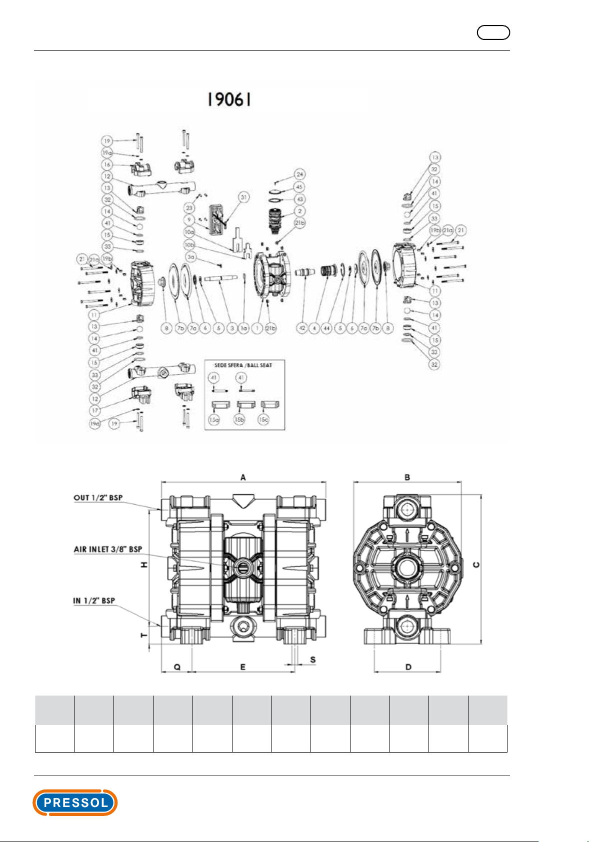
19 061 A B C D E H Q S T Weight / KgMin/Max
Temp.
265 175 245 108 175 189 50 9 29 6,5 -4°C/65°C
7

GB
Operating Instructions Diaphragm Pumps
Position Material Description Q. for Pump
1 PP Central block 1
1 PP + CF Central block 1
1a NBR O-ring 1
2 POM-c Pneumatic-Exchanger 1
3 AISI Shaft 1
3a NBR O-ring 1
4 POM-c Diaphragm with O-ring 1
5 STEEL Bellville washer 2
6 ALUMINIUM Air side cap 2
7a Hytrel Air diaphragm 2
7a Santoprene Air diaphragm 2
7a EPDM Air diaphragm 2
7a NBR Air diaphragm 2
7b PTFE Fluid diaphragm 2
8 PP + VTR Fluid side cap 2
8 ECTFE Fluid side cap 2
8 PP+CF Fluid side cap 2
8 ALUMINIUM Fluid side cap 2
8 AISI 316 Fluid side cap 3
9 PP + VTR Silencer grid 1
10a FELT External silencer 1
10b FELT Internal silencer 1
11 PP + VTR Pump casing 2
11 PVDF + CF Pump casing 2
11 PP + CF Pump casing 2
11 ALUMINIUM Pump casing 2
11 AISI 316 Pump casing 2
11 AISI 316 POLISHED Pump casing 2
12 PP + VTR Upper/lower manifold 2
12 PVDF + CF Upper/lower manifold 2
12 PP + CF Upper/lower manifold 2
12 ALUMINIUM Upper/lower manifold 2
12a AISI 316 Upper manifold 2
12b AISI 316 Lower manifold 2
12a AISI 316 Upper manifold CLAMP 2
12b AISI 316 POLISHED Lower manifold CLAMP 2
13 PP + VTR Ball cage guide 4
13 ECTFE Ball cage guide 4
14 PTFE Ball 4
14 AISI Ball 4
14 EPDM Ball 4
14 NBR Ball 4
15 PP Ball seat 4
15 PVDF Ball seat 4
15 PP Ball seat 4
15 PVDF Ball seat 4
15 UHMW HDPE Ball seat 4
15 ALUMINIUM Ball seat 4
15 AISI Ball seat 4
16 PP + VTR Collar 2
17 PP + VTR Foot 2
8
 Loading...