

Page 1
2020-02-06
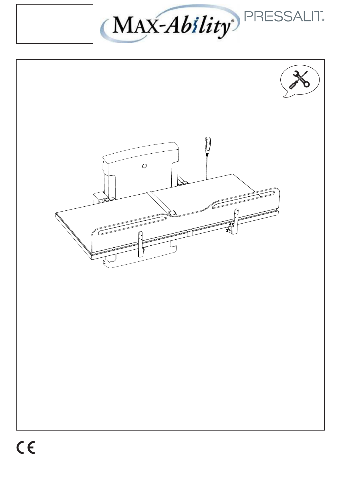
VersaMax Public Restroom
Adult Changing Table
(Electric Fold)
R8595 / R8489
Installation
Drawing
Subject to change without further notice.
1/20
Page 2
2020-02-06
Installation
Drawing
International protection rating: IPX6
Water projected in powerful jets -- from a nozzle up to 12.5 mm in size -- against the product from any direction shall have
no harmful effects.
Please note: components are included for various installation scenarios.
Please disregard any unnecessary parts.
2/20
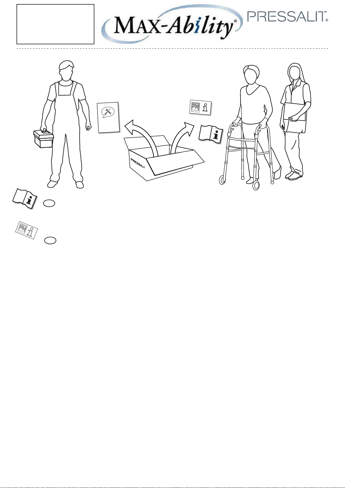
Operation and maintenance manual (OMM) for this product is enclosed in the box. Please hand over to the
EN
user. It can also be downloaded at www.pressalit.com.
An operation signage (quick guide) for use by people with reading or cognitive disabilities, is enclosed in
EN
the box. It can also be downloaded at www.pressalit.com. User information is not available in braille.
Page 3
2020-02-06
Installation
Drawing
3/20
Mounting Instruction
Please read and carefully follow these instructions. Find the product number on the product label and ensure that these assembly
instructions match your product.
WARNING: Failure to comply with these instructions may result in accidents involving serious personal injury or the product being
damaged.
WARNING: If you suspect that any individual parts may be damaged, contact your Pressalit dealer or service provider. Do not
remove, attempt to repair or install parts yourself, unless directed to do so by Pressalit or its agents.
WARNING: No modification of this equipment is allowed without express authorization from Pressalit.
WARNING: These instructions must be followed, and the product must be installed professionally by a qualified person; e.g. a
licensed plumber, in order to avoid personal injury or property damage while using the product.
WARNING: Pressalit cannot be held liable for injury to persons or damage to property caused by faulty mounting.
Installation location
This product is designed for indoor use in a wet environment, such as a bathroom or washroom. It may only be used in an environment
corresponding to the system’s IP rating. Ensure that the installation location environment also complies with the following operating
parameters of the product:
Environmental factor Operating range
Temperature 5°C to 40°C
Relative humidity 20% to 90% @ 30°C (condensation free)
Atmospheric pressure 700 to 1060 hPa
WARNING: Medical electrical equipment needs special precautions regarding electromagnetic compatibility (EMC) and needs
to be installed and put into service in accordance with the EMC information (provided in your product’s operating instructions).
It is unlikely that the user will encounter problems with the product because of inadequate electromagnetic compatibility.
However, electromagnetic immunity is always relative and standards anticipate environments of usage. Portable and mobile RF
communications equipment can affect medical electrical equipment. When the product is connected to the local mains power
supply, we recommend the use of electromagnetic shielding and similar preventative measures to avoid conducted emissions.
When choosing an installation location, ensure that there will be adequate space for movement of—and access to—the product.
Assembly and installation
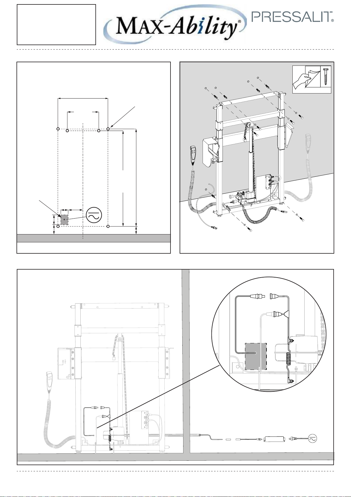
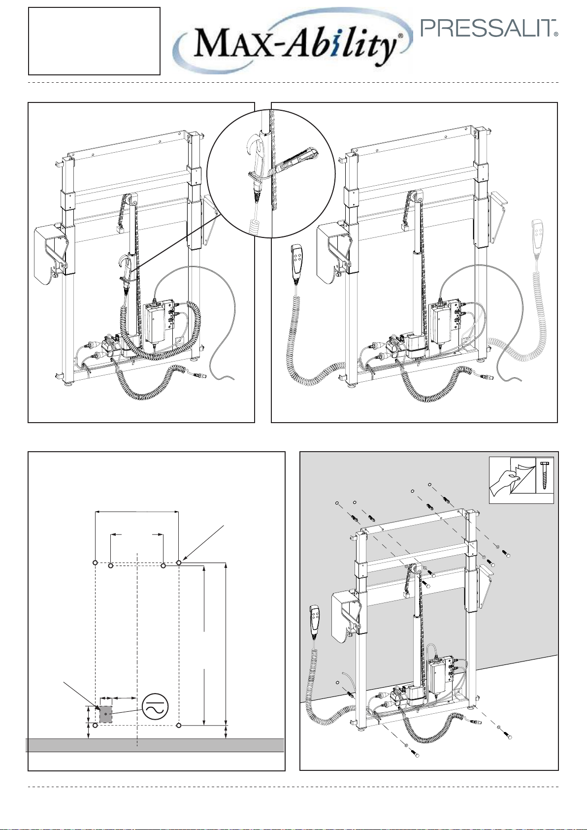
Mount the product against a wall in accordance with the illustrations in this assembly instruction. Connect the product components—hand
control unit, motor, control box and power cable—to each other as shown. Ensure that the connectors are pressed in as far as possible into
their corresponding sockets.
Connection to the mains supply
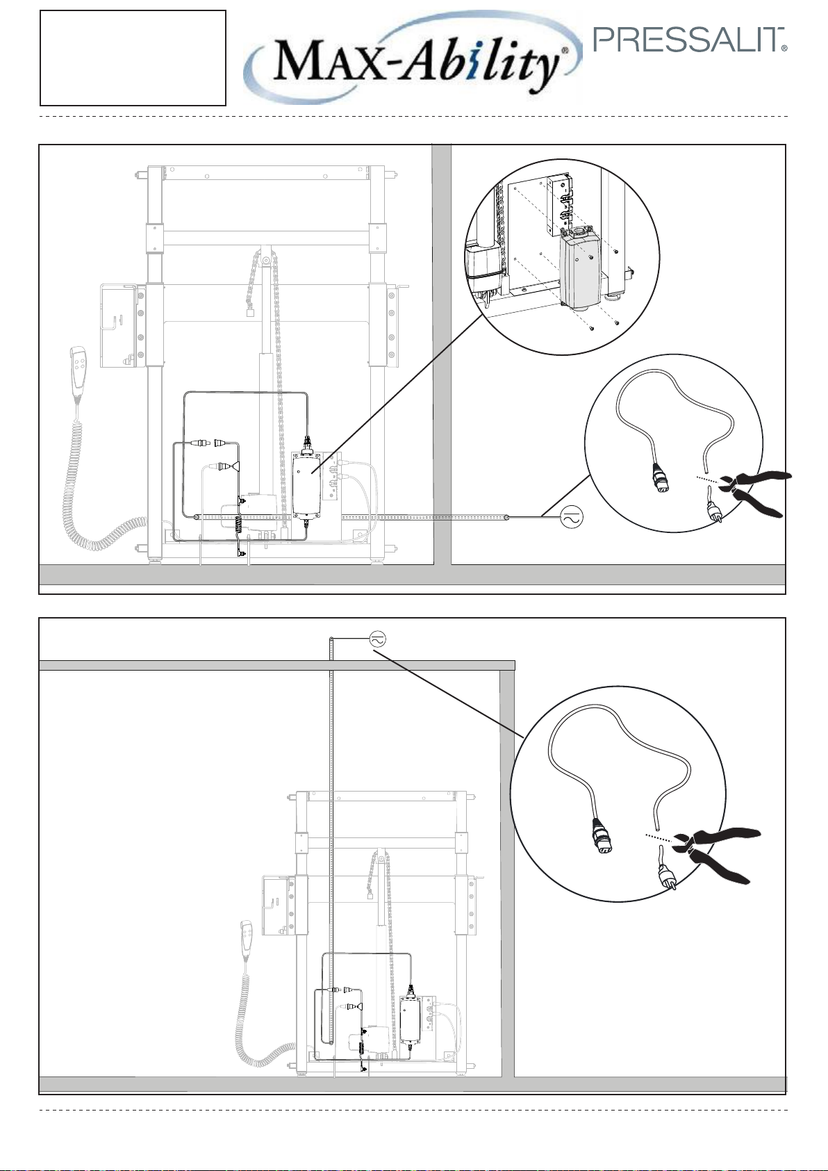
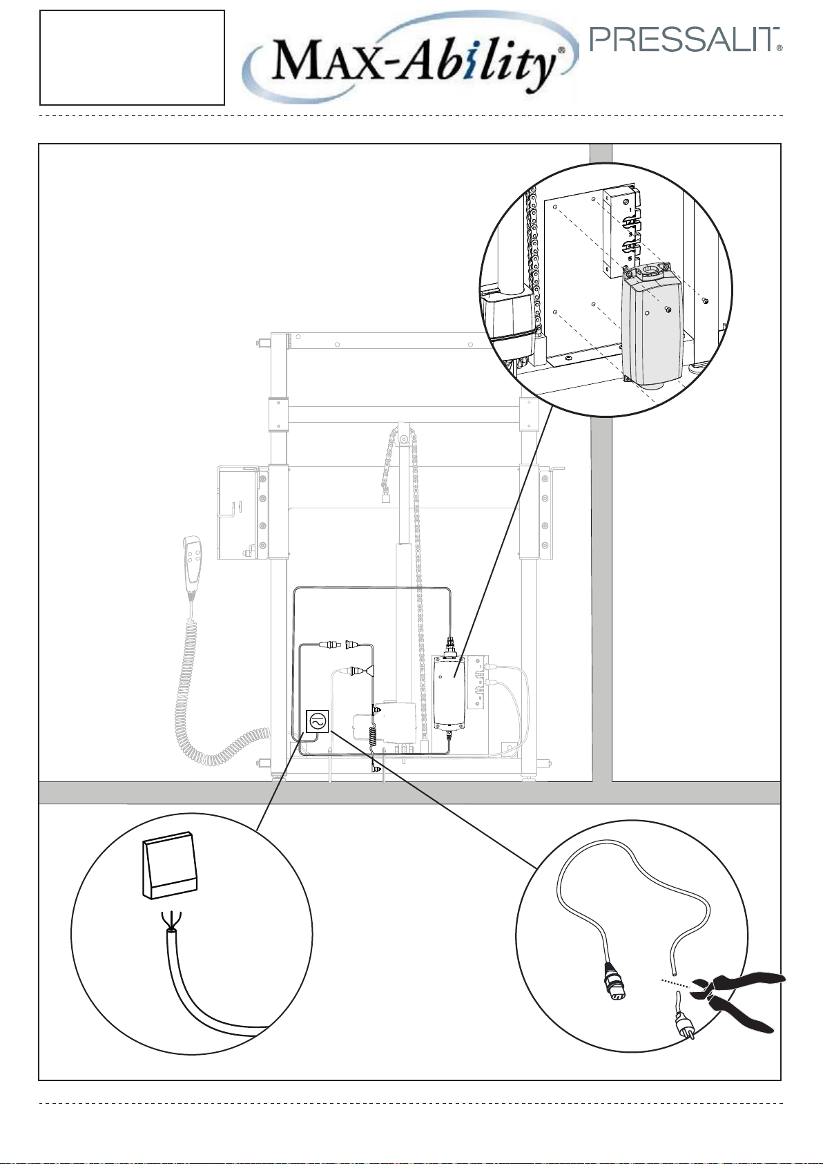
There is a range of potential configurations to connect the product to the mains power supply. See pages with . The product is supplied
with a plug attached, but this may need to be replaced with an IP-rated plug and socket combination appropriate to the location of the
socket relative to moisture, or alternatively the product may be hardwired to a mains supply.
WARNING: Ensure that the circuit on the mains supply side is isolated from power while connecting the product to the mains
supply.
WARNING: The product must be connected to the mains supply and a protective earth connection by a qualified electrician in
accordance with IEC 60601-1 and IEC 60364-7, as well as any locally applicable standards.
WARNING: Ensure that the voltage of the local mains supply to be connected is compliant with that stated on the label on the
product.
WARNING: To ensure protection by electrical separation, the product must be supplied by a mains supply circuit that does not
supply power to any other equipment, unless it incorporates a residual current protective device (RCD) with a rated residual
operating current not exceeding 30 mA. The circuit must be grounded using a protective earth connection and able to be isolated
from mains supply by means of a switch installed in a wall or cabinet.
WARNING: The integrity of the external protective earthing system must be verified.
WARNING: The installer must verify that the protective earth terminal of the control box is connected to the external protective
earthing system.
WARNING: Ensure that location of the mains isolation switch or coupling is easy to access and use.
WARNING: External cables need to be fixed in such a way that users cannot stumble and injure themselves.
Troubleshooting
If the product does not function, check that that all cables are securely connected, and that the electrical circuit is powered. A more detailed
troubleshooting guide can be found in the product’s operation and maintenance manual. Contact your Pressalit agent, if assistance is
needed when installing the product.
Page 4
!
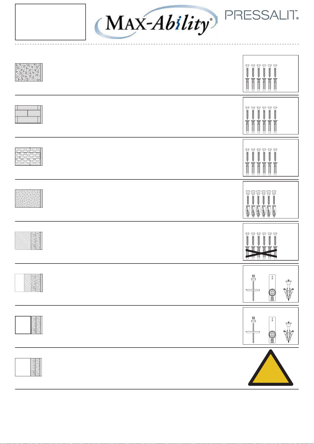
Concrete >B25
Drywall water-resistant
Solid Brick >= Mz12
Solid Sand Lime Brick >= Hlz12
Aerated Concrete P4
Drywall water-resistant, re-enforced with wood
Drywall water-resistant, re-enforced with plywood
Drywall water-resistant, re-enforced with steel plates
(2 x 12,5 mm)
22 mm
(2 x 12,5 mm)
2 mm
(2 x 12,5 mm)
Installation
Drawing
Concrete anchors included at no additional charge.
4/20
V8608
Ø10 x 70
fischer SX 12
V8608
Ø10 x 70
fischer SX 12
V8608
Ø10 x 70
fischer SX 12
V8658
Ø10 x 70
fischer GB 14
V8608
Ø10 x 70
fischer SX 12
(2 x 12,5 mm)
fischer KD 8 snaptight wingit
fischer KD 8 snaptight wingit
Page 5
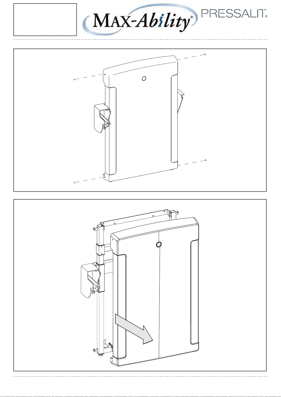
2020-02-06
Installation
Drawing
5/20
Page 6
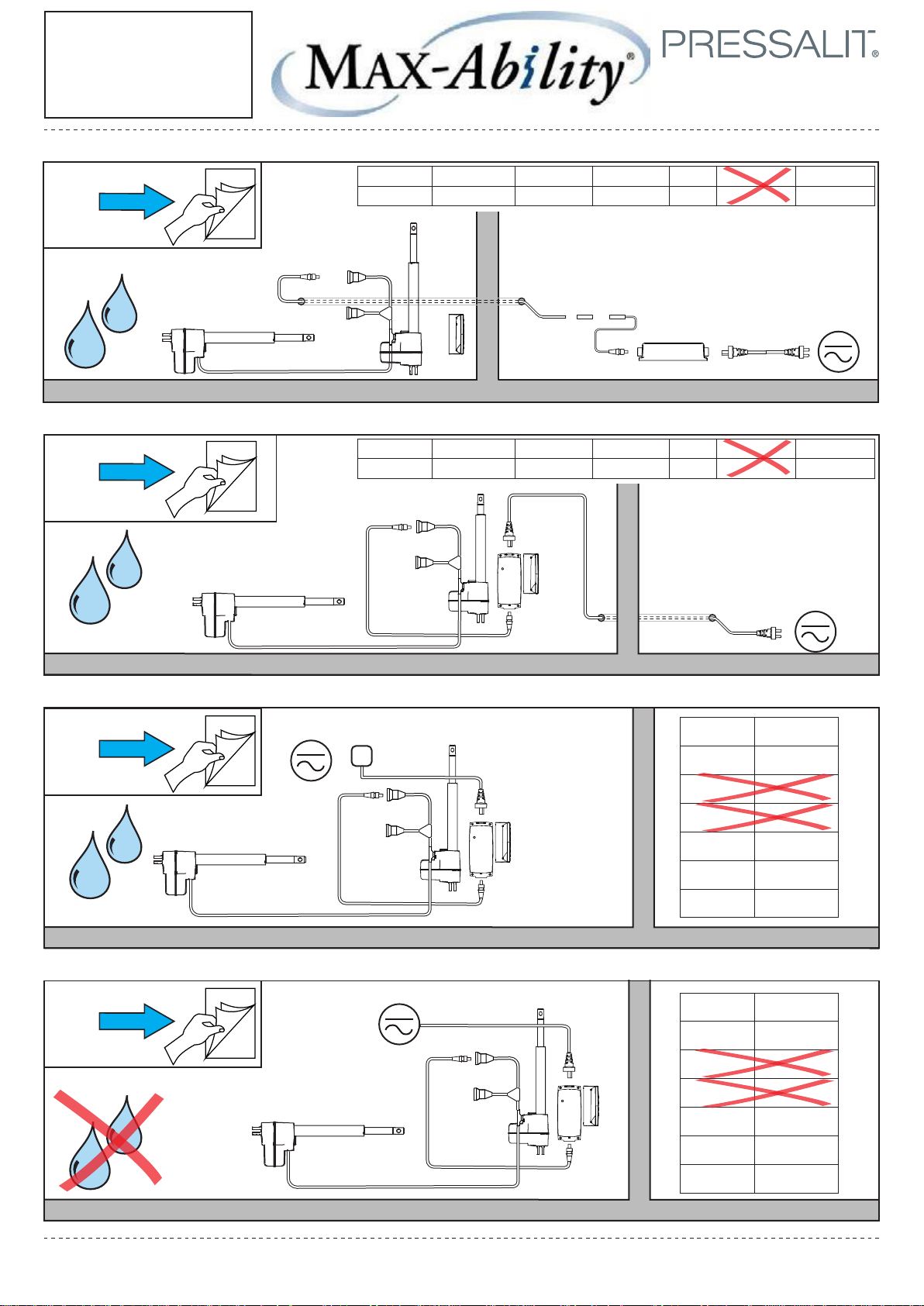
A
Installation
Options
Choose your installation method according to room environment and wiring needs:
6/20
Wet room/8000mm cable
to adjacent room
Wet room/<8m cable
to adjacent room
Wet room/hard wire
within installation
room.
Dry room/Hard wire or
wall outlet
within
installation room
(detailed diagrams: pp 7-9)
(detailed diagrams: pp 10-11)
(detailed diagrams: pp 12-13)
(detailed diagrams: pp 14-15)
7
10
12
14
B
G
A B C D E F G
3000mm 100-240V 1500mm 8000mm 24V 1500mm 24V
E
D
A B C D E F G
3000mm 100-240V 1500mm 8000mm 24V 1500mm 24V
E
C
B
A
C
D
G
G
F
A
F
B
E
B
A
E
A
A 3000mm
B 100-240V
C 1500mm
D 8000mm
E 24V
F 1500mm
G 24V
A 3000mm
B 100-240V
C 1500mm
D 8000mm
G
F
B
E 24V
F 1500mm
G 24V
Page 7
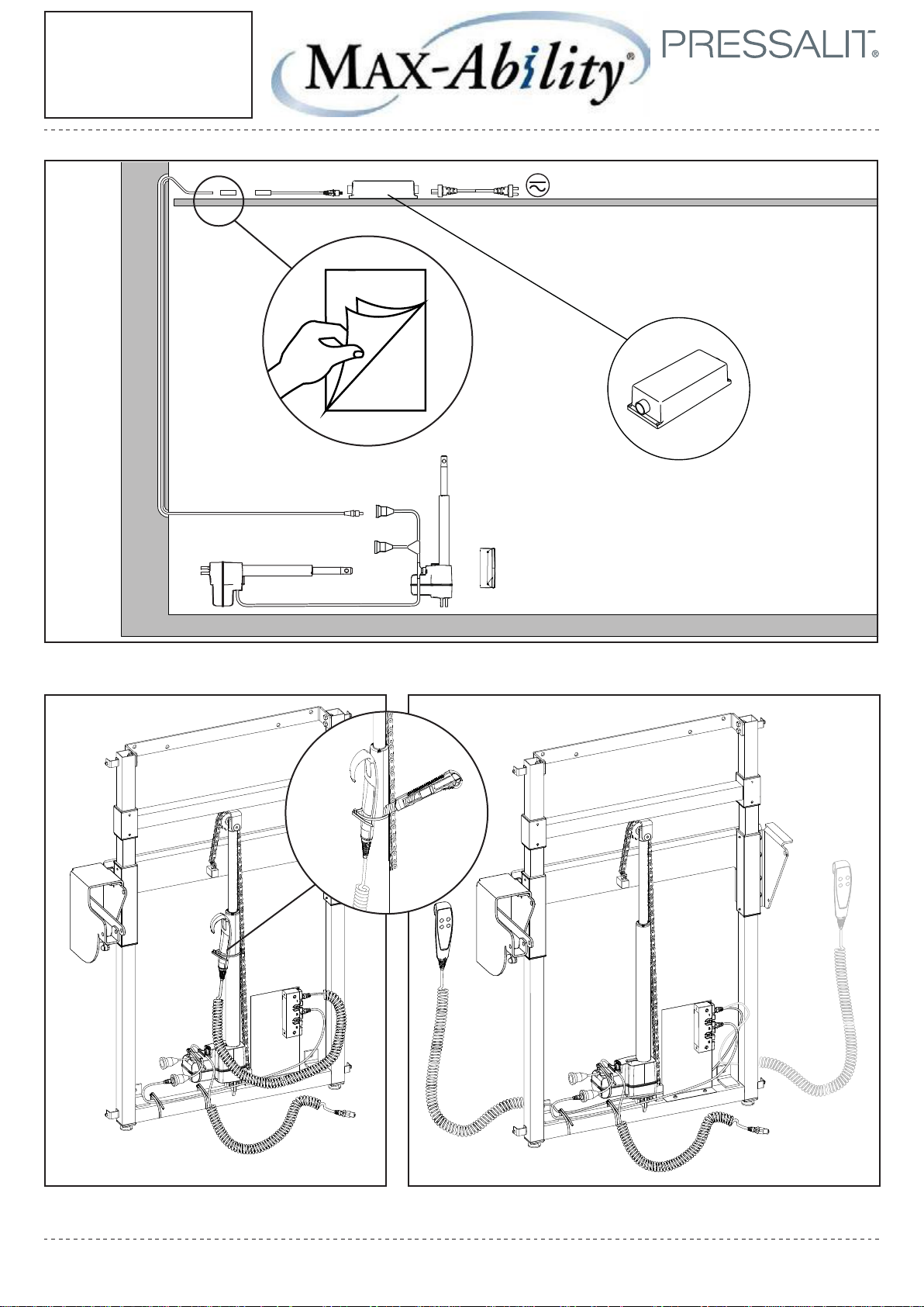
A
7/20
Detailed Diagram
Option A (from p. 6)
Wet room environment/wired to adjacent room with 8m cable
8
2020-02-06
Page 8
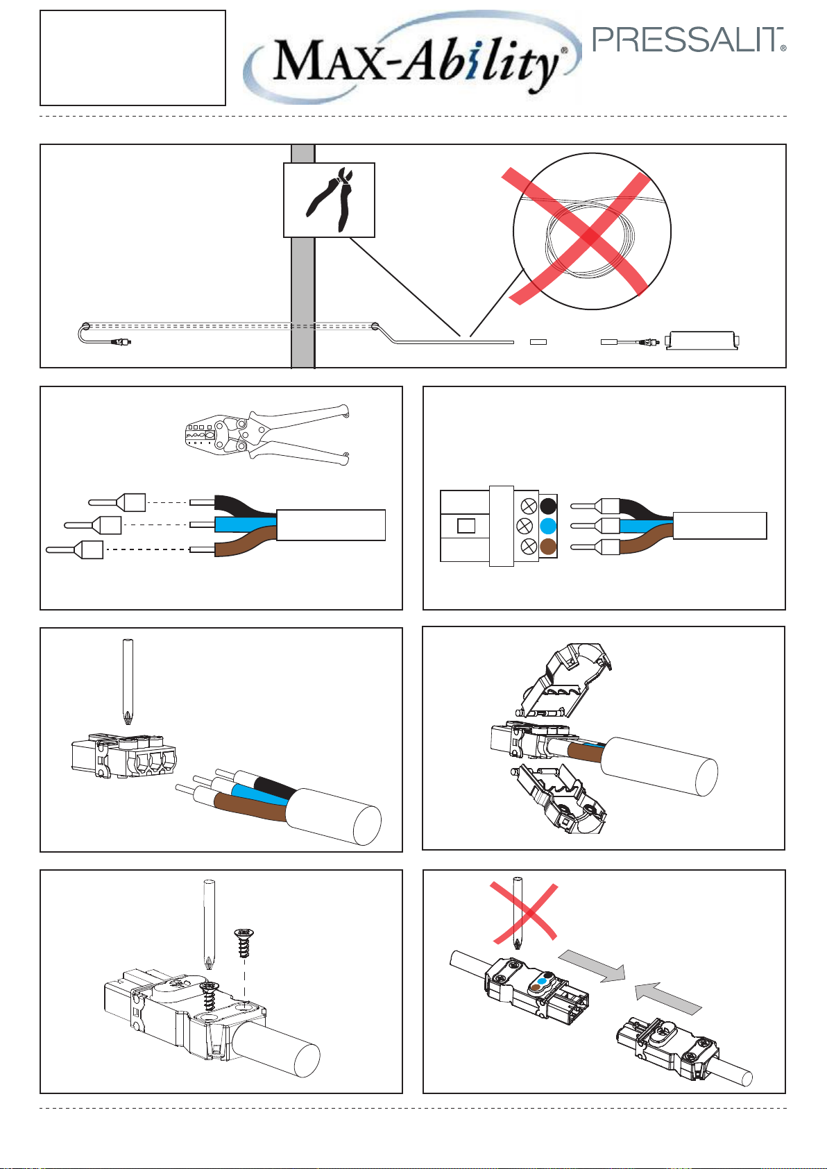
①
8/20
Detail: Block Assembly
connecting Cable D to C
(Option A only)
A
D
② ③
D
④ ⑤
C
1
2
3
B
D
⑥ ⑦
D
D
C
D
1
2
3
D
Page 9
AB
D
C
E
540
D
E
9/20
Detailed Diagram:
Option A (cont.)
4
(21⁄)
340
(13³⁄8)
2020-02-06
Ø12 (4/8)
Ø6 (2/8)
130 (5¹⁄8)
90 (3⁹⁄16)
100
(4)
100
(4)
1030
(40⁴⁄8)
1050
(41³⁄8)
86
(3³⁄8)
D
Page 10
B
10/20
Detailed Diagram:
Option B (from p. 6)
Wet room environment/wired to adjacent room with >8m cable
A
E
B
F
A
A
A
E
B
F
Page 11
2020-02-06
11/20
Detailed Diagram:
Option B (cont.)
4
Ø6 (2/8)
130 (5¹⁄8)
90 (3⁹⁄16)
100
(4)
540
(21⁄)
340
(13³⁄8)
100
(4)
1030
(40⁴⁄8)
Ø12 (4/8)
1050
(41³⁄8)
86
(3³⁄8)
Page 12
C
12/20
Detailed Diagram:
Option C (from p. 6)
Wet room environment/Hard wire within installation room
A
E
F
B
A
Page 13
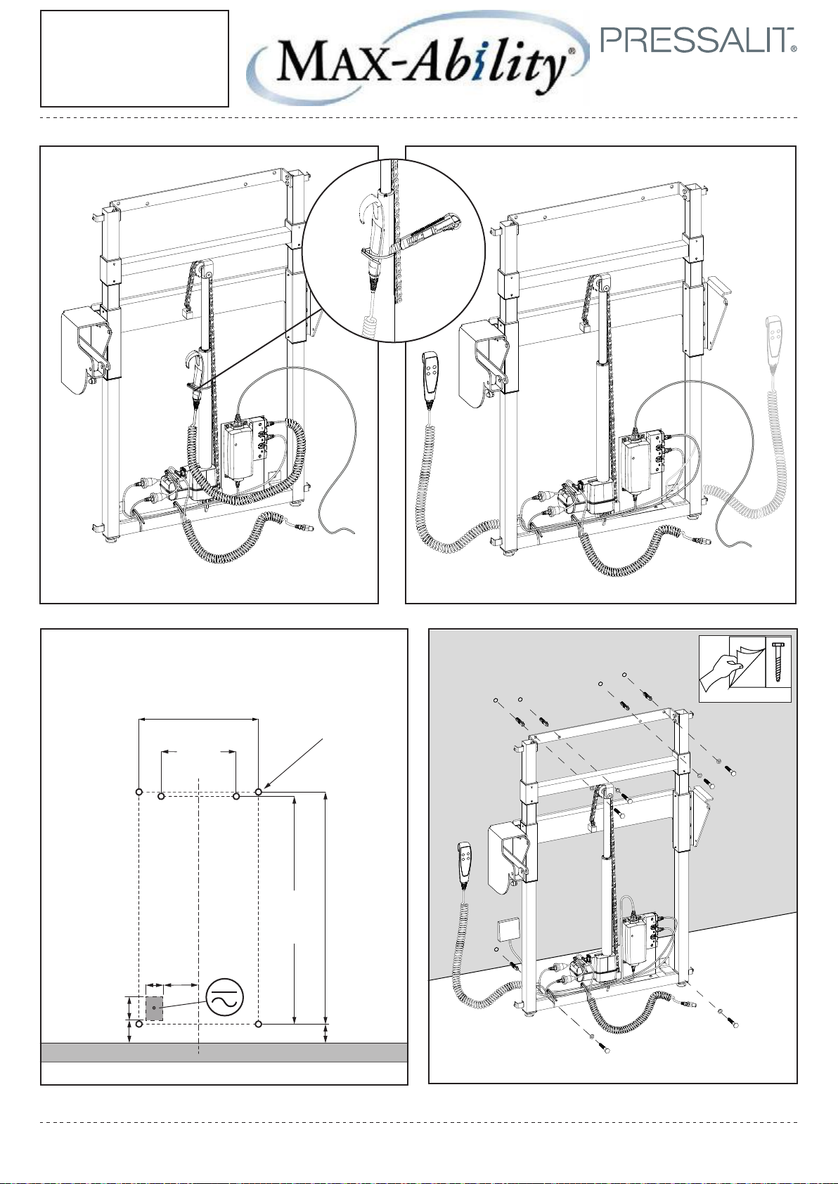
2020-02-06
13/20
4
Detailed Diagram:
Option C (cont.)
130 (5¹⁄8)
90 (3⁹⁄16)
100
(4)
540
(21⁄)
340
(13³⁄8)
100
(4)
1030
(40⁴⁄8)
Ø12 (4/8)
1050
(41³⁄8)
86
(3³⁄8)
Page 14
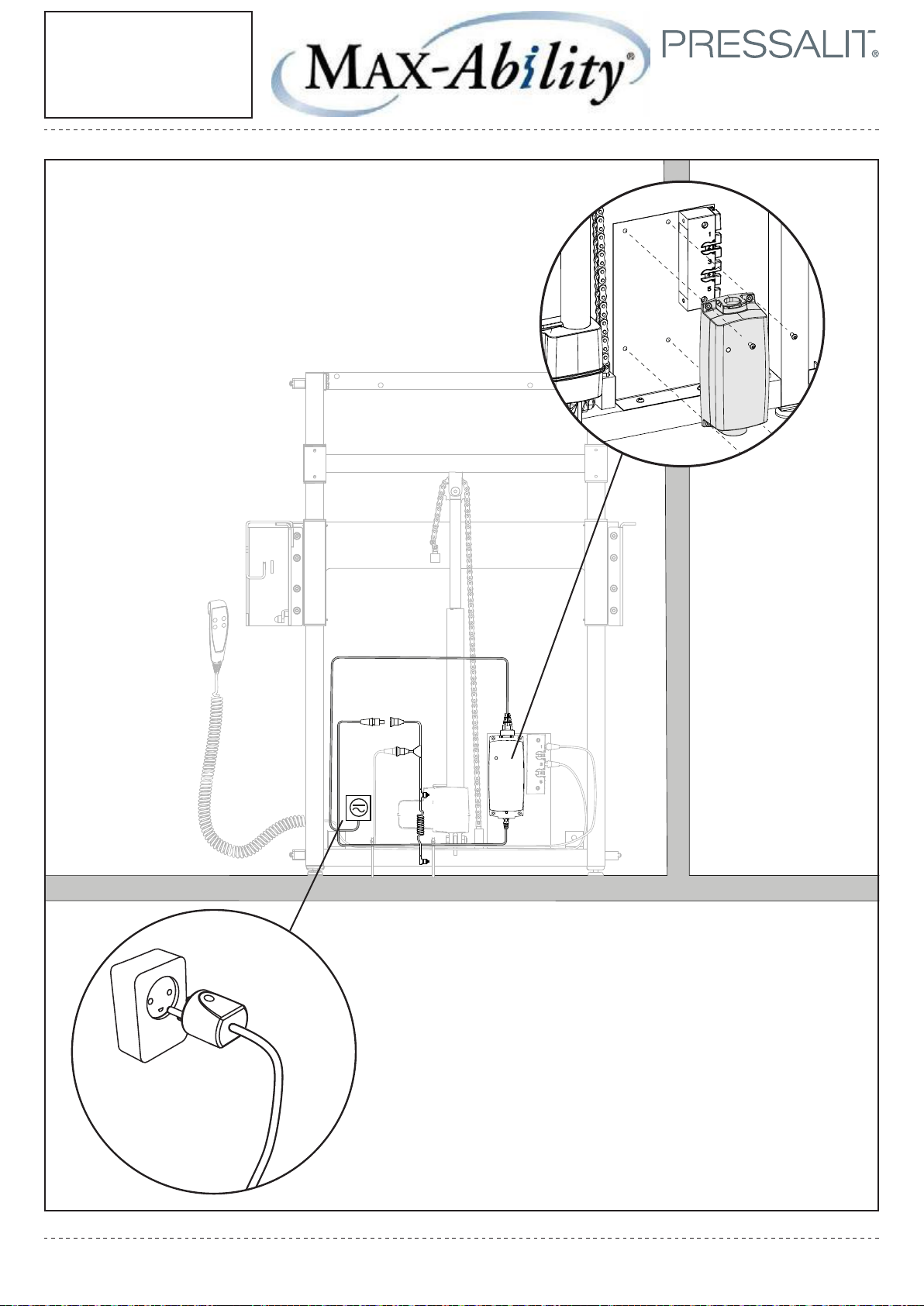
D
14/20
Detailed Diagram:
Option D (from p. 6)
Dry room environment/Wall plug or hard wire within installation room.
A
E
F
B
Page 15
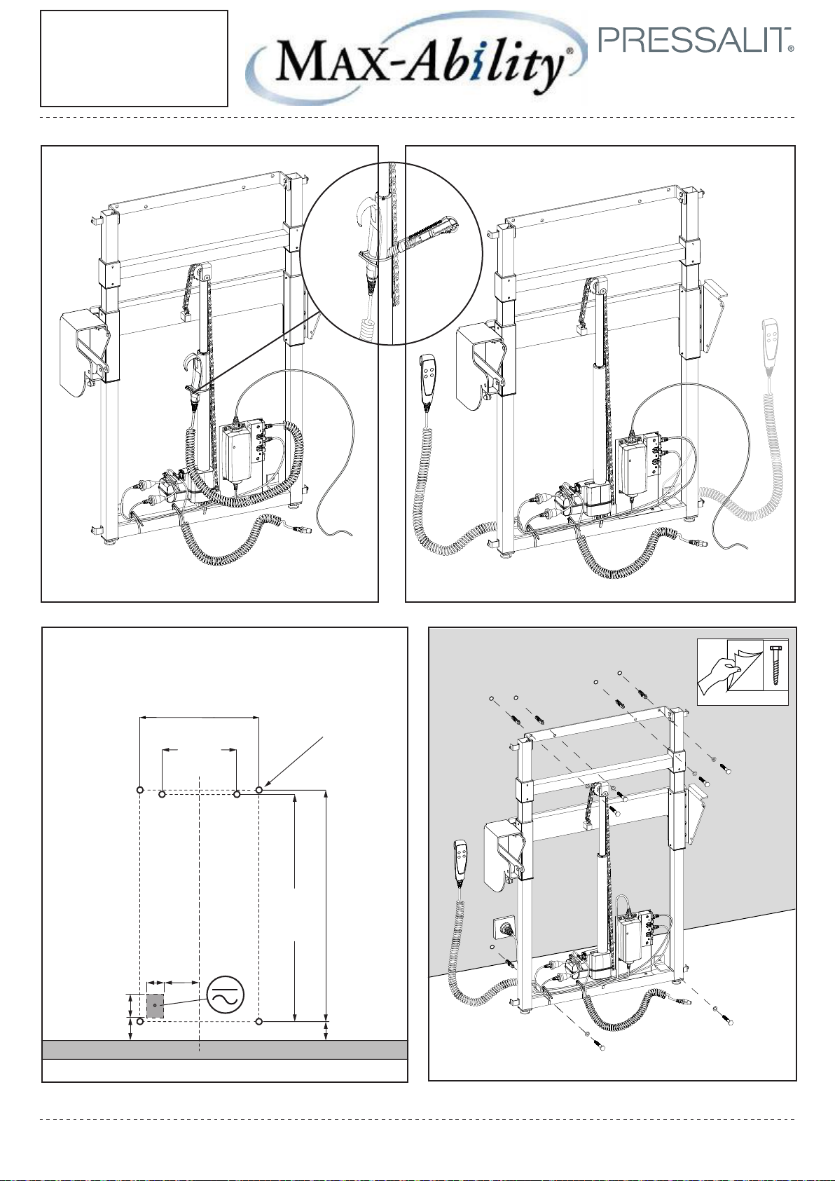
2020-02-06
15/20
Detailed Diagram:
Option D (cont.)
4
130 (5¹⁄8)
90 (3⁹⁄16)
100
(4)
540
(21⁄)
340
(13³⁄8)
100
(4)
1030
(40⁴⁄8)
Ø12 (4/8)
1050
(41³⁄8)
86
(3³⁄8)
Page 16
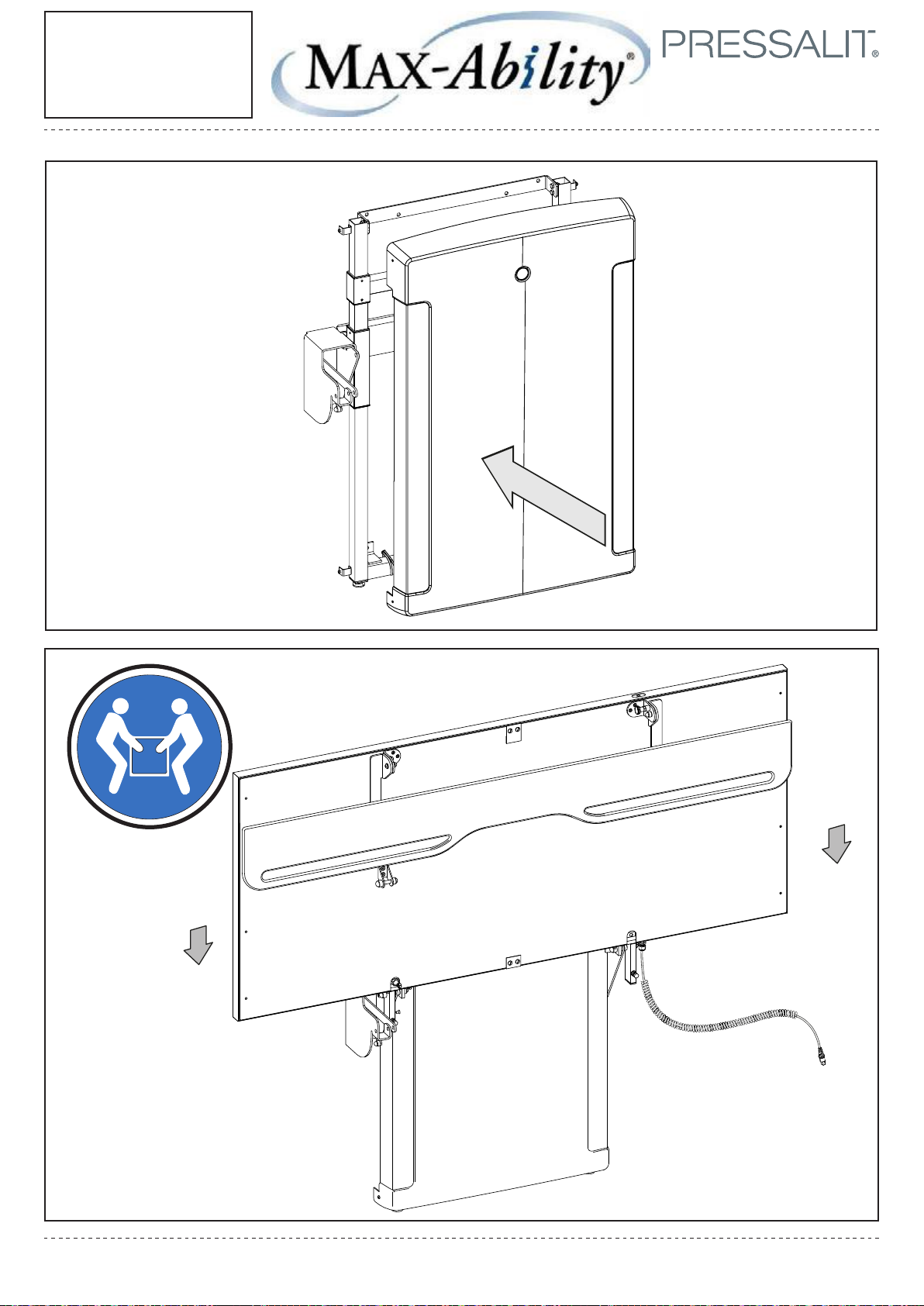
16/20
Installation
Completion
Page 17
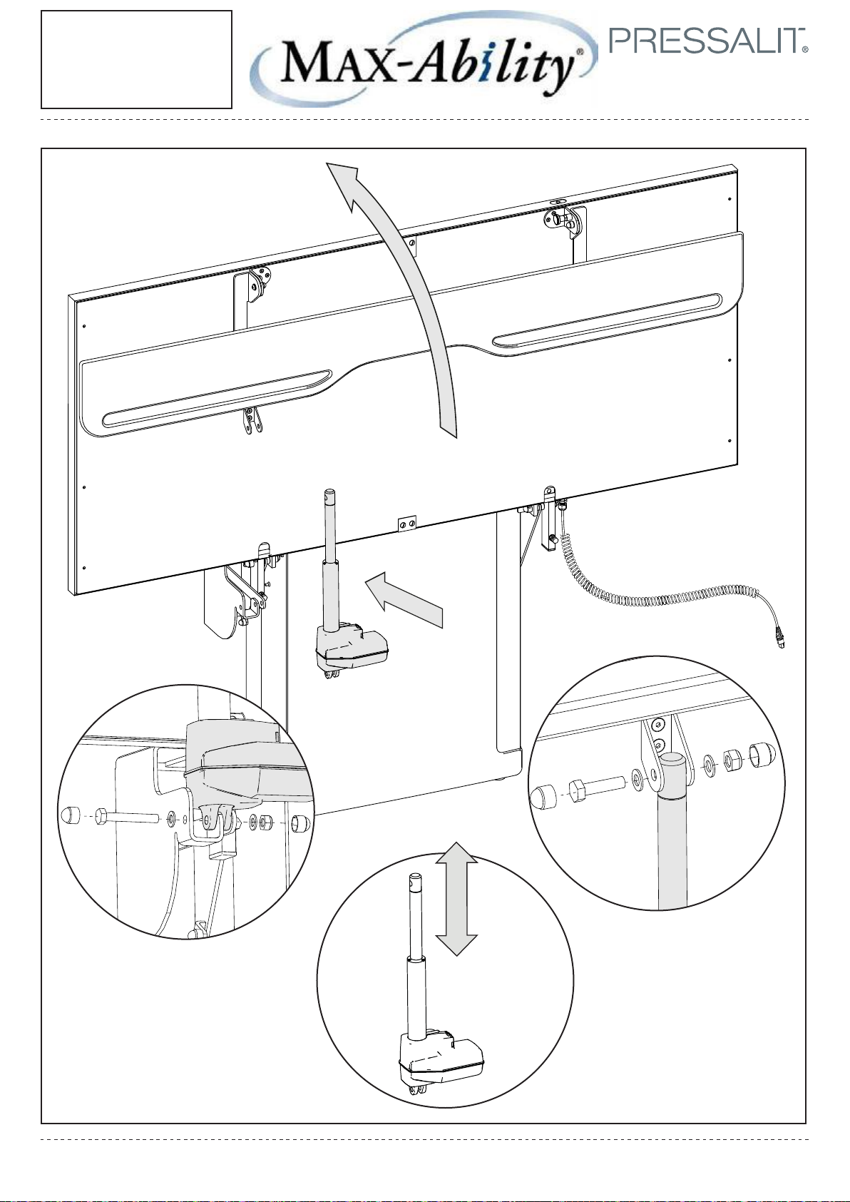
①①
17/20
Installing the
Electric Fold Motor
2020-02-06
②②
④④
③③
Page 18
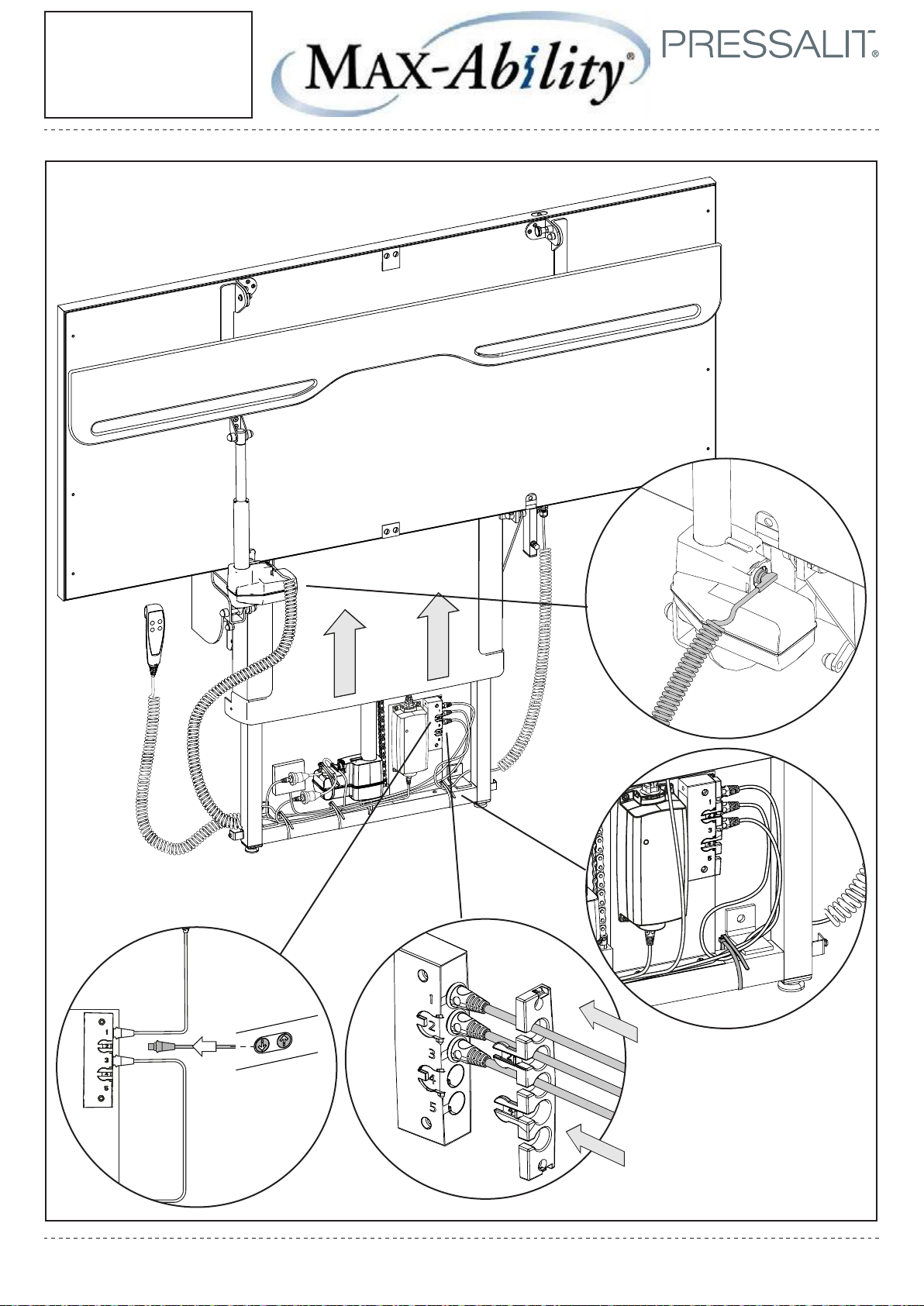
1
2
3
4
5
④④
18/20
Final Steps
③③
②②
①①
Page 19
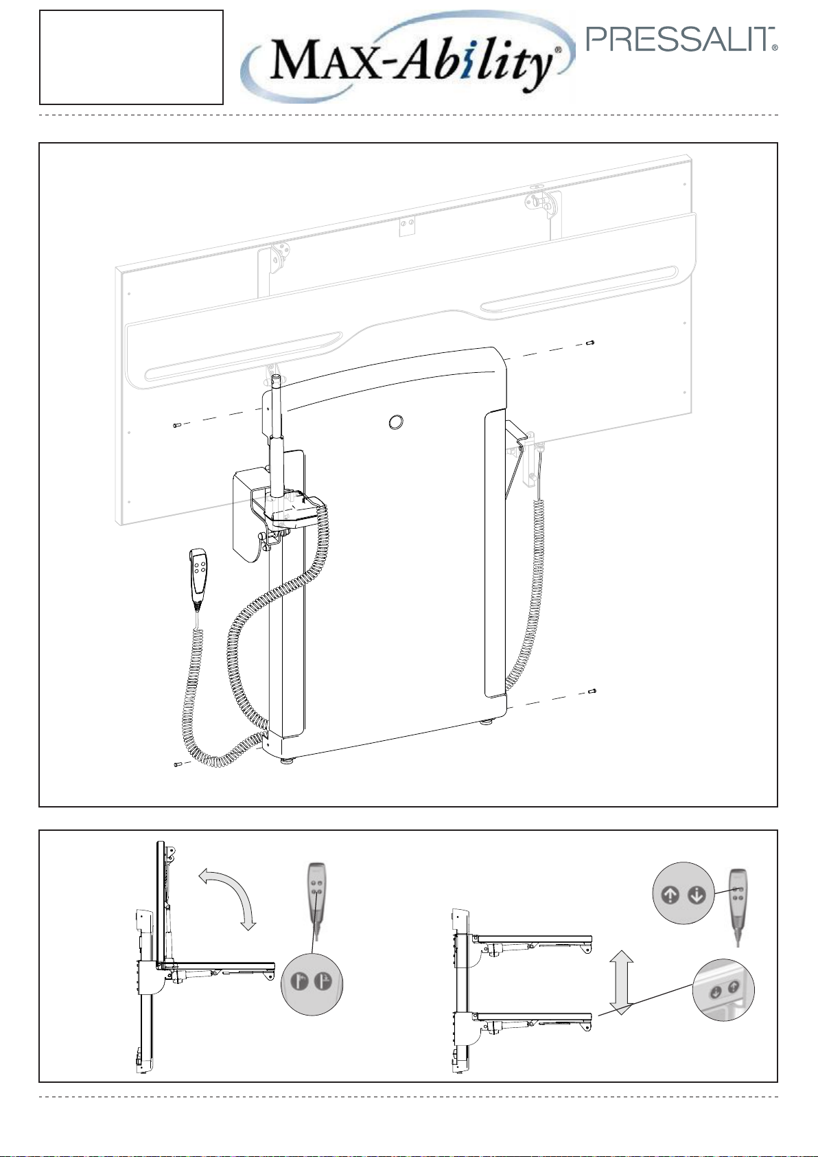
2020-02-06
19/20
Attaching
Changing Table
Cover
Page 20
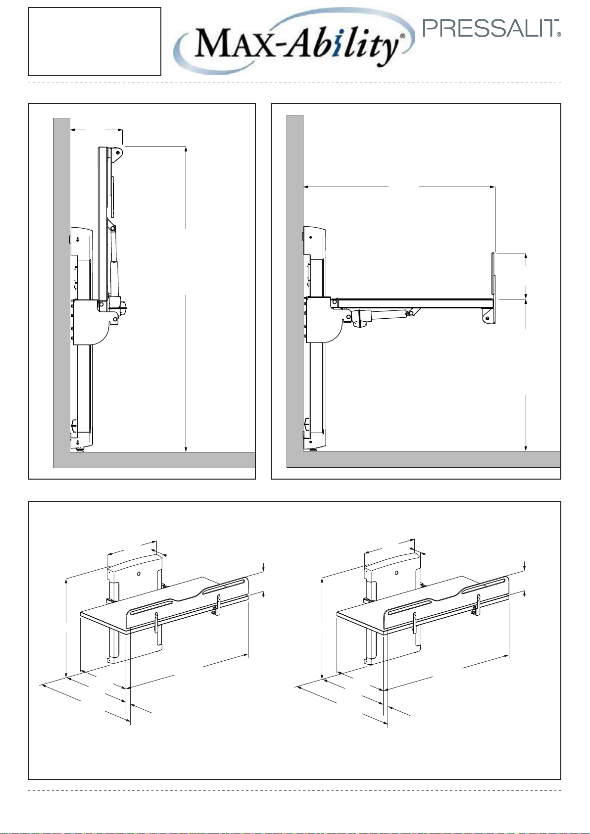
270
20/20
VersaMax
Changing Table
Dimensions
(10⁄)
Max
1830
(72)
Min
1130
(44⁄)
1020
(40⁄)
160
(6⁄)
Max
1000
(39⁄)
Min
300
(11⁄)
1180
1005
1020
813
750
10
115
1829
160
46⁄
40⁄
39⁄
32
29⁄
4⁄
6⁄
72
⁄
 Loading...