

Presence A-120 Owner's Manual
A-120
OWNER’S MANUAL
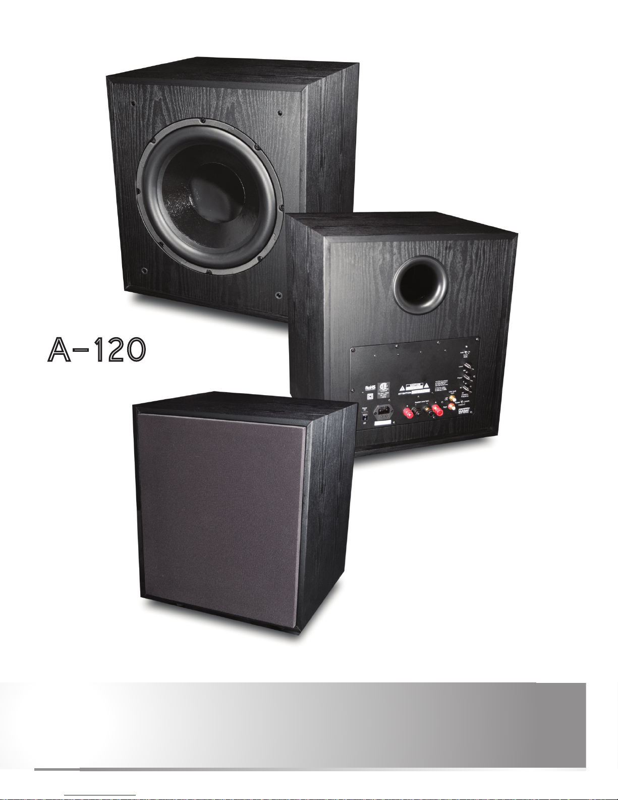
300 Watt Powered Subwoofer
12” E X T R A L O N G –T H R O W
Heavy Duty Woofer
F R E E - S T A N D I N G
P O W E R E D S U B W O O F E R
®
Presence
I M P O R T A N T S A F E T Y I N S T R U C T I O N S
Read these instructions.
Keep these instructions.
Heed all warnings.
Follow all instructions.
Do not use this apparatus near water.
Clean only with dry cloth.
Do not block any ventilation openings. Install in accordance with the manufacturer’s instructions.
Do not install near any heat sources such as radiators, heat registers, stoves, or other apparatus
(including ampliers) that produce heat.
Do not defeat the safety purpose of the polarized or grounding-type plug. A polarized plug has two blades
with one wider than the other. A grounding type plug has two blades and a third grounding prong. The
wide blade or the third prong are provided for your safety. If the provided plug does not t into your outlet,
consult an electrician for replacement of the obsolete outlet.
Protect the power cord from being walked on or pinched particularly at plugs, convenience receptacles, and
the point where they exit from the apparatus.
Only use attachments/accessories specied by the manufacturer.
Unplug this apparatus during lightning storms or when unused for long periods of time.
Refer all servicing to qualied service personnel. Servicing is required when the apparatus has been dam-
aged in any way, such as power-supply cord or plug is damaged, liquid has been spilled or objects have
fallen into the apparatus, the apparatus has been exposed to rain or moisture, does not operate normally,
or has been dropped.
WARNING: To reduce the risk of re or electric shock, this apparatus should not be exposed to rain or mois-
ture and objects lled with liquids, such as vases, should not be placed on this apparatus.
To completely disconnect this equipment from the mains, disconnect the power supply cord plug from the
receptacle.
The mains plug of the power supply cord shall remain readily operable.
W A R N I N G C A U T I O N
The lightning ash with arrowhead
symbol within an equilateral triangle, is intended
to alert the user to the presence of uninsulated
“dangerous voltage’’ within the product’s en-
closure that may be of sufcient magnitude to
constitute a risk of electric shock to persons.
The exclamation point within an equilateral triangle is intended to alert the user to the
presence of important operating and maintenance
(servicing) instructions in the literature accompanying the product.
!
A-120
O W N E R ’ S M A N U A L
2
A-120
OWNER’S MANUAL
C O N T E N T S
I M P O R T A N T S A F E T Y I N S T R U C T I O N S 2
Y O U R A - 1 2 0 P O W E R E D S U B W O O F E R 2
AT T A C H I N G T H E F E E T 4
F E AT U R E S 4 - 5
C O N N E C T I O N 5 - 7
S E T U P 8 - 10
Placement 8
A-120 Controls 9
Fine Tuning the Controls 9 - 1 0
S P E C I F I C AT I O N S 1 0
N O T E S 11
Y O U R A - 1 2 0 P O W E R E D S U B W O O F E R
Thank you for purchasing the A-120 powered subwoofer. Your subwoofer has been developed to
provide you with pleasing accurate bass in your music system or home theater sound system.
This manual covers operating procedures, general setup, and technical specications for your A-120. We
recommend that you thoroughly read through the material contained in this manual before connecting your
subwoofer. This will ensure that you have a complete understanding of how to setup and operate your
subwoofer properly for optimum performance. Thank you again for choosing the A-120, and we hope that
you enjoy the enhanced dimension that a ne subwoofer adds to the sonic experience.
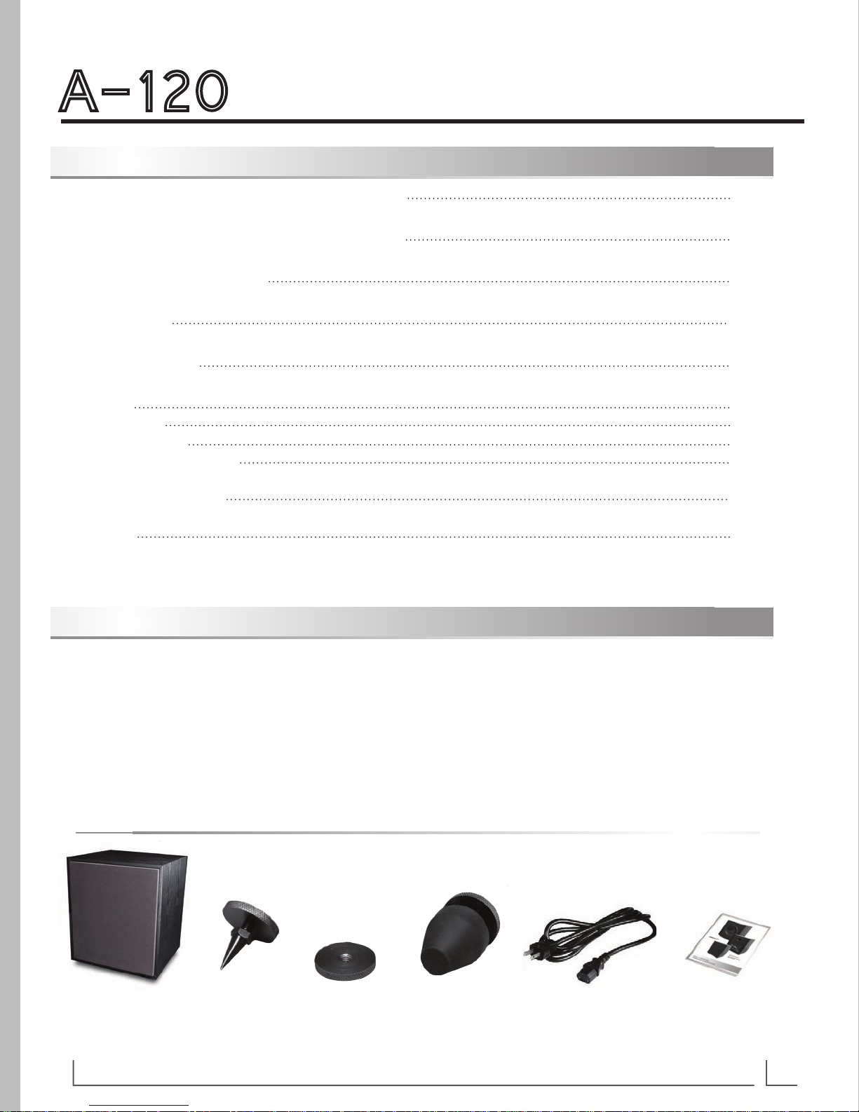
Box Contents:
Subwoofer (4) Spiked Feet (4) Knurled Lock Nuts (4) Rubber Feet Power Cord Manual &
Warranty Card
A-120
O W N E R ’ S M A N U A L
3
A T T A C H I N G T H E F E E T
After reviewing the manual and unpacking your A-120 subwoofer, we suggest that the four rubber feet be installed
on the bottom of the enclosure to protect the subwoofer and your oor or cabinetry from damage during
installation and setup. These feet can be replaced by the spikes, or removed if desired, after the nal location is
determined. Here are some guidelines for using the feet.
DO NOT try to slide your subwoofer with the feet installed. This will damage the foot supports or the feet.
If the A-120 is placed on carpet, the spikes are likely the best choice since they will penetrate the carpet
and provide a solid and stable footing for the subwoofer.
If the unit is placed on a hard surface then the rubber feet should be used.
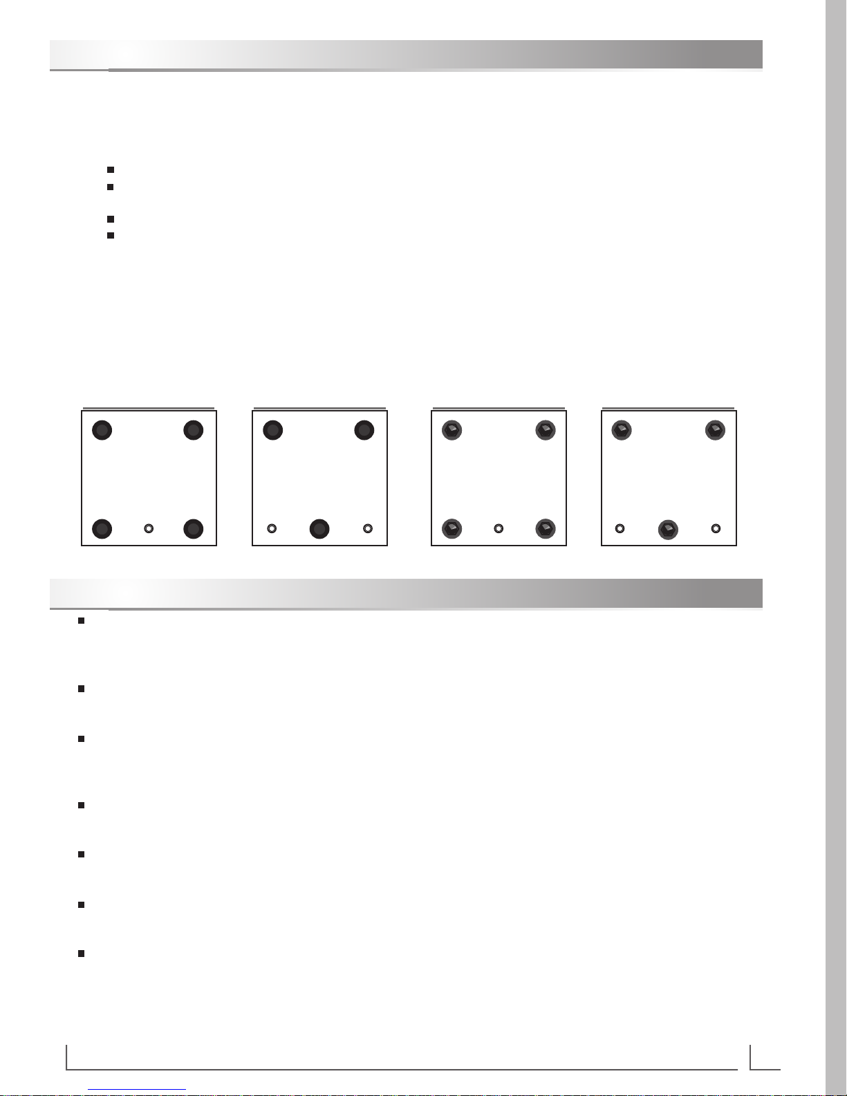
You may elect to use only three feet especially if the surface on which you are placing the subwoofer is
uneven, such as a stone or tile oor. See diagram for details.
To install the feet:
Thread the knurled jam nuts onto the desired feet and then screw the feet into the appropriate holes on the
bottom of the A-120 enclosure. Begin with the feet screwed all the way into the enclosure. Rotate the enclosure
into its upright position and lower the appropriate feet to level the subwoofer and prevent it from rocking. Finger
tighten the knurled jam nuts against the bottom of the enclosure to secure the feet and prevent them from
moving. Use care not to over-tighten the knurled jam nuts as they will be difcult to loosen.
Front of Subwoofer Front of Subwoofer
Bottom of Subwoofer
Showing (4) Rubber Feet
Front of Subwoofer Front of Subwoofer
Bottom of Subwoofer
Showing (3) Rubber Feet
Bottom of Subwoofer
Showing (4) Spiked Feet
Bottom of Subwoofer
Showing (3) Spiked Feet
F E A T U R E S
The A-120 subwoofer was designed for exceptional performance and value. It features a 12” extra-long
excursion woofer with high Bl motor. The bass reex enclosure ensures extended bass response and high
acoustic efciency.
The woofer is driven with an integral 300W class A/B amplier utilizing the patented BASH technology for high
electrical efciency.
The integral rear-mounted 300 watt amplier includes several essential controls to contour the subwoofer’s
output to blend with virtually all loudspeakers and room environments. These controls, their operation, and
their adjustment are described in a later section of this manual.
An integral low pass crossover network is continuously-variable from 40Hz to 120Hz and can be bypassed if it is
preferable to use an external crossover located in an outboard receiver or processor.
The A-120’s integral amplier incorporates a defeatable signal-sensing circuit that automatically powers up the
amplier when a signal is detected.
A double-insulated isolated-ground electrical supply prevents electrical ground loops and reduces the noise oor
of the entire audio system.
The A-120 is shipped with 8 adjustable feet, (4 spiked and 4 rubber) with tool-less knurled jam nuts. These
feet can be installed in the bottom of the enclosure in either a three-point triangular pattern or more traditional
4 point square pattern. The bottom of the enclosure has 5 threaded inserts arranged to accept either pattern.
A-120
O W N E R ’ S M A N U A L
4
 Loading...