

Page 1
Instruction
y
r
IMPORTANT SAFETY INFORMATION. READ AND FOLLOW ALL SAFETY INSTRUCTIONS. Follow label information
and instructions concerning Wet or Damp Locations, installation near combustible materials, insulation, building materials,
and proper lamping. Do not install in areas subject to combustible vapors or gases. Before wiring to power supply and
during servicing or relamping, turn off power at fuse or circuit breaker. All servicing or relamping must be performed by
qualified service personnel. Product must be grounded to avoid potential electric shock or other potential hazard.
Product must be mounted in locations and at heights and in a manner consistent with its intended use, and in
compliance with the National Electrical Code and local codes. The use of accessory equipment not recommended b
the manufacturer or installed contrary to instructions may cause an unsafe condition. Do not block light emanating from
product in whole or part, as this may cause an unsafe condition. Do not allow items such as drapes, curtains, screens or
the like to come into contact with the product or to block light from the product, as this may cause an unsafe condition.
WARNING – This product contains chemicals known to the State of California to cause cancer, birth defects and/or othe
reproductive harm. Thoroughly wash your hands after installing, handling, cleaning, or otherwise touching this product.
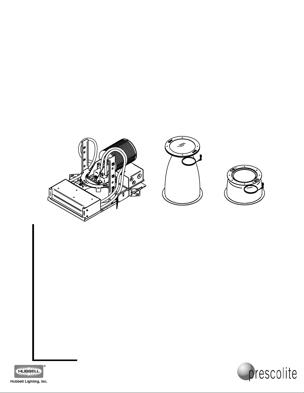
MD8LED FIXTURE AND 8MD REFLECTOR
Sheet
CAUTION: To reduce the risk of electrical shock, make certain that the power supply is
turned off before installing or servicing this product!
1. As shipped from the factory, the fixture light engine is mounted in the lowest position on the
plaster frame yoke risers. This is the correct mounting point for the 8MD 55 degree reflectors.
The only adjustment that may be necessary is the lens position adjustment. See Step 7 below
for the light engine mounting points for each reflector (25, 35, 45, 55 degree). See Step 8 for
the adjustment for lensed or open (no lens) reflectors. This can be pre-adjusted before fixture
installation, or adjusted later during the reflector installation, after the ceiling is finished.
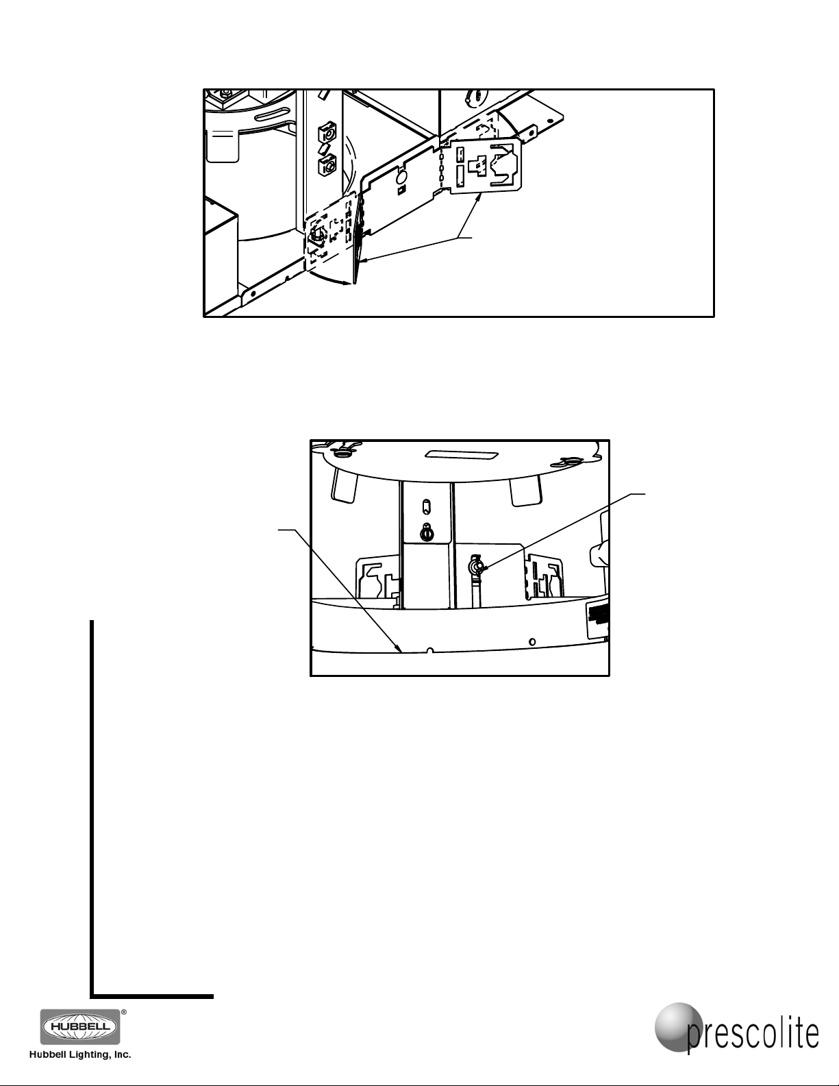
2. Bend the adjustable mounting brackets as shown in FIG. 1. Install the fixture in the ceiling using
B24 or B6 bar hangers, or using mounting channel or bar (by others) placed in the adjustable
mounting brackets. Mount the fixture so that the weight of the fixture is safely and securely
attached and supported by the building structure using the b a r hangers, mounting channel,
and/or hanger wires, or as required by local code. Do not support the fixture by attaching it to
the ceiling alone.
Part No...........................................
INSTALLATION INSTRUCTIONS
MD8LED FIXTURE
8MD 25 DEGREE
REFLECTOR
WITH LENS
8MD 55 DEGREE
OPEN REFLECTOR
(WITHOUT LENS)
93047835
PAGE 1 OF 7
www.prescolite.com y Prescolite Toll Free Technical Support 1.888.PRS.4TEC y Hours: 8am - 5pm ET
701 Mille nnium Blvd• Greenville, SC 29607
With representatives offices in principal cities throughout North America.
Copyright , revision, All Rights Reserved - Printed in U.S.A.
2013 04/12/13
Page 2
Instruction
3. Adjust the fixture vertically by loosening the wing nuts on the adjustable mounting brackets on either
side of the fixture. Important - adjust the fixture height so the bottom of the plaster flange is
Sheet
flush with the finished ceiling line and in alignment with adjacent fixtures. (See FIG. 2) Once
adjusted correctly, lock the adjustable mounting brackets by securely retightening both wing nuts.
Part No...........................................
THE ADJUSTABLE MOUNTING
BRACKETS ARE SUPPLIED FLAT.
BEND AS SHOWN TO ACCEPT THE
OPTIONAL B6 OR B24 BAR HANGERS,
OR MOUNTING CHANNEL OR BAR
(BY OTHERS).
FIG. 1
93047835
PAGE 2 OF 7
www.prescolite.com y Prescolite Toll Free Technical Support 1.888.PRS.4TEC y Hours: 8am - 5pm ET
MAKE SURE EDGE
OF PLASTER
FLANGE IS FLUSH
WITH THE FINISHED
CEILING LINE.
ADJUSTABLE
MOUNTING
BRACKET WING
NUT (ONE ON
EITHER SIDE OF
THE PLASTER FRAME)
FIG. 2
4. Determine where the supply wiring conduit will enter the J-Box, remove the appropriate J-Box
knockout, and attach the conduit.
NOTE: Make all conduit and wiring connections to the fixture in conformance with the National
Electrical Code.
5. Remove the J-Box cover plate and connect the fixture wiring using the appropriate connectors for the
supply wires used. Connect the supply ground wire to the green (ground) fixture lead. Connect the
white (common) supply wire to white fixture lead. Connect the power supply (line) to black fixture lead.
Make any control wiring connections to the control input leads (violet and gray leads for 0-10V
dimming on the standard fixture). IMPORTANT: If the control leads are not used, individually cap
off the unused leads.
Reinstall J-Box cover.
WARNING: DO NOT pinch wires between J-Box cover and J-Box. Consult a Qualified
Electrician for all other options that require other wiring configurations.
701 Mille nnium Blvd• Greenville, SC 29607
With representatives offices in principal cities throughout North America.
Copyright , revision, All Rights Reserved - Printed in U.S.A.
2013 04/12/13
Page 3
Instruction
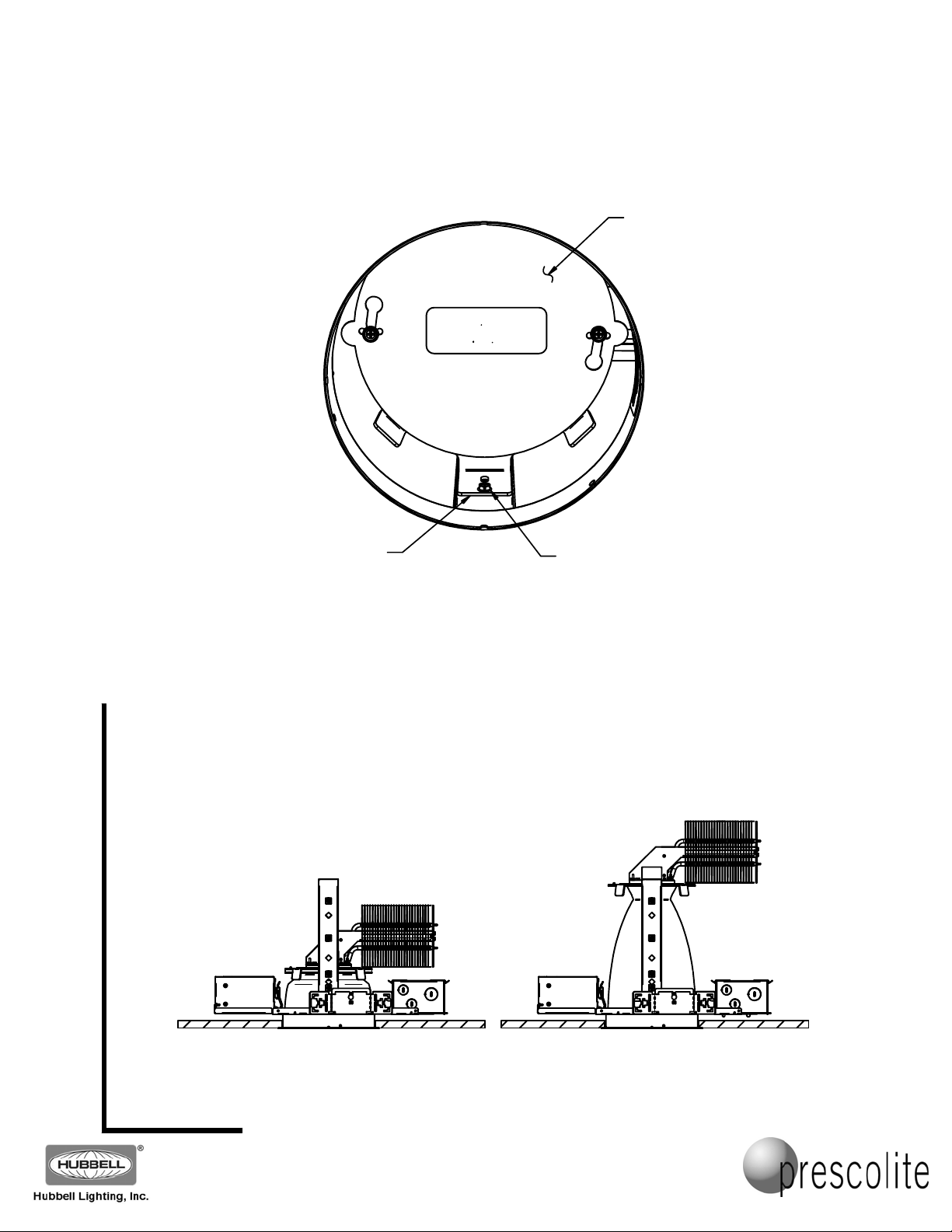
6. There is a clear protective cover installed on the light engine from the factory (See FIG. 3). This
cover is used to protect the LEDs during installation, and allows the fixture to be used for
lighting (without the reflector) during the construction phase at the worksite. Keep this cover in
place to protect the LEDs and only remove it (Step 9) after all ceiling installation and finishing
work is complete, and before installing the reflector (Step 10). Note: The reflector CANNOT be
installed with this clear cover in place.
Sheet
7. Adjust the light engine yoke to the correct height for the intended reflector (based on the light
engine output and beam angle of the reflector) by removing the two light engine yoke
adjustment screws on either side of the fixture (See FIG. 3) and moving the light engine to the
proper height for the reflector. These reflector mounting positions can be very different due to
the difference in reflector heights, as shown in the example below. (This adjustment can be
done before mounting the fixture in the ceiling as mentioned in Step 1, above).
LIGHT
ENGINE
YOKE
REMOVE AND DISCARD THIS
CLEAR PROTECTIVE COVER
AFTER THE CEILING IS FINISHED
AND BEFORE MOUNTING THE
REFLECTOR!
FIG. 3
93045753
Part No...........................................
CLEAR PROTECTIVE
COVER ON LIGHT ENGINE
(SHOWN THROUGH
CEILING CUTOUT)
LIGHT ENGINE YOKE
ADJUSTMENT SCREW
(ONE OF TWO)
93047835
PAGE 3 OF 7
www.prescolite.com y Prescolite Toll Free Technical Support 1.888.PRS.4TEC y Hours: 8am - 5pm ET
8MD 55 DEGREE REFLECTOR
WITH LENS MOUNTED
IN MD8LED FIXTURE
701 Mille nnium Blvd• Greenville, SC 29607
With representatives offices in principal cities throughout North America.
Copyright , revision, All Rights Reserved - Printed in U.S.A.
2013 04/12/13
8MD 25 DEGREE REFLECTOR
WITHOUT LENS MOUNTED
IN MD8LED FIXTURE
Page 4
Instruction
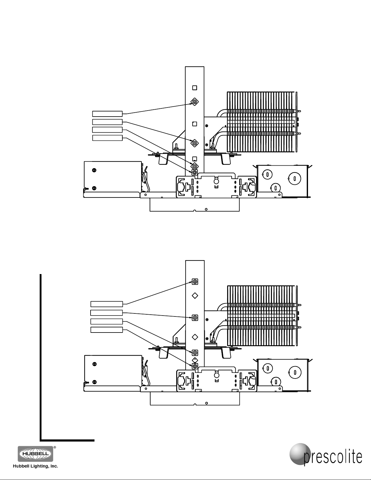
The MD8LED3L (3000 Lumen) and MD8LED6L (6000 Lumen) housings have light engine/reflector
mounting locations as detailed in FIG. 4.
Sheet
& MD8LED6L (6000 LUMEN)
LIGHT ENGINE / REFLECTOR
MD8LED3L (3000 LUMEN)
MOUNTING POSITIONS
3L & 6L 25 DEG
3L & 6L 35 DEG
3L & 6L 45 DEG
3L & 6L 55 DEG
FIG. 4
Part No...........................................
93047835
PAGE 4 OF 7
www.prescolite.com y Prescolite Toll Free Technical Support 1.888.PRS.4TEC y Hours: 8am - 5pm ET
The MD8LED9L (9000 Lumen) and MD8LED12L (12000 Lumen) housings have light engine/reflector
mounting locations as detailed in FIG 5.
MD8LED9L (9000 LUMEN)
MD8LED12L (12000 LUMEN)
LIGHT ENGINE / REFLECTOR
MOUNTING POSITIONS
9L & 12L 25 DEG
9L & 12L 35 DEG
9L & 12L 45 DEG
9L & 12L 55 DEG
FIG.5
701 Mille nnium Blvd• Greenville, SC 29607
With representatives offices in principal cities throughout North America.
Copyright , revision, All Rights Reserved - Printed in U.S.A.
2013 04/12/13
Page 5
Instruction
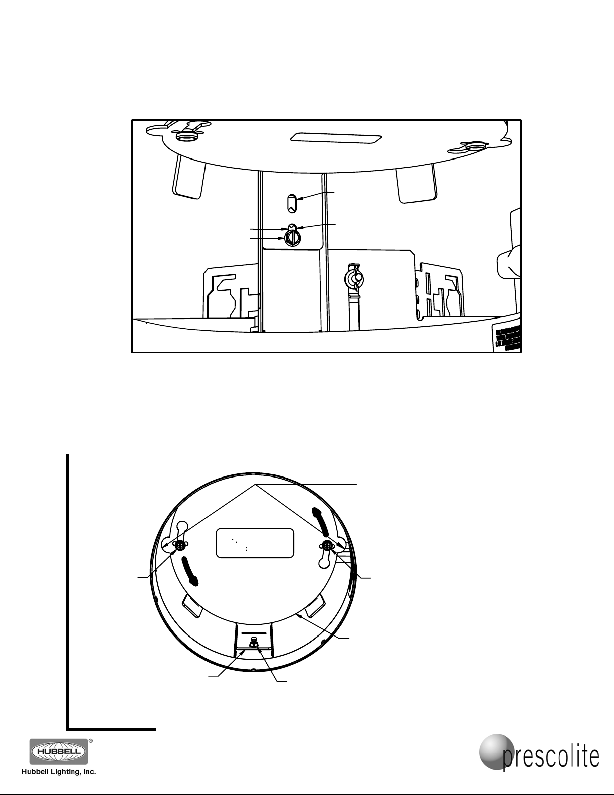
8. After positioning the light engine at the proper mounting location, reinstall the mounting screws in the
lower slots on the light engine yoke bracket. Adjust the light engine as shown in FIG. 6 below to position
it for either the lensed version of the reflector, or the open (no lens) version of the reflector by using the
vertical adjustment slot in the light engine yoke mounting bracket.
Part No...........................................
93047835
PAGE 5 OF 7
www.prescolite.com y Prescolite Toll Free Technical Support 1.888.PRS.4TEC y Hours: 8am - 5pm ET
Sheet
9. After all ceiling installation and finishing work is complete, and before installing the reflector, remove the
DO NOT
USE
NO LENS POSITION
LENSED POSITION
LIGHT ENGINE YOKE
MOUNTING SLOT
FIG. 6
ATTACHING THE 8MD REFLECTOR
clear protective cover from the light engine by rotating it counter-clockwise to unlock it, and then remove
it from the reflector mounting buttons. (See FIG. 7) This cover can be kept to protect the LEDs if future
ceiling refinishing is ever needed, or discarded (please recycle – it is made of polycarbonate plastic).
REMOVE AND DISCARD THIS
CLEAR PROTECTIVE COVER
AFTER THE CEILING IS FINISHED
AND BEFORE MOUNTING THE
REFLECTOR!
93045753
REFLECTOR
MOUNTING
BUTTON
LIGHT
FIG. 7
701 Mille nnium Blvd• Greenville, SC 29607
With representatives offices in principal cities throughout North America.
Copyright , revision, All Rights Reserved - Printed in U.S.A.
2013 04/12/13
ENGINE
YOKE
LIGHT ENGINE YOKE
ADJUSTMENT SCREW
(ONE OF TWO)
REMOVE THE CLEAR PROTECTIVE COVER
FROM THE LIGHT ENGINE BY USING
THE EARS ON EACH SIDE TO TURN IT
COUNTER-CLOCKWISE.
REFLECTOR
MOUNTING
BUTTON
CLEAR
PROTECTIVE
COVER
Page 6
Instruction
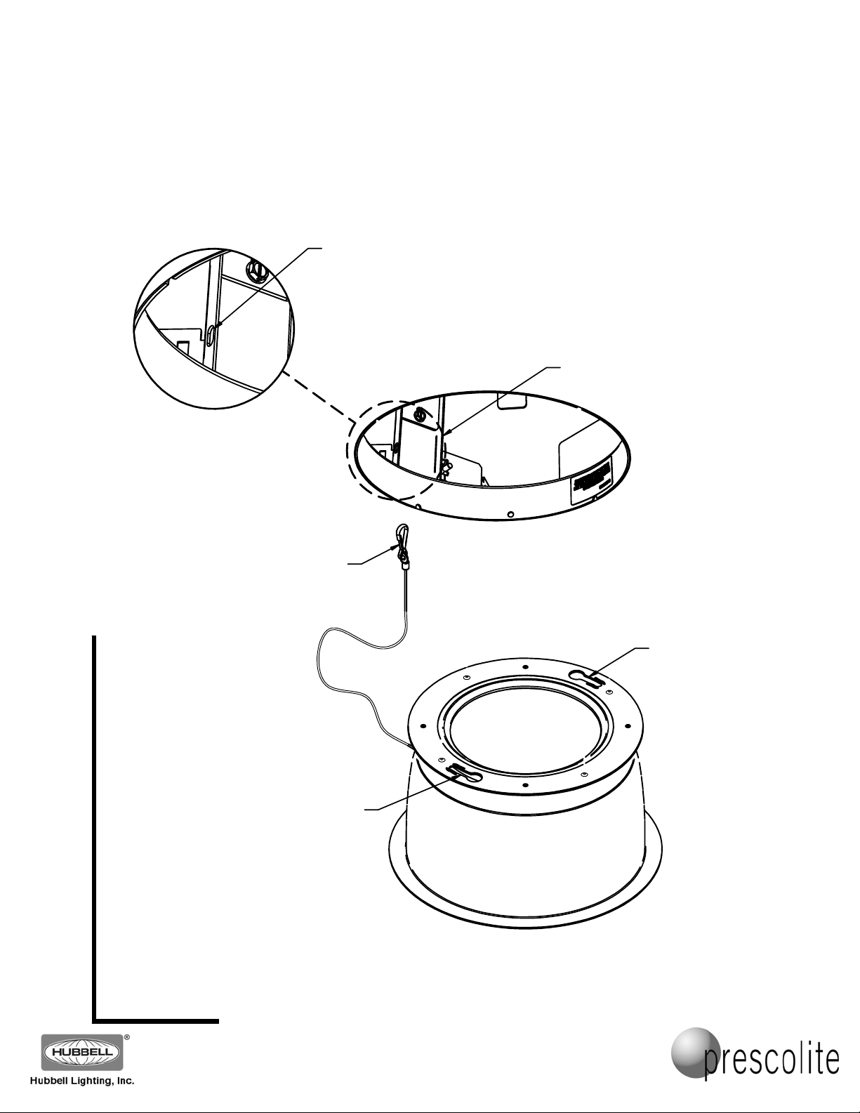
10. Attach the reflector by first attaching the reflector tether to one of the mounting slots in the yoke riser
brackets visible through the cutout from below the ceiling (See FIG. 8)
Part No...........................................
93047835
PAGE 6 OF 7
www.prescolite.com y Prescolite Toll Free Technical Support 1.888.PRS.4TEC y Hours: 8am - 5pm ET
Sheet
REFLECTOR TETHER
MOUNTING SLOT
(ONE ON EACH
YOKE RISER BRACKET)
YOKE RISER BRACK ET
(ONE ON EACH SIDE)
DETAIL
REFLECTOR TETHER
(9L/12L 55 DEG OPEN
REFLECTOR SHOWN)
REFLECTOR
KEYHOLE
SLOT
701 Mille nnium Blvd• Greenville, SC 29607
With representatives offices in principal cities throughout North America.
Copyright , revision, All Rights Reserved - Printed in U.S.A.
2013 04/12/13
REFLECTOR
KEYHOLE
SLOT
FIG.8
Page 7
Instruction
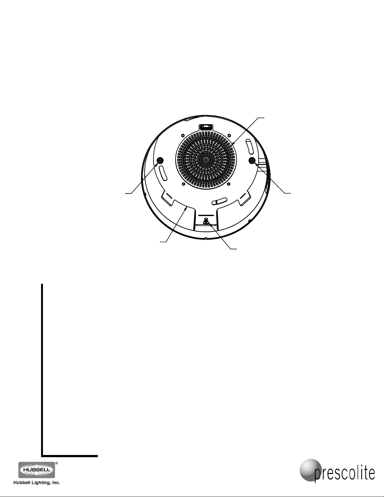
11. Once the tether is attached, push the tether cable up into the ceiling, away from the LEDs, while
slowly raising the reflector into the ceiling opening. It will make it easier to install the reflector if
the keyhole slots in the reflector top flange are generally lined up in the same location as the
reflector mounting buttons on the light engine, visible from below the ceiling on the yoke bracket
on either side of the LED circuit board (See FIG. 8 & FIG. 9).
Sheet
12. Push the reflector into the fixture until it contacts the light engine yoke and rotate it slightly from
side to side until the reflector mounting buttons fit into the open holes in the keyhole slots on the
reflector. Once these buttons are in the keyhole slots, push up on the reflector to seat it against
the light engine, and rotate the reflector clockwise until the buttons lock into the spring detents at
the ends of the keyhole slots. A slight click will be heard/felt when the reflector is properly locked
to each reflector mounting button on the light engine. If the reflector flange is not flush with the
ceiling after installation, or if the keyhole slots are difficult to line up, the light engine yoke may
need to be checked for proper attachment location, or the reflector upper flange may need to be
straightened if it was accidentally bent. There is enough flexibility in the light engine yoke
mounting slots so the location can be finely adjusted up or down if the need arises.
REFLECTOR
MOUNTING
BUTTON
LIGHT
ENGINE
YOKE
FIG. 9
Part No...........................................
LEDs
REFLECTOR
LIGHT ENGINE YOKE
ADJUSTMENT SCREW
(ONE OF TWO)
93047835
PAGE 7 OF 7
www.prescolite.com y Prescolite Toll Free Technical Support 1.888.PRS.4TEC y Hours: 8am - 5pm ET
MOUNTING
BUTTON
KEEP THESE INSTALLATION INSTRUCTIONS!
701 Mille nnium Blvd• Greenville, SC 29607
With representatives offices in principal cities throughout North America.
Copyright , revision, All Rights Reserved - Printed in U.S.A.
2013 04/12/13
 Loading...