

Page 1
1
2
3
4
5
InstructionSheet
InstructionSheet
IMPORTANT SAFETY INFORMATION. READ AND FOLLOW ALL SAFETY INSTRUCTIONS. Follow label information and
instructions concerning Wet or Damp Locations, installation near combustible materials, insulation, building materials, and
proper lamping. Do not install in areas subject to combustible vapors or gases. Before wiring to power supply and during
servicing or relamping, turn off power at fuse or circuit breaker. All servicing or relamping must be performed by
qualified service personnel. Product must be grounded to avoid potential electric shock or other potential hazard. Product must be mounted in locations and at heights and in a manner consistent with its
intended use, and in compliance with the National Electrical Code and local codes. The use of accessory
equipment not recommended by the manufacturer or installed contrary to instructions may cause an unsafe condition. Do
not block light emanating from product in whole or part, as this may cause an unsafe condition. Do not allow items such
as drapes, curtains, screens or the like to come into contact with the product or to block light from the product, as this may
cause an unsafe condition.
WARNING - This product contains chemicals known to the State of California to cause cancer, birth defects and/or other
reproductive harm. Thoroughly wash hands after installing, handling, cleaning, or otherwise touching this product.
LITEFRAME
Part No. . . . . . . . . . . . . . . . . . . . . . . . . . . . . 93028790
INSTALLATION INSTRUCTIONS
®
LF6LED/LF8LED AND 6LFLED/8LFLED
www.prescolite.com • Prescolite TollFree Technical Support 1.888.PRS.4TEC • Hours: 8am - 5pm ET
1. Install the fixture in the ceiling using the
hanger bars (supplied), or mounting
channel or bars (by others) placed in the
adjustable mounting brackets. Mount the
fixture in the ceiling so that the weight of
the fixture is supported by the hanger bars,
mounting channel, bar, and/or hanger
wires secured to the building structure.
2. Adjust the fixture so the bottom of the
plaster flange opening is flush with the
finished ceiling line and in alignment with
adjacent fixtures. Secure mounting brackets
by tightening wing nuts on either side of
the fixture.
3. Determine where the supply wiring
conduit will enter the J-Box and attach it
in conformance with the National Electric
Code.
4. Remove J-Box cover plate. Remove
appropriate knockout and assemble
appropriate connector for the supply wire
used. Connect ground wires to green
ground leads. Connect white (common) to
white (leads). Connect power supply (line)
to black lead(s). Reinstall J-Box cover.
WARNING: DO NOT pinch wires
between J-Box/ballast cover
and J-Box. Consult a qualified
electrician for all other options
that require other wiring
configurations.
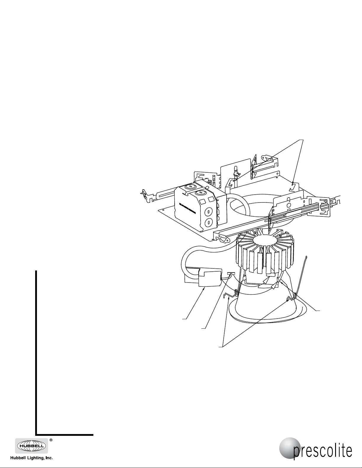
5. Pull electrical cover (1) down through
opening in fixture. (SEE FIG 1)
6. Squeeze two torsion springs (2) together
and insert ends into two brackets (3). (SEE
FIG 1)
7. Insert connector (4) into module (5) and
snap electrical cover (1) onto module
assembly. (SEE FIG 1)
8. Push trim assembly up towards ceiling until
springs draw trim firmly against ceiling.
3
FIG 1
5
1
4
2
CAUTION: DO NOT ATTEMPT TO MODIFY OR REWIRE FACTORY-INSTALLED WIRING ON THE FIXTURE. SAFETY AND
PROPER OPERATION OF THE FIXTURE DEPEND ON THE INTEGRITY OF THE WIRING.
701 Millennium Boulevard • Greenville, SC 29607
With representatives offices in principal cities throughout North America.
Copyright 2011, 4/11/11 revision, All Rights Reserved - Printed in U.S.A.
 Loading...