

Page 1
InstructionSheet
InstructionSheet
IMPORTANT SAFETY INFORMATION. READ AND FOLLOW ALL SAFETY INSTRUCTIONS. Follow label information
and instructions concerning Wet or Damp Locations, installation near combustible materials, insulation, building materials,
and proper lamping. Do not install in areas subject to combustible vapors or gases. Before wiring to power supply and
during servicing or relamping, turn off power at fuse or circuit breaker.
qualified service personnel. Product must be grounded to avoid potential electric shock or other potential hazard.
Product must be mounted in locations and at heights and in a manner consistent with its intended use, and in
compliance with the National Electrical Code and local codes. The use of accessory equipment not recommended by
the manufacturer or installed contrary to instructions may cause an unsafe condition. Do not block light emanating from
product in whole or part, as this may cause an unsafe condition. Do not allow items such as drapes, curtains, screens or
the like to come into contact with the product or to block light from the product, as this may cause an unsafe condition.
INSTALLATION INSTRUCTIONS
Part No. . . . . . . . . . . . . . . . . . . . . . . . . . . . . . . . .05282500
www.prescolite.com • Prescolite TollFree Technical Support 1.888.PRS.4TEC • Hours: 8am - 5pm ET
All servicing or relamping must be performed by
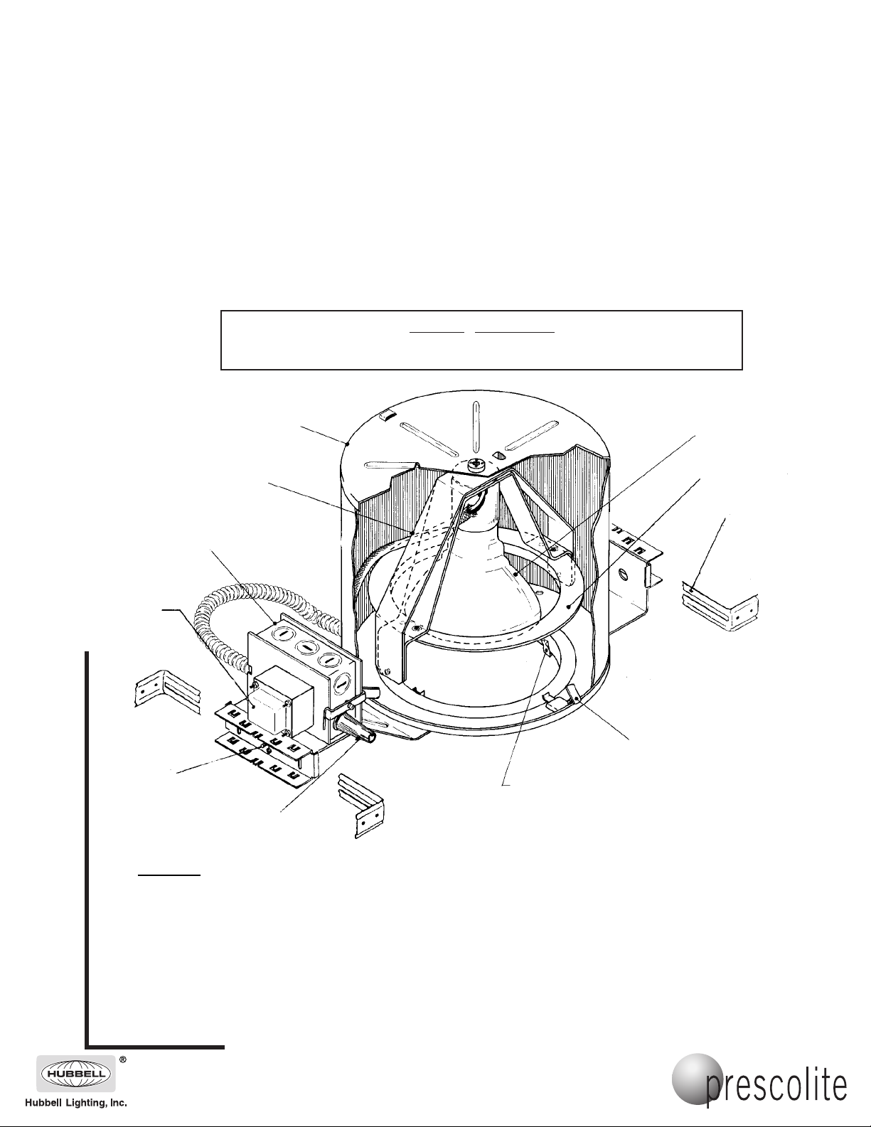
CAT NO. 1371 & 1375
Transformer
(277/120 Volt
version only)
Rotation/Pivot
Yoke
J-Box
Do not install insulation within three (3) inches of fixtures sides, wiring compartment or top of fixture
in such a manner to entrap heat.
Housing
WARNING - RISK OF FIRE:
Lamp
(by others)
Pivot
Ring
Adjustment
Adjustable
Bar Hanger
Housing Clip
Adjustment
Screw (2)
Thermal Protector
CAUTION: To avoid electrical shock, be sure power supply is turned off before installing or servicing this fixture.
1. Refer to instruction sheet No. 463 (included) to assemble the bar hangers, install
and adjust the housing.
2. Adjust the fixture so the bottom edge of the plaster flange is flush with the finished
ceiling line. Accomplish this using the adjustable screws securing the mounting
brackets on either end of the fixture.
101 Corporate Drive • Spartanburg, SC 29303
With representatives of
Copyright 2005, 08/05 revision, All Rights Reserved - Printed in U.S.A.
fices in principal cities throughout North
America.
Trim Retaining Clip (3)
Page 2
InstructionSheet
3. Remove J-Box cover plate. Remove appropriate knockout and assemble
appropriate connector for the supply wire used. Connect ground wires to green
ground leads. Connect white (common) to white (leads). Connect power supply
(line) to black lead(s). Reinstall J-Box cover.
WARNING: DO NOT pinch wires between J-Box/ballast cover and J-Box.
Consult a Qualified Electrician for all other options that require other
wiring configurations. If fusing is required, a field-installed module is
available (module is cartoned separately).
Install trim and correct lamp.
4.
Part No. . . . . . . . . . . . . . . . . . . . . . . . . . . . . . . . .05282500
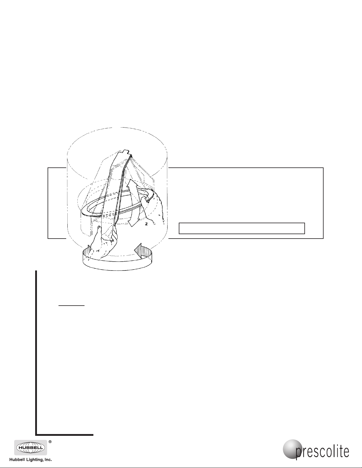
AIMING THE LAMP
Aiming can be accomplished with or without trim installed.*
1. Grasp pivot adjustment ring and rotate about center of fixture
(up to 345°).
2. While still grasping ring, push or pull ring forward or backward
until the proper lamp aiming is achieved (up to 40° in either
direction).**
*For R-40 lamp trim must be installed before aiming.
**Up to 35° in either direction for R-40 lamp.
NOTE: Use caution in aiming R-40 lamp to avoid
contact between lamp and trim ring.
www.prescolite.com • Prescolite TollFree Technical Support 1.888.PRS.4TEC • Hours: 8am - 5pm ET
CAUTION: Do not attempt to modify or rewire factory-installed wiring on the fixture. Safety and proper
operation of the fixture depend on the integrity of the wiring.
101 Corporate Drive • Spartanburg, SC 29303
With representatives of
Copyright 2005, 08/05 revision, All Rights Reserved - Printed in U.S.A.
fices in principal cities throughout North
America.
 Loading...