

Page 1

Preproofer 770/790/970/990
Installation Manual
Page 2

Digital Information Ltd.
Technoparkstrasse 1
CH-8005 Zürich
© Copyright by Digital Information Ltd. 2010
This manual is proprietary in nature and the sole property of
Digital Information. It may not be reproduced, in whole or in part,
without the express written permission of Digital Information.
Digital Information reserves the right to modify and/or delete any
material and/or capabilities described herein.
All the documentation in this manual is instructional and for the
operation of Preproofer machine. Digital Information shall not be
responsible for any damage or claims resulting from any errors or
omissions in this manual.
Owning to our policy of continuous product development,
specifications, terms and description of Preproofer 940/980 are
subject to change without prior notice.
.
Identifier Hardware Installation manual - EN
Target group Installation, Technician
Product Preproofer 770/790/970/990
Version V2.1
Date May 2012
Article code Preproofer IM7498-021 EN
Page 3

Table of contents
Preproofer x700 / x900 – HW Installation Manual I
Table of contents
1 Introduction .................................................................................................................................... 1-1
2 Safety............................................................................................................................................... 2-1
2.1 Warning ............................................................................................................................................ 2-1
3 Pre Installation Tasks..................................................................................................................... 3-2
3.1 Tools Required for the Installation .................................................................................................... 3-2
3.2 PC Specification ............................................................................................................................... 3-2
3.3 Materials Required for Installation ................................................................................................... 3-2
3.4 Unpacking ........................................................................................................................................ 3-3
4 Frame Setup ................................................................................................................................... 4-1
4.1 Overview .......................................................................................................................................... 4-1
4.2 Frame Parts...................................................................................................................................... 4-2
5 Assembly ........................................................................................................................................ 5-1
5.1 Frame Sides ..................................................................................................................................... 5-1
5.1.1 Additional Parts ................................................................................................................. 5-1
5.1.2 Mount the Base Plate for the Wheels ............................................................................... 5-2
5.1.3 Mount the Pillar and Distance Profile ............................................................................... 5-3
5.2 Mount Bracket to Frame Sides ........................................................................................................ 5-5
5.2.1 Additional Parts ................................................................................................................. 5-5
5.2.2 Mount the Brackets ........................................................................................................... 5-6
5.3 Mount Cross Member Top .............................................................................................................. 5-10
5.4 Cross Beams .................................................................................................................................. 5-10
5.4.1 Additional Parts ............................................................................................................... 5-10
5.4.2 Mount the Cross Beam for TOP Printer .......................................................................... 5-11
5.4.3 Mount the Cross Beam for BOTTOM Printer .................................................................. 5-12
5.4.4 Mount the Stabilization Cross Beams ............................................................................. 5-13
5.4.5 Tighten the Stabilization Cross Beams ........................................................................... 5-15
5.4.6 Position the Cross Beam for BACK Printer .................................................................... 5-16
5.4.7 Position the Cross Beam for FRONT Printer .................................................................. 5-17
5.5 Brackets for Fixing the Printer to the Frame .................................................................................. 5-19
5.5.1 Additional Parts ............................................................................................................... 5-19
5.5.2 Mount Brackets to Profile ................................................................................................ 5-20
5.6 Mount the Cable Channel .............................................................................................................. 5-21
5.6.1 Additional Parts ............................................................................................................... 5-21
5.7 Add the Wheels .............................................................................................................................. 5-22
5.7.1 Additional Parts ............................................................................................................... 5-22
Page 4

Table of contents
II Preproofer x700 / x900 – HW Installation Manual
5.7.2 Mount the Wheels ........................................................................................................... 5-23
6 Prepare the BACK Printer ............................................................................................................. 6-1
6.1 Remove the Paper Roll Cover ......................................................................................................... 6-1
6.1.1 Roll Cover Assembly ......................................................................................................... 6-1
6.2 Optional: Remove the Paper Roll Back Cover ................................................................................. 6-2
6.2.1 Take off the Screws .......................................................................................................... 6-2
6.3 Remove the Roll Adapter Holder and Guide .................................................................................... 6-2
6.3.1 Take off the Guide ............................................................................................................. 6-2
6.3.2 Take of the Roll Paper Adapter ......................................................................................... 6-3
6.4 Mount the Base Profile for Paper Guide / Camera holder ............................................................... 6-3
6.4.1 Additional Parts ................................................................................................................. 6-3
6.4.2 Mount the Profile ............................................................................................................... 6-4
6.4.3 Optional: Take off the Black Side Cover ........................................................................... 6-5
6.5 Set the Wires .................................................................................................................................... 6-5
6.5.1 Additional Parts ................................................................................................................. 6-5
6.5.2 Open PCB Cover on the Epson Printer ............................................................................ 6-7
6.5.3 Cable from Electronic Box ................................................................................................ 6-7
6.6 CUT MOTOR Setup ......................................................................................................................... 6-8
6.6.1 Remove the CUT Motor Cable ......................................................................................... 6-8
6.7 PAPER FEED Motor Setup .............................................................................................................. 6-9
6.7.1 Take Off the Paper Feed Motor Cable .............................................................................. 6-9
6.8 CUT MOTOR ENCODER Setup - Electronic Box - HW Release 2 ............................................. 6-11
6.9 Take Off the End Switch and Encoder Cable ................................................................................. 6-11
6.9.1 Take Off and Reconnect the End Switch and Encoder Cable ........................................ 6-11
6.10 Wire the Control Panel Back Printer .............................................................................................. 6-13
6.10.1 Remove the Control Panel.............................................................................................. 6-13
6.10.2 Solder the Wires to the Panel ......................................................................................... 6-13
6.10.3 Guide the Cable to the Electronic Box ............................................................................ 6-15
7 Prepare the FRONT Printer ........................................................................................................... 7-1
7.1 Wire the Control Panel Front Printer ................................................................................................ 7-1
7.1.1 Take off the Control Panel ................................................................................................ 7-1
7.1.2 Solder the Wires to the Panel ........................................................................................... 7-1
7.1.3 Guide the Cable to the Electronic Box .............................................................................. 7-3
8 Set the Printers into the Stand ...................................................................................................... 8-1
8.1.1 Additional Parts ................................................................................................................. 8-1
8.2 Back Printer ...................................................................................................................................... 8-2
8.3 Front Printer ..................................................................................................................................... 8-4
9 Paper Guide / Camera System ...................................................................................................... 9-1
9.1 Side parts - Step 1 ............................................................................................................................ 9-1
Page 5

Table of contents
Preproofer x700 / x900 – HW Installation Manual III
9.1.1 Parts used ......................................................................................................................... 9-1
9.1.2 Assembly .......................................................................................................................... 9-2
9.2 Side Parts - Camera Holder BACK Printer ...................................................................................... 9-3
9.2.1 Parts used ......................................................................................................................... 9-3
9.2.2 Assembly .......................................................................................................................... 9-4
9.3 Assembly „Right Holder“ and „Camera holder“ ................................................................................ 9-5
9.3.1 Parts used ......................................................................................................................... 9-5
9.3.2 Assembly .......................................................................................................................... 9-5
9.4 Assembly Camera Holder Front Printer ........................................................................................... 9-6
9.4.1 Parts used ......................................................................................................................... 9-6
9.4.2 Assembly .......................................................................................................................... 9-7
9.5 Mount Side Holder Parts to BACK printer ........................................................................................ 9-7
9.5.1 Additional parts ................................................................................................................. 9-7
9.5.2 Mount the side holders to Profile ...................................................................................... 9-8
9.6 Paper Guide Tubes .......................................................................................................................... 9-9
9.6.1 Additional parts ................................................................................................................. 9-9
9.6.2 Mount Paper Guide Tubes .............................................................................................. 9-10
9.7 Tube Stopper .................................................................................................................................. 9-11
9.7.1 Additional parts ............................................................................................................... 9-11
9.7.2 Mount tube stopper ......................................................................................................... 9-12
9.8 Add Slot Nuts to Profile Front Printer ............................................................................................. 9-12
9.8.1 Additional Parts ............................................................................................................... 9-12
9.8.2 Mount to Profile ............................................................................................................... 9-13
9.9 Add Paper Guide and Paper Tension Parts ................................................................................... 9-14
9.9.1 Additional Parts ............................................................................................................... 9-14
9.9.2 Mount Paper Guide Tube Front Printer .......................................................................... 9-15
9.9.3 Mount the Paper Tension Guide ..................................................................................... 9-16
9.10 Camera and Bar Light on Back Printer .......................................................................................... 9-17
9.10.1 Additional Parts ............................................................................................................... 9-17
9.10.2 Mount Camera and LED Bar Light ................................................................................. 9-19
9.11 Camera and Bar Light on Front Printer .......................................................................................... 9-19
9.11.1 Additional Parts ............................................................................................................... 9-19
9.11.2 Mount LED Bar Light to holder ....................................................................................... 9-20
9.11.3 Mount the holder to Front printer .................................................................................... 9-20
9.11.4 Mount the Camera .......................................................................................................... 9-21
9.12 Paper Bow for Back Printer ............................................................................................................ 9-21
9.12.1 Additional Parts ............................................................................................................... 9-21
9.12.2 Assembly ........................................................................................................................ 9-22
9.12.3 Assembly to the Profile ................................................................................................... 9-23
9.13 Paper Bow for Front Printer ........................................................................................................... 9-23
9.13.1 Additional Parts ............................................................................................................... 9-23
9.14 Mount the Electronic Box ............................................................................................................... 9-25
Page 6

Table of contents
IV Preproofer x700 / x900 – HW Installation Manual
9.15 Align the Printers ............................................................................................................................ 9-25
9.15.1 Paper Path ...................................................................................................................... 9-25
9.15.2 Parallel Alignment Front Printer ...................................................................................... 9-27
9.15.3 Parallel Alignment Back Printer ...................................................................................... 9-30
9.15.4 Horizontal Alignment ....................................................................................................... 9-31
10 Printer Panel Configuration ...................................................................................................... 10-32
10.1 Parameter Setup TOP and BOTTOM printer ............................................................................... 10-32
10.1.1 TOP Printer - Configure Custom Paper 1 ..................................................................... 10-33
10.1.2 Bottom Printer- Configure Custom Paper 1 .................................................................. 10-37
11 LED Bar Light ............................................................................................................................... 11-1
11.1 Power Supply Setup for LED Bar Light .......................................................................................... 11-1
12 Setup Electronic Box – HW Revision 2 – Nov 2011 .................................................................. 12-3
12.1 HW Changes .................................................................................................................................. 12-3
12.2 Power Supply Setup for Electronic Box ......................................................................................... 12-3
12.3 Setup the Lantronix Device ............................................................................................................ 12-4
12.4 Run the Test Program .................................................................................................................... 12-4
12.5 Calibrate the CUT Motor Parameter .............................................................................................. 12-6
12.5.1 Calibration – Step by Step .............................................................................................. 12-6
12.5.2 Setup Motor Speed ......................................................................................................... 12-9
13 Setup Electronic Box – HW Revision 1 – OLD STYLE ........................................................... 13-10
13.1 Power Supply Setup for Electronic Box ....................................................................................... 13-10
13.2 Setup the Lantronix Device .......................................................................................................... 13-11
13.3 Run the Test Program .................................................................................................................. 13-11
13.4 Setup the CUT parameters .......................................................................................................... 13-12
14 Test Printer Panel Cable Connection ......................................................................................... 14-1
14.1 Test „Paper Down BACK“............................................................................................................... 14-1
14.2 Test „Pause BACK“ ........................................................................................................................ 14-1
14.3 Test „Pause FRONT“ ...................................................................................................................... 14-2
14.4 Test Paper MOVE .......................................................................................................................... 14-2
15 Calibrate Paper Movement Printer Back.................................................................................... 15-1
15.1 Background .................................................................................................................................... 15-1
15.2 Paper Traction Calibration ............................................................................................................. 15-1
Page 7

Introduction
Warning
1
Preproofer x700 / x900 – HW Installation Manual 1-1
1 Introduction
The Preproofer x900 is a fully automatic system printing double-sided imposition proofs. The system is
based on two Epson Stylus 9700/9900/9890 printing engines printing 43” wide.
The Preproofer x700 is a fully automatic system printing double-sided proofs. The system is based on two
Epson Stylus 7700/7900/7890 printing engines printing 23 wide”.
Please note:
Installation of this equipment must be done by a trained technician.
Do NOT leave Epson Printers on the stand without securing them with the Printer locking devices.
Page 8

Page 9

Safety
Warning
2
Preproofer x700 / x900 – HW Installation Manual 2-1
2 Safety
This section provides important safety information and must be read before switching on or
operating the equipment.
2.1 Warning
All precautions mentioned in this document must be strictly observed at all times. Personnel MUST therefore
read the contents of the document BEFORE commencing any work on the equipment described in the
document.
Improper use of controls and switches, failure to comply with warnings, and the performance of adjustments
or procedures not specified in this document may expose personnel to danger.
Installation of this equipment must be done by a trained technician.
Do NOT leave Epson Printers on the stand without securing them with the Printer locking devices.
Page 10

3
Pre Installation Tasks
Tools Required for the Installation
3-2 Preproofer x700 / x900 – HW Installation Manual
3 Pre Installation Tasks
3.1 Tools Required for the Installation
Standard screw driver set
Allen key set
Phillips screw driver set
Measurement tape
Cordless drill to unpack the boxes
3.2 PC Specification
CPU Intel Core 2 Quad, 2.x GHz (high performance CPU is recommended
min. 2 GB RAM
min. 1x 250 GB hard disk drive, 7200rpm
1x 64 GB Solid State Drive
min. 4x USB ports
2x Ethernet ports
19” TFT monitor (touch screen is recommended)
Windows XP or Windows 7, 32 bit version
The PC needs to be equipped with a SSD
Drive (min 64GB). The SSD drive is used
because it’s astonishing write performance
on small files as DI-Pilot does it when
communicating between the two Epson
printers, electronic box and the cameras
system.
3.3 Materials Required for Installation
For the setup, prepare the following cables / hubs which are not part of the shipment:
4x RJ45 Ethernet Cable. Length: 2m, 2m, 3m, 5m
1x Ethernet Switch 10/100/100 min. 4 Ports
Page 11

Pre Installation Tasks
Unpacking
3
Preproofer x700 / x900 – HW Installation Manual 3-3
2x shielded USB 2.0 cable, USB-mini B to USB-A,
used for camera connection, min 2 meters, goes to USB Hub
1x shielded USB 2.0 cable, USB-A to USB-B,
used for connecting the USB HUB with the PC
1x active USB Hub (runs with a Power Supply),
connects to the two USB cameras and the PC
1x Power Outlet Strip with minimum 6 outlets
used for 2x Printers, 2x DC Power Supply (Camera and Electronic Box),
1x USB Hub, 1x Ethernet Switch
3.4 Unpacking
Make sure all parts are available after unpacking the cases. Check the part list inside the shipment.
All packaged items must be inspected at the customer's site before unpacking begins. The following steps
are taken when there has been damage:
1.) Record the observations on the delivery documentation.
2.) Inform the carrier, shipping agent and insurance agent.
Units may be removed from their box only by an approved engineer or representative. Do not proceed with
unpacking when there has been a damage report until authorized by the shipping and insurance agents.
Page 12

Page 13
Frame Setup
Overview
4
Preproofer x700 / x900 – HW Installation Manual 4-1
4 Frame Setup
4.1 Overview
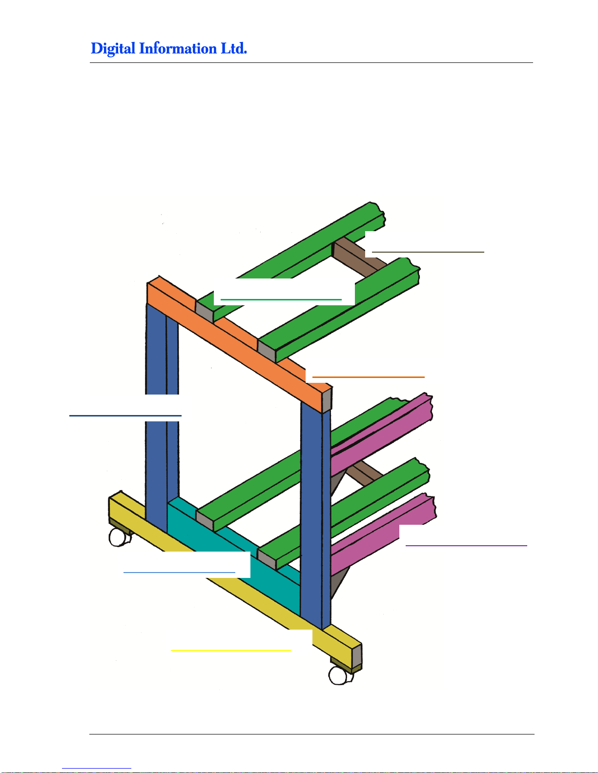
Pos 2 - 795mm
Pos 1 - 2060mm
Pos 5 - 810mm
Pos 3 - 1100mm
Pos 6 - 1980mm
Pos 4 - 650mm
Pos 8 - 305mm
Page 14

4
Frame Setup
Frame Parts
4-2 Preproofer x700 / x900 – HW Installation Manual
4.2 Frame Parts
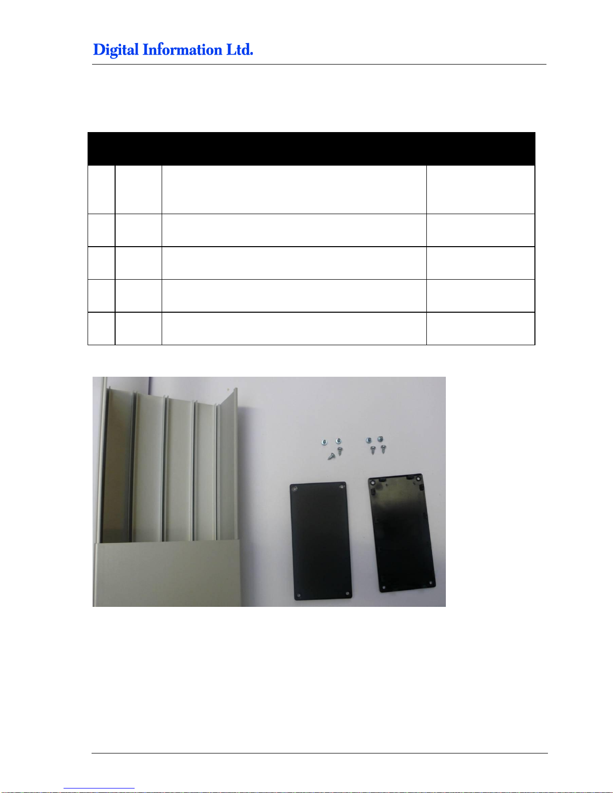
Pos Amount
Color
Name
Profile in mm
Length in mm
1 4 Cross-member for printer top /
bottom
40 x 80
2060
2 4 Pillar
40 x 80
795
3 2 Cross-member, 2 wheels mounted
40 x 80
1100
4 2 Cross-member bottom, distance
holder for lower printer
40 x 120
650
5 2 Cross-member top
40 x 80
810
6 2 Cross-member for frame
stabilization
40 x 80
1980
7 4 Distance holder for cross-member,
position 1. Also used to fix printer to
stand with bracket, position 27
40 x 40
305
8 4 Bracket for stabilization crossmember
9 4 Base plate for swivel caster
40 x 80
10
4
Swivel caster, 75mm
Page 15

Frame Setup
Frame Parts
4
Preproofer x700 / x900 – HW Installation Manual 4-3
Page 16

Page 17
Assembly
Frame Sides
5
Preproofer x700 / x900 – HW Installation Manual 5-1
5 Assembly
5.1 Frame Sides
5.1.1 Additional Parts
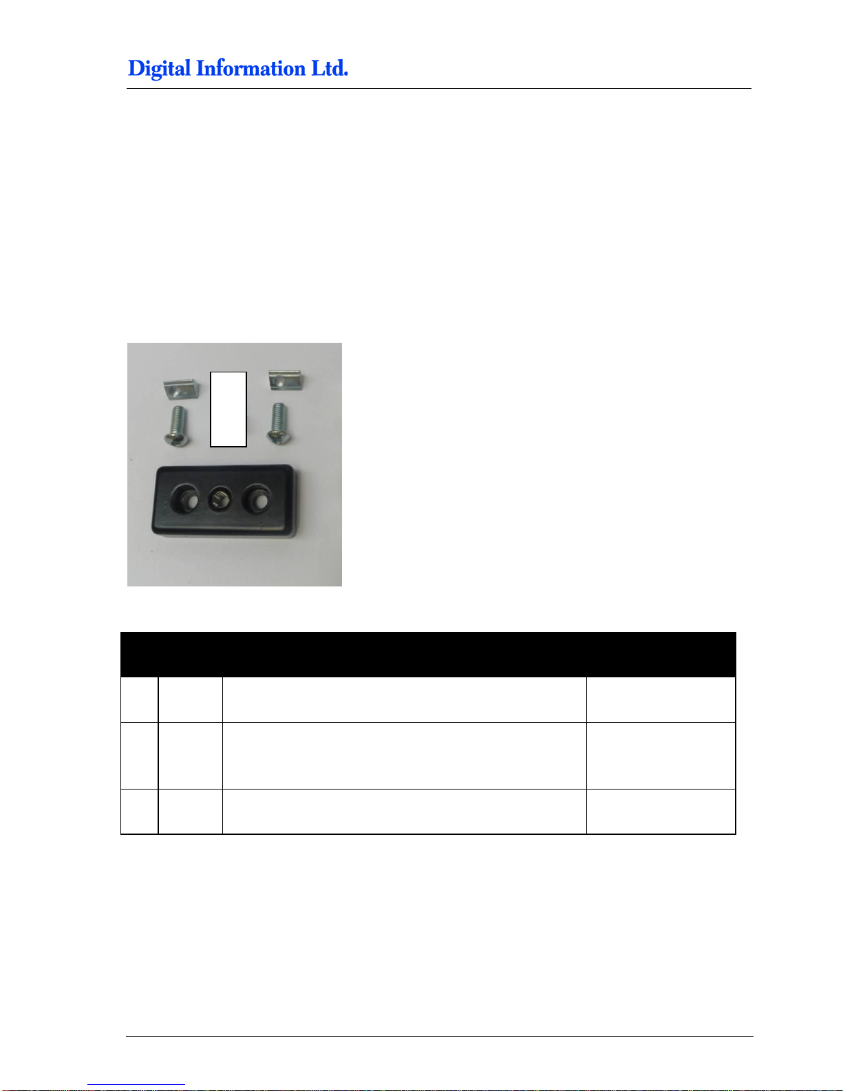
Locate the following parts:
Pos Amount
Name
Dimension in mm
23
4 Base plate for swivel caster
40 x 80
25
8
Allen screw with rounded head,
Fixes base plate to profile
M8 x 20
26
8 Slot nut
M8
Page 18
5
Assembly
Frame Sides
5-2 Preproofer x700 / x900 – HW Installation Manual
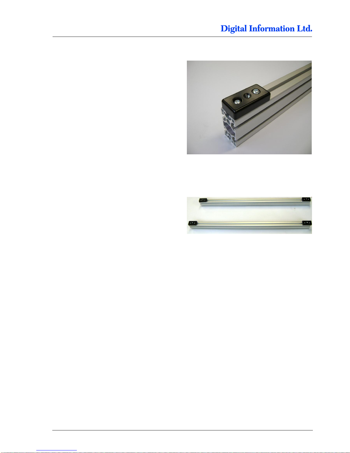
5.1.2 Mount the Base Plate for the Wheels
Mount on each side on profile (Pos 3, yellow
colored, 1100 mm) the base plates for the wheels.
Tighten them strong.
Page 19
Assembly
Frame Sides
5
Preproofer x700 / x900 – HW Installation Manual 5-3
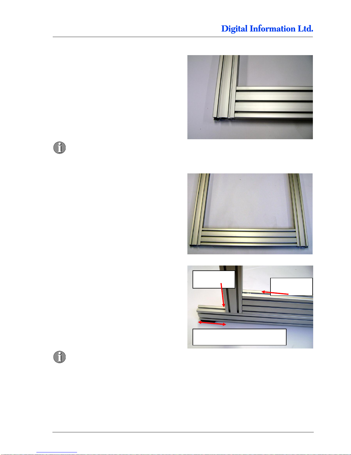
5.1.3 Mount the Pillar and Distance Profile
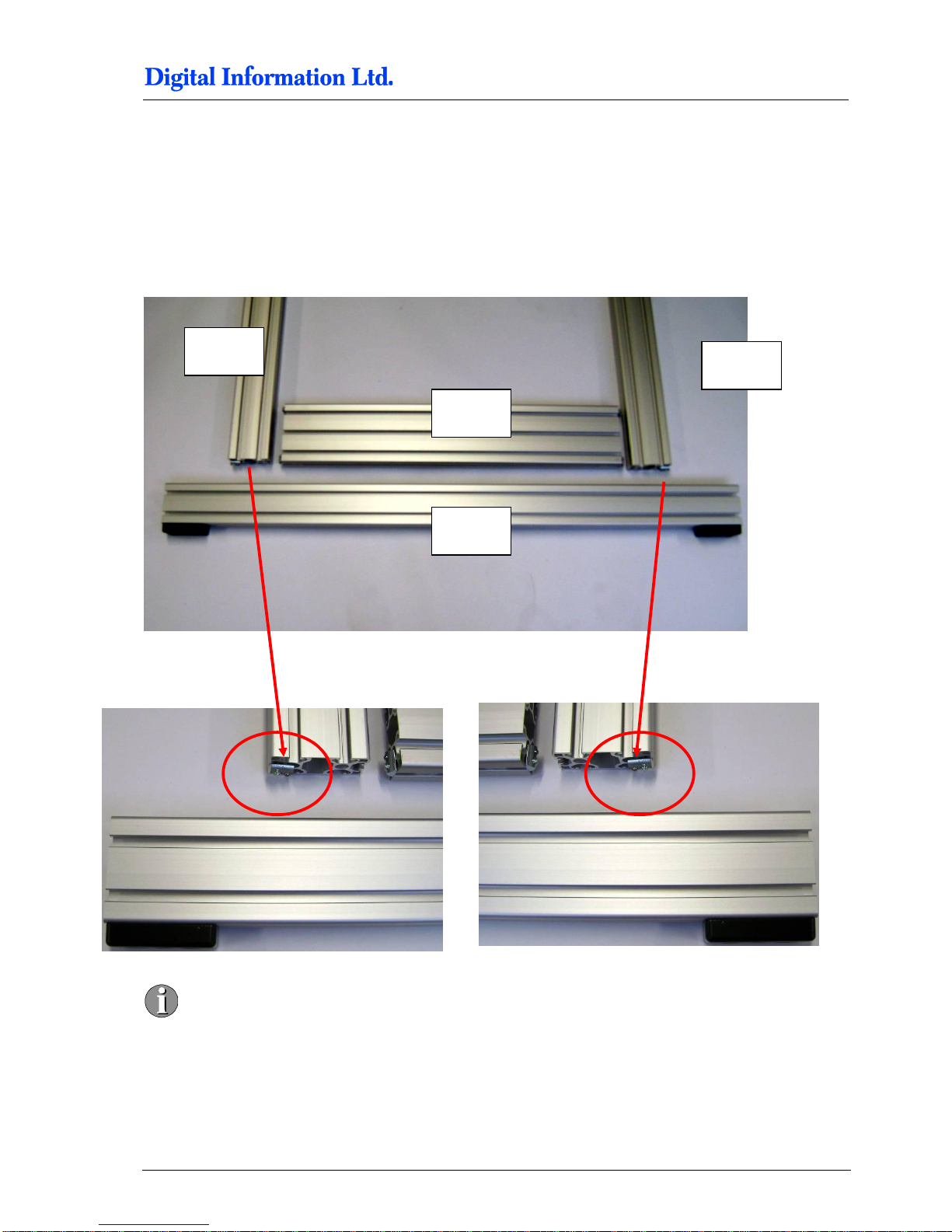
Take for each side the two pillar profiles (Pos 2, blue
colored, 795 mm) and the distance holder profile for
lower printer (Pos 4, blue colored, 650 mm, 160 mm
height).
Take care to mount the pillars correctly. The
screw is on the outer side.
Pos 4
Pos 2
Pos 2
Pos 3
Page 20
5
Assembly
Frame Sides
5-4 Preproofer x700 / x900 – HW Installation Manual
Mount first the profile Pos. 4 to the two pillars Pos.
2.
Don’t tighten too much as the profile
Pos 4 should be still sliding.
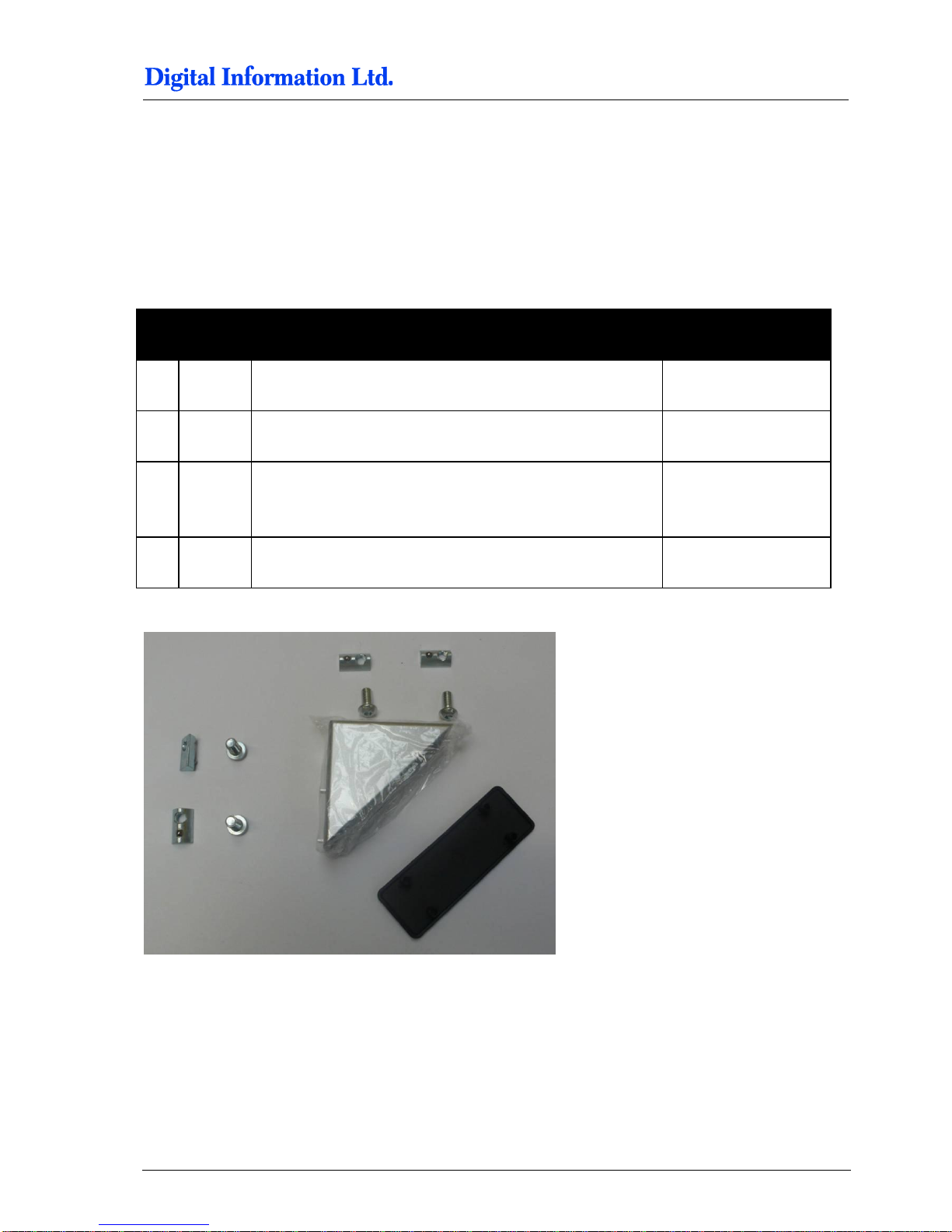
Frame look after mounting the pillars.
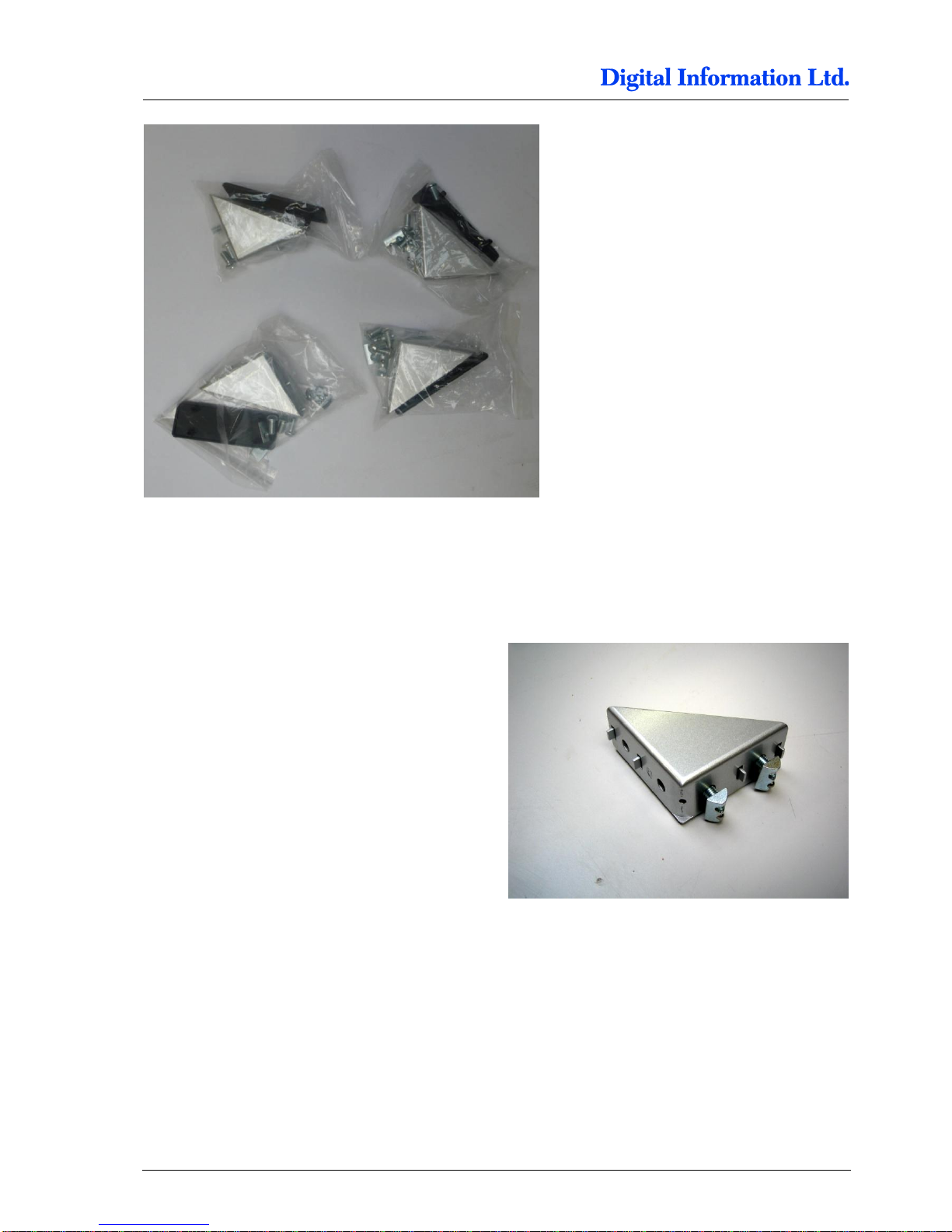
Now slide in the Profile Pos 3. The distance from
edge to the pillar is 145 mm.
FIRST tighten the screws from profile Pos 2.
SECOND tighten the screws from profile
Pos 4.
Important:
The profile Pos 4 lies PRECISLY FLAT
on top of profile Pos 3 to ensure a correct
alignment to printer top.
Distance edge to profile is 145 mm
Screw Pos 2
Screw Pos 4
Page 21
Assembly
Mount Bracket to Frame Sides
5
Preproofer x700 / x900 – HW Installation Manual 5-5
5.2 Mount Bracket to Frame Sides
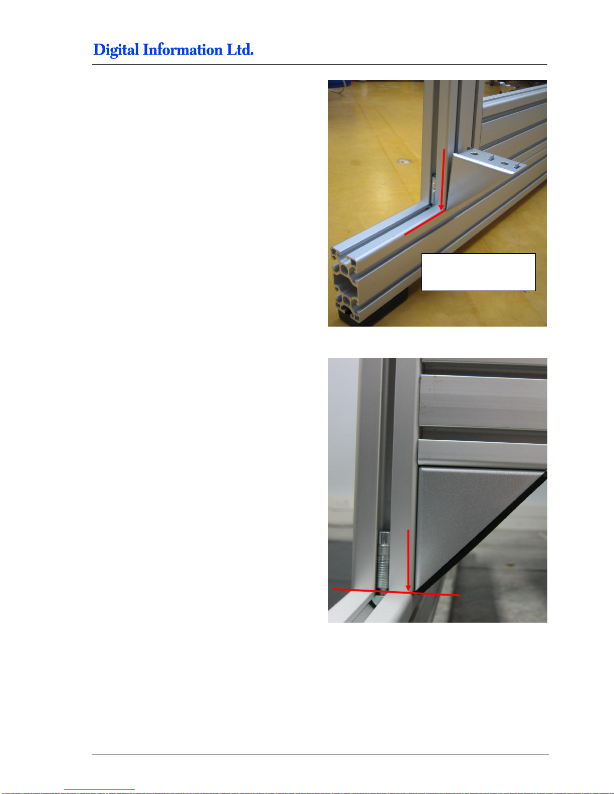
5.2.1 Additional Parts
Locate the following parts:
Pos Amount
Name
Dimension in mm
33 4
Bracket for the “stabilization cross-member” Pos 6
80 x 80
34
4 Cover, black
112 x 40
35
16 Allen screw with rounded head,
Fixes base plate to profile
M8 x 16
36
16
Slot nut
M8
.
Page 22
5
Assembly
Mount Bracket to Frame Sides
5-6 Preproofer x700 / x900 – HW Installation Manual
5.2.2 Mount the Brackets
Setup each bracket with two screws and nuts.
Page 23
Assembly
Mount Bracket to Frame Sides
5
Preproofer x700 / x900 – HW Installation Manual 5-7
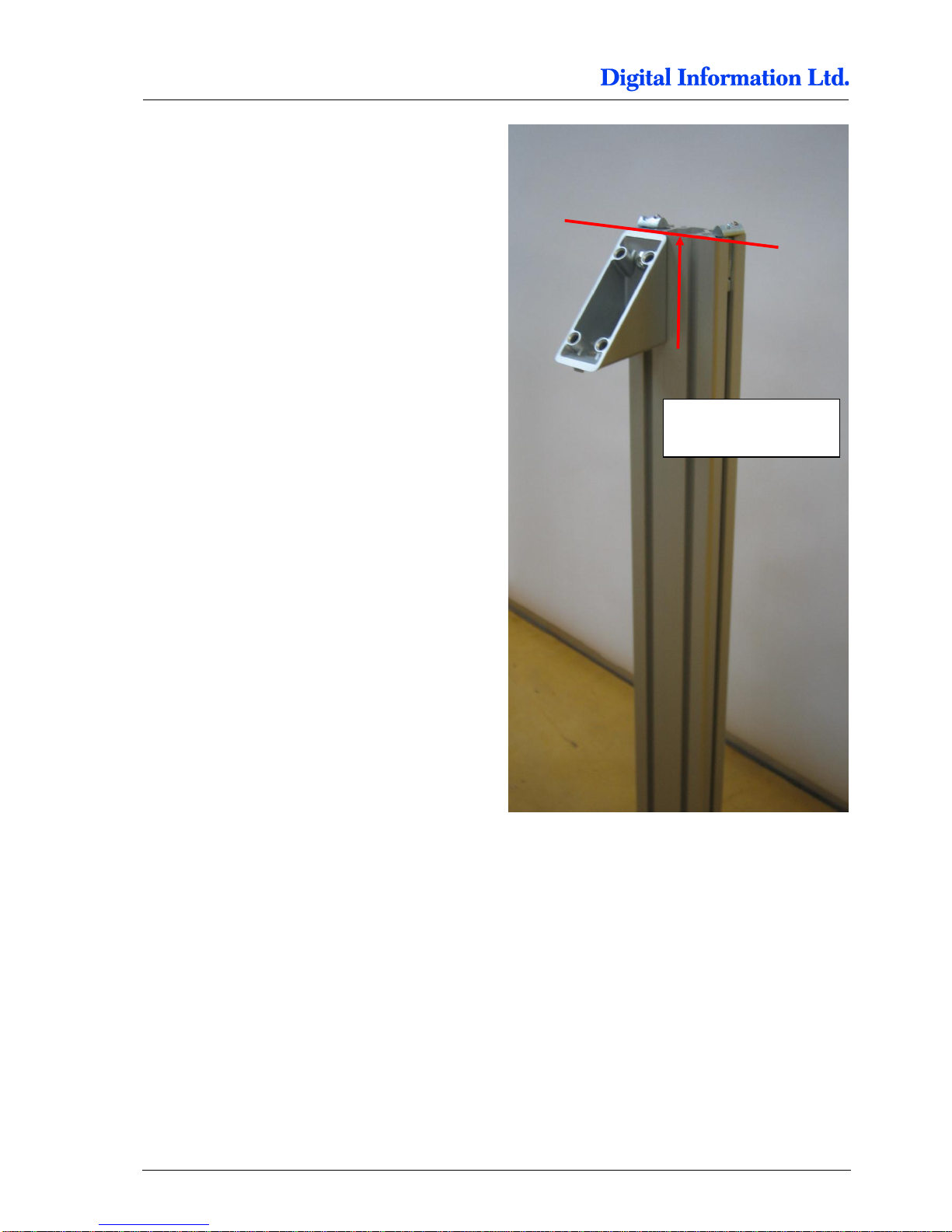
Slide in the bracket for the lower stabilization profile
like shown.
Line it up precisely with the profile edge and tighten
up strongly.
Line it up precisely with
the pillar profile edge
Page 24
5
Assembly
Mount Bracket to Frame Sides
5-8 Preproofer x700 / x900 – HW Installation Manual
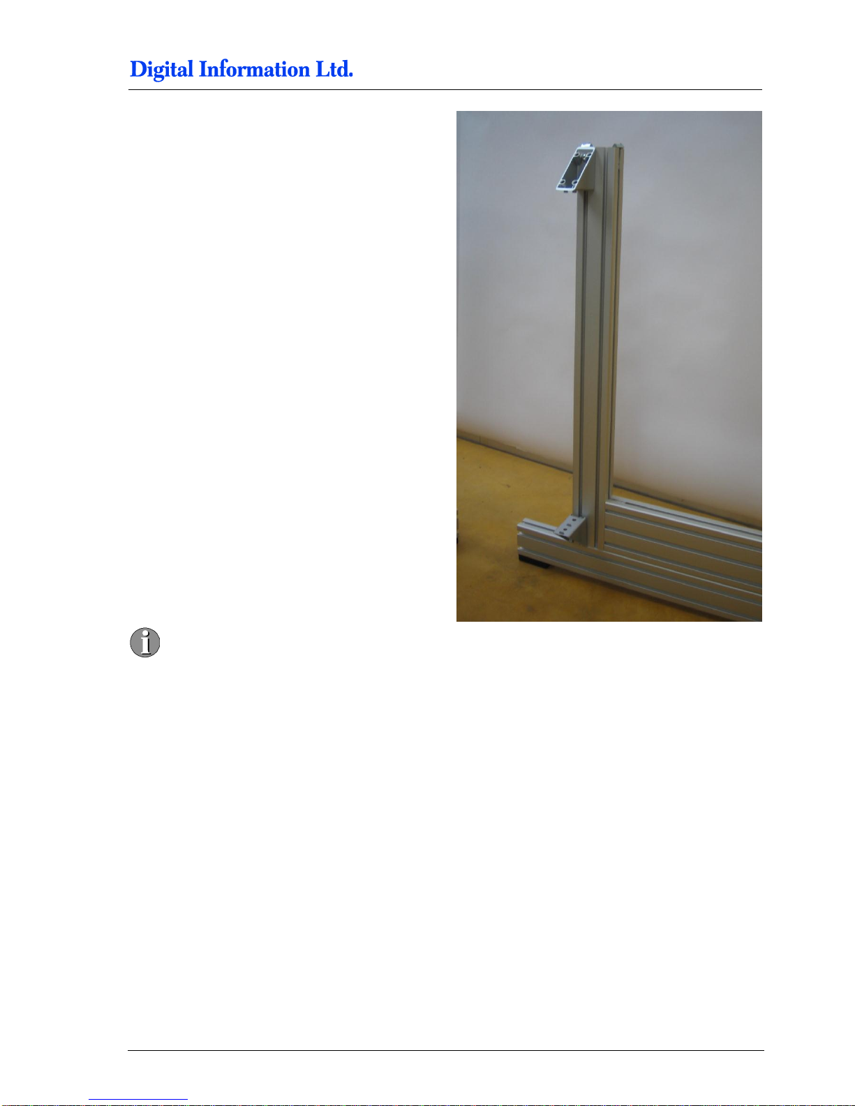
Slide in the bracket for the top stabilization profile
like shown.
Line it up precisely with the profile edge and tighten
up strongly
Line it up precisely with
the profile edge
Page 25
Assembly
Mount Bracket to Frame Sides
5
Preproofer x700 / x900 – HW Installation Manual 5-9
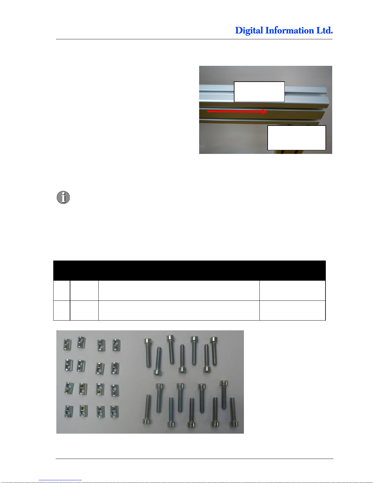
On the two frame sides, the brackets are
mounted mirrored to hold the stabilization
profile.
Page 26
5
Assembly
Mount Cross Member Top
5-10 Preproofer x700 / x900 – HW Installation Manual
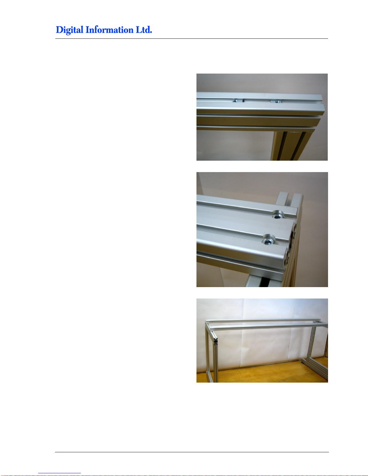
5.3 Mount Cross Member Top
On both sides, shift the profile Pos 5 into the pillar
profiles.
5.4 Cross Beams
Don’t fix the screws tightly until the manual
recommends it. The profiles should be still
moveable until the frame is fixed finally!
5.4.1 Additional Parts
Locate the following parts:
Pos Amount
Name
Dimension in mm
37 16
Allen screw, fixing Cross-member for printer top / bottom,
Pos 1
M8 x 40
38
16
Slot nut
M8
Pos 5
Pillar Pos 2
Page 27
Assembly
Cross Beams
5
Preproofer x700 / x900 – HW Installation Manual 5-11
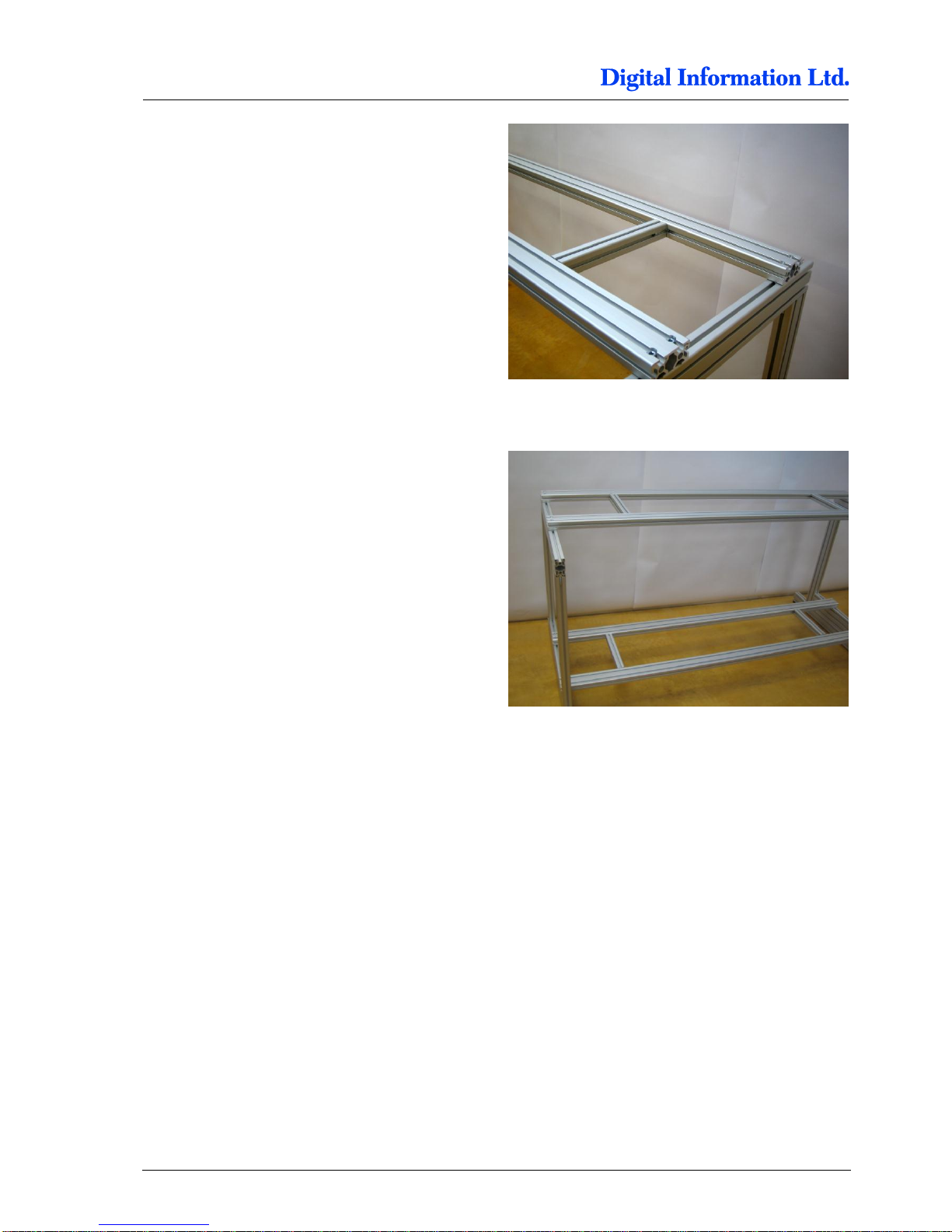
5.4.2 Mount the Cross Beam for TOP Printer
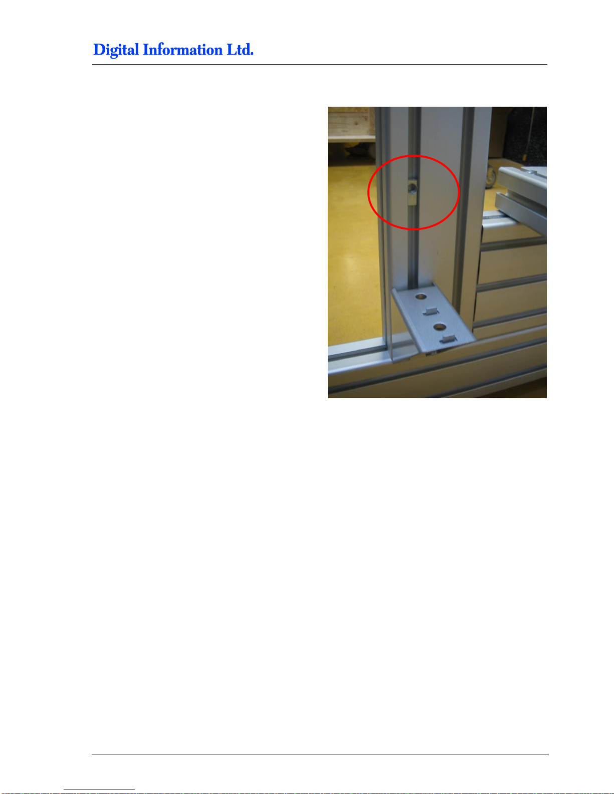
Slide on the top profile (Pos 5) four M8 slot nuts
Put the two cross beams (Pos 1, green colored,
2105 mm) on it. Check that the notch for the screw
head is on top. Use for each side two M8 screws to
fix the cross beam to profile Pos 5.
Frame with mounted cross beams for printer top.
Page 28
5
Assembly
Cross Beams
5-12 Preproofer x700 / x900 – HW Installation Manual
Mount the profile (Pos 8, brown colored, 305 mm)
between the two cross beams.
5.4.3 Mount the Cross Beam for BOTTOM Printer
Slide on the top profile (Pos 5) four M8 slot nuts on
each side.
Put the two cross beams (Pos 1, green colored,
2105 mm) on it. Check that the notch for the screw
head is on top. Use for each side two M8 screws to
fix the cross beam to profile Pos 5.
Mount the profile (Pos 8, brown colored, 305 mm)
between the two cross beams.
Page 29
Assembly
Cross Beams
5
Preproofer x700 / x900 – HW Installation Manual 5-13
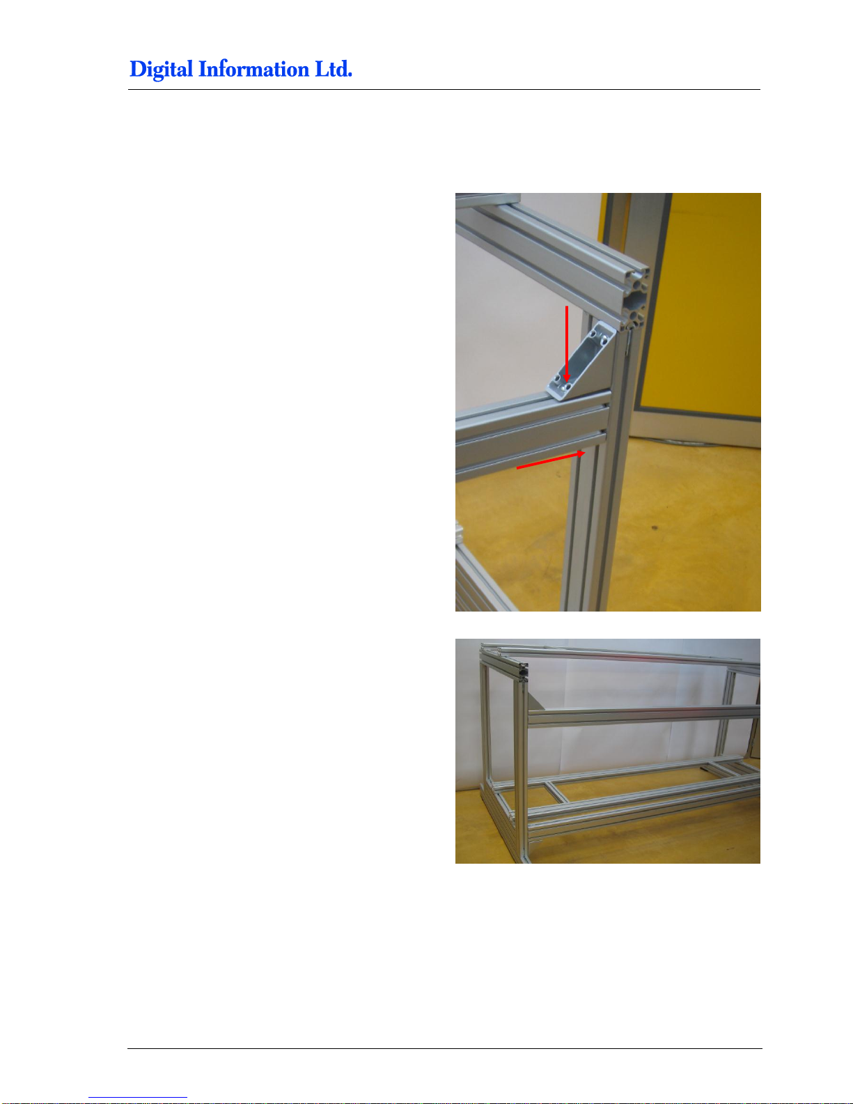
5.4.4 Mount the Stabilization Cross Beams
Slide in a M8 slot nudge on top and bottom of the
frame.
Page 30

5
Assembly
Cross Beams
5-14 Preproofer x700 / x900 – HW Installation Manual
Take the two stabilization profiles (Pos 6, purple
colored, 1980 mm)
On each side, slide in a M8 slot nudge.
Fix the stabilization profiles to the bracket and to the
profile Pos 2.
Page 31
Assembly
Cross Beams
5
Preproofer x700 / x900 – HW Installation Manual 5-15
5.4.5 Tighten the Stabilization Cross Beams
To tighten up the stabilization profiles do like:
1) Start with the top stabilization profile
2) Smoothly tighten up the two screws (shown as
red arrows) on both side of the frame
3) Check if the frame is in angle
4) Tighten now both side strongly
Page 32
5
Assembly
Cross Beams
5-16 Preproofer x700 / x900 – HW Installation Manual
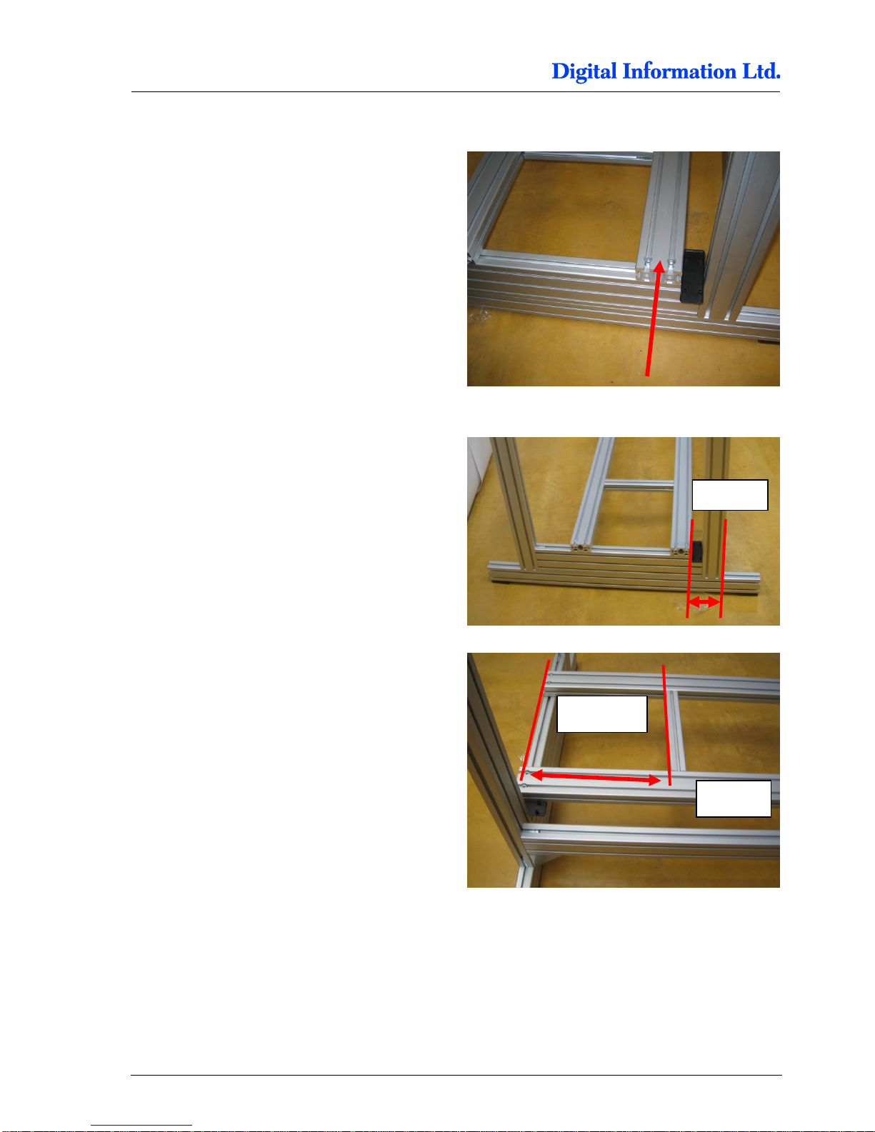
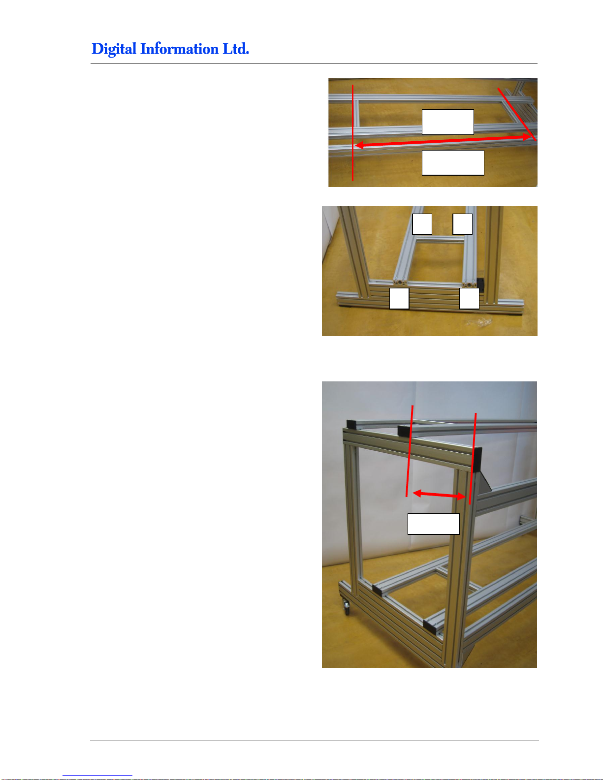
5.4.6 Position the Cross Beam for BACK Printer
Tighten first the cross beam profile for the back
printer shown on the right.
The distance between the profile Pos 2 and the
cross beam profile Pos 1 is 120mm.
Position the first distance holder (Pos 8, brown
colored, 305 mm) 395 mm from the side frame.
Fix only the screw which goes to the profile labeled
“A”.
120 mm
395 mm
Profile A
Page 33
Assembly
Cross Beams
5
Preproofer x700 / x900 – HW Installation Manual 5-17
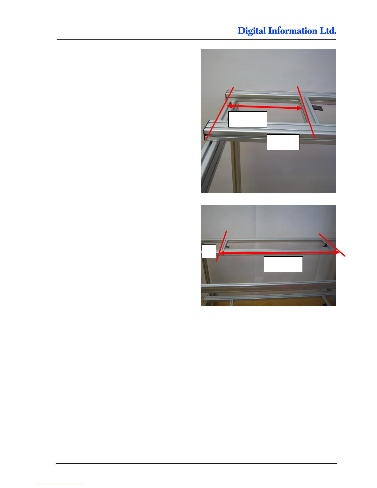
Position the second distance holder (Pos 8, brown
colored, 305 mm) 1285 mm from the first distance
holder profile.
Fix only the screw which goes to the profile labeled
“A”.
The picture shows the sequence for tighten up the
screws in the correct order.
Finalize the setup of the BACK profile by tighten the
screws from the distance holder (3)
Afterwards, tighten the screws which go to the side
frame (4).
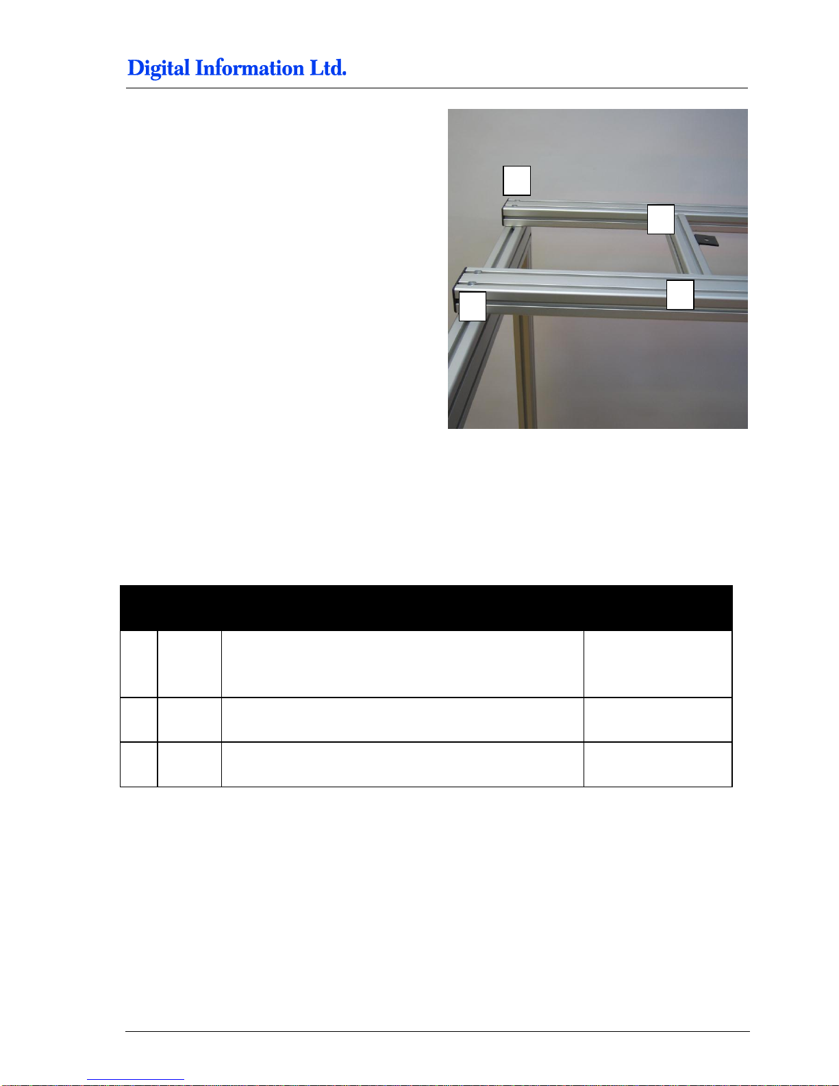
5.4.7 Position the Cross Beam for FRONT Printer
Tighten the cross beam profile for the front printer
shown on the right first.
The distance between the edge of profile Pos 5 and
the cross beam profile Pos 1 is 300mm.
Fix only the screw which goes to the profile labeled
“A”.
1285 mm
Profile A
1 2 3 4 300 mm
Page 34
5
Assembly
Cross Beams
5-18 Preproofer x700 / x900 – HW Installation Manual
Position the first distance holder (Pos 8, brown
colored, 305 mm) 340 mm from the side frame.
Fix only the screw which goes to the profile labeled
“A”.
Position the second distance holder (Pos 8, brown
colored, 305 mm) 1285 mm from the first distance
holder profile.
Fix only the screw which goes to the profile labeled
“A”.
340 mm
Profile A
1285 mm
A
Page 35
Assembly
Brackets for Fixing the Printer to the Frame
5
Preproofer x700 / x900 – HW Installation Manual 5-19
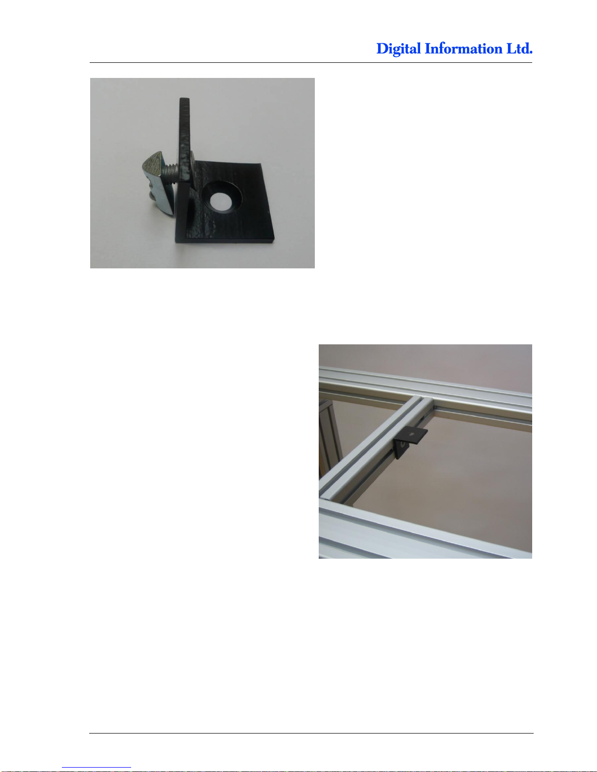
The picture shows the sequence for tighten up the
screws in the correct order.
Finalize the setup of the FRONT profile by tighten
the screws from the distance holder (3)
Afterwards, tighten the screws which go to the side
frame (4).
5.5 Brackets for Fixing the Printer to the Frame
5.5.1 Additional Parts
Pos Amount
Name
Dimension in mm
27 4
Bracket
Fixes the printers to the frame
40 x 40
28
4 Allen screw with countersunk head
M8 x 10
29
4 Slot nut
M8
1 2 3
4
Page 36
5
Assembly
Brackets for Fixing the Printer to the Frame
5-20 Preproofer x700 / x900 – HW Installation Manual
5.5.2 Mount Brackets to Profile
On the distance holder profile, mount inwards the
brackets as shown in the picture. Don’t fix the
screws to tight as they still should be movable.
Page 37
Assembly
Mount the Cable Channel
5
Preproofer x700 / x900 – HW Installation Manual 5-21
5.6 Mount the Cable Channel
5.6.1 Additional Parts
Pos Amount
Name
Dimension in mm
30 1
Cable channel
Fixes the printers to the frame
120 x 80 x 600
31
2 End cover, black
120 x 80
32
8 Pan head tapping screw
4,2 x 9,5
53 2 M5 x 12
2 Slot nut M5
Page 38
5
Assembly
Add the Wheels
5-22 Preproofer x700 / x900 – HW Installation Manual
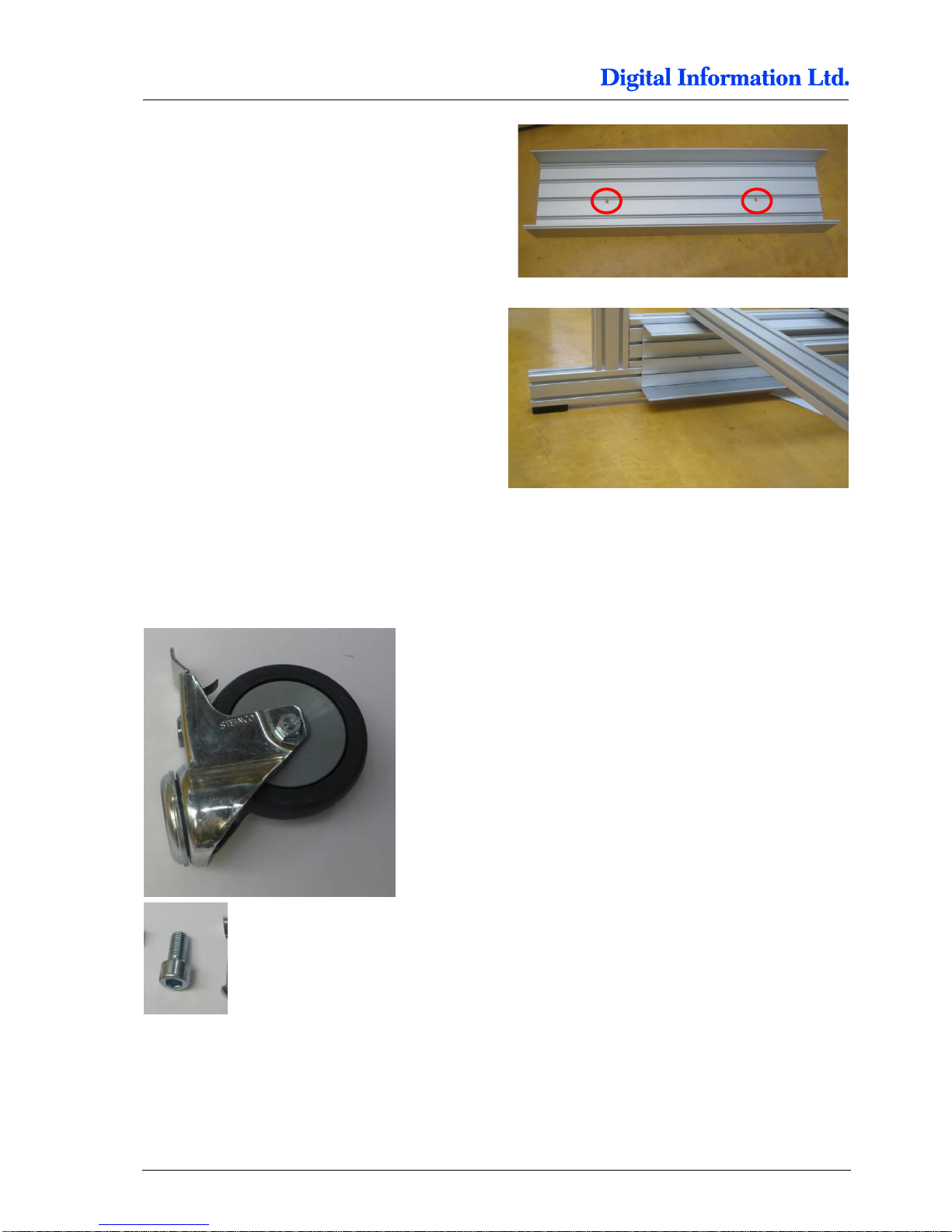
Drill two 6mm holes into cable channel.
Use two screws M5 x12 with two M5 slot nuts to fix
the channel to the frame.
5.7 Add the Wheels
5.7.1 Additional Parts
Page 39

Assembly
Add the Wheels
5
Preproofer x700 / x900 – HW Installation Manual 5-23
5.7.2 Mount the Wheels
On each side frame, mount the wheels.
Pos Amount
Name
Dimension in mm
22 4
Swivel caster with break
Wheel diameter = 75
24
4 Allen screw
Fixes swivel caster to base plate
M10 x 20
Page 40

Page 41
Prepare the BACK Printer
Remove the Paper Roll Cover
6
Preproofer x700 / x900 – HW Installation Manual 6-1
6 Prepare the BACK Printer
6.1 Remove the Paper Roll Cover
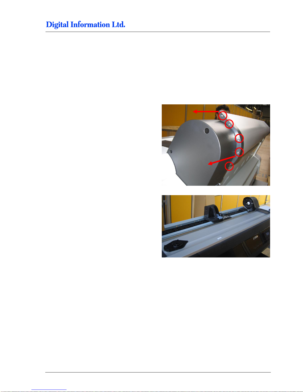
6.1.1 Roll Cover Assembly
Take the screws off on both sides of the Paper Roll
Cover.
Now spread out the two black plastic parts on both
sides to take off the aluminum Paper Roll Cover.
Page 42
6
Prepare the BACK Printer
Optional: Remove the Paper Roll Back Cover
6-2 Preproofer x700 / x900 – HW Installation Manual
6.2 Optional: Remove the Paper Roll Back Cover
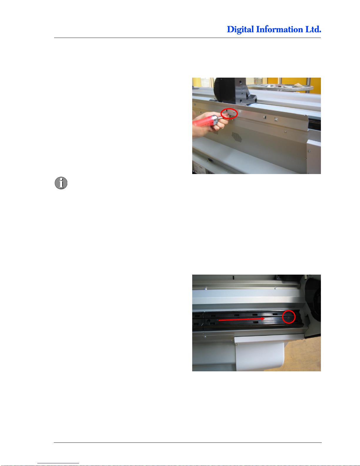
6.2.1 Take off the Screws
Take off the screws and remove the back metal
cover.
It might be a good idea to leave this angled
cover attached to the printer to use this area
to place the two rollers during the paper
load process.
6.3 Remove the Roll Adapter Holder and Guide
6.3.1 Take off the Guide
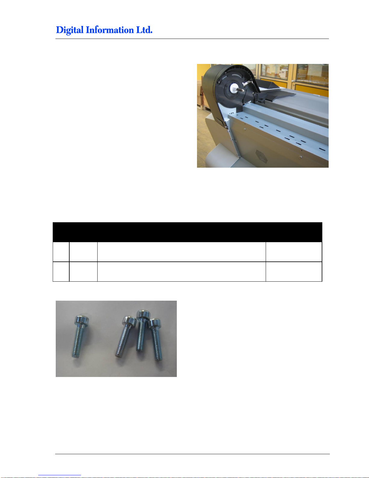
Start on the left hand side. For each guide, take off
one screw and push afterwards the guide to the left.
Page 43
Prepare the BACK Printer
Mount the Base Profile for Paper Guide / Camera holder
6
Preproofer x700 / x900 – HW Installation Manual 6-3
6.3.2 Take of the Roll Paper Adapter
Take off the roll paper adapter.
6.4 Mount the Base Profile for Paper Guide / Camera holder
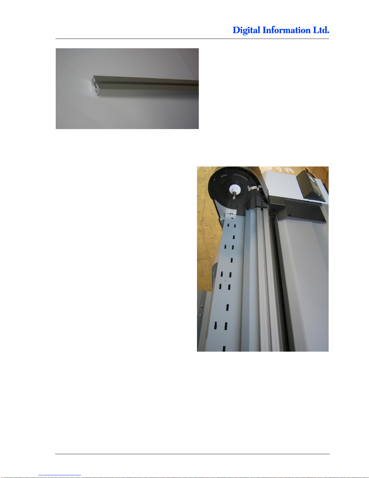
6.4.1 Additional Parts
Pos Amount
Name
Dimension in mm
51 1
Profile for Printer Bottom „for camera and paper feed holder“
40 x 80 x 1410
52 4 Screws M4 x 25
Page 44
6
Prepare the BACK Printer
Mount the Base Profile for Paper Guide / Camera holder
6-4 Preproofer x700 / x900 – HW Installation Manual
6.4.2 Mount the Profile
Take off the screws on the correct position on the
Epson printer. Mount the profile by using the M4
screws.
Page 45
Prepare the BACK Printer
Set the Wires
6
Preproofer x700 / x900 – HW Installation Manual 6-5
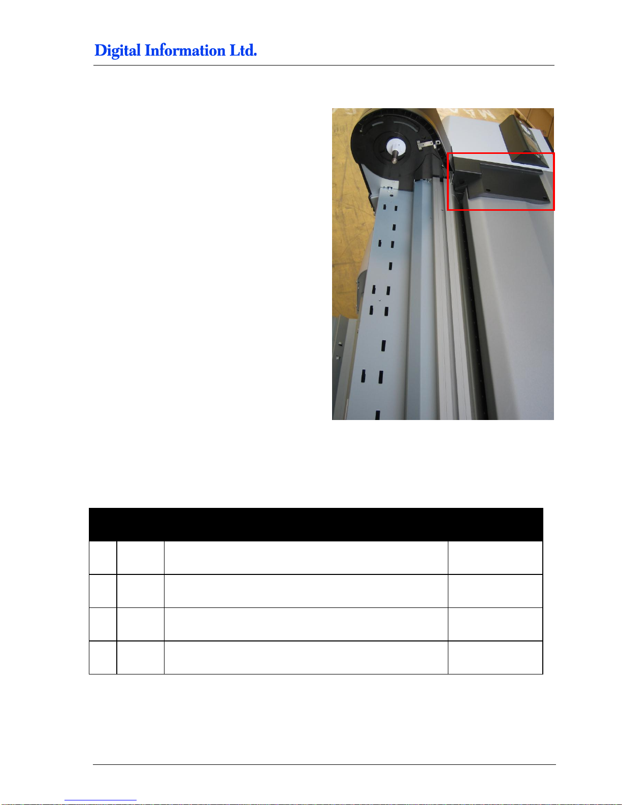
6.4.3 Optional: Take off the Black Side Cover
The Epson technician might need access to the
print head system when doing maintenance on the
Epson printer.
For the accessing the print head, the right cover
needs be taken off. The cover is locked with several
screws on the printer side and the black side cover
shown in the image to the left.
Taking the black side cover off, reduces the
disassembling of the Preproofer paper feed system
during an Epson service.
6.5 Set the Wires
6.5.1 Additional Parts
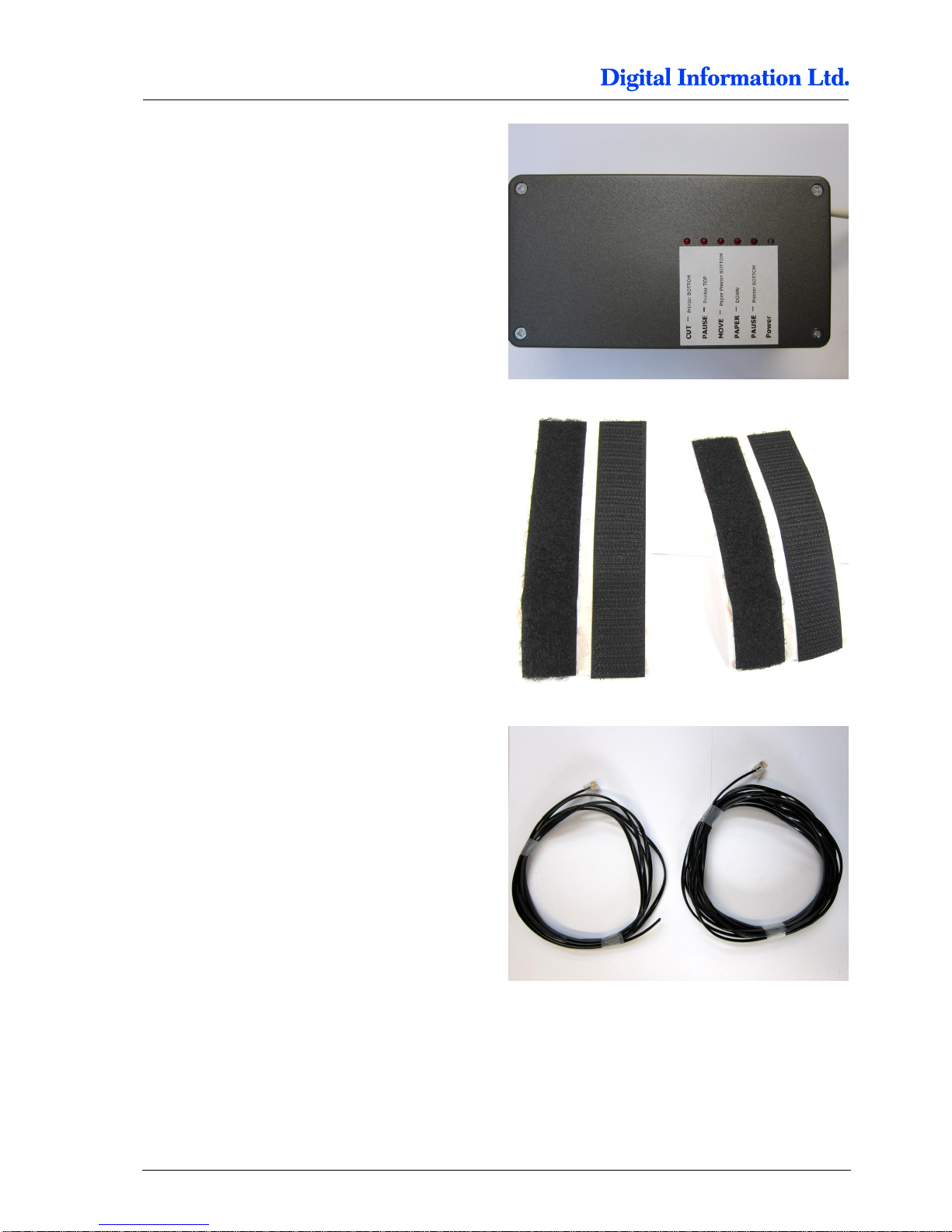
Pos Amount
Name
Dimension in mm
101 1
Electronic Box
102 1 Cable to connect the FRONT printer panel, approx. 2 meter
103 1 Cable to connect the BACK printer panel, approx. 4 meter
104 2 Velcro for fixing the electronic box to the printer, 8cm
Page 46
6
Prepare the BACK Printer
Set the Wires
6-6 Preproofer x700 / x900 – HW Installation Manual
Page 47
Prepare the BACK Printer
Set the Wires
6
Preproofer x700 / x900 – HW Installation Manual 6-7
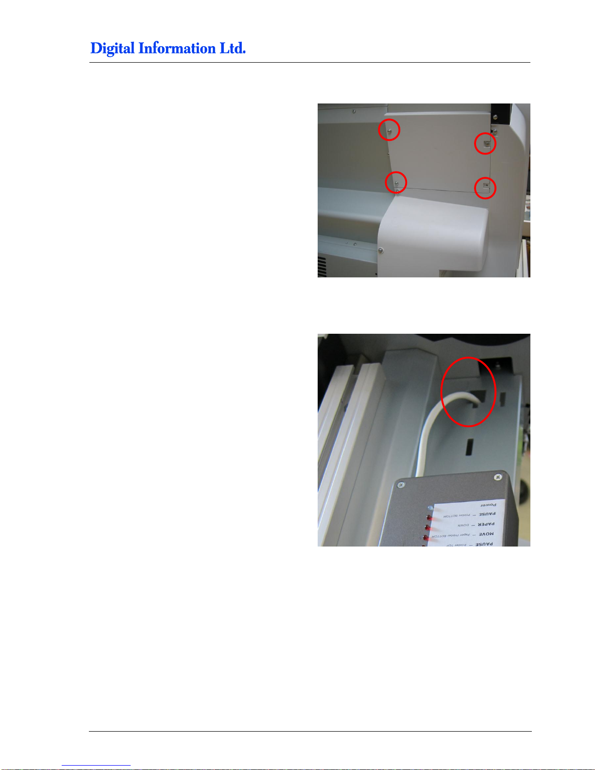
6.5.2 Open PCB Cover on the Epson Printer
Locate the cover and remove 4 screws.
6.5.3 Cable from Electronic Box
Put the white cable from the Electronic Box as
shown into the Printer.
Page 48
6
Prepare the BACK Printer
CUT MOTOR Setup
6-8 Preproofer x700 / x900 – HW Installation Manual
6.6 CUT MOTOR Setup
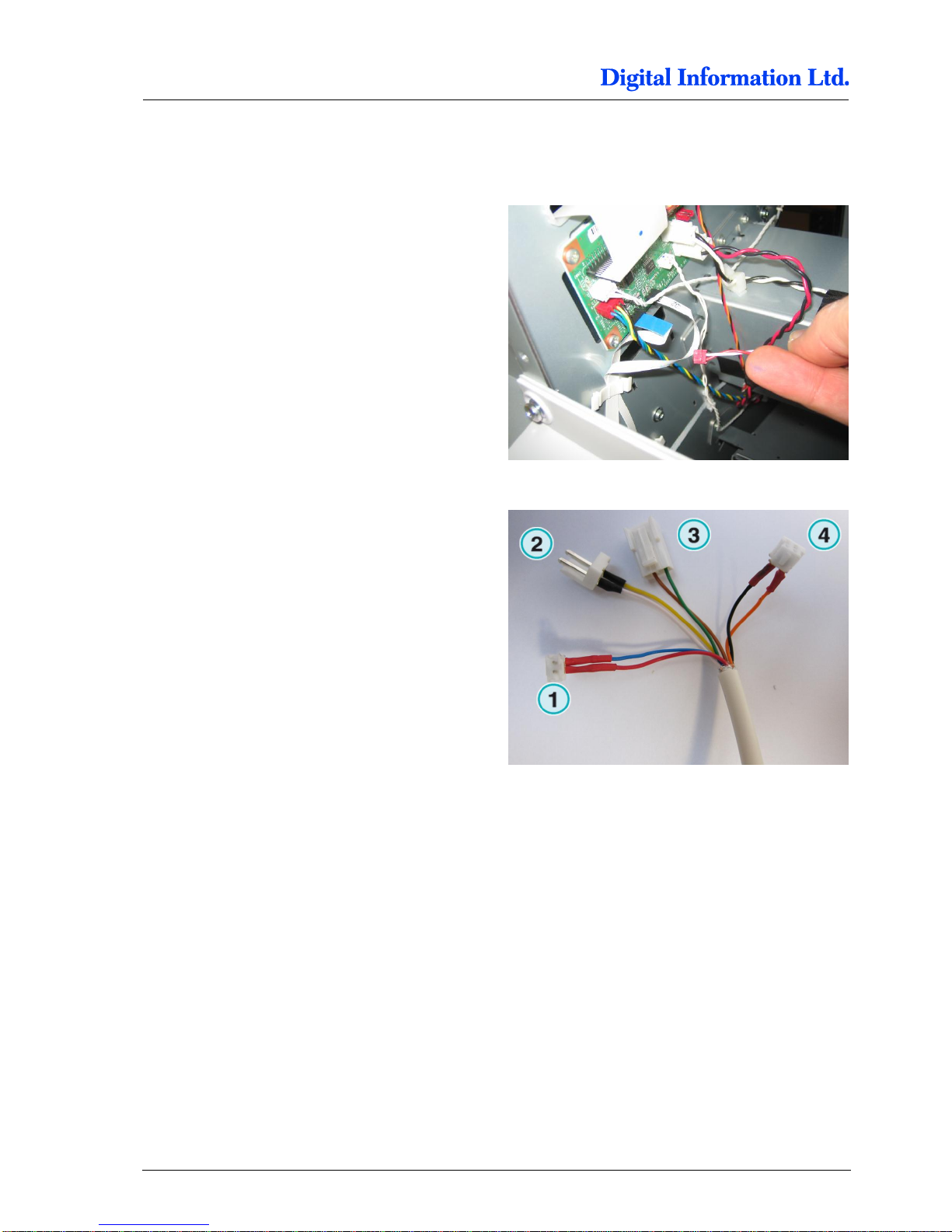
6.6.1 Remove the CUT Motor Cable
Take off the Cut Motor connector at the PCB board,
identified by WHITE / RED cable pair.
Plug the Cut Motor cable to the connector 1 from
the Electronic Box.
Plug the connector 4 from the Electronic Box into
the PCB board where previously the original Cut
Motor cable has been connected.
Page 49
Prepare the BACK Printer
PAPER FEED Motor Setup
6
Preproofer x700 / x900 – HW Installation Manual 6-9
6.7 PAPER FEED Motor Setup
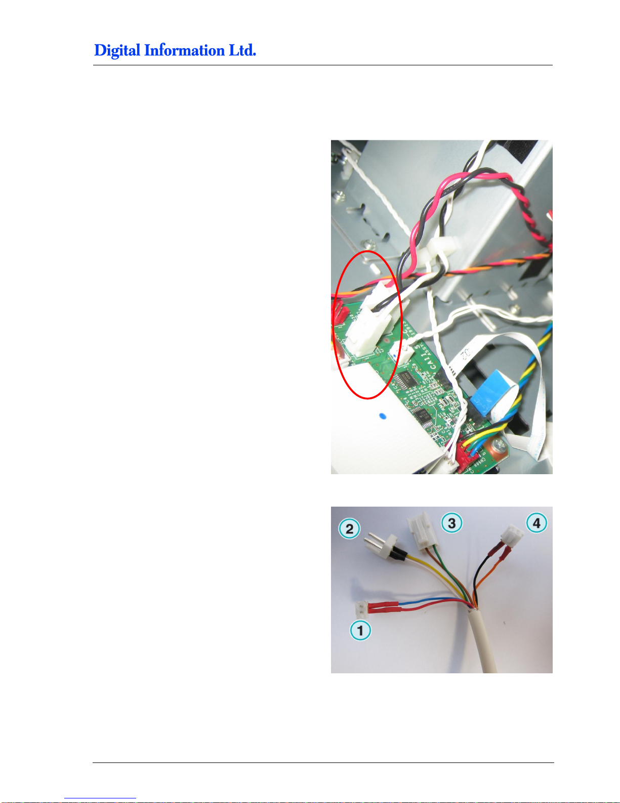
6.7.1 Take Off the Paper Feed Motor Cable
Take off the cable pair with the black and white
cables (thick cables).
Plug the Paper Feed Motor cable to the connector 2
from the Electronic Box.
Plug the connector 3 from the Electronic Box into
the PCB board where previously the original Paper
Feed Motor cable has been connected.
Page 50
6
Prepare the BACK Printer
PAPER FEED Motor Setup
6-10 Preproofer x700 / x900 – HW Installation Manual
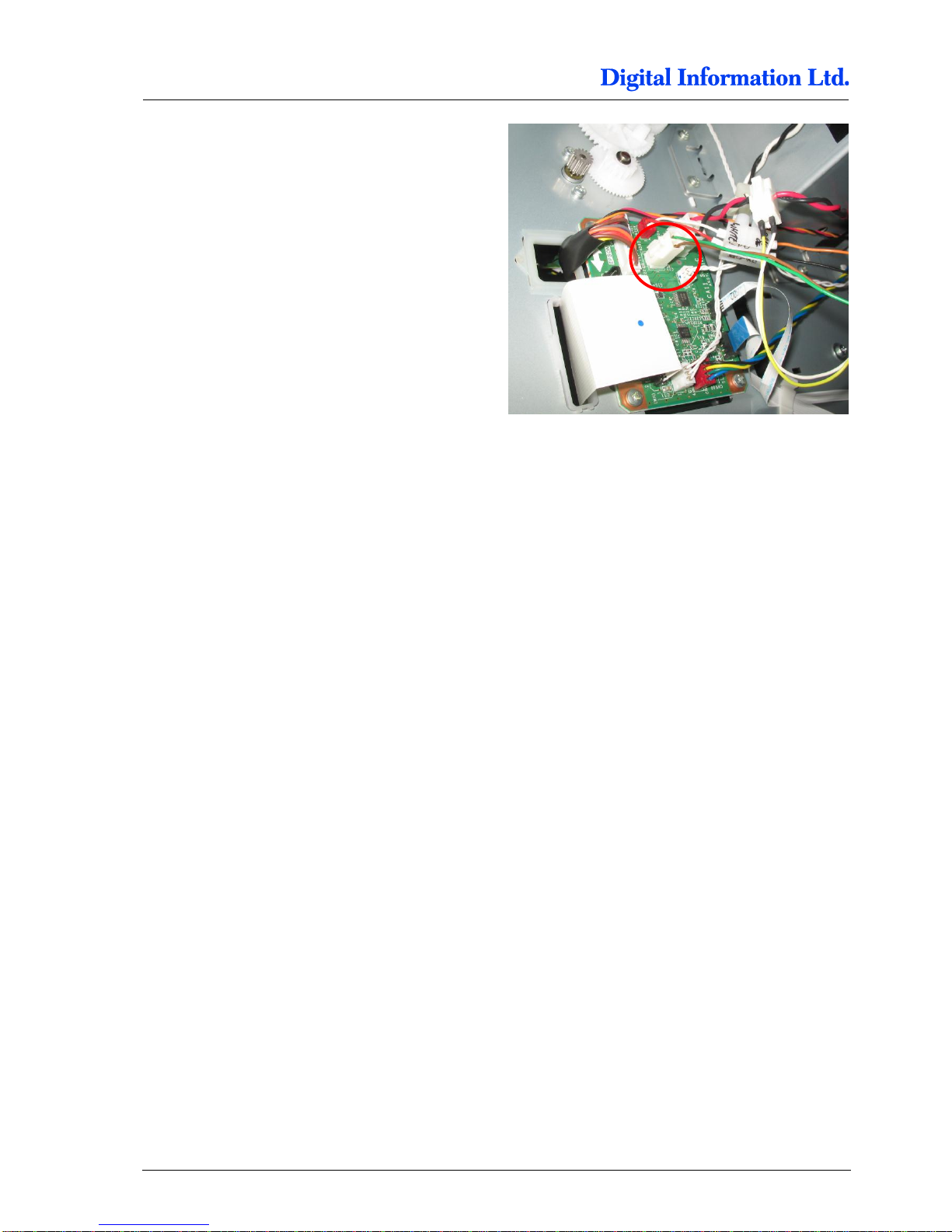
Cables at the PCB board after the connecting to the
Electronic Box.
Page 51
Prepare the BACK Printer
CUT MOTOR ENCODER Setup - Electronic Box - HW Release 2
6
Preproofer x700 / x900 – HW Installation Manual 6-11
6.8 CUT MOTOR ENCODER Setup - Electronic Box - HW Release 2
In November 2011, a new designed Electronic box
for the Preproofer has been released. The new
Electronic box is recognized by having three RJ11
connectors on the opposite side of the power
connector.
Beside internal hardware changes, the electronic
allows to control the cutter system on the Epson
printer through the cut motor encoder.
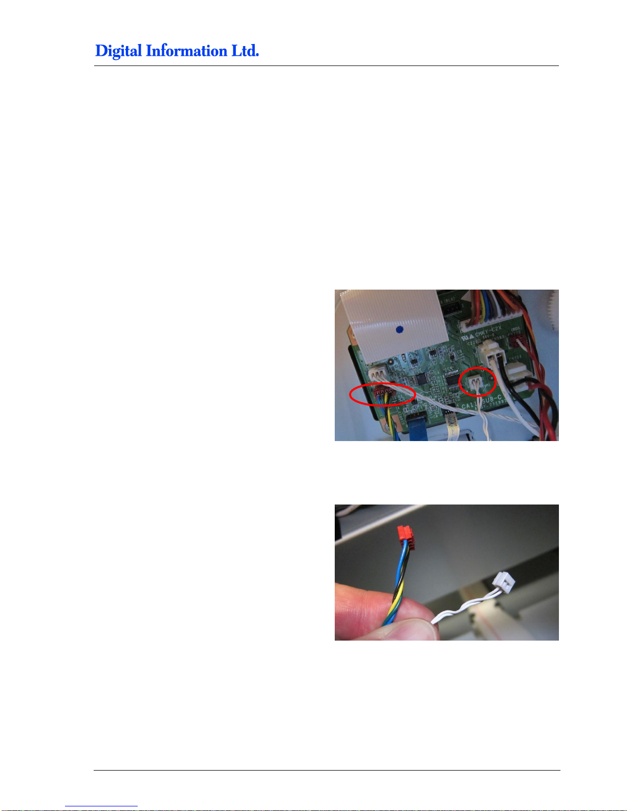
6.9 Take Off the End Switch and Encoder Cable
Locate on the PCB board the Cutter End Switch
cable pair (connector with the two white cables) and
the Cut Motor Encoder cable (connector with blue,
green, yellow and black cable).
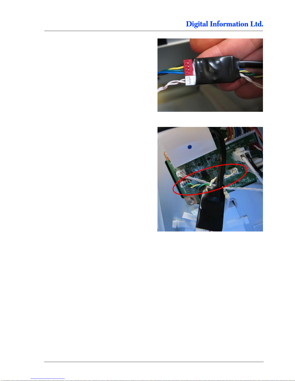
6.9.1 Take Off and Reconnect the End Switch and Encoder Cable
Plug out the two cables.
Page 52
6
Prepare the BACK Printer
Take Off the End Switch and Encoder Cable
6-12 Preproofer x700 / x900 – HW Installation Manual
Plug the two cables into the connector coming from
the ElectronicBox.
Plug the two cables which are coming from the
backside of this cable into the two free connectors.
Page 53
Prepare the BACK Printer
Wire the Control Panel Back Printer
6
Preproofer x700 / x900 – HW Installation Manual 6-13
6.10 Wire the Control Panel Back Printer
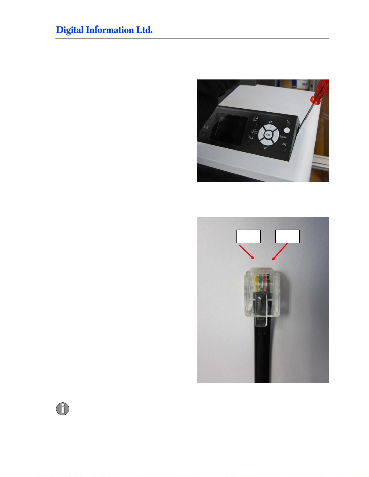
6.10.1 Remove the Control Panel
Remove the control panel like shown.
Unplug the panel from the flat ribbon cable.
Take off the metal cover.
6.10.2 Solder the Wires to the Panel
Cable layout is shown on the right.
Pin 1 and Pin6 are empty. The first cable on
the right is Pin2!
Pin 5
Pin 2
Page 54
6
Prepare the BACK Printer
Wire the Control Panel Back Printer
6-14 Preproofer x700 / x900 – HW Installation Manual
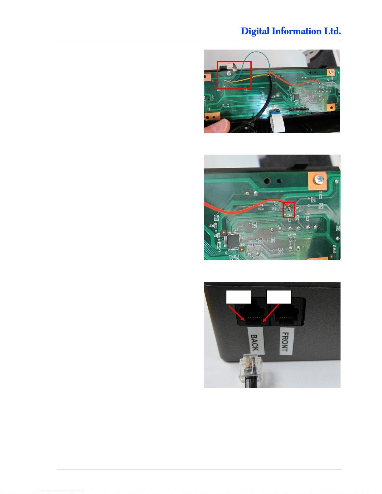
Locate the solder points for GROUND and PAUSE.
Thick conducting path is GROUND, thin path is
PAUSE.
On the picture to the right, the cables are:
YELLOW = PAUSE
GREEN = GROUND
Locate the solder point for “PAPER FEED DOWN”.
On the picture to the right, the cables are:
RED = PAPER FEED DOWN
Check with the delivered cable (RJ11 connector at
one end) the correct cable assignment and solder
the wires to the panel.
For the BACK Printer, the pins are located like
Pin 3 = PAPER FEED DOWN
Pin 4 = GROUND
Pin 5 = PAUSE
For the FRONT Printer assignment, see chapter
7.1.2
Pin 6
Pin 1
Page 55
Prepare the BACK Printer
Wire the Control Panel Back Printer
6
Preproofer x700 / x900 – HW Installation Manual 6-15
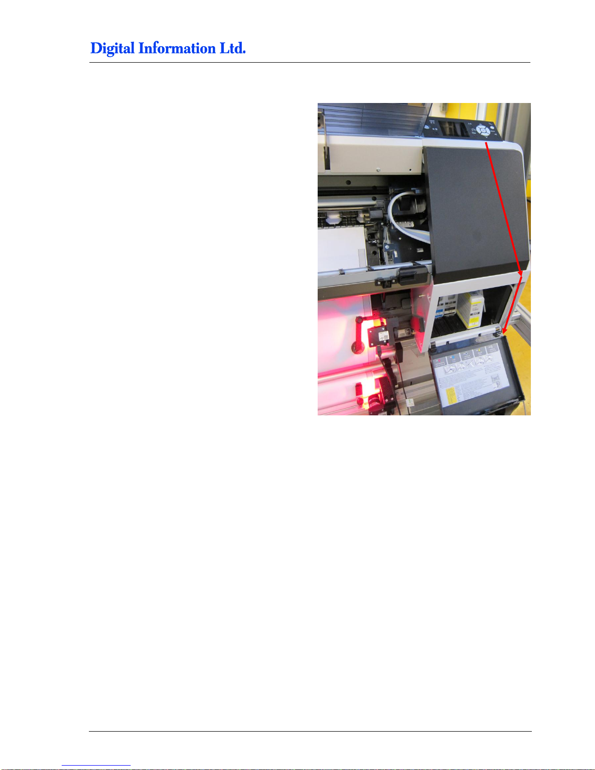
6.10.3 Guide the Cable to the Electronic Box
Put the cable straight down through the hole where
the flat ribbon cable goes through. Guide it to the
side of the ink compartment and bring it out below
the ink compartment.
Page 56

6
Prepare the BACK Printer
Wire the Control Panel Back Printer
6-16 Preproofer x700 / x900 – HW Installation Manual
Page 57
Prepare the FRONT Printer
Wire the Control Panel Front Printer
7
Preproofer x700 / x900 – HW Installation Manual 7-1
7 Prepare the FRONT Printer
7.1 Wire the Control Panel Front Printer
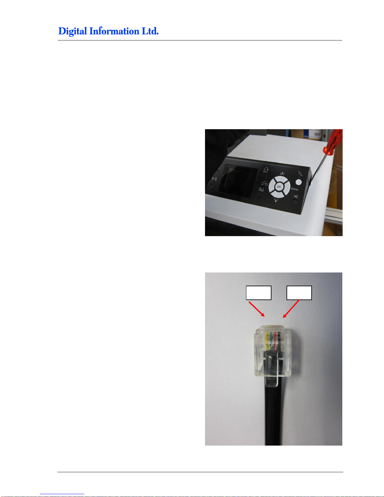
7.1.1 Take off the Control Panel
Remove the control panel like shown.
Unplug the panel from the flat ribbon cable.
Take off the metal cover.
7.1.2 Solder the Wires to the Panel
Cable layout is shown on the right.
Pin 5
Pin 2
Page 58
7
Prepare the FRONT Printer
Wire the Control Panel Front Printer
7-2 Preproofer x700 / x900 – HW Installation Manual
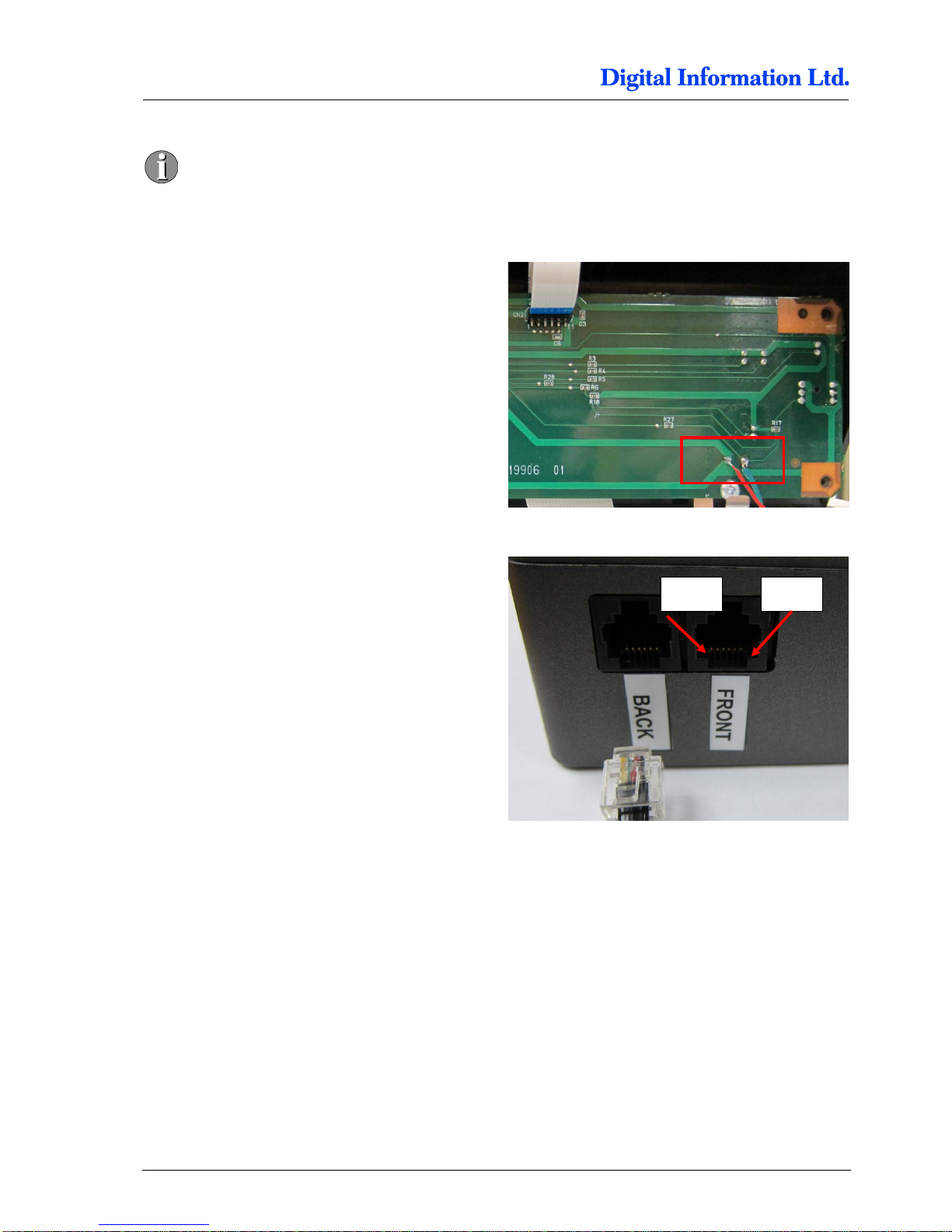
Pin 1 and Pin 6 are empty. The first cable
on the right is Pin 2!
Locate the solder points for GROUND and PAUSE.
On the picture to the right, the cables are:
GREEN = PAUSE
RED = GROUND
Check with the delivered cable (RJ11 connector at
one end) the correct cable assignment and solder
the wires to the panel.
For the FRONT Printer, the pins are located like
Pin 3 = GROUND
Pin 4 = PAUSE
Pin 6
Pin 1
Page 59
Prepare the FRONT Printer
Wire the Control Panel Front Printer
7
Preproofer x700 / x900 – HW Installation Manual 7-3
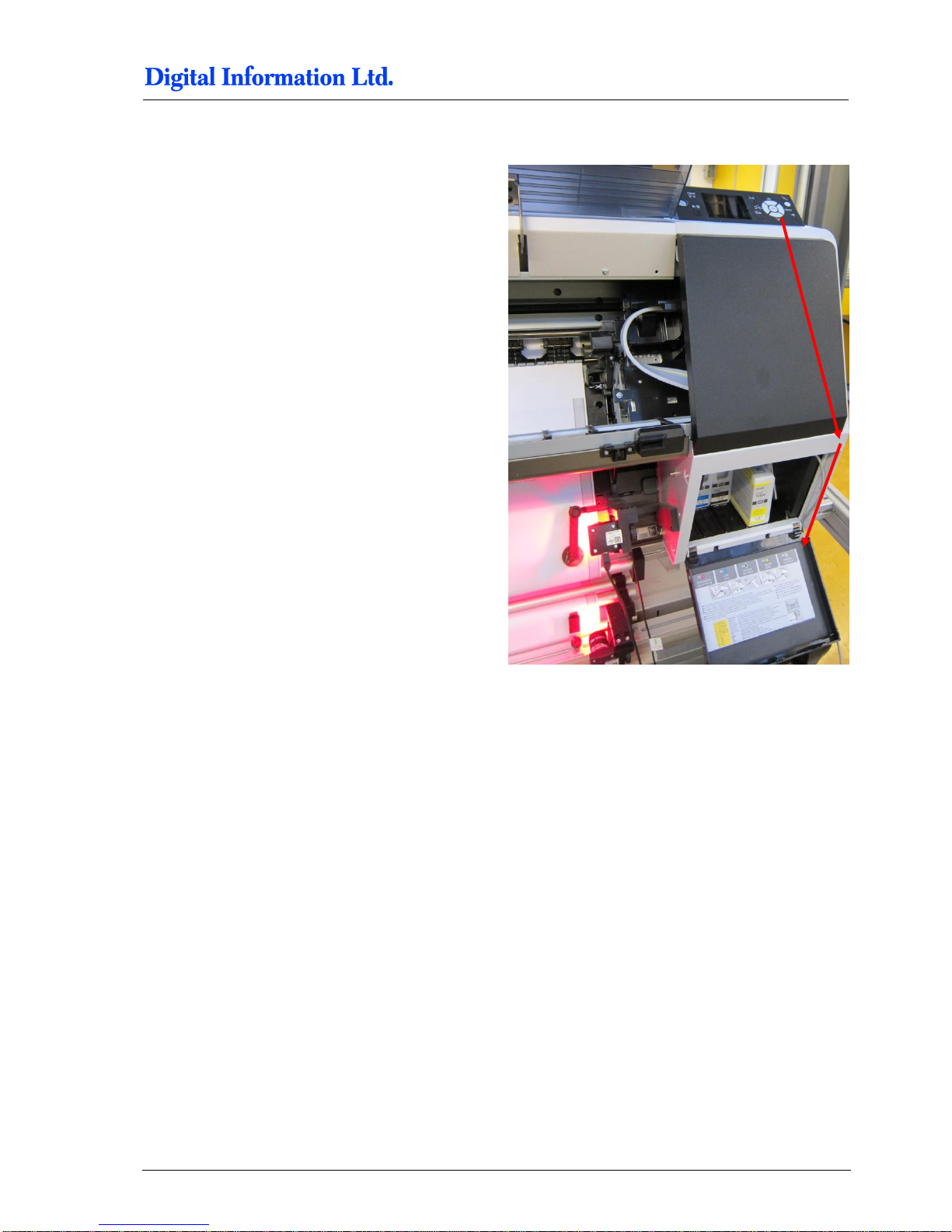
7.1.3 Guide the Cable to the Electronic Box
Put the cable straight down through the hole where
the flat ribbon cable goes through. Guide it to the
side of the ink compartment and bring it out below
the ink compartment.
Page 60

7
Prepare the FRONT Printer
Wire the Control Panel Front Printer
7-4 Preproofer x700 / x900 – HW Installation Manual
Page 61
Set the Printers into the Stand
Wire the Control Panel Front Printer
8
Preproofer x700 / x900 – HW Installation Manual 8-1
8 Set the Printers into the Stand
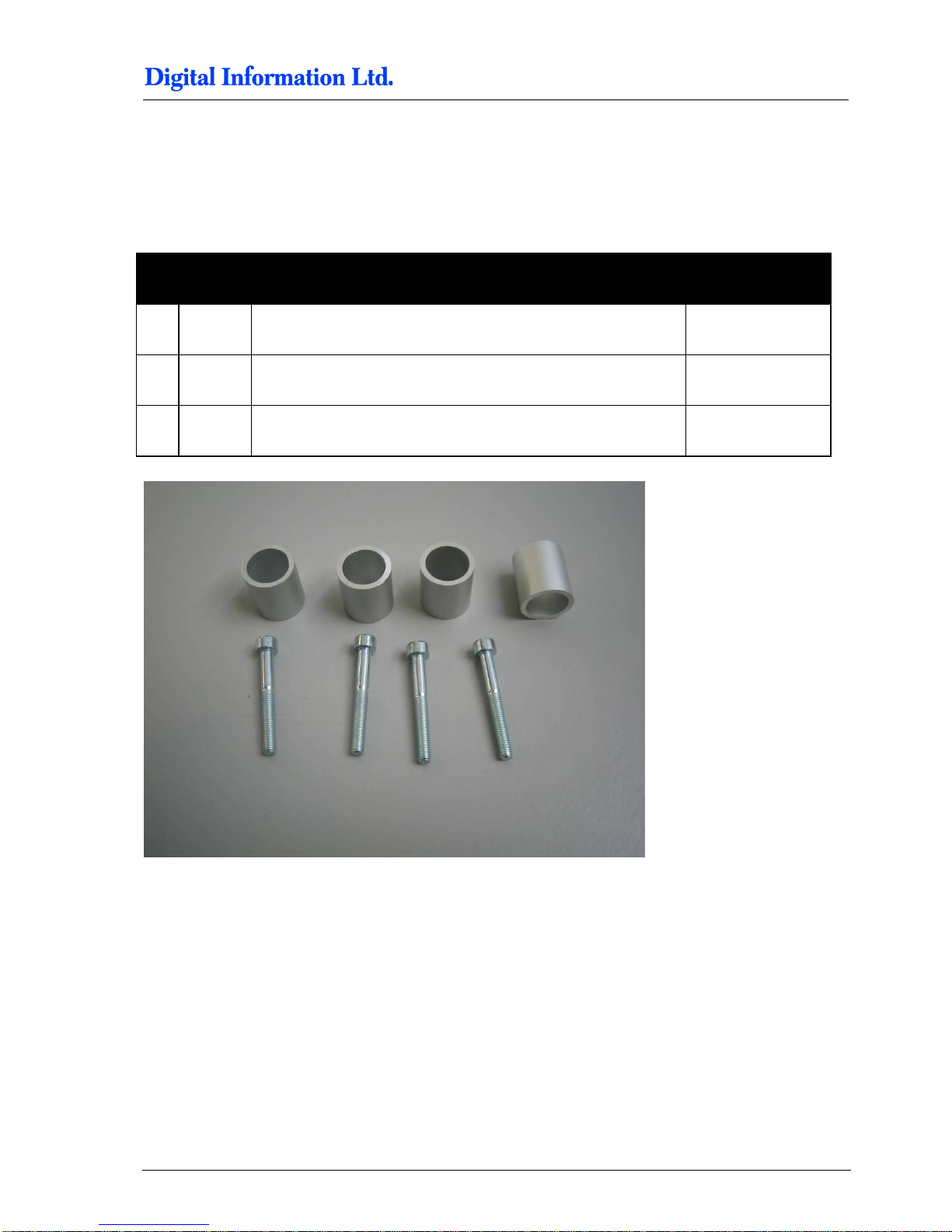
8.1.1 Additional Parts
Pos Amount
Name
Dimension in mm
54 4
Aluminum Cylinder
20mm diameter x
23mm length
55 4 Screws M6 x 40
4 Washer M8 wide
Page 62
8
Set the Printers into the Stand
Back Printer
8-2 Preproofer x700 / x900 – HW Installation Manual
8.2 Back Printer
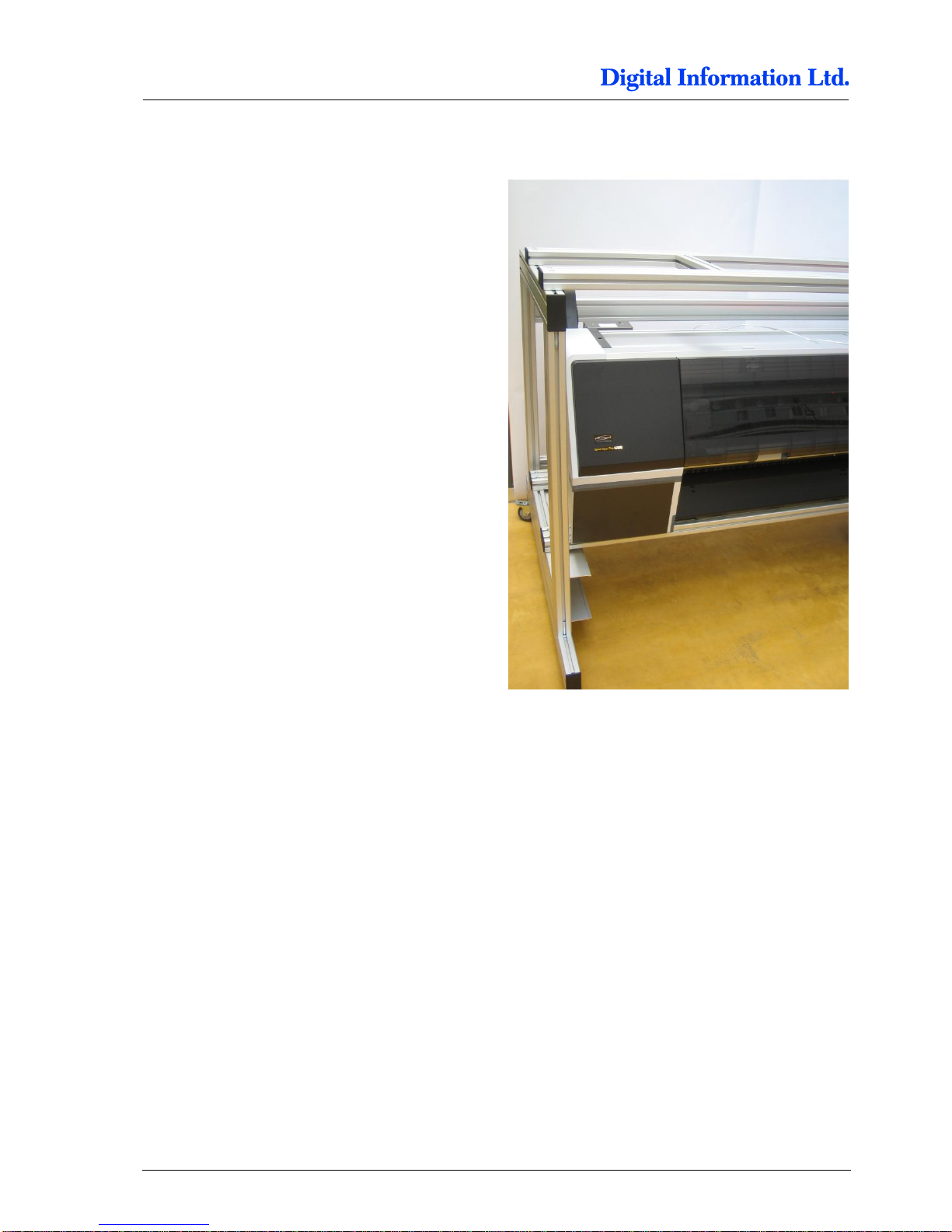
Set the back printer on the stand.
Note
Tighten the printer immediately to the stand with the
delivered screws.
Page 63
Set the Printers into the Stand
Back Printer
8
Preproofer x700 / x900 – HW Installation Manual 8-3
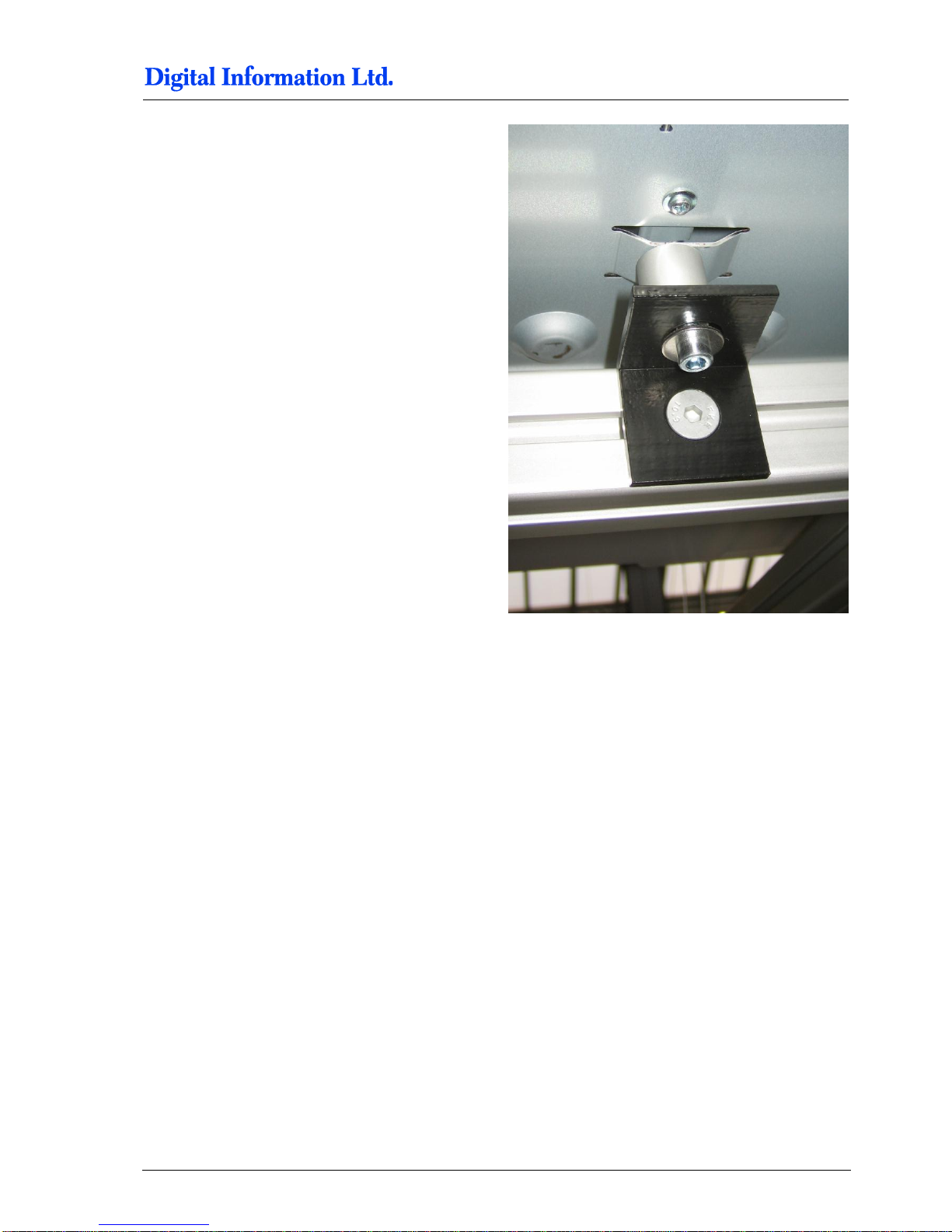
Mount the printer to the stand.
Page 64
8
Set the Printers into the Stand
Front Printer
8-4 Preproofer x700 / x900 – HW Installation Manual
8.3 Front Printer
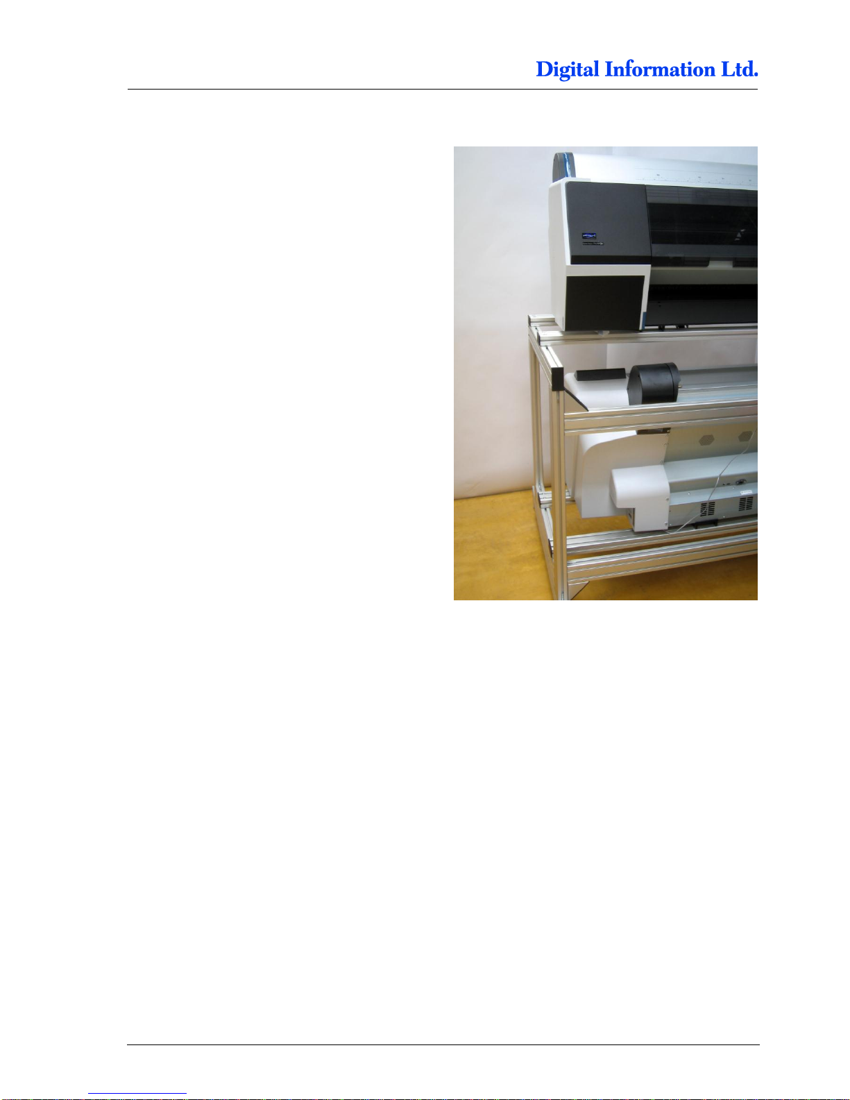
Set the back printer to the stand and tight it
immediately to the stand with the screws.
Page 65
Paper Guide / Camera System
Side parts - Step 1
9
Preproofer x700 / x900 – HW Installation Manual 9-1
9 Paper Guide / Camera System
9.1 Side parts - Step 1
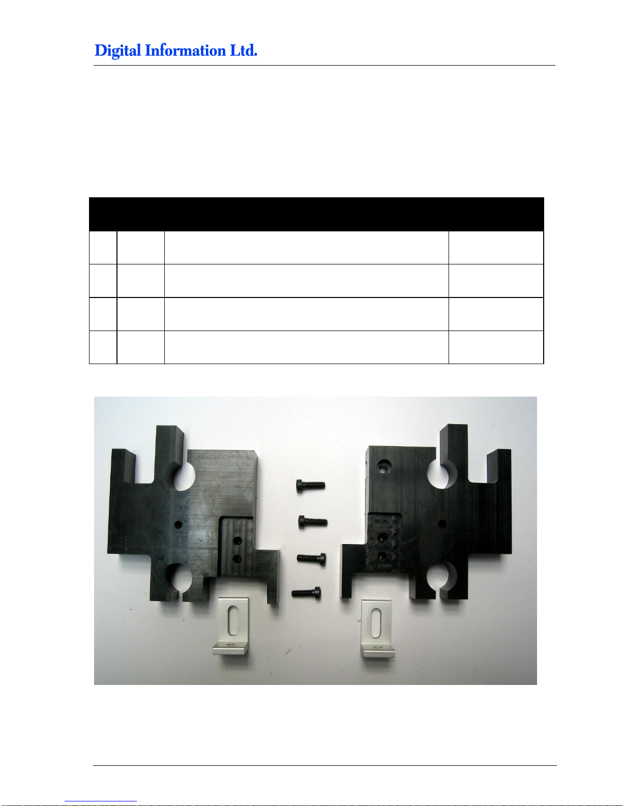
9.1.1 Parts used
Pos Amount
Name
Dimension in mm
03 1
Left sided holder
04 1 Right sided holder
56 2 Bracket
25 x 35
57 5 Screw M5 x 16
Page 66
9
Paper Guide / Camera System
Side parts - Step 1
9-2 Preproofer x700 / x900 – HW Installation Manual
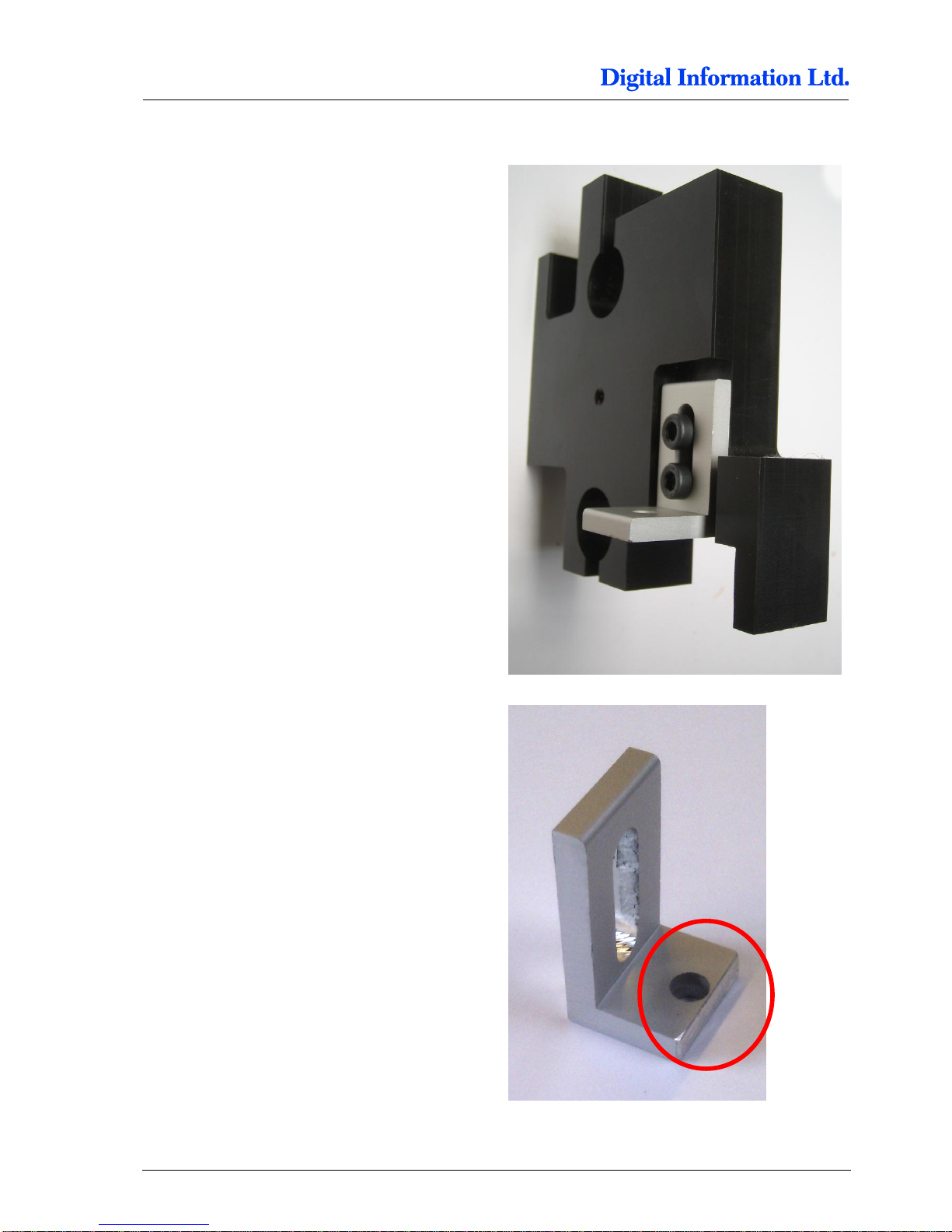
9.1.2 Assembly
Mount the bracket for the left holder as shown.
Use on this holder, the bracket which is shorter on
this side.
Page 67
Paper Guide / Camera System
Side Parts - Camera Holder BACK Printer
9
Preproofer x700 / x900 – HW Installation Manual 9-3
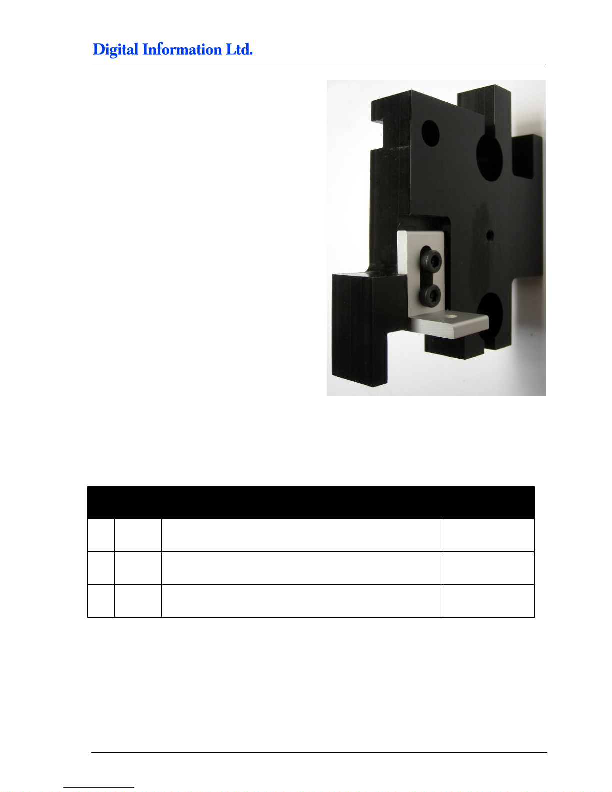
Mount the bracket as shown for the right holder.
9.2 Side Parts - Camera Holder BACK Printer
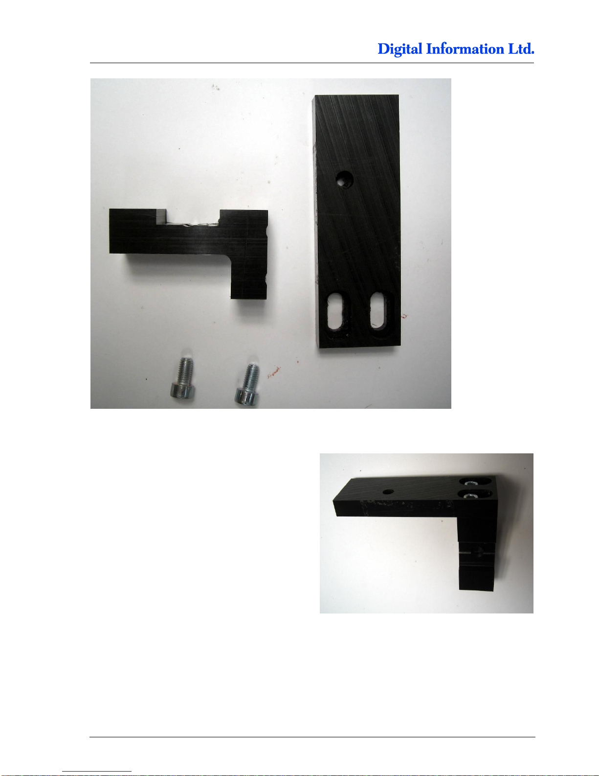
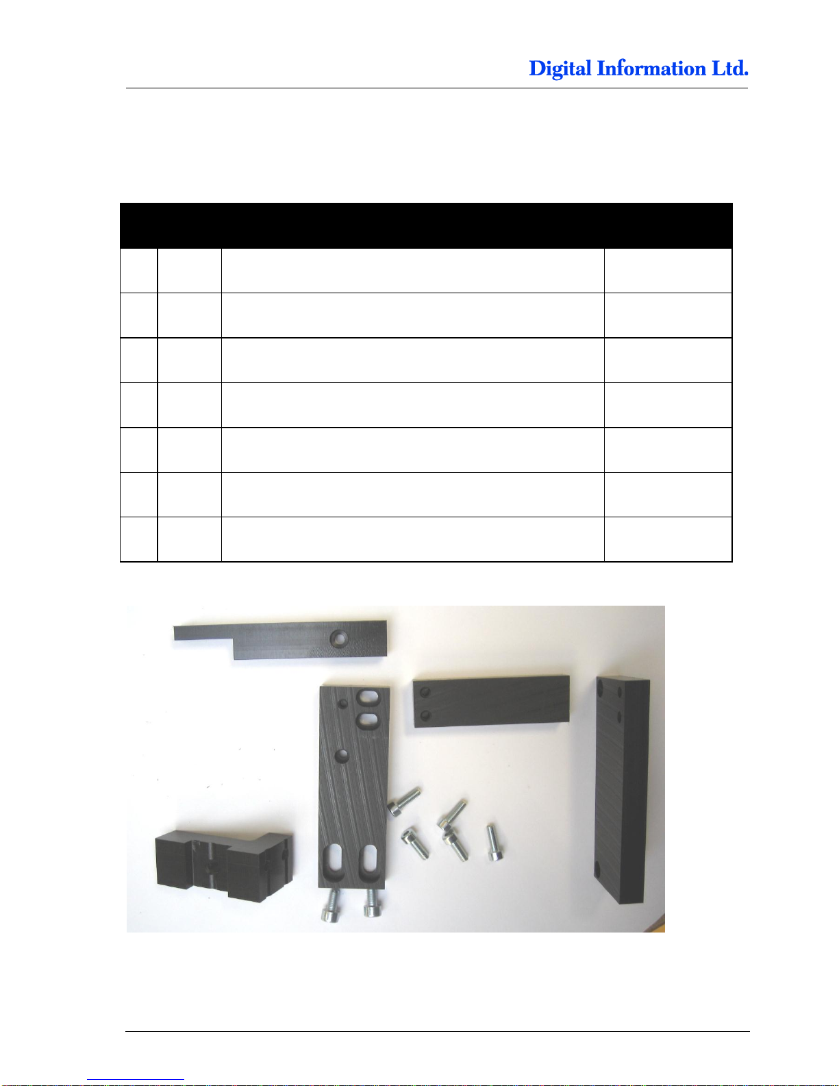
9.2.1 Parts used
Pos Amount
Name
Dimension in mm
06 1
Camera holder BACK printer
07 1 Camera holder
58 2 Screw M5 x 10
Page 68
9
Paper Guide / Camera System
Side Parts - Camera Holder BACK Printer
9-4 Preproofer x700 / x900 – HW Installation Manual
9.2.2 Assembly
Mount the camera parts as shown.
Page 69
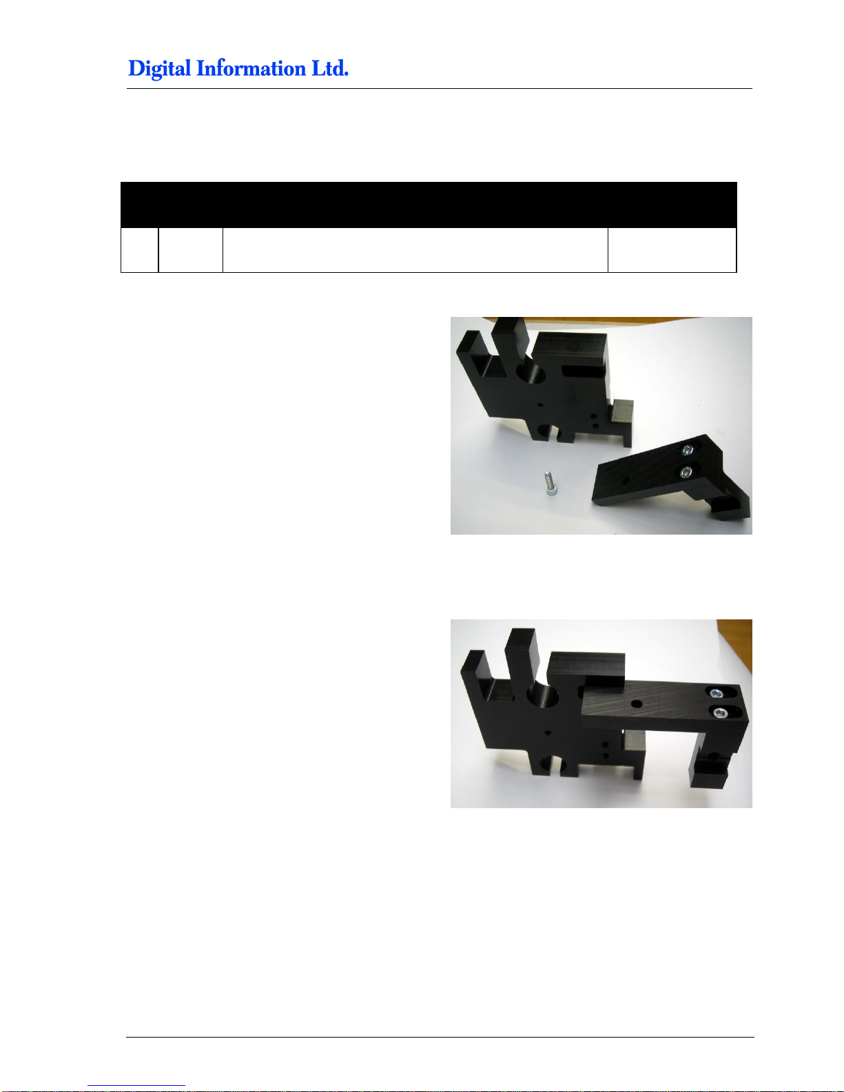
Paper Guide / Camera System
Assembly „Right Holder“ and „Camera holder“
9
Preproofer x700 / x900 – HW Installation Manual 9-5
9.3 Assembly „Right Holder“ and „Camera holder“
9.3.1 Parts used
Pos Amount
Name
Dimension in mm
59 1 Screw M5 x 20
9.3.2 Assembly
Assembly now the two parts like shown.
Page 70
9
Paper Guide / Camera System
Assembly Camera Holder Front Printer
9-6 Preproofer x700 / x900 – HW Installation Manual
9.4 Assembly Camera Holder Front Printer
9.4.1 Parts used
Pos Amount
Name
Dimension in mm
07 1 Camera holder
08 1
Camera holder for Front printer
09 1 Camera holder Front Printer, mount to Epson Printer
10 1 Distance holder, set between Pos 8 and 9
11 1 Paper positioning support
60 2
Screws M5 x 10
61 5
Screws M4 x 12
Page 71
Paper Guide / Camera System
Mount Side Holder Parts to BACK printer
9
Preproofer x700 / x900 – HW Installation Manual 9-7
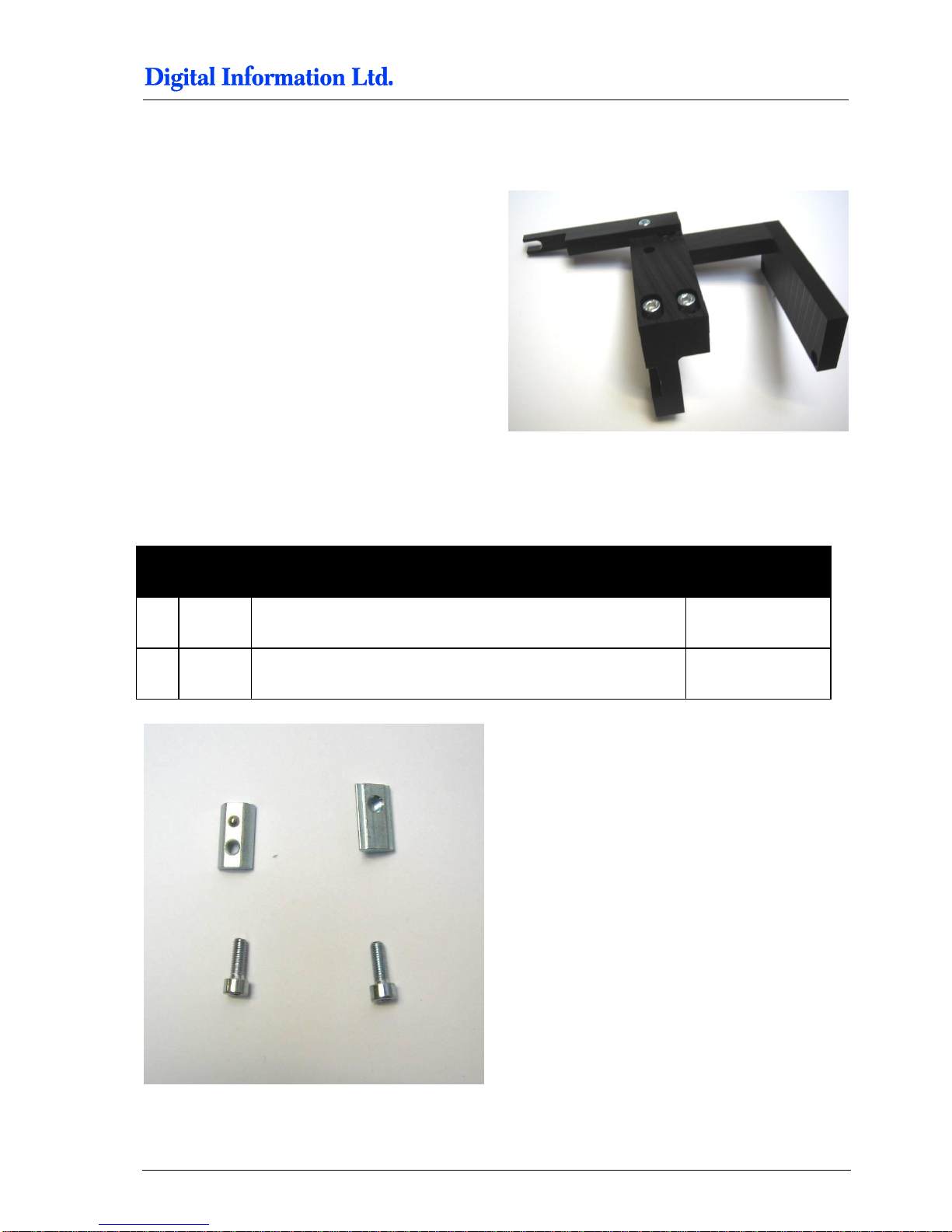
9.4.2 Assembly
Assembly now the two parts like shown
9.5 Mount Side Holder Parts to BACK printer
9.5.1 Additional parts
Pos Amount
Name
Dimension in mm
62 2
Screws M5 x 14
63 2 Slot Nut (thin) M5
Page 72
9
Paper Guide / Camera System
Mount Side Holder Parts to BACK printer
9-8 Preproofer x700 / x900 – HW Installation Manual
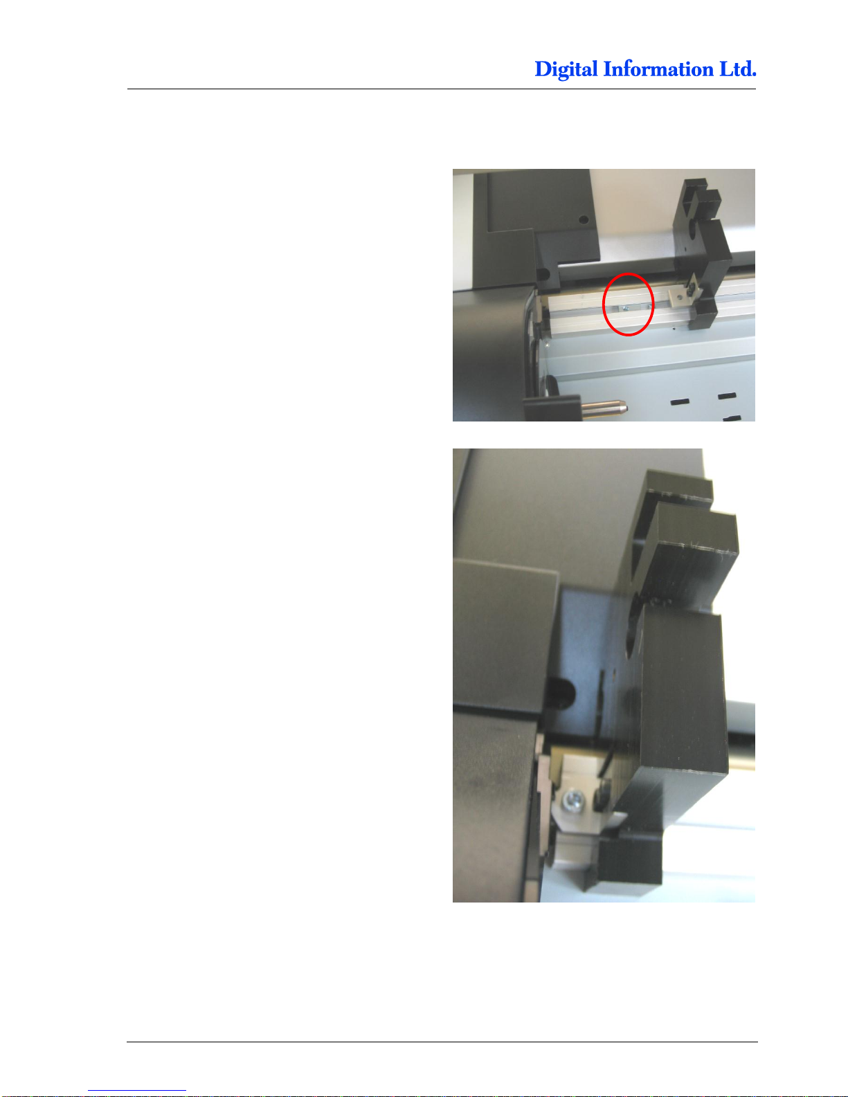
9.5.2 Mount the side holders to Profile
Put the thin M5 slot nut into the profile like shown.
Use the M5 screw to fix the side holder to the
profile. Push the side holder as much as possible to
left side position.
Do the same on the opposite side.
Page 73
Paper Guide / Camera System
Paper Guide Tubes
9
Preproofer x700 / x900 – HW Installation Manual 9-9
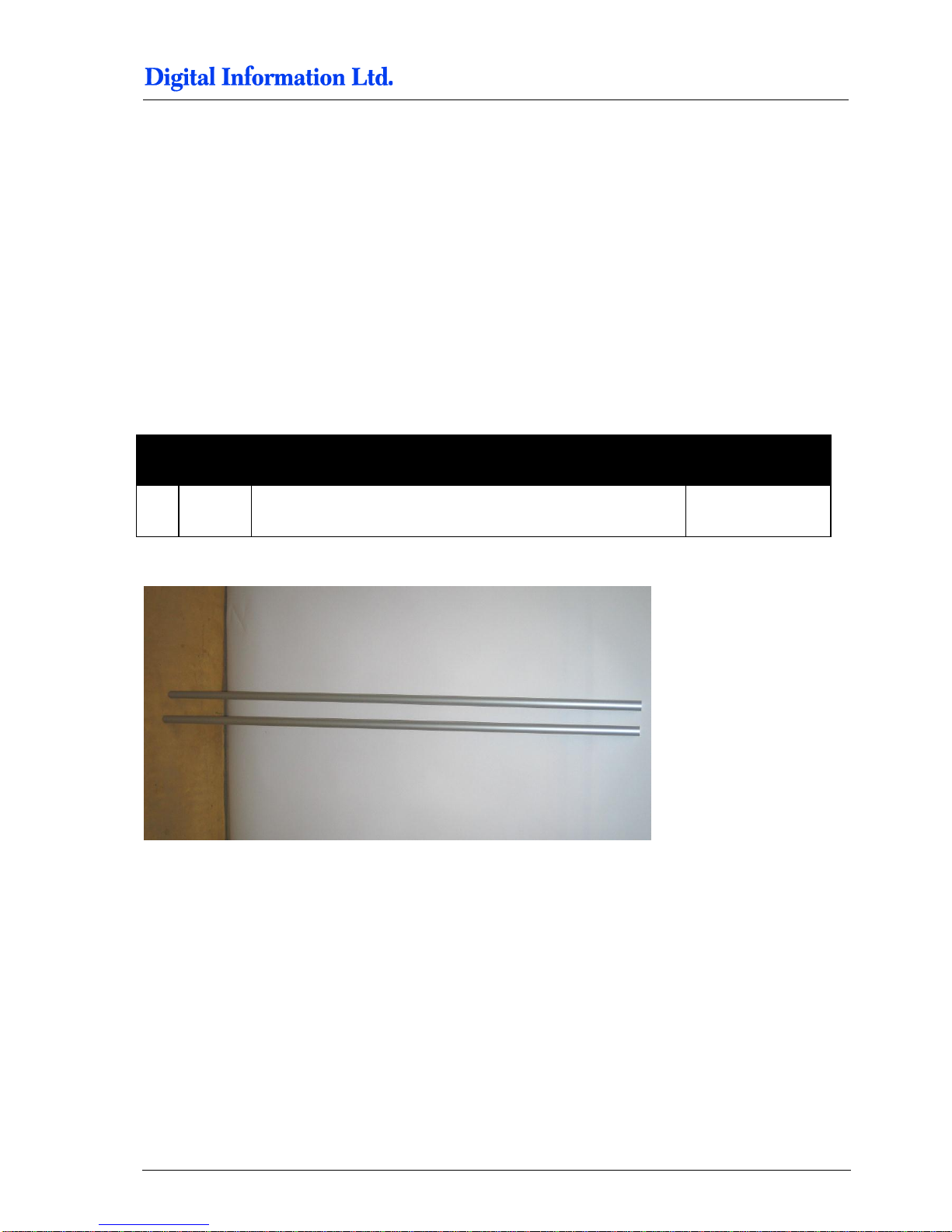
Put a thin slot nut into the profile. Use the M5 screw
to fix the side holder to the profile.
The distance between the side holders are 1166mm,
measured from the outer side to the outer side of
the frame holders.
9.6 Paper Guide Tubes
9.6.1 Additional parts
Pos Amount
Name
Dimension in mm
64 2
Aluminum tubes, 20mm diameter
1165
Page 74
9
Paper Guide / Camera System
Paper Guide Tubes
9-10 Preproofer x700 / x900 – HW Installation Manual
9.6.2 Mount Paper Guide Tubes
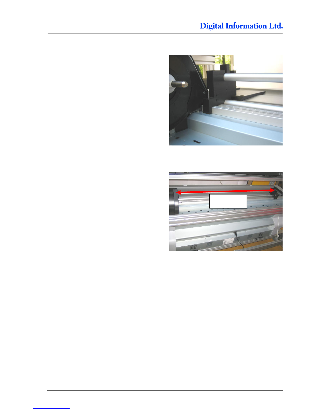
Mount the two tubes into the side holder left.
Shift the right sided side holder into the tubes.
The distance between the two side holders is
1166mm, measured from the outer side of the side
holders.
1166mm
Page 75
Paper Guide / Camera System
Tube Stopper
9
Preproofer x700 / x900 – HW Installation Manual 9-11
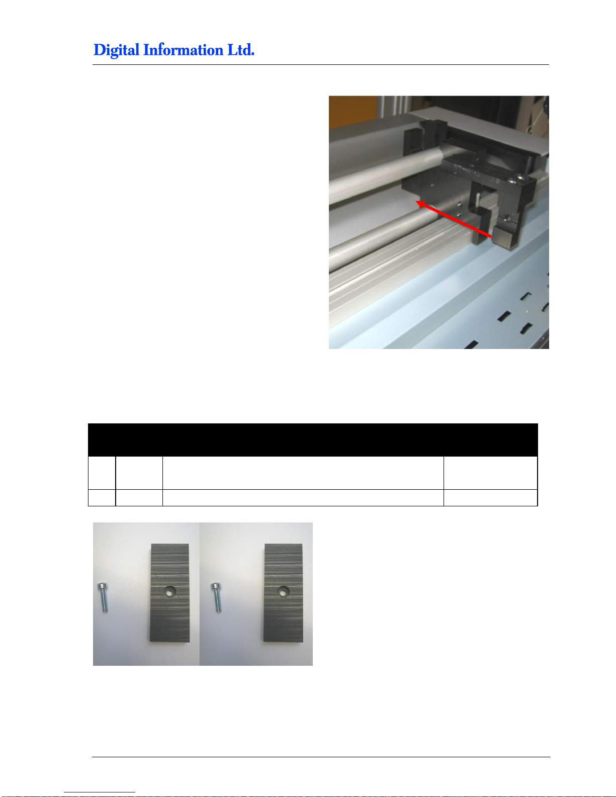
Push the side holder in this direction and tighten the
screw.
Note:
The upper tube should rotate as smoothly as
possible.
9.7 Tube Stopper
9.7.1 Additional parts
Pos Amount
Name
Dimension in mm
65 2
Screw M4 x 16
05 2 Side parts
Page 76
9
Paper Guide / Camera System
Add Slot Nuts to Profile Front Printer
9-12 Preproofer x700 / x900 – HW Installation Manual
9.7.2 Mount tube stopper
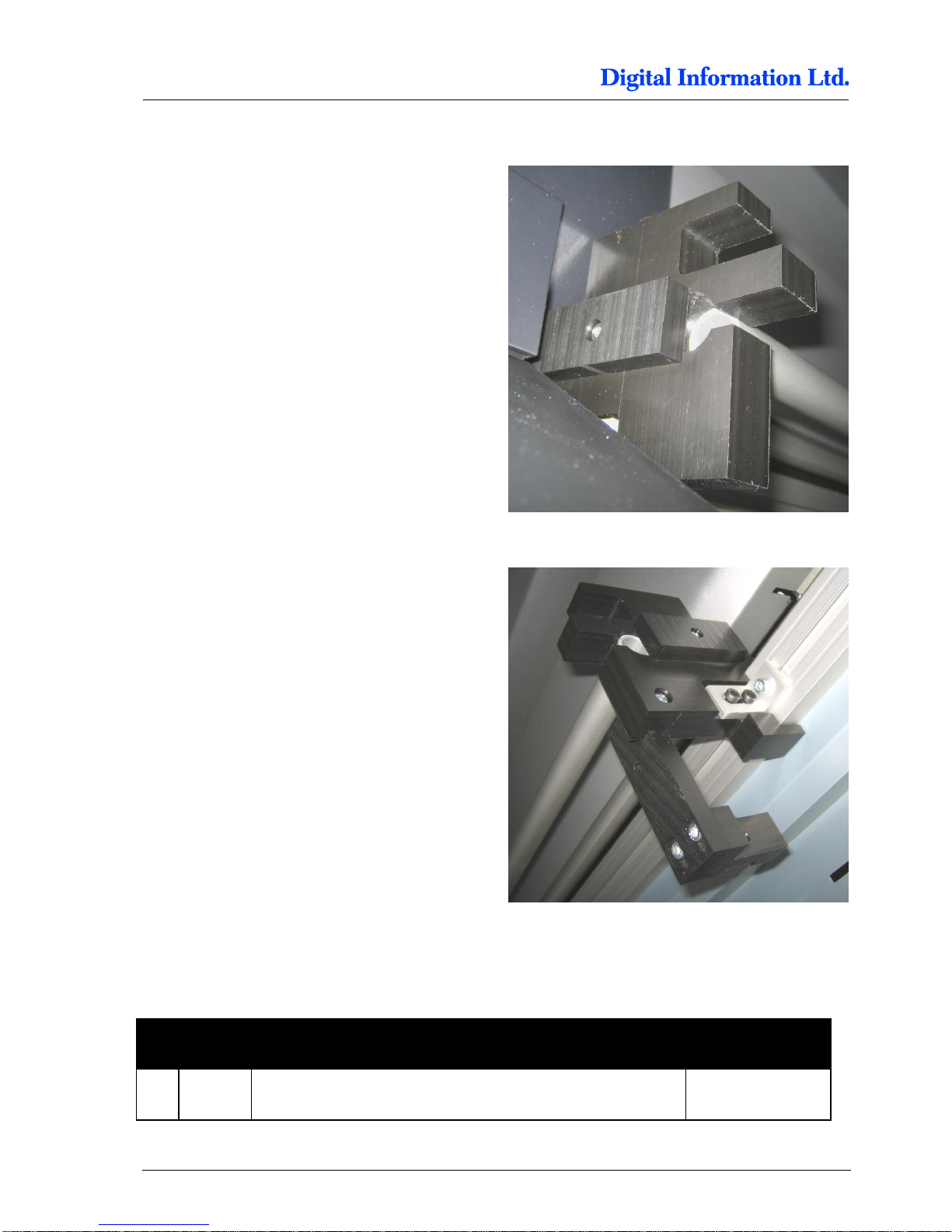
Mount it on the left side holder.
Mount it on the right side holder.
9.8 Add Slot Nuts to Profile Front Printer
9.8.1 Additional Parts
Pos Amount
Name
Dimension in mm
66 6
Slot nut M5
Page 77
Paper Guide / Camera System
Add Slot Nuts to Profile Front Printer
9
Preproofer x700 / x900 – HW Installation Manual 9-13
9.8.2 Slot nuts for Paper Guide Profile
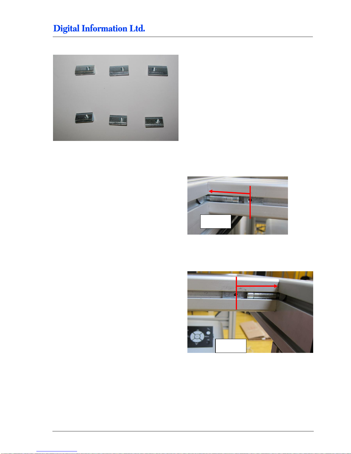
Mount four M5 slot nuts into the profile where the
Front printer stands on, each 45 mm from the side
frame.
45 mm
45 mm
Page 78
9
Paper Guide / Camera System
Add Paper Guide and Paper Tension Parts
9-14 Preproofer x700 / x900 – HW Installation Manual
9.9 Add Paper Guide and Paper Tension Parts
9.9.1 Additional Parts
Pos Amount
Name
Dimension in mm
67 2
Screw M5 x 40
68 2 Screw M5 x 12
69 2 Screw M5 x 20
70 2 Aluminum Tube 20mm
20mm diameter x
30mm length
71 2 Tension Tube Guide
20mm width,
600mm length
01 1 Tube holder, right side
02 1 Tube holder, left side
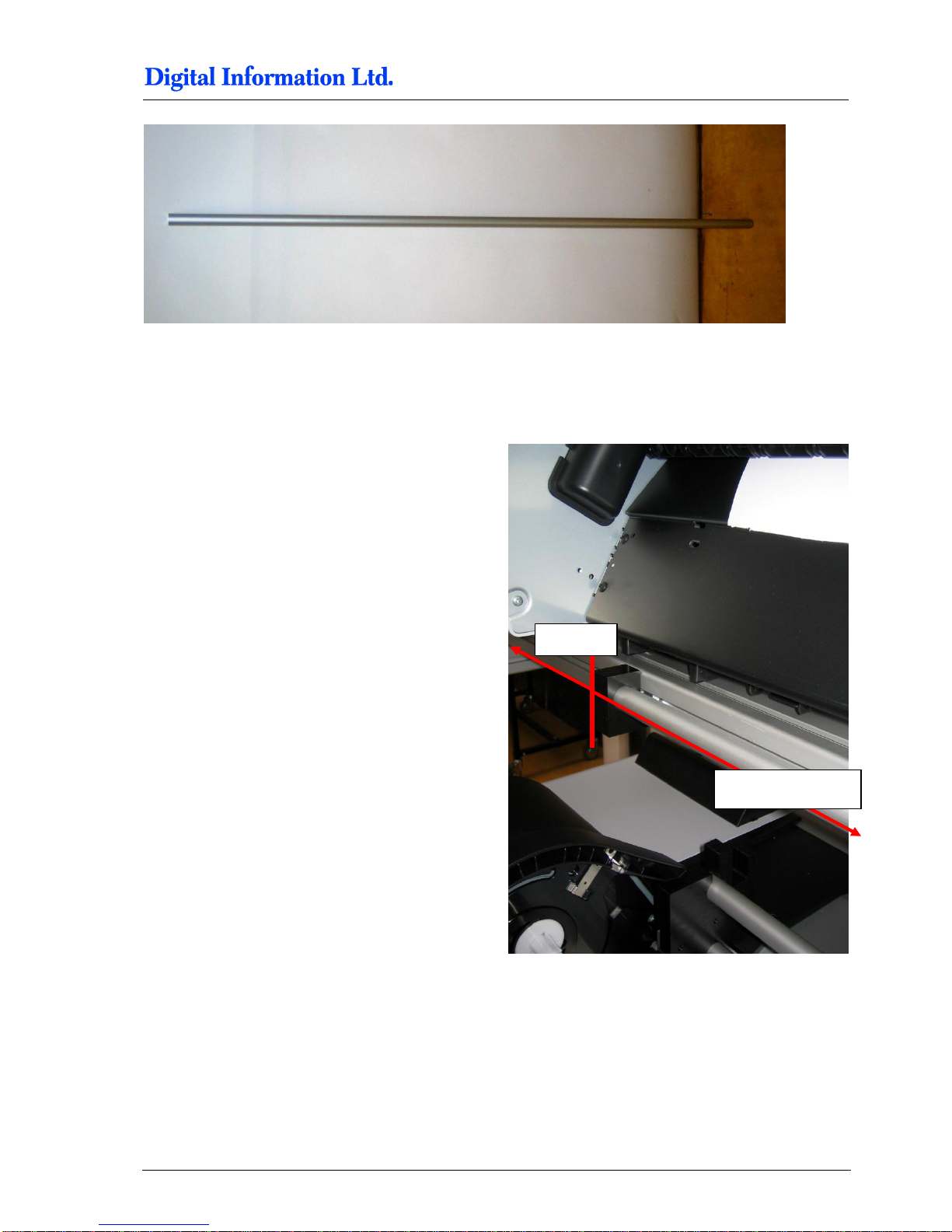
72 1 Aluminum Tube 20mm
20mm diameter x
1950 mm length
Page 79
Paper Guide / Camera System
Add Paper Guide and Paper Tension Parts
9
Preproofer x700 / x900 – HW Installation Manual 9-15
9.9.2 Mount Paper Guide Tube Front Printer
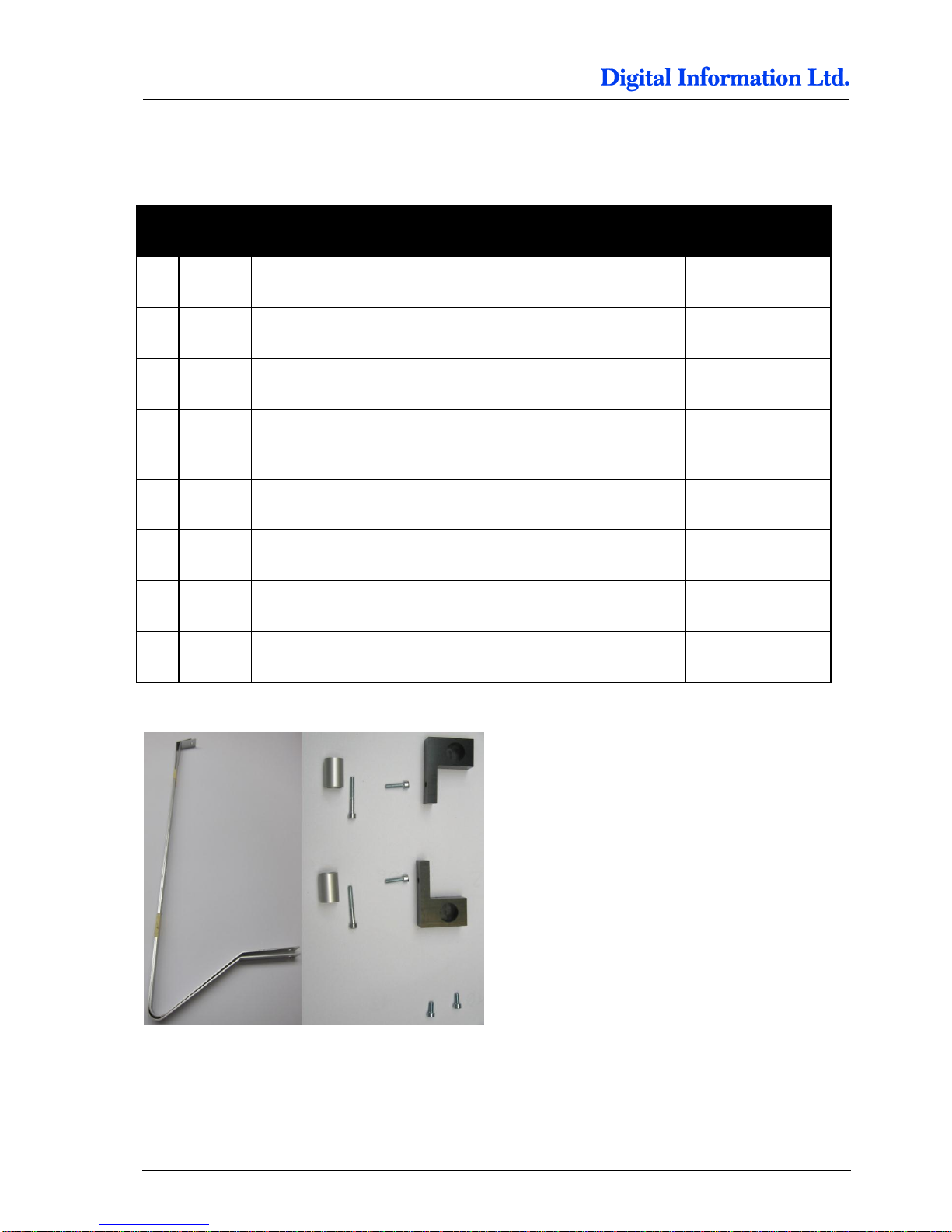
First mount the tube holder to the profile. Use the
inserted slot nuts and the M5 x 20 screws.
Put the paper guide tube into the holders right and
left.
Distance from the “side frame” to the “tube holders”,
measured from left side to left side is 425 mm.
Distance from the left “tube holder” to the right “tube
holder” is approx. 1205 mm.
Note:
The tube should rotate freely.
425 mm
Approx.1205 mm
Page 80
9
Paper Guide / Camera System
Add Paper Guide and Paper Tension Parts
9-16 Preproofer x700 / x900 – HW Installation Manual
9.9.3 Mount the Paper Tension Guide
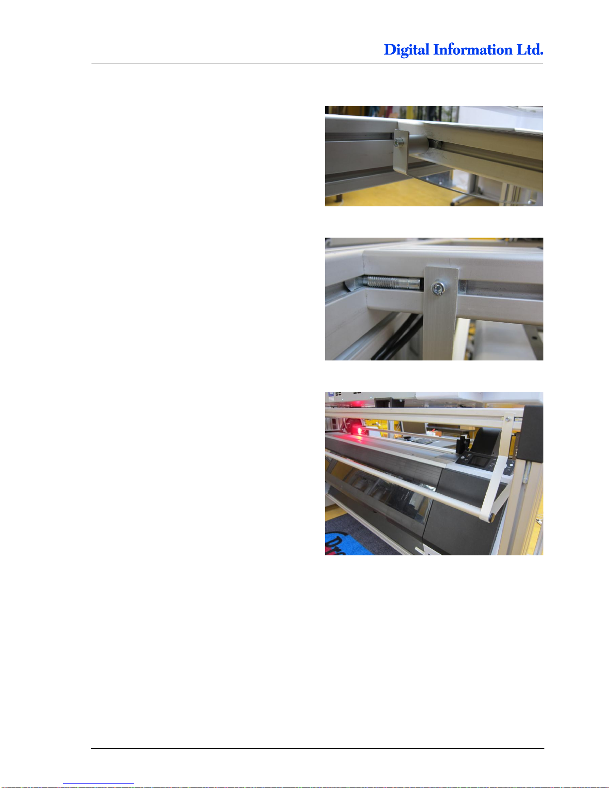
Use the M5 x 40 screws with the short aluminum
tube to fix the guide to the profile.
Mount the end of the guide to the slot nut in the
second profile. Use the M5 x 10 screws.
Do the same on the opposite side.
Fully mounted Paper Tension guide.
Page 81
Paper Guide / Camera System
Camera and Bar Light on Back Printer
9
Preproofer x700 / x900 – HW Installation Manual 9-17
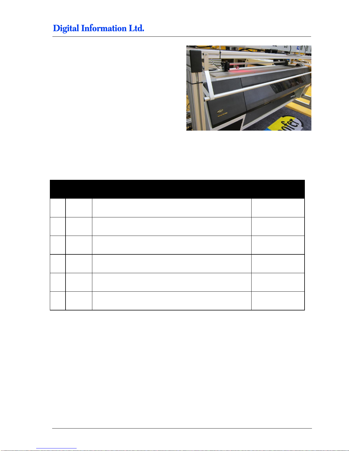
Fully mounted Paper Tension guide.
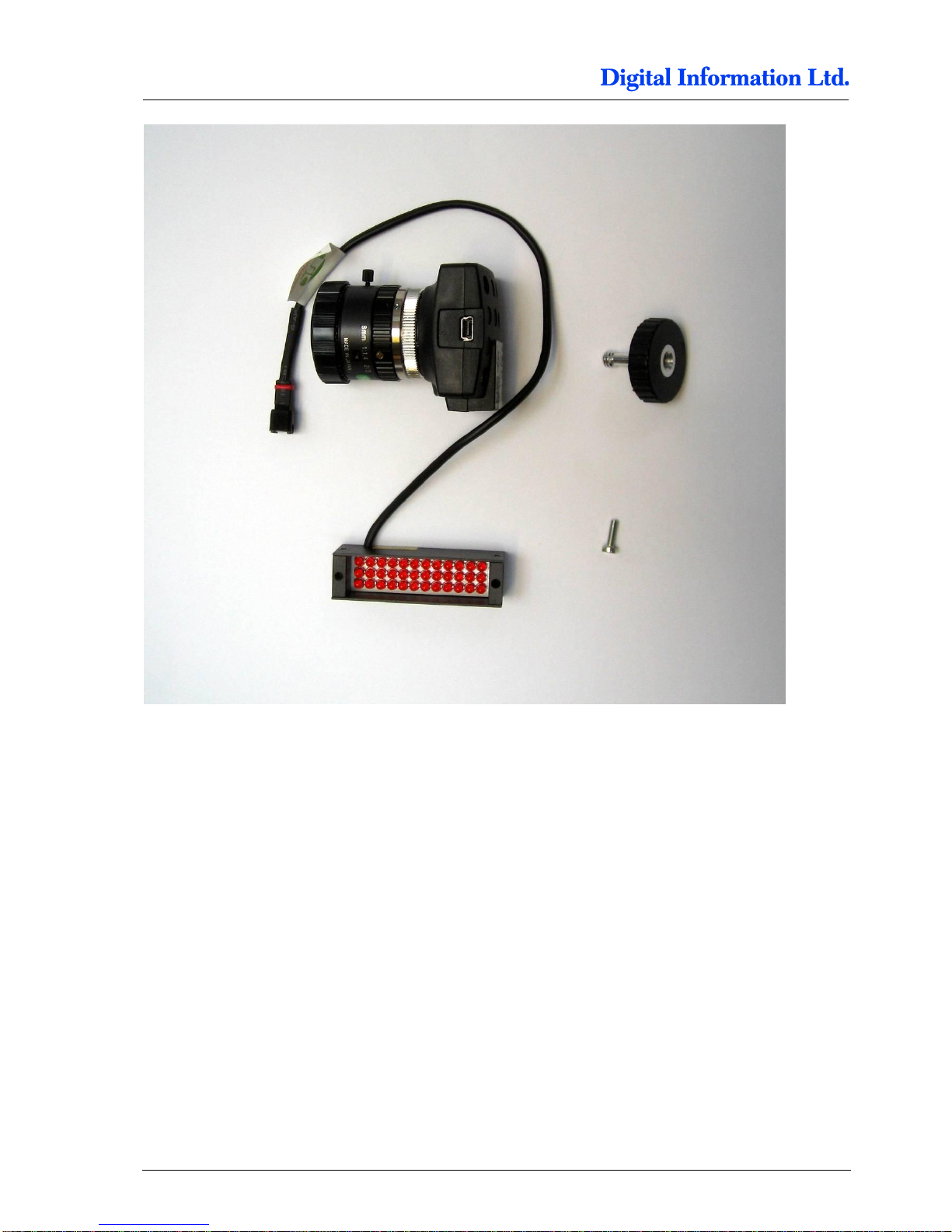
9.10 Camera and Bar Light on Back Printer
9.10.1 Additional Parts
Pos Amount
Name
Dimension in mm
71 1
Screw M3 x 10 with M4 washer
72 1 Screw for Camera
73 1 Camera
74 1 Lens
75 1 Ring distance holder
76 1 LED Bar Light, red
Page 82
9
Paper Guide / Camera System
Camera and Bar Light on Back Printer
9-18 Preproofer x700 / x900 – HW Installation Manual
Page 83
Paper Guide / Camera System
Camera and Bar Light on Front Printer
9
Preproofer x700 / x900 – HW Installation Manual 9-19
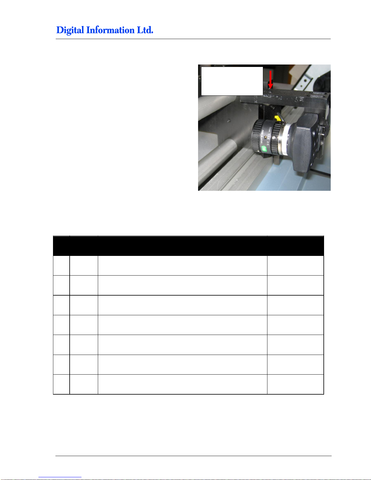
9.10.2 Mount Camera and LED Bar Light
Mount first the LED Bar Light; use the M3x10 screw
to fix it to the holder.
Set the focus on the lens to “Close Up” and the
aperture to approx 8.
Mount the camera.
9.11 Camera and Bar Light on Front Printer
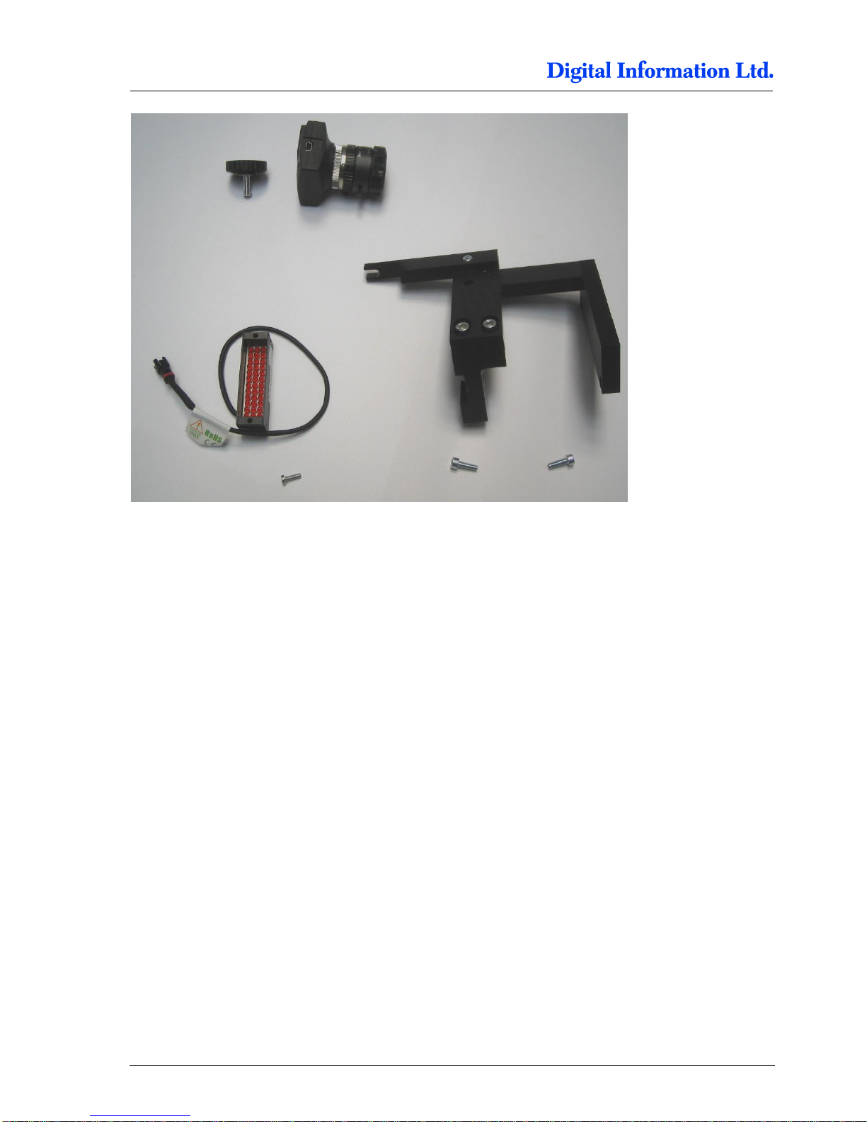
9.11.1 Additional Parts
Pos Amount
Name
Dimension in mm
71 1
Screw M3 x 10 with M3 washer
72 1 Screw for Camera
73 1 Camera
74 1 Lens
75 1 Ring distance holder
76 1 LED Bar Light, red
77 2 Screw M4 x 16
Hole to fix the LED
Bar Light to the
holder
Page 84
9
Paper Guide / Camera System
Camera and Bar Light on Front Printer
9-20 Preproofer x700 / x900 – HW Installation Manual
9.11.2 Mount LED Bar Light to holder
Mount first the LED Bar Light with the M3 x 10
screw to the holder. Place the M4 washer between
the LED Bar Light and the holder.
9.11.3 Mount the holder to Front printer
Use the two M4 x 16 screws to mount the holder to
the front printer. Use the holes from the spectro
scan module on the right hand side.
Page 85
Paper Guide / Camera System
Paper Bow for Back Printer
9
Preproofer x700 / x900 – HW Installation Manual 9-21
9.11.4 Mount the Camera
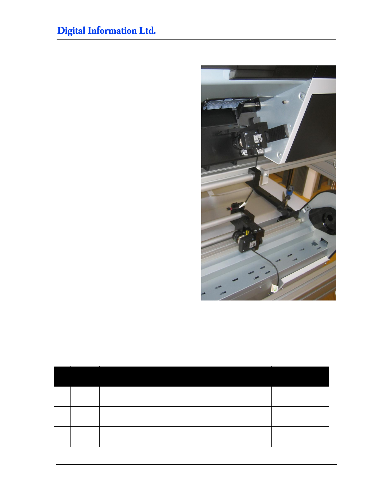
Mount the camera.
Set the focus on the lens to “Close Up” and the
aperture to approx. 8.
Mount the camera.
9.12 Paper Bow for Back Printer
9.12.1 Additional Parts
Pos Amount
Name
Dimension in mm
78 1
Screw M4 x 10
79 1 Aluminum bracket
80 1 Washer M4 or similar
Page 86
9
Paper Guide / Camera System
Paper Bow for Back Printer
9-22 Preproofer x700 / x900 – HW Installation Manual
81 1 Screw with big head
11 1 Distance holder back
82 1 M5 slot nut, thin type
9.12.2 Assembly
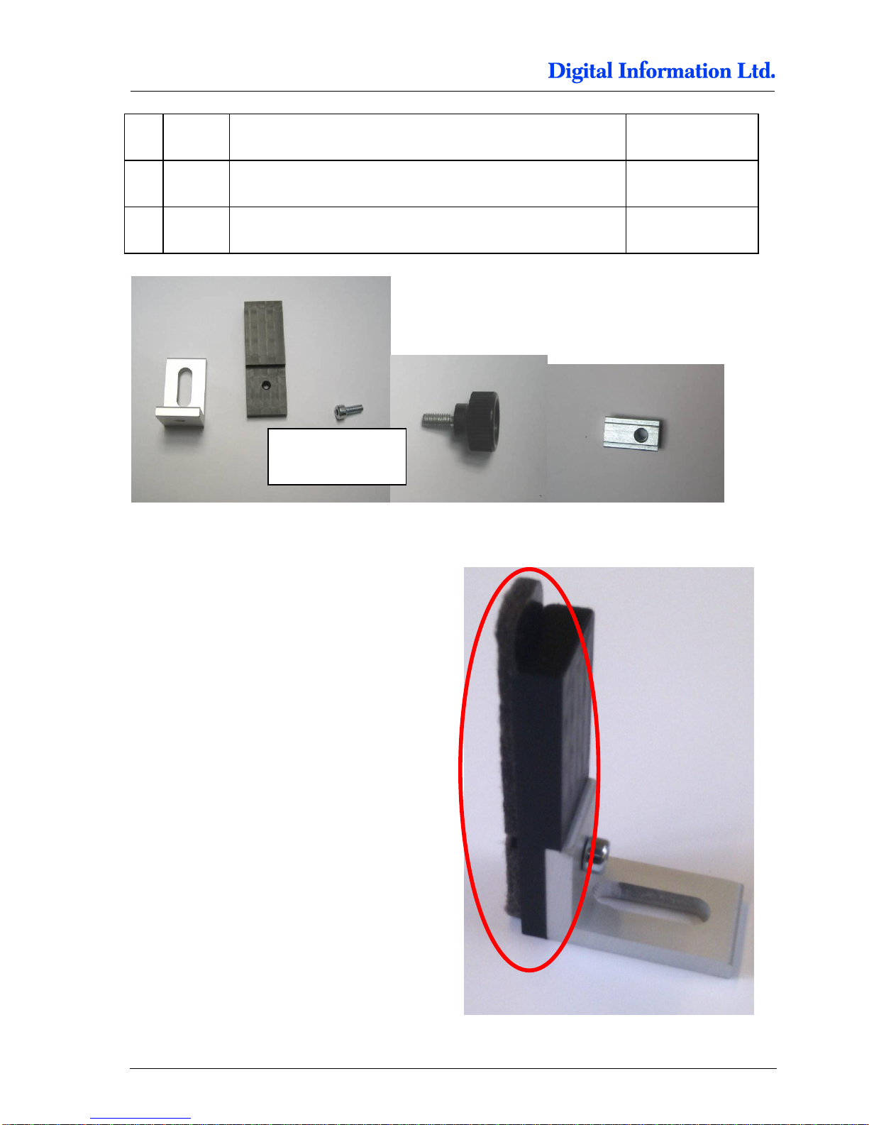
Put the screw with the big head through the bracket.
Then mount the holder with the M4 screw to the
bracket. Mount the felt.
Screw M4 x 10,
black with flat head
Page 87
Paper Guide / Camera System
Paper Bow for Front Printer
9
Preproofer x700 / x900 – HW Installation Manual 9-23
9.12.3 Assembly to the Profile
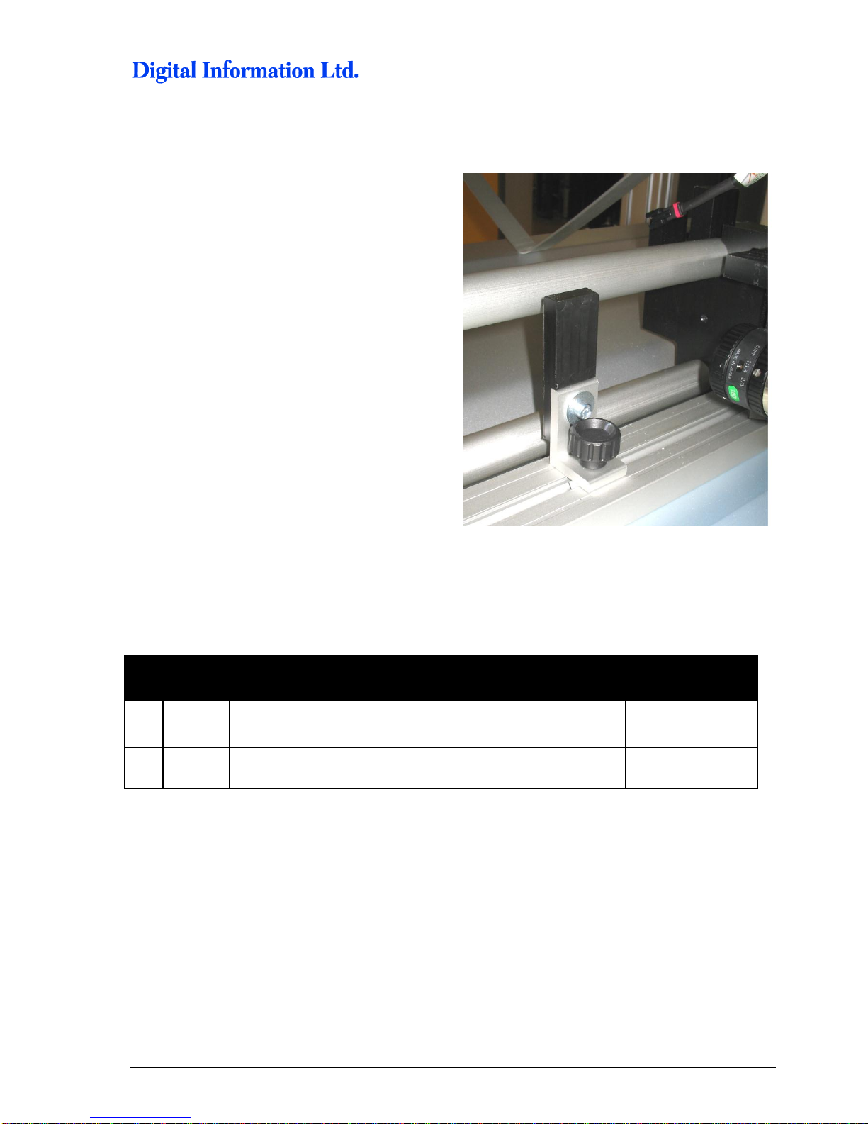
Insert the slot nut into the profile and screw the
distance holder on it.
9.13 Paper Bow for Front Printer
9.13.1 Additional Parts
Pos Amount
Name
Dimension in mm
83 1 Screw with big head
13 1 Distance holder front
Page 88
9
Paper Guide / Camera System
Paper Bow for Front Printer
9-24 Preproofer x700 / x900 – HW Installation Manual
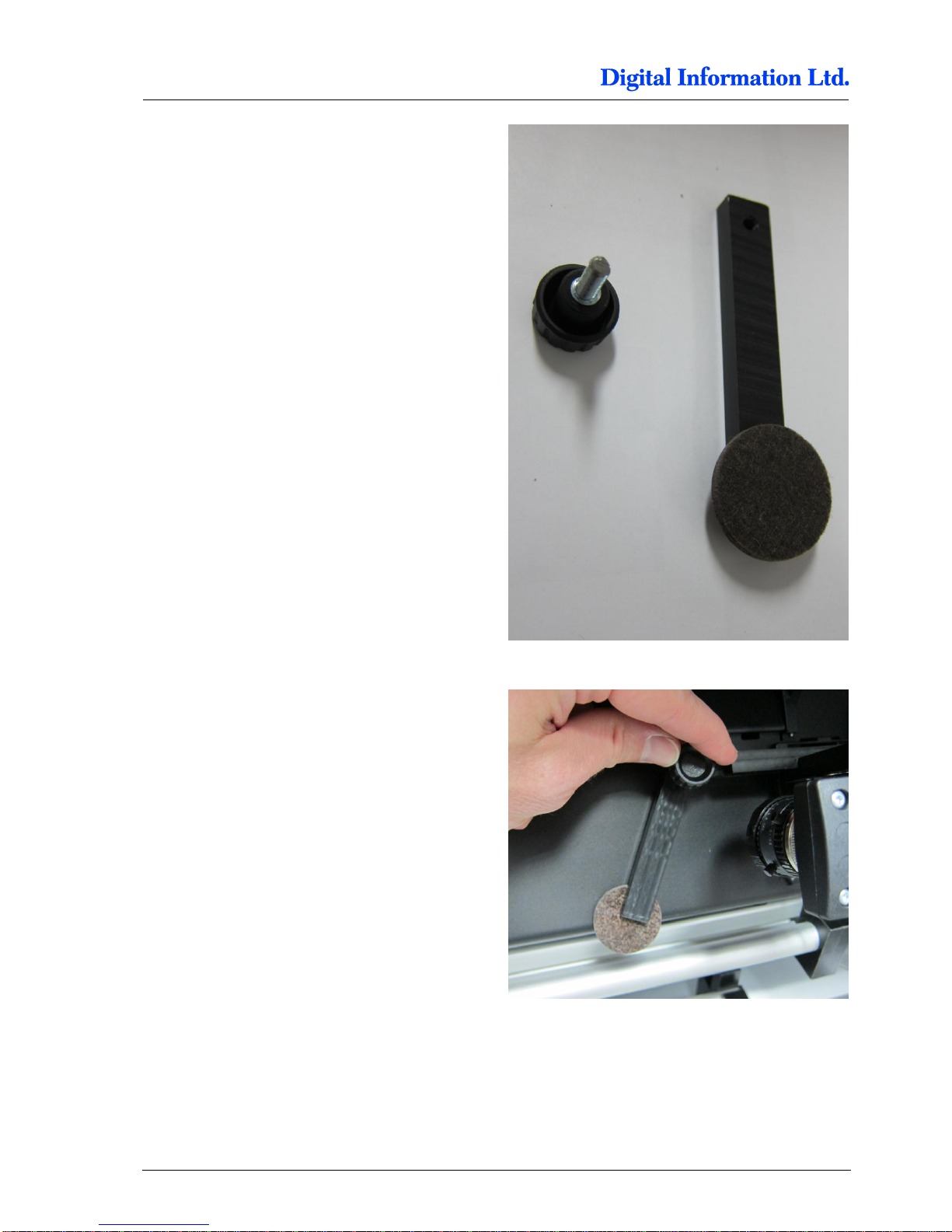
Mount the bow to the camera holder on the Front
printer.
Page 89
Paper Guide / Camera System
Mount the Electronic Box
9
Preproofer x700 / x900 – HW Installation Manual 9-25
9.14 Mount the Electronic Box
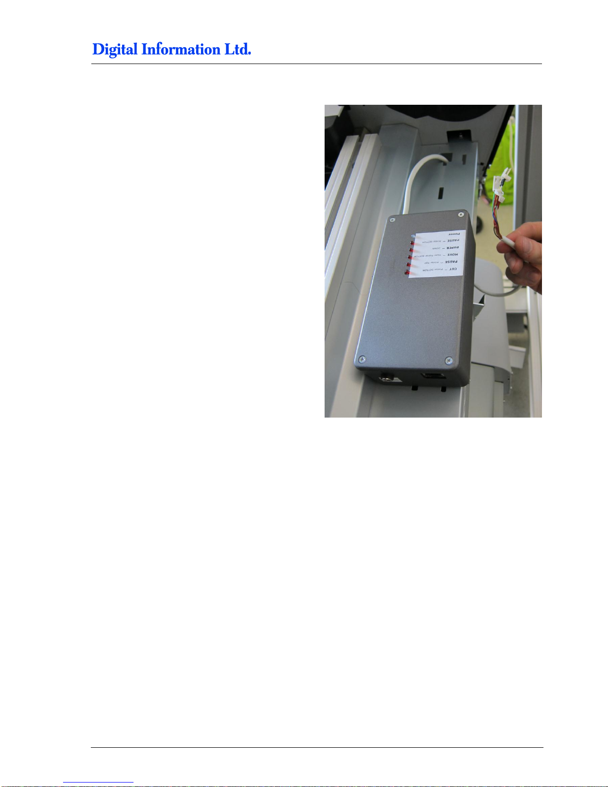
Mount the box with the Velcro tape to the printer.
Pull the cables through the hole to the PCB board.
9.15 Align the Printers
9.15.1 Paper Path
To align the two printers for the paper path, print the
test job “Job for Printer Alignment FRONTBACK.PRN”.
Use the “Print File Sender” program to send the job
into the Front Printer Queue. The program is located
under Start, Program, DI, DI-Pilot, Utilities.
Page 90
9
Paper Guide / Camera System
Align the Printers
9-26 Preproofer x700 / x900 – HW Installation Manual
To align the two printers for the paper path, print the
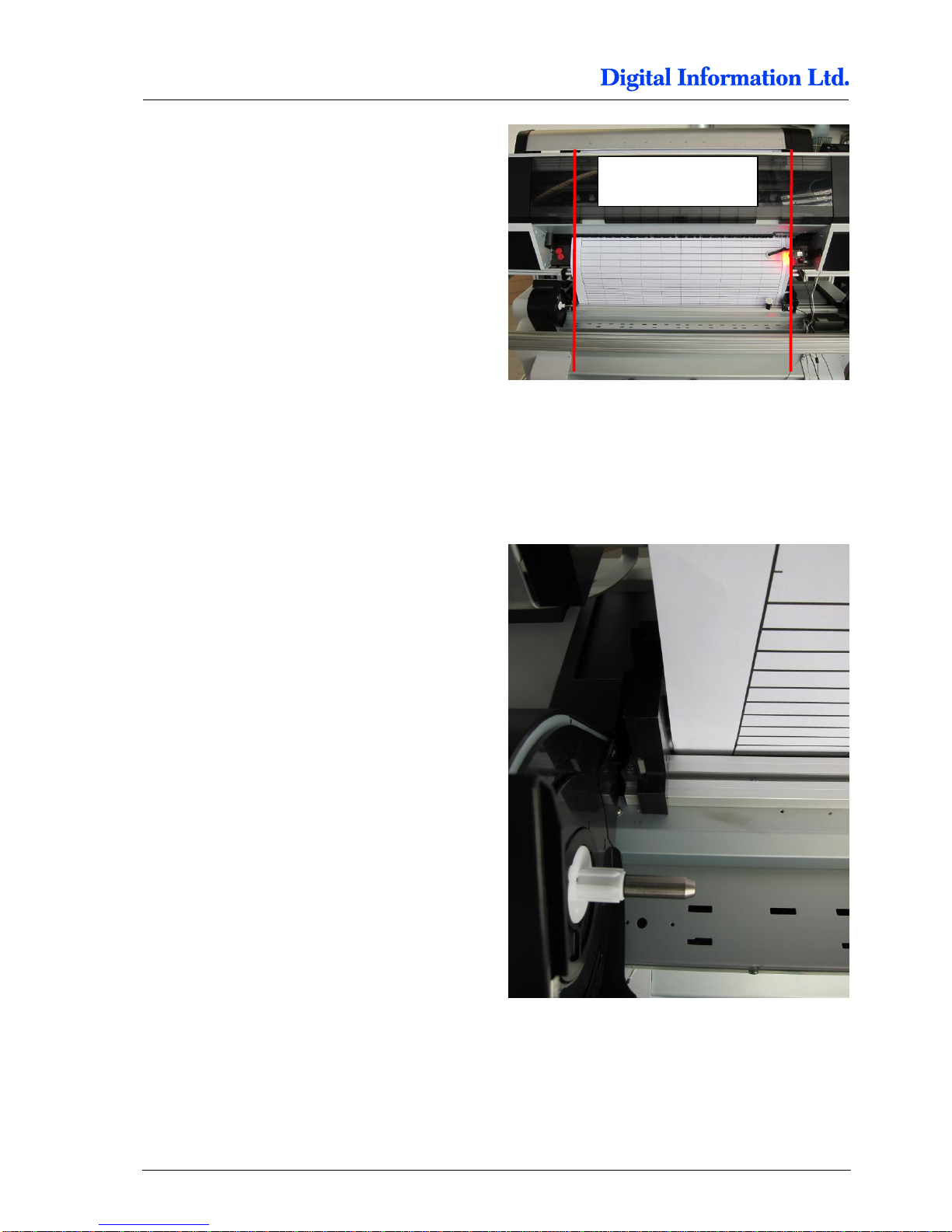
test job “Job for Printer Alignment FRONTBACK.prn”. The print job, a prn file, is located in a
programs subfolder called “Testjob”.
Use the “Print File Sender” program to send the job
into the Front Printer Queue. The program is located
under Start, Program, DI, DI-Pilot, Utilities.
Feed the paper coming from the Front printer
through the Back printer.
Consult the “PaperLoading Guide” for feeding the
paper from Top Printer to the Back Printer. PDF is
available in the PDF manuals folder.
Check the Paper edge on the left side. It needs to
pass the mark on the Back printer a bit to the right
side, approx. 1mm.
Alignement left / right
Page 91
Paper Guide / Camera System
Align the Printers
9
Preproofer x700 / x900 – HW Installation Manual 9-27
9.15.2 Parallel Alignment Front Printer
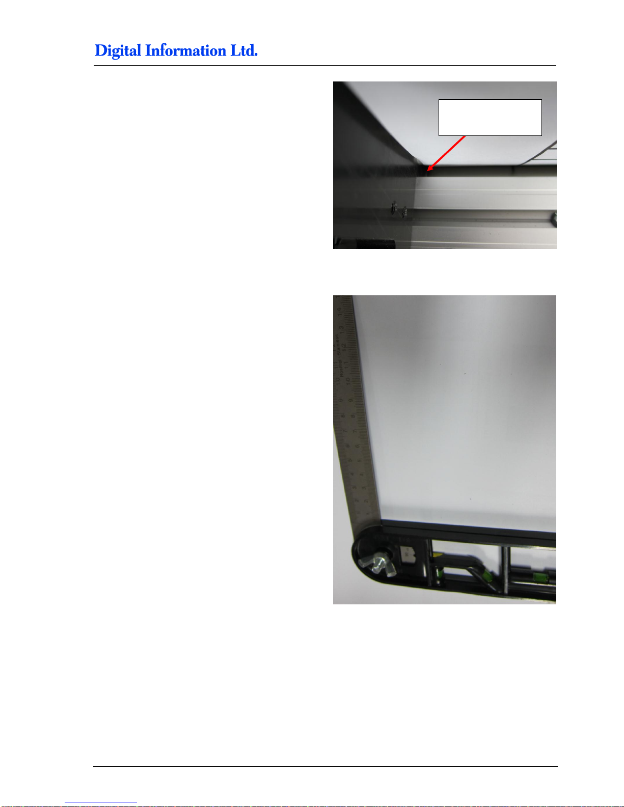
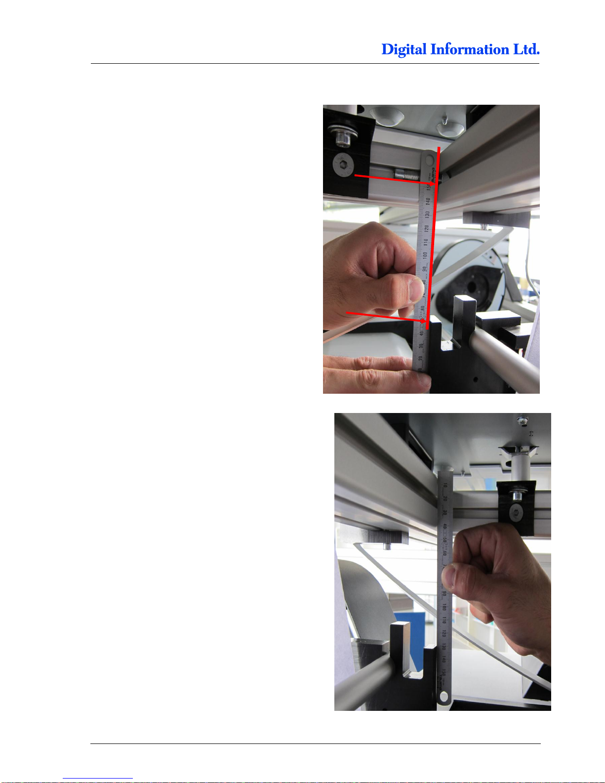
To align the printers, use an angle tool like shown.
Mark for Paper
Edge
Page 92
9
Paper Guide / Camera System
Align the Printers
9-28 Preproofer x700 / x900 – HW Installation Manual
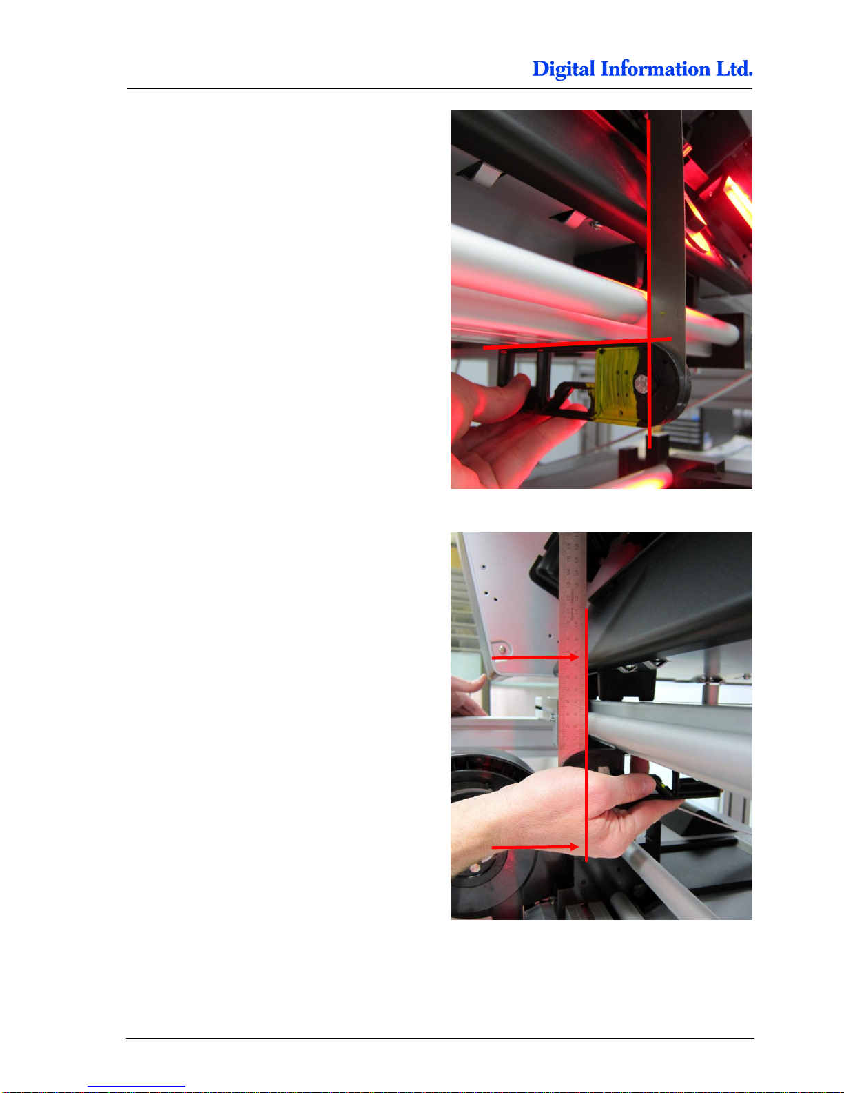
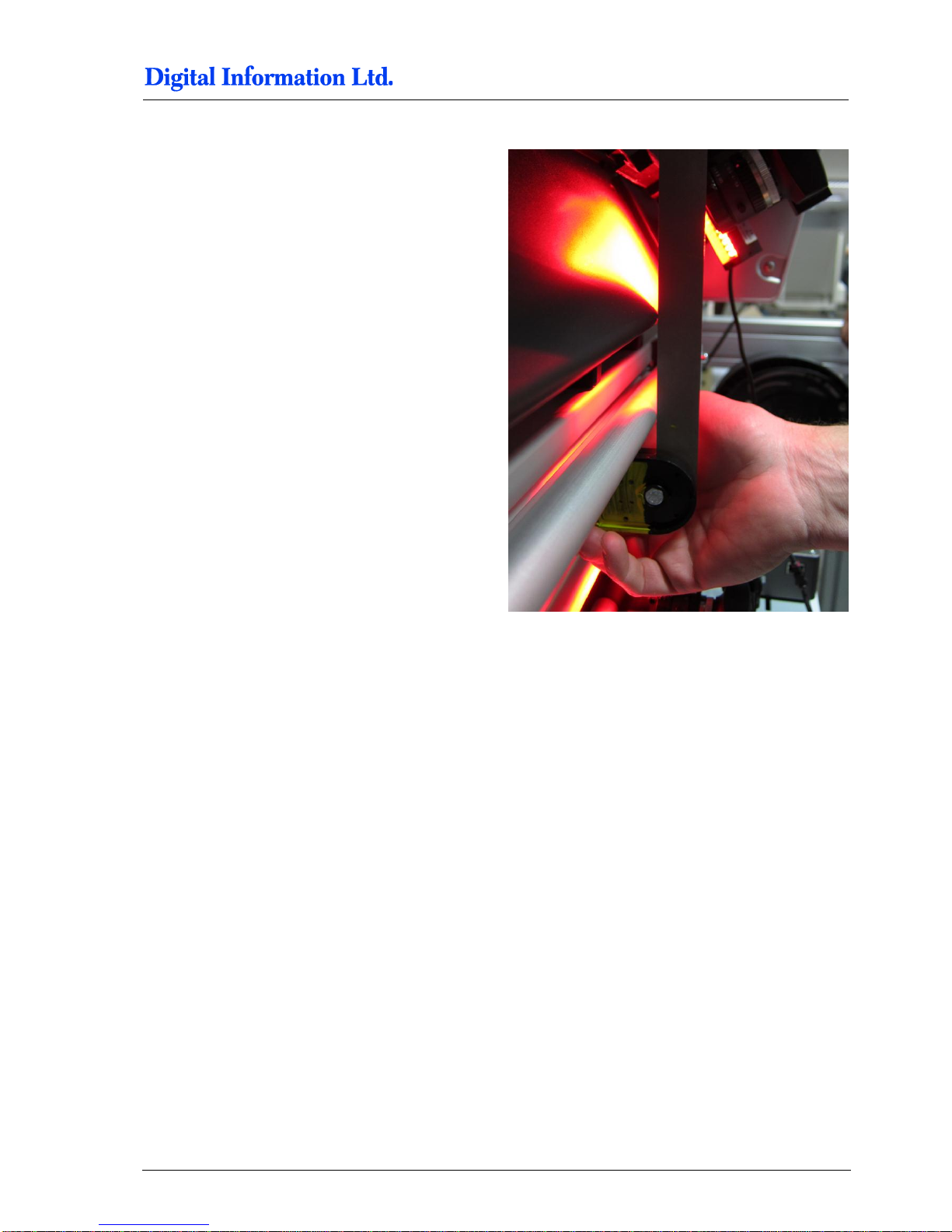
Align the edge from the Front printer with the roller.
The printer edge and the bar are inline.
Line-up on the left side.
Page 93
Paper Guide / Camera System
Align the Printers
9
Preproofer x700 / x900 – HW Installation Manual 9-29
Line-up on the right side.
Page 94
9
Paper Guide / Camera System
Align the Printers
9-30 Preproofer x700 / x900 – HW Installation Manual
9.15.3 Parallel Alignment Back Printer
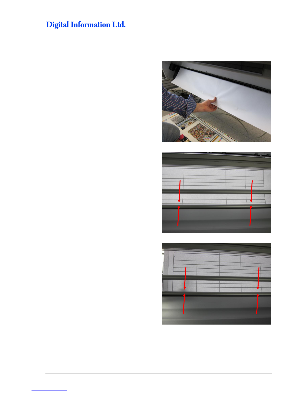
Align the lower printer parallel to the frame by
checking the edge of the tube holder with the frame.
Frame and tube holder are in line.
Do the same on the other side.
Page 95
Paper Guide / Camera System
Align the Printers
9
Preproofer x700 / x900 – HW Installation Manual 9-31
9.15.4 Horizontal Alignment
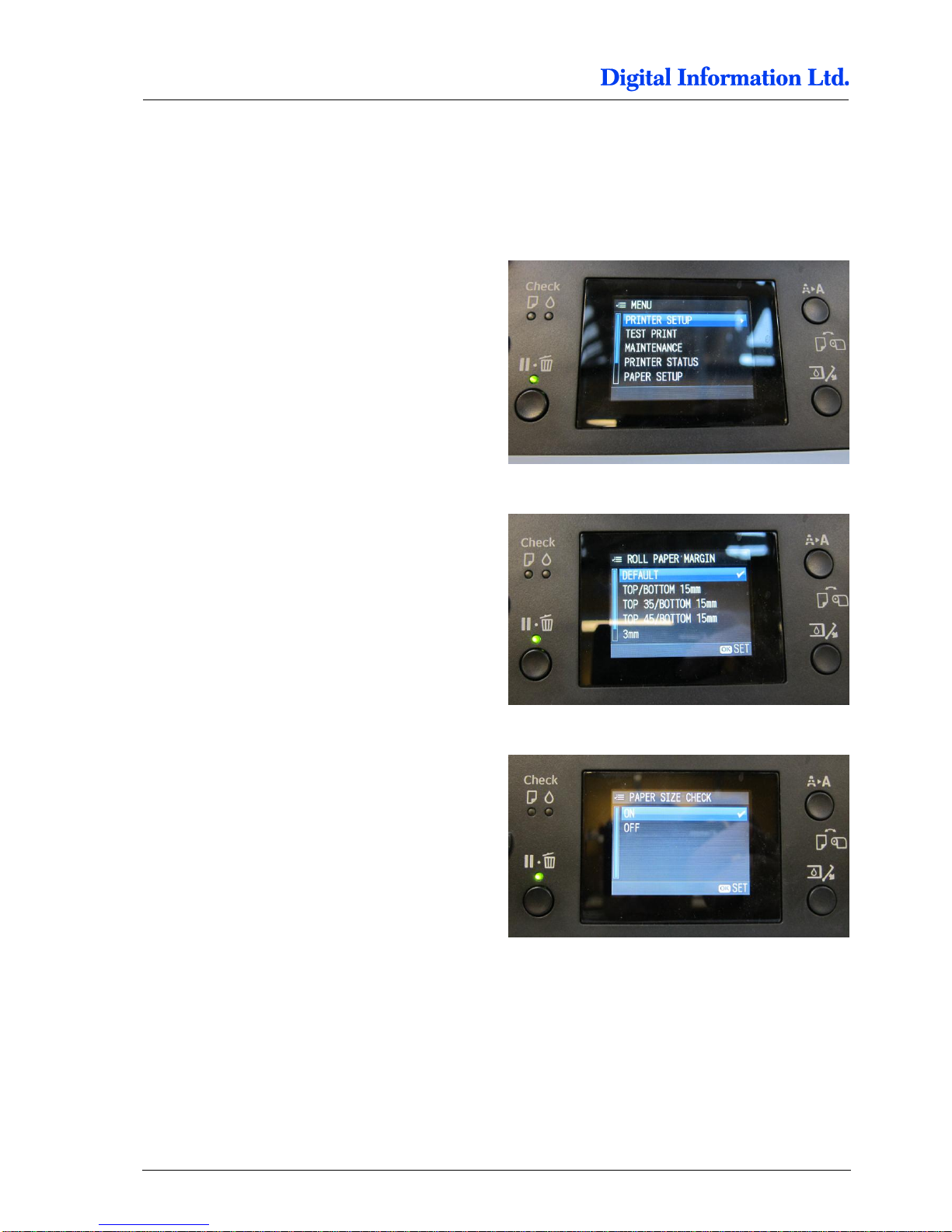
With the test job, it’s very simple to check the
horizontal alignment.
Pull the paper down
Look at the lines and the tubes. They need to be
perfectly parallel, from right to left and…
from left to right!
If corrections are needed, use the delivered 1,5mm
aluminum plates to put them below the printer stand.
For smaller changes use a washer instead.
Page 96
10
Printer Panel Configuration
Parameter Setup TOP and BOTTOM printer
10-32 Preproofer x700 / x900 – HW Installation Manual
10 Printer Panel Configuration
10.1 Parameter Setup TOP and BOTTOM printer
On the printer panel, go into the main “Menu” and
select “Printer Setup”.
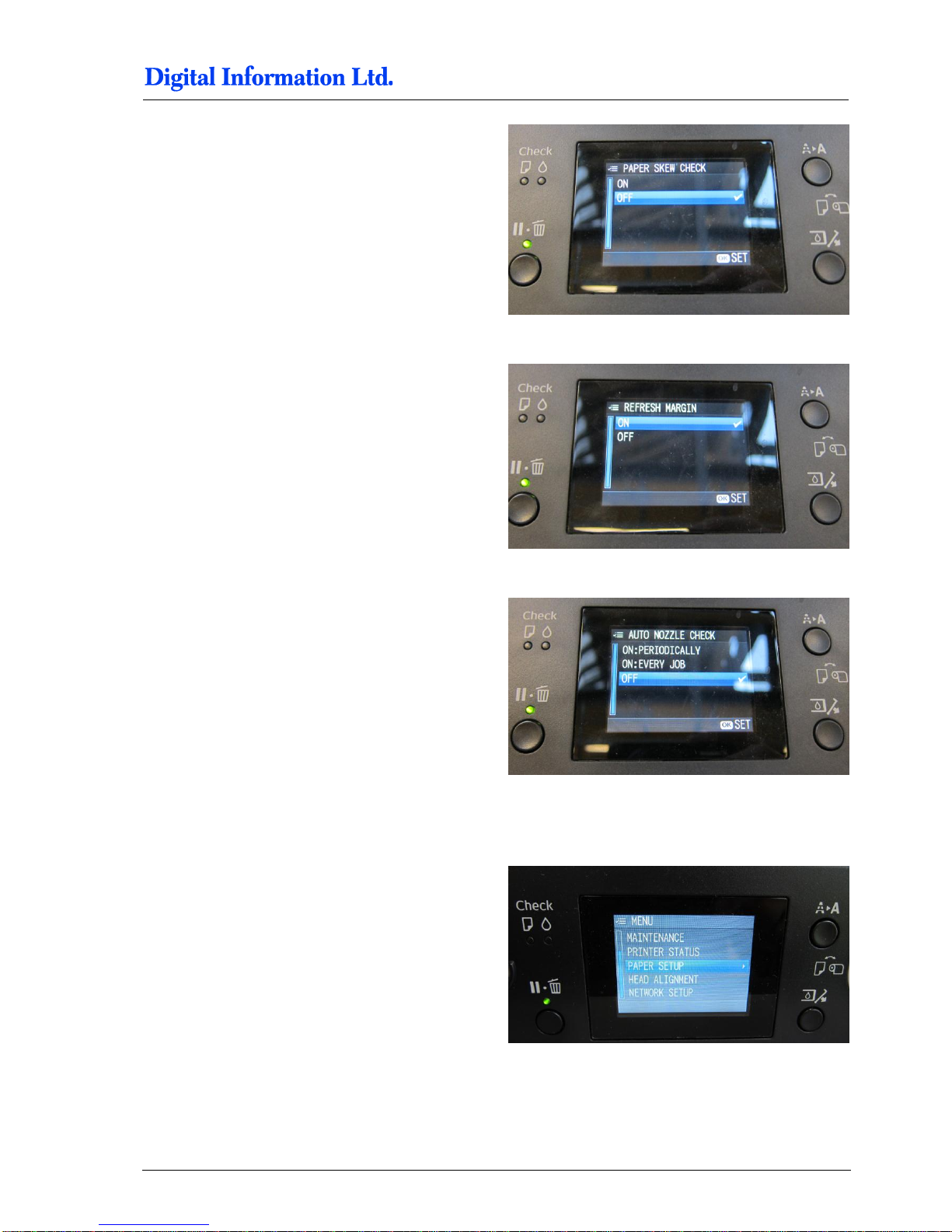
Open the entry “Roll Paper Margin” and select
“DEFAULT”.
Open the entry “Paper Size Check” and select “ON”.
Page 97
Printer Panel Configuration
Parameter Setup TOP and BOTTOM printer
10
Preproofer x700 / x900 – HW Installation Manual 10-33
Open the entry “Paper Skew Check” and select
“OFF”.
Open the entry “Refresh Margin” and select “ON”.
Open the entry “Auto Nozzle Check” and select
“OFF”.
10.1.1 TOP Printer - Configure Custom Paper 1
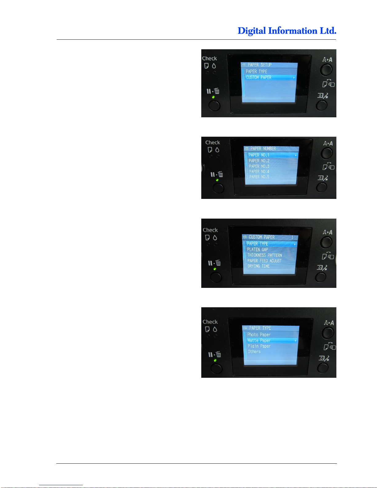
On the printer panel, go into the main “Menu” and
select “Paper Setup”.
Page 98
10
Printer Panel Configuration
Parameter Setup TOP and BOTTOM printer
10-34 Preproofer x700 / x900 – HW Installation Manual
Select “Custom Paper”.
Select “Paper NO.1”.
Select “Paper TYPE”.
Select “Matte Paper”.
Page 99
Printer Panel Configuration
Parameter Setup TOP and BOTTOM printer
10
Preproofer x700 / x900 – HW Installation Manual 10-35
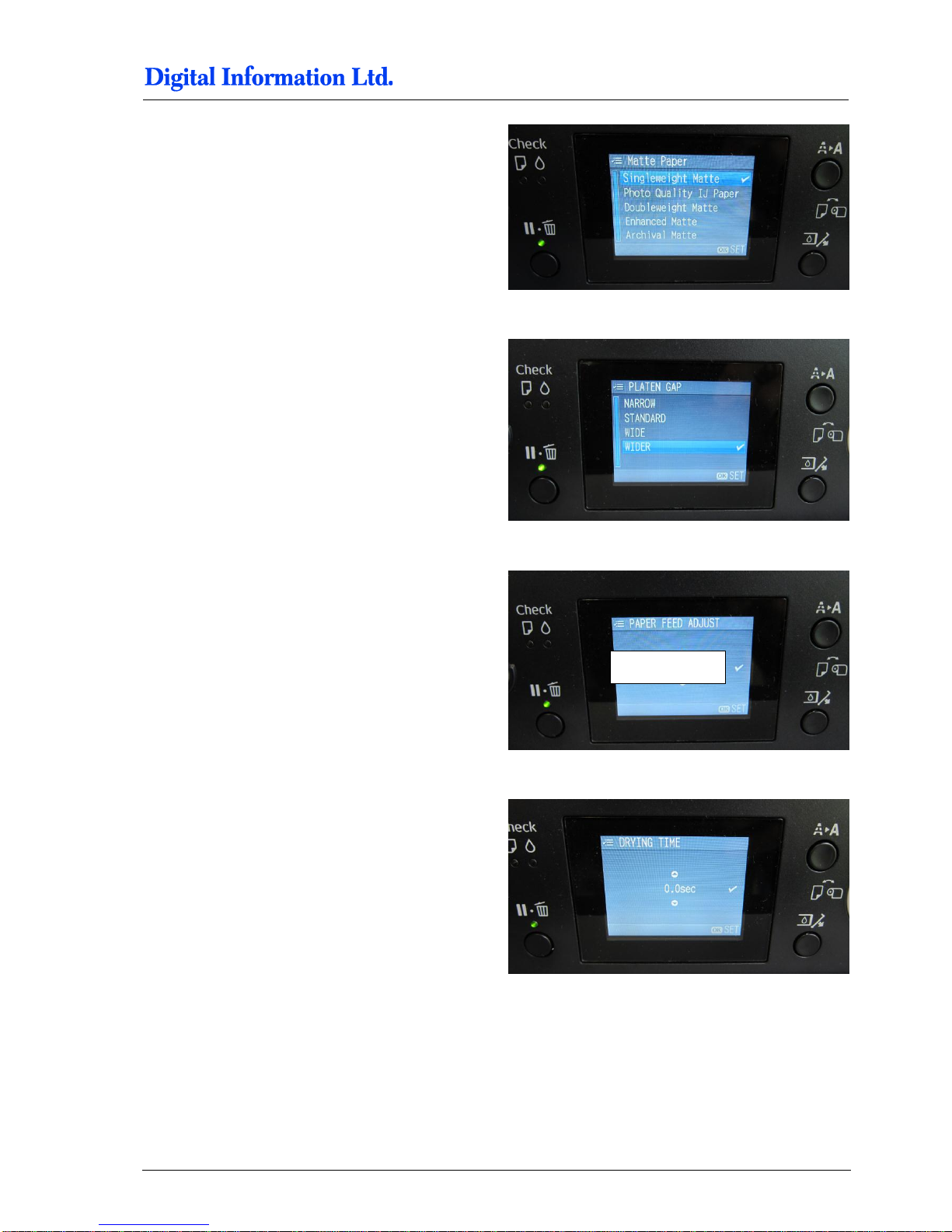
Select “Singleweight Matte”.
Stay in the “Paper NO.1” “, open the entry “Platen
GAP” and select “WIDER”.
Stay in the “Paper NO.1” “, open the entry “Paper
Feed Adjust” and select “+0.0%”.
Stay in the “Paper NO.1” “, open the entry “Drying
Time” and select “0.0sec”.
0,0 %
Page 100
10
Printer Panel Configuration
Parameter Setup TOP and BOTTOM printer
10-36 Preproofer x700 / x900 – HW Installation Manual
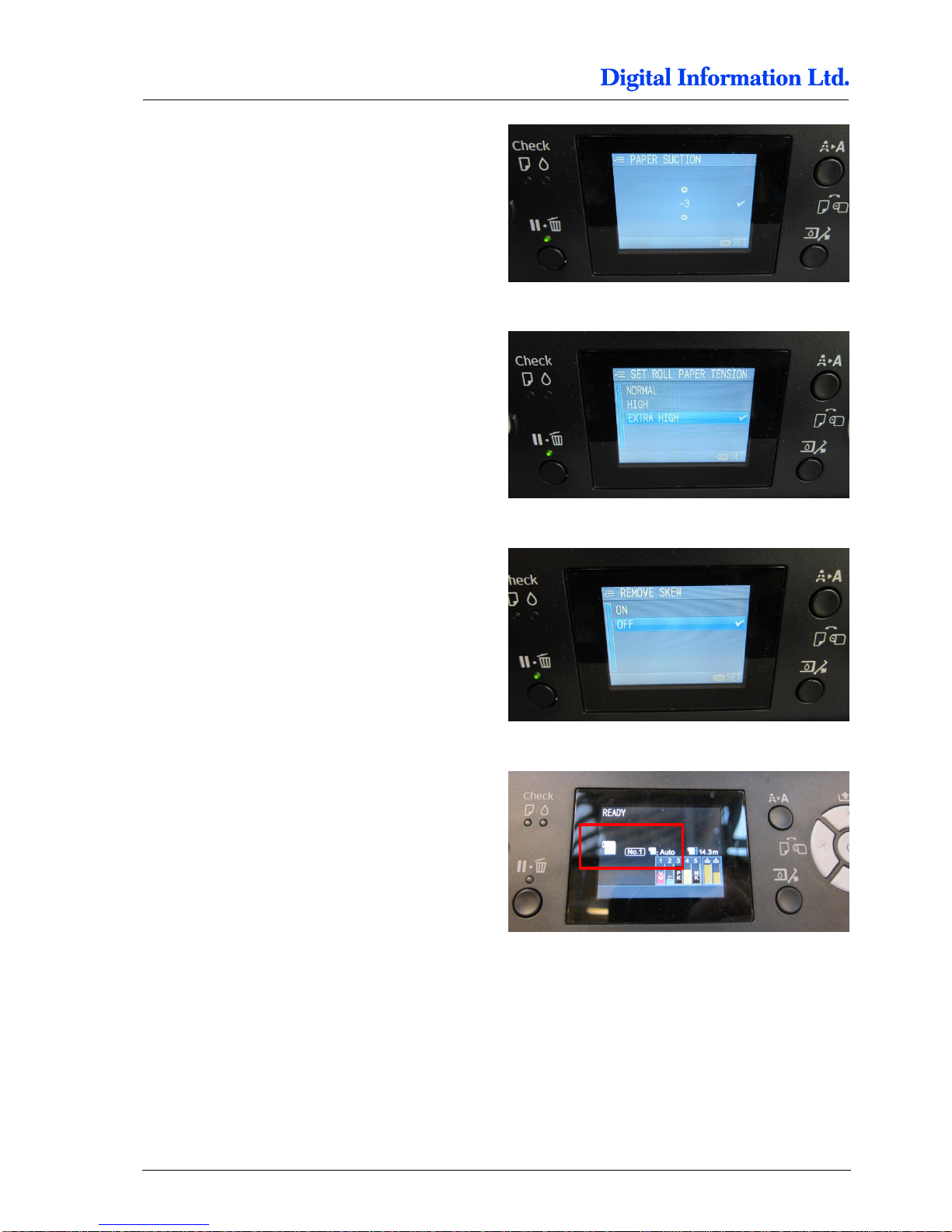
Stay in the “Paper NO.1” “, open the entry “Paper
Suction” and select “-3”.
Stay in the “Paper NO.1” “, open the entry “Set Roll
Paper Tension” and select “Extra High”.
Stay in the “Paper NO.1” “, open the entry “Remove
Skew” and select “OFF”.
Activate “Custom Paper NO.1” and select “Roll
Paper – No Cut”.
 Loading...