

Page 1

PantherPro/46 Image Recorder TP8251
Table of Contents
Section 1 General Service Information Page
1-1 Scope of Manual . . . . . . . . . . . . . . . . . . . . . . . . . . . . . . . . . . . . . . . . . . 1-1
1-2 Laser Information . . . . . . . . . . . . . . . . . . . . . . . . . . . . . . . . . . . . . . . . . . 1-2
1-3 Regulatory Agencies Information. . . . . . . . . . . . . . . . . . . . . . . . . . . . . . 1-3
1-4 Electrostatic Discharge - ESD . . . . . . . . . . . . . . . . . . . . . . . . . . . . . . . . 1-4
Section 2 Overview and Specifications
2-1 System Overview . . . . . . . . . . . . . . . . . . . . . . . . . . . . . . . . . . . . . . . . . . 2-1
2-2 Hardware Overview . . . . . . . . . . . . . . . . . . . . . . . . . . . . . . . . . . . . . . . . 2-2
2-3 Electrical Power Requirements . . . . . . . . . . . . . . . . . . . . . . . . . . . . . . . 2-9
2-4 Product Specifications . . . . . . . . . . . . . . . . . . . . . . . . . . . . . . . . . . . . . 2-10
Section 3 Theory of Operation
3-1 PantherPro/46 Image Recorder Overview. . . . . . . . . . . . . . . . . . . . . . . 3-1
3-2 Big Output Board (BOB) . . . . . . . . . . . . . . . . . . . . . . . . . . . . . . . . . . . . 3-3
3-3 High Speed Laser Amplifier (HSLA) PCB . . . . . . . . . . . . . . . . . . . . . . 3-11
3-4 High Speed Laset Driver PCB/Laser Tube Assmbly . . . . . . . . . . . . . . 3-12
3-5 Graphics LCD/Keypad Assembly and Backlight Inverter PCB . . . . . . 3-13
3-6 Media Transport .. . . . . . . . . . . . . . . . . . . . . . . . . . . . . . . . . . . . . . . . . 3-13
3-7 Optical System. . . . . . . . . . . . . . . . . . . . . . . . . . . . . . . . . . . . . . . . . . . 3-18
3-8 Sensors and Switches . . . . . . . . . . . . . . . . . . . . . . . . . . . . . . . . . . . . . 3-20
Section 4 Power Supply and Distribution
4-1 AC Power. . . . . . . . . . . . . . . . . . . . . . . . . . . . . . . . . . . . . . . . . . . . . . . . 4-1
4-2 DC Power. . . . . . . . . . . . . . . . . . . . . . . . . . . . . . . . . . . . . . . . . . . . . . . . 4-3
Section 5 Installation
5-1 Bill of Materials. . . . . . . . . . . . . . . . . . . . . . . . . . . . . . . . . . . . . . . . . . . . 5-1
5-2 Pre-Installation Procedure . . . . . . . . . . . . . . . . . . . . . . . . . . . . . . . . . . . 5-1
5-3 Electrical Requirements . . . . . . . . . . . . . . . . . . . . . . . . . . . . . . . . . . . . . 5-1
5-4 Installation Procedure . . . . . . . . . . . . . . . . . . . . . . . . . . . . . . . . . . . . . . 5-2
5-5 System Test . . . . . . . . . . . . . . . . . . . . . . . . . . . . . . . . . . . . . . . . . . . . . . 5-3
5-6 Installation Completion. . . . . . . . . . . . . . . . . . . . . . . . . . . . . . . . . . . . . . 5-4
PrePRESS SOLUTIONS CONFIDENTIAL
i October 1995
Page 2

TP8251
Section 6 Maintenance Page
6-1 Periodic Maintenance . . . . . . . . . . . . . . . . . . . . . . . . . . . . . . . . . . . . . . 6-1
6-2 Optics Cleaning Procedures . . . . . . . . . . . . . . . . . . . . . . . . . . . . . . . . . 6-1
6-3 Adjustable Clutch . . . . . . . . . . . . . . . . . . . . . . . . . . . . . . . . . . . . . . . . . 6-6
6-4 Safety Considerations . . . . . . . . . . . . . . . . . . . . . . . . . . . . . . . . . . . . . 6-9
Section 7 Removal/Replacement Page
7-1 External Covers and Panels . . . . . . . . . . . . . . . . . . . . . . . . . . . . . . . . . 7-1
7-2 Page Buffer Module(s) . . . . . . . . . . . . . . . . . . . . . . . . . . . . . . . . . . . . . . 7-5
7-3 Big OutPut Board/Wide Controller PCB. . . . . . . . . . . . . . . . . . . . . . . . . 7-5
7-4 Page Buffer (PB) Disk Drives. . . . . . . . . . . . . . . . . . . . . . . . . . . . . . . . . 7-6
7-5 LCD and Terminator PCB . . . . . . . . . . . . . . . . . . . . . . . . . . . . . . . . . . . 7-6
7-6 LCD Inverter PCB . . . . . . . . . . . . . . . . . . . . . . . . . . . . . . . . . . . . . . . . . 7-6
7-7 Polygon Driver PCB/Motor Assembly . . . . . . . . . . . . . . . . . . . . . . . . . . 7-7
7-8 Zenith ZPS-300 Power Supply. . . . . . . . . . . . . . . . . . . . . . . . . . . . . . . . 7-7
7-9 Condor Power Supply . . . . . . . . . . . . . . . . . . . . . . . . . . . . . . . . . . . . . . 7-8
7-10 Cooling Fan Assembly . . . . . . . . . . . . . . . . . . . . . . . . . . . . . . . . . . . . . . 7-8
7-11 High Speed Laser Amplifier PCB. . . . . . . . . . . . . . . . . . . . . . . . . . . . . . 7-8
7-12 Laser Fan (Retrofit Kit) Assembly . . . . . . . . . . . . . . . . . . . . . . . . . . . . . 7-8
7-13 Start Of Line Amplifier/Sensor PCB . . . . . . . . . . . . . . . . . . . . . . . . . . . . 7-9
7-14 High Speed Lased Driver/Laser Tube Assembly. . . . . . . . . . . . . . . . . . 7-9
7-15 Second Cylinder Lens Assembly . . . . . . . . . . . . . . . . . . . . . . . . . . . . . 7-10
7-16 Scan Lens . . . . . . . . . . . . . . . . . . . . . . . . . . . . . . . . . . . . . . . . . . . . . . 7-12
7-17 Gate Assembly. . . . . . . . . . . . . . . . . . . . . . . . . . . . . . . . . . . . . . . . . . . 7-13
7-18 Drag-Pinch Roller. . . . . . . . . . . . . . . . . . . . . . . . . . . . . . . . . . . . . . . . . 7-14
7-19 Drive Pinch Roller . . . . . . . . . . . . . . . . . . . . . . . . . . . . . . . . . . . . . . . . 7-15
7-20 Gate Media Out Switch . . . . . . . . . . . . . . . . . . . . . . . . . . . . . . . . . . . . 7-15
7-21 Gate Punch Motor Home Switch . . . . . . . . . . . . . . . . . . . . . . . . . . . . . 7-15
7-22 Adjustable Clutch . . . . . . . . . . . . . . . . . . . . . . . . . . . . . . . . . . . . . . . . . 7-16
7-23 Drag Roller. . . . . . . . . . . . . . . . . . . . . . . . . . . . . . . . . . . . . . . . . . . . . . 7-17
7-24 Drive Roller . . . . . . . . . . . . . . . . . . . . . . . . . . . . . . . . . . . . . . . . . . . . . 7-18
7-25 Knife Motor Assembly . . . . . . . . . . . . . . . . . . . . . . . . . . . . . . . . . . . . . 7-18
7-26 Knife Carriage Assembly . . . . . . . . . . . . . . . . . . . . . . . . . . . . . . . . . . . 7-19
7-27 Worm Gearbox Assembly . . . . . . . . . . . . . . . . . . . . . . . . . . . . . . . . . . 7-19
7-28 Leading Worm . . . . . . . . . . . . . . . . . . . . . . . . . . . . . . . . . . . . . . . . . . . 7-19
7-29 Servo Leading Motor/Encoder Assembly. . . . . . . . . . . . . . . . . . . . . . . 7-20
7-30 Leading Spur Gear . . . . . . . . . . . . . . . . . . . . . . . . . . . . . . . . . . . . . . . 7-20
PantherPro/46 Image Recorder
ii October 1995
PrePRESS SOLUTIONS CONFIDENTIAL
Page 3

PantherPro/46 Image Recorder TP8251
Section 8 Referenve/Adjustments Page
8-1 Component Locations . . . . . . . . . . . . . . . . . . . . . . . . . . . . . . . . . . . . . . 8-1
8-2 PCB Reference/Adjustments(Jumpers, LEDs, Switches, etc. ). . . . . . . 8-2
8-3 Page Buffer Disk Drive Jumpers . . . . . . . . . . . . . . . . . . . . . . . . . . . . . 8-10
8-4 Power Supply Jumpers/Adjustments . . . . . . . . . . . . . . . . . . . . . . . . . . 8-11
8-5 Take-up Cassette. . . . . . . . . . . . . . . . . . . . . . . . . . . . . . . . . . . . . . . . . 8-13
8-6 Supply Cassette. . . . . . . . . . . . . . . . . . . . . . . . . . . . . . . . . . . . . . . . . . 8-13
8-7 Clutch. . . . . . . . . . . . . . . . . . . . . . . . . . . . . . . . . . . . . . . . . . . . . . . . . . 8-15
8-8 Line Length and Leading . . . . . . . . . . . . . . . . . . . . . . . . . . . . . . . . . . . 8-16
8-9 Margin . . . . . . . . . . . . . . . . . . . . . . . . . . . . . . . . . . . . . . . . . . . . . . . . . 8-16
Section 9 Diagnostics
9-1 Panther Pro Software Overview (Pro Downloader) . . . . . . . . . . . . . . . . 9-1
9-2 PantherPro/46 Diagnostics Overview . . . . . . . . . . . . . . . . . . . . . . . . . . 9-6
9-3 PROM Resident Diagnostics . . . . . . . . . . . . . . . . . . . . . . . . . . . . . . . . . 9-9
9-4 Disk Resident Diagnostics (Debug Port) . . . . . . . . . . . . . . . . . . . . . . . 9-14
9-5 Front Panel Menu System . . . . . . . . . . . . . . . . . . . . . . . . . . . . . . . . . . 9-23
Section 10 Parts Listing
Explanatory . . . . . . . . . . . . . . . . . . . . . . . . . . . . . . . . . . . . . . . . . . . . . 10-2
Group 1 Covers, Doors, and Panels . . . . . . . . . . . . . . . . . . . . . . . . . . . . . . . . . 10-3
Group 2 Electronics Chassis . . . . . . . . . . . . . . . . . . . . . . . . . . . . . . . . . . . . . . . 10-6
Group 3 Optical Base Components . . . . . . . . . . . . . . . . . . . . . . . . . . . . . . . . . . 10-8
Group 4 Media Feed Transport . . . . . . . . . . . . . . . . . . . . . . . . . . . . . . . . . . . . 10-10
Group 5 Paper Feed Transport Drive . . . . . . . . . . . . . . . . . . . . . . . . . . . . . . . 10-14
Group 6 Cables and Harnesses. . . . . . . . . . . . . . . . . . . . . . . . . . . . . . . . . . . . 10-16
Group 7 Supply Cassette. . . . . . . . . . . . . . . . . . . . . . . . . . . . . . . . . . . . . . . . . 10-21
Group 8 Take-up Cassettes. . . . . . . . . . . . . . . . . . . . . . . . . . . . . . . . . . . . . . . 10-24
PrePRESS SOLUTIONS CONFIDENTIAL
iii October 1995
Page 4

TP8251
PantherPro/46 Image Recorder
iv October 1995
PrePRESS SOLUTIONS CONFIDENTIAL
Page 5

PantherPro/46 Image Recorder TP8251
PantherPro/46
Image Recorder
TECHNICAL MANUAL
PreliminaryPreliminary
TP8251
2
October 1995
PrePRESS SOLUTIONS CONFIDENTIAL
PrePRESS SOLUTIONS CONFIDENTIAL
v October 1995
Page 6

PantherPro/46 Image Recorder TP8251
Section 1 General Service Information
1-1 Scope of Manual
The "PantherPro/46 Image Recorder Technical Manual" is intended for the use of trained
technical representatives of PrePRESS Solutions Inc., its subsidiaries and dealers. It is not
intended as a substitute for training. Service personnel will utilize this document as a
resource for information to maintain the high imaging quality and performance of the
recorder.
Section 1: “General Service Information”, contains general information regarding the
technical manual, laser safety information, regulatory agencies information, and
electro-static discharge prevention rules.
Section 2: “Overview and Specifications”, contains a system overview and performance
specifications of the PantherPro/46 Imagesetting System.
Section 3: “Theory of Operation”, describes in detail the functionality of the PantherPro/46
image recorder.
Section 4: "Power Supply and Distribution", contains details regarding the AC and DC
power distribution of the PantherPro/46 image recorder.
Section 5: “Installation”, contains the installation instructions for the PantherPro/46
Imagesetting System.
Section 6: "Maintenance" contains the maintenance procedures for the PantherPro/46
image recorder.
Section 7: “Removal/Replacement”, contains removal/replacement procedures for field
serviceable electronic, optical, and mechanical components contained in the
PantherPro/46 image recorder.
Section 8: “Reference/Adjustments, contains reference material and adjustment
procedures for the PantherPro/46 image recorder that are useful in diagnosing
error conditions.
Section 9: “Diagnostics”, contains an overview of the PantherPro Software, Debug Port,
and Bomb Messages. Diagnostic test procedures normally performed on the
PantherPro/46 image recorder are also contained in this section.
Section 10: “Parts Listing”, contains a catalog which identifies part numbers of
the PantherPro/46 image recorder.
October 1995 PrePRESS SOLUTIONS CONFIDENTIAL 1-1
Page 7

TP8251 PantherPro/46 Image Recorder
1-2 Laser Safety Information
CAUTION - Use of controls or adjustments or performance of procedures other than
those specified herein may result in hazardous radiation exposure.
Classification and Labeling of Laser Product
According to the Code of Federal Regulations, laser products are classified in Classes I
through IV. These classes are assigned according to the amount of laser radiation accessible
to the operator. The PantherPro/46 Image Recorder is certified as a Class I product. The
operator is not exposed to any hazardous laser radiation during operation and maintenance.
The laser itself, however, is a Class IIIb laser, and emits laser radiation which is considered
hazardous according to the Federal Code of Regulations, section 1040.10. This level of
radiation is not accessible to the operator as long as the optics cover of the Panther Pro/46 is
not removed.
The PantherPro/46 uses a low-power, 5 milliwatt laser diode which emits visible red light. As
with any bright source of optical energy, safety precautions should be applied. One should
not stare into the beam or any reflections from shiny sources.
Laser Warning Labels
Figure 1-1 represents the laser warning label. This label is located inside the Panther Pro/46
on a protective panel that encloses the laser optics and on the rear panel.
CAUTION - LASER RADIATION WHEN OPEN.
AVOID DIRECT EXPOSURE TO BEAM.
ATTENTION - RAYONNEMENT LASER EN CAS
D’OUVERTURE. EXPOSITION DANGEREUSE AU FAISCEAU
Safety Label
Figure 1-1
Operator Safety
Operator access to laser radiation is not possible during operation or operator maintenance.
During operation the protective housing prevents access to all radiation fields. The recorder
hinged supply cassette cover may safely be opened for operator maintenance. This
maintenance includes removing and installing the photographic media supply and take-up
cassettes.
To insure safety during maintenance, redundant interlocks shut off power to the laser diode
assembly (laser diode power up to 5 milliwatts at 670 nanometers could be accessible in the
machine interior if the interlocks are defeated). The Panther Pro/46 electronics and optics
covers should never be removed by the customer.
Servicing Safety
Service procedures include removal of the machine covers to replace or adjust components.
The inner laser assembly and other components may be replaced in the field. The laser
output and the focused beam are accessible in the interior.
1-2 PrePRESS SOLUTIONS CONFIDENTIAL October 1995
Page 8

PantherPro/46 Image Recorder TP8251
The supply cassette cover includes two magnetic interlock switches which are mounted and
connected in series so that if the access door is lifted, both switches open to open the
interlock circuit. When the interlock circuit is open, all power is dropped to the current source
for the laser diode.
All service procedures will be performed with the main power shut off and with the safety
interlock circuit open (no laser diode current).
When performing alignments, carefully follow the procedures documented in the technical
manual. DO NOT defeat the safety interlock switches unless specified in the procedure. Also,
NEVER override the safety interlock switches if the polygon/motor assembly is not spinning,
as this could allow the focused beam to be emitted.
Caution: Direct or indirect reflected eye contact with the laser beam may cause serious
eye damage.
Warning: At no time should the unit be left unattended with the interlocks defeated.
The following safety precautions should always be observed:
1. Never operate the unit with the optics cover removed.
2. Laser safety goggles must be worn when making any adjustments to the recorder with the
interlocks defeated.
3. Any adjustments that are to be made with the interlocks defeated must be made in a
secure area, with only trained personnel present.
4. Do not place screwdrivers or other shiny objects in the path of the laser beam.
5. Remove all jewelry from fingers and wrists before making any alignments.
6. Remember that the laser beam may cause permanent damage to the eyes.
1-3 Regulatory Agencies Information
The PantherPro/46 is an approved product designed and manufactured in accordance with
UL (Underwriters Laboratories) and CSA (Canadian Standards Association) standards. The
product also complies with the requirements in Part 15 of FCC Rules for a Class A computing
device.
This equipment complies with the requirements in part 15 of FCC Rules for a Class A
computing device. Operation of this equipment in a residential area may cause unacceptable
interference to radio and TV reception requiring the operator to take whatever steps are
necessary to correct the interference.
The PantherPro/46 image recorder also complies with specific European safety standards;
International models are shipped with a label bearing the “CE” mark. This label demonstrates
compliance with IEC safety standards. The PantherPro/46 also meets EN55022/VDE Class B
October 1995 PrePRESS SOLUTIONS CONFIDENTIAL 1-3
Page 9

TP8251 PantherPro/46 Image Recorder
emissions standards.
1-4 Electrostatic Discharge - ESD
Static electricity is, simply, electricity that is not moving. It is harmless as long as it remains
static. Unfortunately, an electrical charge is unstable and is always looking for an opposite
charge to unite with. When a charge moves, it becomes a current, which is often greater than
a electronic circuit can handle.
The smallest static charge that can be felt is 3,000 volts; the smallest charge that can be seen
is 5,000 volts; and the smallest charge that can be heard is 10,000 volts. Some
semiconductor devices are susceptible to a static charge as little as 10 volts.
Electrostatic discharge has become more and more of a hazard as microcircuit components
have become smaller and more sensitive.
ESD Prevention Rules
These are the rules to be learned and followed in order to prevent ESD damage to electronic
printed circuit boards and assemblies.
1. Always use the antistatic portable field service kit when working near exposed electronic
parts or when handling printed circuit boards.
2. Make sure machine is plugged in a grounded outlet (and switched off) if using the
machine frame as a grounding point.
3. Make sure your wrist strap and antistatic service kit are connected together and
connected to ground.
4. When replacing printed circuit boards, remove the old board from the machine before
removing replacement board from the antistatic bag. Then install replacement board and
place old board in the antistatic bag.
5. Always transport and store electronic components in an antistatic bag.
6. Use the correct size bag, not too big or not too small.
7. Keep antistatic bags in good condition. Bags with pin holes, rips, tears, or crumpled bags
are less efficient and may provide little or no protection.
8. Do not remove components from bags just to look at them. You can usually see through
the bag to identify the part.
9. Keep spare bags on hand.
10. Always ship back field returns in an antistatic bag. Even defective components should be
stored and transported in antistatic bags so that they are not damaged further.
11. Keep static producing materials such as polyester, plastic, and Styrofoam away from
electronic parts.
1-4 PrePRESS SOLUTIONS CONFIDENTIAL October 1995
Page 10

PantherPro/46 Image Recorder TP8251
12. Don’t pick up boards unless you are grounded or the boards are in antistatic bags. Do
not touch edge connectors on PCB’s, or exposed circuitry. Handle IC’s, and boards by
the edges, and never place components on metal surfaces.
13. Static is present at all times, more so when the humidity is low.
14. Educate customers about static protection, especially the ones who maintain their own
equipment.
October 1995 PrePRESS SOLUTIONS CONFIDENTIAL 1-5
Page 11
PanthePro/46 Image Recorder TP8251
Section 2 Overview and Specifications
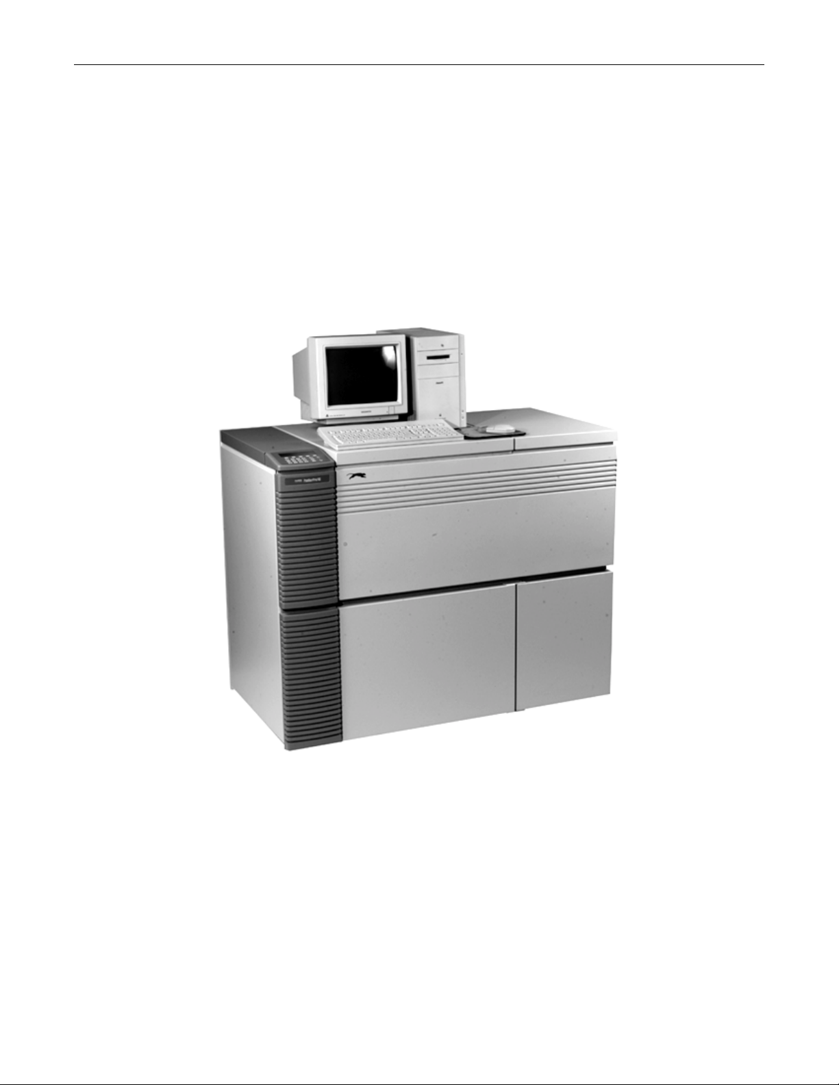
2-1 PantherPro/46 System Overview (Refer to Figure 2-1)
Supporting multiple input ports and media widths up to 18.1" (460mm), the PantherPro/46 is a
fast, commercial quality, high resolution, imagesetting system designed for high-production
applications where wide-measure imaging is required.
PantherPro/46 Imagesetting System
Figure 2-1
The Multiport™ multiplexing architecture feature allows up to four RIPs to drive a single film
recorder, and allows the addition of multiple recorders. The PantherPro/46 Image Recorder
provides a cost effective solution for environments requiring high quality, high speed,
monochromatic or color integrated text and graphics production in a wide-measure format.
The PantherPro/46 imagesetting systems feature both modular RIP and image recorder
subsystems. The RIP subsystem consists of Adobe's CPSI PostScript Level 2 RIP running on
a standard microcomputer platform. Also available as an option is the PixelBurst™ co-
October 1995 PrePRESS SOLUITIONS CONFIDENTIAL 2-1
Page 12

TP8251 PantherPro/46 Image Recorder
processor (Macitosh™ Platform), which provides significant speed improvements in RIPing
image-intensive jobs.
The PantherPro/46 image recorder subsystem is contained in a freestanding cabinet that is
supported by four casters, two of which can swivel. Adjustable gliders are located adjacent to
the casters for securing and leveling the recorder position.
The Multiport™ feature allows the recorder to be driven by up to four RIPs, each connected to
the PantherPro/46 using a SCSI (Small Computer Systems Interface) bus. The recorder can
be configured with up to four SCSI buses, each with a SCSI IN and SCSI OUT port. The
input/output ports allow you to create a daisy chain link of up to seven SCSI devices on one
SCSI bus. For example, the optional Panther Color or Plain Paper Laser printer can be
connected to the SCSI OUT port.
A standard PantherPro/46 image recorder offers ten resolution settings from 900 DPI (39.9"
per minute) to 3048 DPI (9.8" per minute) with one input port and dual 500+ MB hard disk
drives. Media widths from 12" (30.5 cm) to 18.1" (46 cm) can be loaded into the
PantherPro/46 image recorder. (The PantherPro/36 accepts media widths up to 14.1".) A
smart cassette and power-operated media cutter are also included as a standard feature.
Optionally, single input port systems can be configured with dual 1+ GB Page Buffer hard
disk drives. Up to three additional input ports can be added, each configured with either a
500+ MB or 1+ GB Page Buffer hard disk drives to accept input data from up to four Panther
RIPs. A pin registration punch system and an on-line processor interface are also available
as an option. Refer to the PantherPro/46 User's Guide for additional system configurations
and performance-enhancing options, such as:
• ESCOR II™ and ESCOR-FM™ screening
• VIM™: PrePRESS' OPI-compliant image management system
• PixelBurst™ accelerator card for faster RIPing times (Macintosh Platforms only)
2-2 PantherPro/46 Image Recorder Hardware Overview
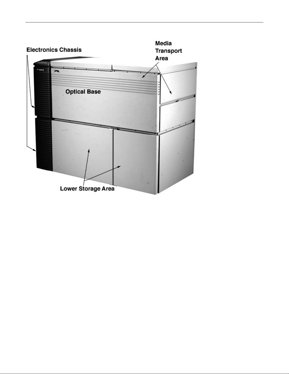
The components of the PantherPro/46 recorder are located in three separate areas of the
cabinet: electronics chassis, optical base, and media transport. The lower storage area is part
of the cabinet internal main frame that supports the major components and covers.
Refer to Figure 2-2 on the next page.
2-2 PrePRESS SOLUTIONS CONFIDENTIAL October 1995
Page 13
PanthePro/46 Image Recorder TP8251
PantherPro/46 Component Areas
Figure 2-2
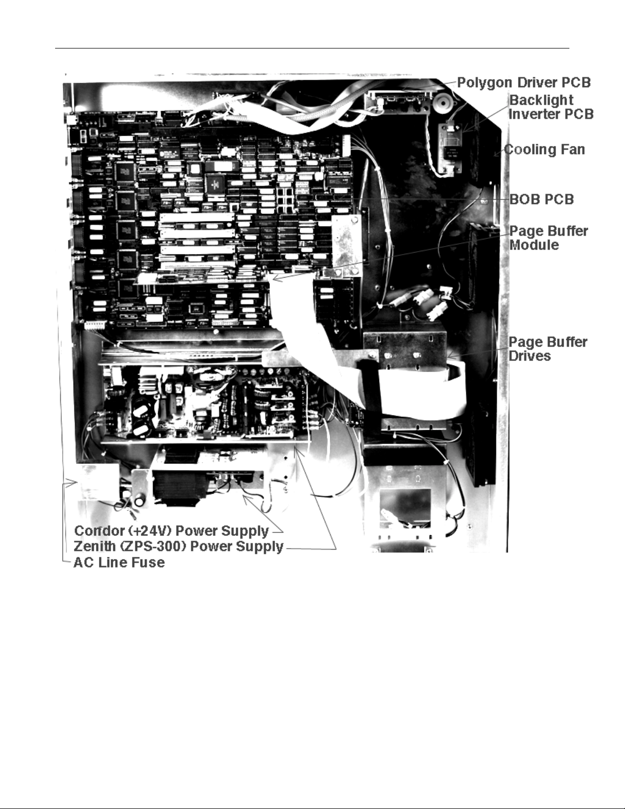
2-2.1 Electronics Chassis (Refer to Figure 2-3)
The electronics chassis is mounted on the left side of the cabinet. The major components
contained in the electronics area include:
• Controller Board (WCB/BOB) and plug-in Page Buffer Module(s)
• Polygon Driver PCB
• Page Buffer Drives
• Graphics LCD and Terminator PCB
• Zenith ZPS-300 Switching Power Supply (+5v, -12v, +12, +12v)
• Condor Polygon Power Supply (+24v)
• Back Light Inverter PCB
• AC Line Fuse (2)
• Cooling Fans (3)
Refer to Section 3 for a description of each component.
October 1995 PrePRESS SOLUITIONS CONFIDENTIAL 2-3
Page 14
TP8251 PantherPro/46 Image Recorder
PantherPro/46 Electronics Chassis Component Layout
Figure 2-3
2-4 PrePRESS SOLUTIONS CONFIDENTIAL October 1995
Page 15

PanthePro/46 Image Recorder TP8251
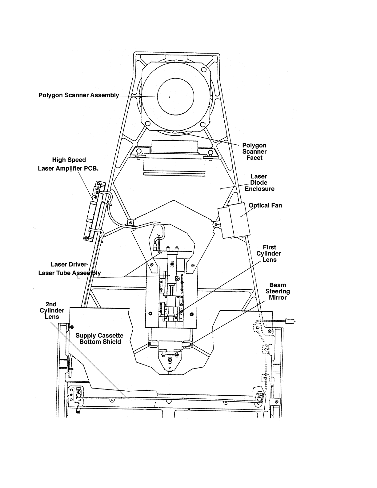
2-2.2 Recorder Optical Bed
The optical components are mounted on a rigid base casting and are under the optics cover
and supply cassette bottom shield. The major components contained in the recorder optics
bed include:
• Polygon
• Scan Lens
• High Speed Laser Amplifier Board
• Laser Driver/Laser Tube Assembly
• 1st Cylinder Lens
• Beam steering Mirror
• Second Cylinder Lens and Mask
• Start Of Line Sensor/Start Of Line Amplifier Assembly (SOL)
Refer to figure 2-4 for the recorder optical components.
October 1995 PrePRESS SOLUITIONS CONFIDENTIAL 2-5
Page 16
TP8251 PantherPro/46 Image Recorder
PantherPro/46 Optical Components
Figure 2-4
2-6 PrePRESS SOLUTIONS CONFIDENTIAL October 1995
Page 17

PanthePro/46 Image Recorder TP8251
2-2.3 Recorder Media Transport and Drive (Refer to Figure 2-5)
PantherPro/46 mechanical components such as rollers, motors, and inter-lock switches are
located in the media transport section. The media transport components are easily accessed
by lifting the supply cassette cover (and in some cases, the rear access panel). The media
drive components are accessed by removing the rear access panel. The major components
contained in the recorder media transport and drive include:
• Smart Supply Cassette
• Drag Roller and Clutch
• Gate Assembly
• Media Out Switch
• Drag-Pinch Roller
• Optional Pin Registration Punch System
• Image Roller
• Drive-Pinch Rollers
• Laser Safety Interlocks
• Worm Gearbox Assy.
• Leading Motor/Encoder
• Drive Roller
• Spur Gear
• Power Knife
• Knife Carriage Assy.
• Motor Assembly
• Lead Screw
• Stationary Knife
• Pressure Plate
• Media Guides (upper, lower)
• Knife Electronic-Opto Sensors (2)
• Manual Feed Push Button
• Cassette Out Switch
• Take-Up Cassette
• Take-Up Catch Rollers
• Take-Up Access Door Open Switch
October 1995 PrePRESS SOLUITIONS CONFIDENTIAL 2-7
Page 18

TP8251 PantherPro/46 Image Recorder
PantherPro/46 Media Transport
Figure 2-5
2-8 PrePRESS SOLUTIONS CONFIDENTIAL October 1995
Page 19

PanthePro/46 Image Recorder TP8251
2-3 Electrical Power Requirements (Refer to Figure 2-6)
Power line to be minimum 10 amp rating, with isolated 3rd wire ground. AC receptacle
should be Hubbel outlet Part Number IG5262 or equivalent.
Input Voltage/Power Line 115 VAC+/-10%, 2 amps, single phase, 50-60Hz
230 VAC+/-10%, 1 amp, single phase, 50-60Hz
Power Consumption Approximately 175 watts, AC
Heat Dissipation Approximately 600 BTU/hr.
Input Voltage Power Line
Figure 2-6
October 1995 PrePRESS SOLUITIONS CONFIDENTIAL 2-9
Page 20

TP8251 PantherPro/46 Image Recorder
2-4 PantherPro/46 Recorder Specifications
Maximum Line Length: 18.1 inch (460 mm)
Resolutions (H x V): 3048 x 3048, 1524 x 1524 (can be imaged 1524 x 3048)
2540 x 2540, 1270 x 1270 (can be imaged 1270 x 2540)
2400 x 2400, 1200 x 1200 (can be imaged 1200 x 2400)
2032 x 2032, 1016 x 1016 (can be imaged 1016 x 2032)
1800 x 1800, 900 x 900 (can be imaged 900 x 1800)
Spot Size: 15µ (.0006") @ 1800 dpi to 3048 dpi
30µ (.0012") @ 900 dpi to 1524 dpi
Absolute Accuracy: ± 0.004 inch over 18 inch
Repeatability: ± 0.001 inch typical over 8 contiguous color separations
nominal 18" in length *
Linearity: ± 0.001%, measured from center of image
Imaging Speed: 3048 x 3048 dpi: 11.6 inches/minute (249mm/min)
2540 x 2540 dpi: 13.9 inches/minute (353mm/min)
2400 x 2400 dpi: 14.7 inches/minute (373mm/min)
2032 x 2032 dpi: 17.4 inches/minute (442mm/min)
1800 x 1800 dpi: 19.7 inches/minute (500mm/min)
1524 x 1524 dpi: 23.2 inches/minute (589mm/min)
1270 x 1270 dpi: 27.9 inches/minute (709mm/min)
1200 x 1200 dpi: 29.5 inches/minute (749mm/min)
1016 x 1016 dpi: 34.8 inches/minute (884mm/min)
900 x 900 dpi: 39.3 inches/minute (998mm/min)
(Imaging speed does not include processing and RIPing
time)
Recording Method: Visible Red Laser Diode (wavelength: 670nm)
Page Buffer Disk Drive(s): The standard single input port system is equipped with dual
500+ MB Page Buffer hard disk drives.
Options:
Dual 1+ GB Page Buffer hard disk drives for increased file
stacking capability.
Up to three additional ports with 500+ or 1 + GB page buffer
hard disk drives.
Page buffer drives for input ports must match in capacity.
Multiport: Up to 3 additional input ports can be added, each
supporting either a 500+MB or 1+GB Page Buffer hard
disk drive, for a total of 4 input ports with 5 Page Buffer
hard drives to accept input from up to 4 RIPs.
2-10 PrePRESS SOLUTIONS CONFIDENTIAL October 1995
Page 21

PanthePro/46 Image Recorder TP8251
Output Media: Capable of accepting 12" (305mm), 13.3"(338mm), 14"
(356mm), 16" (406mm), and 18.1" (460mm) of visible
red-sensitive, resin-coated paper, polyester film, and direct-
to-plate material up to 0.0008" thick. Special
cassette
required for .007"/.008" media.
Supply Cassette Capacity: Up to 246' (75m) paper, film, or plate material (depending
on media type and vendor packaging configurations)
Adjustable for use with media widths: 12" (305mm),
13.3"(338mm), 14" (356mm), 16" (406mm), and 18.1"
(460mm)
Take-up Cassette Capacity: Cassette capacity: up to 50' (15.2m) for .004" thickness film
or paper (plate material capacity may vary)
A separate cassette is required for each media width: 12"
(305mm), 13.3" (338mm), 14" (356mm), 16" (406mm), and
18.1" (460mm). One cassette is included.
Optional take-up cassette for 0.007"/0.008" thick film or
direct-to-plate media (approx. 20'/6.1m capacity; varies with
media type)
A separate cassette is required for each media width.
Page Depth: Application dependent
User Controls: Paper advance; motorized media cutter; optional punch
enable; display of operator status messages
Other Options: On-line processor interface
Pin registration punch
Additional 50' (15.2m) take-up cassette
Additional 0.007"/0.008" media take-up cassette
Additional 246' (75m) supply cassette
Panther Laser Printer plain-paper image
recorder (115VAC/60Hz only)
Panther Color Printer
Pin Registration Punch
Punch Orientation: In-line, across the media width
Hole configuration: Five Standard options. Custom option also available.
Media widths: The Stoesser based options are usable with all supported
media widths (12" through 18.1") and the Bacher version
supports 14" through 18".
Media type: Film, Paper and Direct-to-Plate Polyester or Paper material
from 0.003" to 0.008" thick.
October 1995 PrePRESS SOLUITIONS CONFIDENTIAL 2-11
Page 22

TP8251 PantherPro/46 Image Recorder
Punch hole location: Holes are punched after imaging takes place, producing a
"tail punch". A "head punch" is produced by automatically
rotating the image 180° before imaging.
Vertical distance, Holes may be positioned from 1.5" inside the edge of the
hole to image: image area up to 6.0" outside the image area. Position is
software controlled and is set by the user at the operators
panel.
Hole to following 1.75" minimum. Larger spacing is software controlled and
image distance: is set by the user at the operators panel.
Punch timing: 2.3 second punch cycle plus media positioning time.
Media positioning: 2.8 seconds at 900 DPI, 9.0 second at 3048 DPI for holes
located at the edge of the image area. Time varies with
used definable spacing.
Horiz. position ±0.015"
accuracy:
Horiz. position ±0.001" (with respect to image area)
repeatability:
Vertical position accuracy: ±0.005"
(hole to image)
Vertical position ±0.001" (with respect to edge of image area;hole to image)
repeatability:
Certifications: Designed for:
UL 1950, CSA C22.2 No. 950; FCC Class A, Canadian
DOC; 21 CFR 1040.10 Class I EN60950/IEC 950; EN55022
Class A; EN50082-1; IEC 825/VDE 0837 Class 1
Interface: SCSI interface to host microcomputer
Operating Environment
Temperature: 60 to 90 degrees F (16 to 32 degrees C)
Humidity: 40% to 80% non-condensing
Heat dissipation: Approximately 600 BTU/hr
Noise emission: Less than 60db
Altitude: Sea level to 7,500 ft (2,286m)
2-12 PrePRESS SOLUTIONS CONFIDENTIAL October 1995
Page 23

PanthePro/46 Image Recorder TP8251
Ambient Light: Less than 0.05 density increase on film with ambient of 100
ft.-candles after 168 hrs. with access doors closed or 10
minutes with doors open and take-up cassette in place.
Recorder Dimensions: 53" (W) x 45" (H) x 28" (D)
(1,346.2mm x 1143mm x 711.2mm)
Recorder Weight: Approximately 454 lbs. (206kg)
* Tolerance based on eight consecutive pages using PrePRESS Solutions' large-capacity
(246'/75m) supply cassette. Actual results may vary depending on environmental conditions
and media used. Recommended environment for color separations accuracy: temperature
70° ±3° F; relative humidity: 55% ±5%.
October 1995 PrePRESS SOLUITIONS CONFIDENTIAL 2-13
Page 24

PantherPro/46 Image Recorder TP8251
Section 3 Theory of Operation
3-1 PantherPro/46 Image Recorder
3-1.1 Product Overview
The Big Output Board (BOB) and Page Buffer Module (PBM) are two electronic components
of a high resolution, capstan driven, wide-measure image recorder, called the PantherPro/46.
The primary distinguishing feature of the PantherPro/46 image recorder is its wide line
length, up to 18.1". Another distinctive feature is the Multiport™ multiplexing architecture
which allows up to four RIPs to drive a single recorder, and allows the addition of multiple
recorders. An additional Page Buffer Module and Page Buffer hard disk drive is connected to
the recorder's Big Output Board for each RIP that is connected to its SCSI input port.
3-1.2 Structure
The PantherPro/46 base casting design is predicated on the base castings used in the
Panther and PantherPro series. The size and weight of the base casting is substantially
greater to accommodate the longer optical focal plane and wide image area. In addition to
the wider image plane, many less obvious product enhancements are incorporated in the
PantherPro/46 image recorder. New features of the PantherPro/46 not contained in the
Panther and PantherPro series are as follows:
• The second cylinder lens is no longer factory aligned and set in a base plate. The
second cylinder lens rests directly on the base casting machined surface
secured against a mask and four pins.
• Unlike the gate assemblies in the Panther and PantherPro series, the gate
assembly in the PantherPro/46 may be replaced with or without a pin registration
punch system.
• The rotary knife is spring loaded, and the knife motor is secured directly to the
casting, thus eliminating knife carriage lead screw and motor height adjustments.
• A rear access panel is added to facilitate part replacement. The servo gearbox
assembly, spur gear, and clutch are now easily replaced.
• The external tensioner module (ETM) is replaced with a drag roller, pinch roller,
an d adjustable clutch. This new design minimizes maintenance and improves
reliability.
• The electronics chassis is mounted to the main frame of the recorder. Most of the
recorder electronic components are mounted inside the electronics chassis and
are easily accessed once the cover is removed.
Refer to Section 2 for the location of the major components contained in the PantherPro/46
image recorder.
October 1995 PrePRESS SOLUTIONS CONFIDENTIAL
3-1
Page 25

TP8251 PantherPro/46 Image Recorder
3-1.3 PantherPro/46 Image Recorder Functional Overview
The PantherPro/46 image recorder, upon input of raster data from the RIP to the Big Output
Board, generates typographic characters and graphic images onto visible red sensitive
paper, film, or plate material. The imagesetting system, comprised of the Panther RIP and the
PantherPro/46 Image Recorder, follows this sequence to produce jobs:
1. The Panther RIP converts PostScript commands into bands of raster image (horizontal
lines of laser pixels) data, a process called RIPing. The recorder's BOB, SCSI MUX Module,
receives the raster data from the RIP (host) via the SCSI bus when the recorder "Main
Application" program is loaded and the recorder is in "On-line Mode". As the SCSI MUX
Module receives the raster data during the recorder's "On-line Mode", the BOB, CPU and
Peripherals Module updates the LCD by displaying a graphic "icon" which represents the
recorder status. (Refer to the PantherPro/46 User's Guide for recorder control panel modes
and features.)
The SCSI MUX Module and the CPU and Peripherals Module are submodules of the BOB
(Big Output Board).
2. The PantherPro/46 Image Recorder Page Buffer Module will receive the SCSI raster data
from the SCSI MUX Module, compress it, and store (write) it on the recorder's page buffer
drive #1. This process is called page buffering.
The Page Buffer Module is a sub-module of
the BOB that will provide interfaces to the SCSI MUX Module, the SCSI Page Buffer hard
disk drive, the Recorder OutPut Module (ROPM),
and to theCPU/Peripherals Module.
3. When the page buffering process is complete, Page Buffer drive #1 will become the
imaging drive. The Page Buffer Module will be instructed to read the stored (compressed)
data from imaging drive #1, decompress it, and send the raster data to the ROPM for imaging.
The ROPM is a submodule of the BOB. The ROPM contains the circuitry
related to the recorder functions. This can divided into two basic areas: Video Channel,
and Motor Control.
4. The ROPM will receive the decompressed video data and pass it on to the Video Channel.
The ROPM Video Channel will send video data (signals) to the High Speed Laser Amplifier
PCB.
5. The video signals received from the Video Channel are amplified and regulated by the
High Speed Laser Amplifier PCB and sent to the High Speed Laser Driver PCB/Laser Diode
Assembly.
6. The Laser Driver PCB /Laser Diode Assembly generates the visible red laser beam which
is dispersed across the SOL/SOL Amplifier and image focal plane (media) by a polygon
scanner motor and optical system. The media is moved vertically across the imaging plane
by a servo leading motor, which is controlled by the ROPM Motor Control circuits.
7. While Page Buffer drive #1 is imaging (steps 3, 4 and 5), the Panther RIP buffers the next
page on Page Buffer drive #2. (Refer to the PantherPro/46 User's Guide for RIP information
about contiguous pages and page stacking modes.)
8. When Page Buffer drive # 2 is finished buffering, Page Buffer #2 becomes the imaging
3-2 PrePRESS SOLUTIONS CONFIDENTIAL
October 1995
Page 26

PantherPro/46 Image Recorder TP8251
drive, and sends data to the recorder while Page Buffer #1 receives the next page.
Alternating between pages stored on page buffers allows the Panther Pro/46 to operate in a
smooth, continuous motion, without needing to wait for the RIP to process the next page.
This process continues as the PantherPro/46 outputs jobs; the Panther RIP alternates
between disks to buffer jobs. One disk buffer can output a page to the recorder while the
other disk is buffering.
When multiple Panther RIPs are connected to the PantherPro/46 image recorder, all page
buffer disks can be active at the same time. While one page buffer is outputting data to the
recorder (imaging), other page buffer disks can be buffering.
3-2 Big Output Board (BOB)
3-2.1 Functional Overview
The Big Output Board (BOB) is an updated version of the WCB (Wide Controller Board). The
BOB includes all the features of a WCB, plus some minor new features.
Note: The BOB can replace a WCB or HSCB in any (PantherPro/46 or PantherPro) recorder;
however, because of hardware differences, such as polygon speed and image line length, a
software update and PAL changes are required.
New features of the BOB that are not contained on the WCB are as follows:
• Colenta on-line processor interface
• Larger field rams (Hitachi HM53281)
• Relay added to cutter circuit
• New Board Type Register bit and second register
Common features incorporated in the BOB and WCB are as follows:
• Punch control and drive circuits
• Leading Encoder register for leading position feedback
• Circuitry supporting optical interrupter switches for cutter position
• Support for manual leading switch
• Board type register
• Support for 18.1" images at the following rates:
11.6 IPM @ 3048 DPI
14.4 IPM @ 2540 DPI
14.8 IPM @ 2400 DPI
17.5 IPM @ 2032 DPI
19.7 IPM @ 1800 DPI
• Supply Cassette configuration memory (for Smart Supply Cassette)
• On-line Processor Interface (PrePRESS OEM Specification/Non-Colenta)
• Power film cutter
• Up to four independent SCSI inputs
October 1995 PrePRESS SOLUTIONS CONFIDENTIAL
3-3
Page 27

TP8251 PantherPro/46 Image Recorder
• One to five Page Buffer disks for simultaneous buffering
• 11 Programmable resolutions (3600 DPI not used in recorder main program)
• Programmable leading speed
• LCD/Keypad user interface
• Programmable LCD contrast
• Debug port/remote diagnostics
• Programmable Beep Volume
The BOB is the main electronics assembly in the PantherPro/46. It consists of 4 distinct
submodules:
• SCSI MUX Module
• CPU and Peripherals Module
• Page Buffer Module
• Recorder OutPut Module
Refer to the BOB/WCB Block Diagram below.
Up to four Page Buffer Modules (plug-in daughter cards) may be added to the BOB, in
addition to the Page Buffer Module which is always resident. The PantherPro/46 standard
configuration is equipped with two Page Buffer Modules: the BOB resident Page Buffer
Module and one plug-in Page Buffer Module.
3-2.2 Description
3-2.2.1 SCSI Multiplexer (MUX) Module
The SCSI MUX Module is a submodule of the BOB that contains the logic needed to interface
any combination of four RIPs and five Page Buffer Modules.
The SCSI MUX is implemented as five four to one input ports. Each port is designed in a
modular fashion. This will allow a reduced cost for an entry level system. It will also allow
MUX channels to be added or deleted as the system configuration requires. The SCSI Mux
contains four functional sections; input buffers, muxes, control logic, and test paths.
A. SCSI MUX Buffers
The SCSI Mux Buffers contain the interface to the connecting RIPS. The buffers for each
channel (SCSI In/SCSI Out) support SCSI - 2 Single Ended Alternative.
The connector used is a dual SCSI-2 connector, wired in common so that the SCSI port does
not need to be the last device on the SCSI bus. The left connector of each pair is labeled
"SCSI In" and is connected to the front end (host). The right connector is labeled "SCSI Out"
and is used to daisy chain other devices on the SCSI bus only when the "SCSI In" connector
is already used. SCSI In 0 port is always the first port connected to the RIP.
The method of SCSI bus termination is achieved through active terminators (on a per port
basis) which will be automatically disabled when a SCSI cable is sensed on the "SCSI Out"
connector.
In accordance with SCSI target mode operation, the signals C/D, I/O, MSG, and REQ will be
3-4 PrePRESS SOLUTIONS CONFIDENTIAL
October 1995
Page 28

PantherPro/46 Image Recorder TP8251
received by the RIP. The signals RST, ACK, and ATN will be received by the MUX. The
Signal DB[0..7], DBP, BSY, and select will be driven bidirectionally between the RIP and
MUX.
B. SCSI MUX Control Logic
There are four registers used by the control logic; an ID register, a select register, a revision
register, and an arbitrate register. Only the select register is read/write. All registers are 16
bits wide. Bits not used are not driven. Byte access is not supported.
C. SCSI MUX MUXES
The MUXES are implemented using 160 pin gate arrays. The arrays incorporate all of the
muxes for five channels/Page Buffer Modules (including the built in) and the control logic
needed to select the direction of the SCSI data bus, and the signals BSY~ and SEL~.
D. SCSI MUX Test Path
Testing of the SCSI Mux channels are done by connecting a cable (loopback) from the SCSI
Loop Back connector to the port to be tested.
3-2.2.2 CPU and Peripherals Module
The CPU and Peripherals Module provides processing power, program and data storage,
and I/O needed to support the PantherPro/46 image recorder. The CPU and Peripherals
Module consists of thirteen sections which are described below.
A. Microprocessor
A Motorola 68000 running at 16.67 MHz is utilized to provide processing power for the
BOB/WCB. Code is executed out of program storage. Upon request it will relinquish the bus
to other bus masters.
B. Program Storage
An EPROM is provided for program storage. This is a 'by 16' part. The EPROM resides at
location 0 and at location 0x200000 at power-up. Once the program code starts executing out
of the 0x200000 space, the EPROM will no longer reside at location 0.
C. DATA Storage
A DRAM storage system will be provided for CPU data storage. This provides 2 MB of
memory. The DRAM is enabled at location after the EPROM starts executing code out of its
upper space.
The DRAM consists of four 1MB x 4 parts. A DRAM controller generates read, write, and
refresh cycles to the DRAM. The design supports use of 4 256K x 4 parts, providing 512K of
memory.
D. Non-volatile RAM
A 2k byte NV RAM is provided. It resides on the upper 8 bits of the 68000 data bus. Its base
address is 0xD00000.
E. Interrupt Controller
The interrupt controller receives interrupts from each page buffer module and other
peripherals in the system. Page buffer modules are capable of generating 3 interrupts; one
October 1995 PrePRESS SOLUTIONS CONFIDENTIAL
3-5
Page 29

TP8251 PantherPro/46 Image Recorder
from the HOST_SIOP, one from the Disk_SIOP, and one from the (AHA) 3210
Compressor/Decompressor chip. The Disk_SIOP and the 3210 (Page Buffer Module) that is
imaging is given priority level 5. A mask register is loaded indicating which page buffer is
imaging. All other Page buffer interrupts share interrupt level 4. Interrupt vectors are provided
for each interrupt level.
The other system peripheral interrupts include:
• ROPM (end of scan (EOS), video pipe full, and leading encoder register)
• Duart/Timer
• LCD Timer
• Keypad/On line Processor (OLP)
The EOS will generate a level 6 interrupt (highest level). This interrupt line is shared by the
"full" interrupt from the ROPM, and by a leading encoder register interrupt from the ROPM.
The DUART/Timer will generate a level 3 interrupt. The LCD Timer will generate a level 2
interrupt. The level 1 interrupt will be shared between the keypad and the Colenta on-line
processor interface.
F. DUART/Timer
A 2681 DUART/Timer will be used. This will provide 2 serial channels. They are configured
as DCE.
The timer is programmable. Interrupts are generated when certain DUART conditions are met
or when the timer expires. The DUART resides at address D10020 through D1003F.
G. Keypad Interface
An interface to the membrane keypad is provided. This interlace provides a means to reset
the hardware by monitoring a sequence of keystrokes. In off-line mode, depress the "." key
followed by the "arrow down" key will reset the hardware. The keypad address resides at
location D10042.
H. Address Decode
Necessary address decodes are generated for Page Buffer Modules, SCSI MUX Module,
and Recorder Output Module (ROPM).
I. Strobe/Dtack Logic
I/O strobes, read and write strobes will be generated for I/O devices. Dtack is generated for
I/O devices, memory, and registers.
J. LCD Interface
An interface to the graphics LCD is provided. An additional timer is provided to generate 100
µsec interrupts to update the LCD. The LCD resides at address D10044 through D10046.
K. Diagnostic LED Bank
A software programmable diagnostic LED bank is provided. This consists of 8 LED's. They
are enabled upon power-up.
L. Dead Man Timer
3-6 PrePRESS SOLUTIONS CONFIDENTIAL
October 1995
Page 30

PantherPro/46 Image Recorder TP8251
A dead man timer circuit is provided. If not reset every 2 seconds, a hardware reset will occur.
M. Clock Circuitry
Clocks are generated for the CPU, the Page Buffer Modules, and the DUART/Timer. A slow
clock is generated for the dead man timer.
3-2.2.3 Page Buffer Module
The Page Buffer Module is a submodule of the BOB that provides interfaces to the SCSI MUX
Module, a page buffer hard disk drive, the Recorder OutPut Module, and to the
CPU/Peripherals Module. The Page Buffer Module receives SCSI data from the host,
compresses it, and stores the compressed job/page on disk. Once a complete job/page is
compressed, and written to disk, the PBM will be instructed to decompress the stored
job/page and send the data to the Recorder Output Module on the BOB for imaging. The BOB
always has at least one PBM, which is built-in, and is all that is required to have a minimum
functional recorder. (The standard recorder comes equipped with an addition Page Buffer
Module that is received as a plug-in daughter card.)
Each PBM consists of two NCR 53c7000 SCSI input/output processors (SIOPs), one
AHA3210 Compression Coprocessor, 512kb of DRAM, a disk drive and the circuitry to control
the data movement among them. These SIOPs are referred to as the Host SIOP (interfaces to
the Mux) and the Disk SIOP(interfaces to the page buffer drive).
A. Clock Generator
The main clock is derived from a crystal oscillator (33.34 MHz) that is at twice the frequency
that the MC68000 will operate. This clock is divided in half and synchronized to the crystal
oscillator with reset. The 16.67 MHz rate is then used to run the 68000, the AHA3210's, and
as a reference for the SIOP control logic. While the SIOPs are clocked at the faster 33.34
MHz rate, internally the run at 16.67 MHz. The control logic must be aware of both rates to
properly sequence the slave cycles between the 68000 and the SIOPs.
B. 68000 Bus Arbitration Logic
Each PBM has two SIOPs, which can be bus masters. For a fully configured BOB/WCB (5
PBMs present) there are a maximum of ten devices that may request to become a 68000 bus
master. Since only a single device can own the bus at any one time, bus arbitration logic
must be implemented to control which requesting device is driving the 68000 bus. The
priority is always given to the PBM that is imaging. Any request from any input PBM is granted
only if there are none pending from the output PBM. The priorities are as follows:
1. Output PBM
2. Output PBM host SIOP
3. Input PBM disk drive SIOP
4. Input PBM host SIOP
If no output PBM requests are made, the input PBMs are granted the bus in a rotating order.
The PBM LEDs or the serial debug port will indicate which PBM is active.
C. NCR 53C700 SIOP
The NCR53C700-66 is a high speed SCSI controller with a built-in SCSI SCRIPTS
processor to perform SCSI SCRIPTS operations with minimal intervention from the BOB's
October 1995 PrePRESS SOLUTIONS CONFIDENTIAL
3-7
Page 31

TP8251 PantherPro/46 Image Recorder
68000. The SIOP must be operated in 80286 mode (16 bits) to accommodate the 68000.
Since the 53C700 is an Intel compatible device (Little Endian), byte swapping occurs in the
hardware for any access between the 68000 and the SIOP. The data rates supported by this
device are 5.0 MB/Sec in asynchronous mode and 10.0 MB/Sec in Synchronous mode. This
chip contains a SCSI controller, a 32 byte FIFO, a high performance DMA controller and a
2MIP "SCRIPTS" processor that manages the data transfers to and from the BOB local
memory.
There are two independent SCSI channels as part of this submodule. The first SCSI channel
will provide an interface to the host system via the SCSI MUX Module. This SIOP is setup to
DMA the input data from the host SCSI bus to port A of the 3210. The 3210 Port A is
configured for slave mode and will compress data as the SIOP writes to port A of the 3210.
The SIOP interrupt signals as the predetermined block size of data has been sent to the
compressor port from the host.
The second SCSI channel provides an interface to the page buffer disk. The page buffer disk
stores compressed data from port B of the 3210. During compression, this second SIOP will
read blocks of data from a local DRAM buffer and write it back to the drive. Later, the whole
compressed job is read back, decompressed, and imaged.
D. AHA 3210 Compression Coprocessor
The 3210 is used to compress the data received from the host SIOP for storage on the disk or
to decompress the stored job for output to the Recorder OutPut Module.
Initially, the host SIOP is set up in 80286 mode. The SIOP fetches instructions from the 68000
memory by becoming a bus master of the 68000. The 3210 is set up for compression with
port A as a slave and port B as a master.
3-2.2.4 Recorder Output Module (ROPM) Description
The ROPM contains the circuitry related to the recorder functions. This can divided into two
basic sections: Video Channel, and Motor Control.
The Video Channel refers to the path which video data takes from the Page Buffer Modules
until it passed it a serial stream to the High Speed Laser Amplifier PCB. This path contains a
Field Ram configured as large FIFO, a SCAN Line FIFO, a shift register, and Video Control
logic. Also included is the Margin, Xcount, Intensity, Blanking, Test Pattern circuitry, and
PCLK synchronizer and facet timer.
Motor Control refers to the circuitry which controls the Leading Motor, the Polygon, Cutter
Motor, and Punch Motor. Also included are such miscellaneous functions as media, door,
and cassette switches, supply cassette memory, -5 volt regulator, and on-line processor
interface (Colenta and PrePRESS OEM).
Video Channel
A. Dual Port Video Memory
A new feature incorporated on the BOB, and not contained on the WCB, is the larger Dual
Port Video Memory. Capacity is increased from 256k x 16 to 324k x 16. Dual Port Video
Memory operates as a large FIFO buffer. This memory shall consist of HM53281 Frame
Memories. It is loaded with uncompressed data from a page buffer module, and is output to
3-8 PrePRESS SOLUTIONS CONFIDENTIAL
October 1995
Page 32

PantherPro/46 Image Recorder TP8251
the Scan Line FIFO.
The Dual Port Video Memory must be reset before each image.
B. Scan Line FIFO
The Scan Line FIFO is 16 bits wide. It provides a full scan line of buffering at the highest
resolution. Writes into the FIFO occur as a two-clock (minimum) cycle at the system clock rate.
This will allow the FIFO logic to generate a "Full" signal which can stifle subsequent writes.
Data from the Video FIFO is read one byte at a time, as needed to load the video shift
register.
The FIFO "Retransmit" signal is used to repeat scan lines during Quality Mode. This requires
the hardware to reset the FIFO before each scan line. Upon reset, the Dual Port Video
Memory (DPVM) transfers one full scan line into the Scan Line FIFO, and then outputs the
scan line in real time to the video shift register. If the scan line is to be repeated, the scan line
is retransmitted from the Scan Line FIFO. The process is repeated for the next scan line.
C. Xcount
An Xcount register and counter contains the number of words per scan line, counting the
words transferred into the Scan Line FIFO. When the full number of words is reached,
transfers stop with the Scan Line FIFO holding a complete scan line. The Xcount register
requires loading once per image.
D. Margin and Blanking
A programmable margin is provided by the Margin Register. For each scan line, a margin
counter is loaded with the margin register contents and counted down to zero. The video is
blanked, and reading from the FIFO is inhibited until the this margin is exhausted. Once
reading from the FIFO commences, the real video is output till the right edge of the media is
reached, and the video is again held blank.
E. Fill
A fill feature allows blank scan lines to be output without fetching of video data. This allows
images to be transmitted to the PantherPro/46 without the corresponding "blank" data. The fill
feature supports automatic blanking at a granularity of single scan lines.
F. Video Control
Circuitry will count pixels, load the shift register, and issue reads to the Scan Line FIFO at
appropriate times. This circuitry is collectively known as video control.
G. Test Pattern
Capability to substitute a hardware generated test pattern for normal video is provided. Each
square of the test pattern measures 128 pixels square.
H. Serialization
Video output to the laser amplifier is a serial stream. Bytes of video from the Scan Line FIFO
is serialized in a shift register and then turned into a stream of pulses before being output to
the High Speed Laser Amplifier PCB.
October 1995 PrePRESS SOLUTIONS CONFIDENTIAL
3-9
Page 33

TP8251 PantherPro/46 Image Recorder
I. PCLK Synchronizer
A clock phase which best matches the START pulse selects each scan line and outputs a
new PCLK. This will minimize left edge jitter, keeping it to within a fraction of a pixel.
J. Intensity Control
A register which drives a D/A converter will set the laser intensity. This is the identical circuit
used on the RCB.
K. Facet Timer
A Facet Timer circuit times the scan line and issues various control signals whose timing is
related to the scan line. Examples of such signals are: Sample/Hold, Enhance, Inhibit Bias,
Speed Hi/Lo/Ok, End of Scan, etc. The decoding of these signals is fixed, and is oriented to a
specific expected polygon rotational rate. The polygon spins at 4444 rotations per minute
(RPM). One facet decoder GAL is used in BOB.
L. End of Scan interrupt
A maskable interrupt is generated once per scan during the inactive portion of a scan line.
Motor Control
M. Polygon Speed control
Polygon Speed Control consists of a 16 bit register and a 16 bit counter. On overflow, the
counter is loaded from the register, creating a programmable time base.
The output of this circuit is the square wave POLYCLK, which is fed to the polygon drive
circuitry and resides on the Polygon Driver PCB.
N. Leading Motor Control and Drive
The Leading Motor Control consists of a paper feed register, an adder/accumulator, and a
Galil GL1200 motor control IC. The adder/accumulator produces a series of pulses at a rate
set by the Paper Feed register. The GL1200 converts this into position information,
comparing with encoder inputs. Also, the GL1200 outputs velocity information. The position
and velocity information are summed with the accelerator information to form the input to the
motor drive. A nearly identical circuit is used on the RCB, HSCB, and WCB.
A leading encoder counter circuit makes a running count of encoder pulses available to
software to provide leading position feedback, which may be used to facilitate punch
positioning. This register can also be enabled to interrupt after the occurrence of a specified
number of encoder pulses.
The analog circuitry which drives the leading motor is virtually identical to the circuit used on
the RCB, HSCB, and WCB.
O. Cutter Motor Control and Drive
The cutter motor is implemented by 5 bits of the Motor Control Register. Cutter power is
programmable in 10% steps from 70% to 100%. The cutter motor is driven as on the RCB.
The cutter motor is removed from the circuit on power down by a relay. This prevents the
cutter motor from acting as a generator when manually operated after powered down. This is
transparent to software.
3-10 PrePRESS SOLUTIONS CONFIDENTIAL
October 1995
Page 34

PantherPro/46 Image Recorder TP8251
P. Punch Motor Control and Drive
The punch motor control is implemented by 1 bit of the Motor Control Register. The punch
runs for a minimum of 1.5 seconds, and stops when the Punch Home switch is closed.
Software will be able to determine through 2 status bits when a punch cycle has completed
and whether the punch is at "home position", out of the film path. A circuit detects the
presence of a punch motor, and informs software by a register bit.
Q. On-line Processor (OLP) Interface
A register is provided whose bits control and monitor a pair of On-line Processor interfaces. A
Colenta OLP interface is added to the high byte of the register, while the existing LOG-E
interface (PrePRESS OEM) remains unchanged in the low byte.
The BOB has a 26 pin header, which connects to the I/O bulkhead via a 26 pin ribbon cable
to a 25 pin D connector.
3-3 High Speed Laser Amplifier (HSLA) PCB
3-3.1 Functional Overview
The High Speed Laser Amplifier (HSLA) PCB interfaces to the Big Output Board and High
Speed Laser Driver (HSLD) PCB. The start of line (SOL) sensor is also connected to J1 of
the HSLA PCB.
New features included in the HSLA PCB are as follows:
• Increased data throughput to allow for the higher data rates required.
• The video pulse forming circuitry has been moved to the WCB/BOB where
it shall be formed using the pixel clock. This allows for an average laser
power of 50% to be more closely achieved, regardless of the recorder
resolution.
• The functions of the HSLA PCB and HSLD PCB have been rearranged to
allow for independent replacement. They are no longer a matched set .
• Laser ENHANCE time power, the laser mode before start of each scanline,
is no longer related to the laser's intensity during imaging. For example,
the exposure settings shall not influence the ability of the HSLA PCB/SOL
sensor to detect a "START" pulse.
The HSLA PCB contains the following circuitry:
• Buffering circuitry for all signals passed to the High Speed Laser Driver
(HSLD) PCB.
• Sample Hold Circuit which samples laser power for calibration.
• Voltage Regulation
• Start of Line Detection
3-3.2 Description
3-3.2.1 Signal Buffering
The Video (Intensity, Sample/Hold, Video, Bias_On, Start) and ENHANCE signals are simply
buffered on the HSLA PCB and passed on to the HSLD PCB. It is the duty of the BOB/WCB to
October 1995 PrePRESS SOLUTIONS CONFIDENTIAL
3-11
Page 35

TP8251 PantherPro/46 Image Recorder
do the appropriate pulse forming.
3-2.2.2 Laser Power Regulation
The HSLA PCB has an on-board voltage regulator to turn +12 volts into +7.5 volts which is
then passed on to the HSLA PCB for use in its variable current source. Refer to
Reference/Adjustments Section for 7.5 volt calibration procedure.
3-3.2.3 Start Of Line Detection
The start of line (SOL) circuitry is used to detect the laser beam output before the start of
each scanline. Although the actual SOL (split) sensor is mounted in the front of the base
casting, on the left edge of the imaging plane, the support electronics are located on the
HSLA PCB.
The HSLA PCB supplies the SOL (split) sensor with power and monitors its left and right
sensor outputs with a high speed ECL (emitter coupled logic) comparator to determine when
the laser beam has crossed the 5 micro gap. The signal then goes through the ECL
comparator and ECL driver circuit on the HSLA PCB which sends the start signals
(Start,Start/) to the BOB's ROPM.
The most critical aspect of the SOL sensor is its left to right position. For example, the laser
ENHANCE time power (beam) must fully sweep across the SOL left and right (split) sensor
for stable operation.
3-4 High Speed Laser Driver PCB/Laser Tube Assembly
3-4.1 Functional Overview
The High Speed Laser Driver (HSLD) PCB interfaces to the High Speed Laser Amplifier
(HSLA) PCB and Laser Diode.
The HSLD PCB contains the following circuitry:
• Variable current source
• Current limiter
• Enhance circuitry with power adjustments
• Feedback of laser power
• Calibration adjustments to calibrate laser
3-4.2 Description
3-4.2.1 Variable Current Source with current limiter
The HSLD PCB has two transistors hooked up as current sources using the CONTROL line
as their base voltage. One current source is for BIAS current and the other is for VIDEO
current. For current limiting, the CONTROL signal is kept within a safe range by use of a
zener clamp.
3-4.2.2 Current Steering
The laser is switched to OFF by using an ECL gate to draw the current away from the laser or
ON by allowing the current to flow through the laser diode. These two gates (one for each
current source) are controlled by VIDEO and BIAS.
3-12 PrePRESS SOLUTIONS CONFIDENTIAL
October 1995
Page 36

PantherPro/46 Image Recorder TP8251
3-4.2.3 Power Detection Calibration
The laser diode has a built in photodiode which is used to determine the laser output power.
Using this sense line from the laser, a proportional current is generated and sent to the HSLA
PCB for use in its feedback loop for power adjustment. This is the area where potentiometer
adjustments for the laser power calibration are made to alter the relationship between the
sense line and PD (photo diode). The BOB/WCB SW4 switch positions are altered during the
Laser System Calibration tests to adjust for the laser's ENHANCE time power, Efficiency
Power, and Threshold Power. Refer to Section 8 for the "Laser Power Calibration" procedure.
3-5 Graphics LCD/Keypad Assembly and Back Light Inverter PCB
3-5.1 Functional Overview
The Graphics LCD and Keypad Assembly contains a LCD with a plug-in Terminator PCB and
a separate membrane keypad. The keypad is attached to the front bezel.
The Back Light Inverter PCB is located in the electronics chassis in the below the LCD.
3-5.2 Description
The Graphics LCD contrast is adjustable for easy viewing in a wide range of lighting
conditions. Refer to the PantherPro/46 User's Guide for details on how to adjust the Graphics
LCD contrast.
The Backlight Inverter PCB converts DC (+5) voltage to approximately 240 VAC.
3-6 Media Transport Section
(Refer to Figure 3-1 Media Feed Diagram)
3-6.1 Functional Overview
The media transport assembly is used to accurately feed visible red sensitive media from the
supply cassette through the image plane and optional pin registration punch system, and into
the take-up cassette. The media feed mechanism is a capstan drive roller which is driven by
a servo motor under logic control. The media transport is capable of feeding 12", 13.3",
14",15", 16", and 18.1" media.
The major components contained in the recorder media transport include:
Smart Supply Cassette
Drag Roller and Clutch
Gate Assembly
image rollers)
(media out switch, drag-pinch roller, optional pin registration punch system, drive-pinch roller,
Drive Roller
Worm Gear Box (leading motor/encoder)
Spur Gear
Manual Feed Push Button
Knife Carriage and Motor
Take-Up Catch Roller
Take-Up Cassette
October 1995 PrePRESS SOLUTIONS CONFIDENTIAL
3-13
Page 37
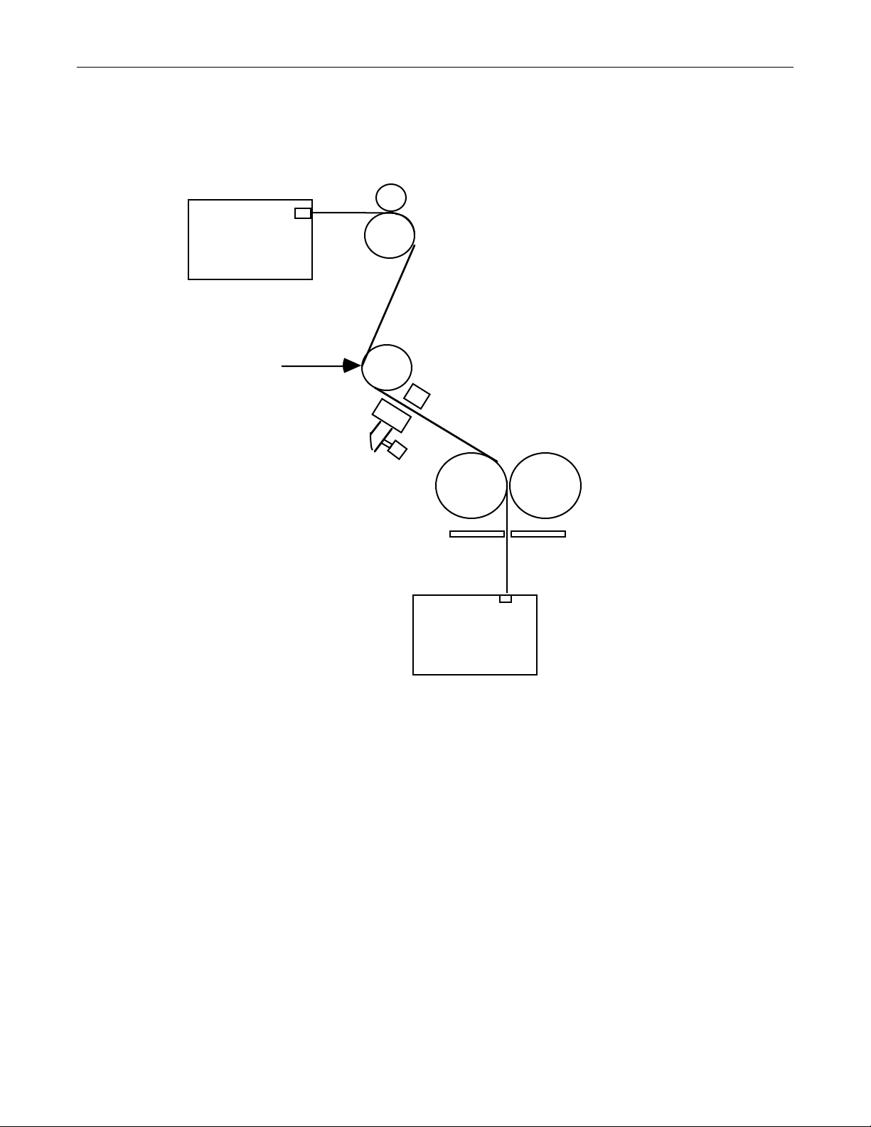
TP8251 PantherPro/46 Image Recorder
Drag - Pinch Roller
Supply
Cassette
Laser Beam
Drag Roller
Image Roller
Optional Punch System
Drive - Pinch
Rollers (2)
Drive Roller
Take-up
Cassette
Media Feed Diagram
Figure 3-1
The smart supply cassette is a rectangular plastic box consisting of a top and bottom cover,
held together by four polypropylene clasps. A memory button, that is used to store the
cassette media information, is mounted to the outside of the bottom cover. Inside the cassette,
is a shaft and two adjustable hubs with 2" media core spindles. (Refer to PantherPro/46
User's Guide, for "Loading the Supply Cassette".)
The media exists the supply cassette horizontally between the drag roller and pinch roller. As
the media moves past the drag roller, pinch roller, and media out switch, the media changes
from a horizontal to a vertical position. The backside (emulsion in) of the media is then drawn
across the imaging roller exposure plane.
Once past the imaging roller, the media will be drawn through an "optional" pin registration
punch system by the drive roller and idler rollers.
3-14 PrePRESS SOLUTIONS CONFIDENTIAL
October 1995
Page 38

PantherPro/46 Image Recorder TP8251
The drive roller and pinch rollers will push the media through the upper media guides, across
the anti-static brush, and past the stationary knife into the take-up cassette. The knife can also
be operated manually.
3-6.2 Description
3-6.2.1. Smart Cassette
The smart cassette rests on the base casting above the supply cassette bottom shield. The
1K touch memory button data is transferred serially through the transmit/receive and ground
contacts which are mounted on, but isolated from, the surface of the supply cassette bottom
shield.
Inside the cassette, a thumbscrew is installed in one of the shaft "media holes" to set the left
hub position. The media is centered on the shaft in the supply cassette between the left and
right hubs.
A ball plunger screw installed in the right side of the bottom cover, adjacent to the shaft, is
used to push the shaft against the left set screw. The left set screw is used to keep the shaft
from digging into the bottom cover sides.
Anti-slip tape and hold down clip is fastened to the bottom cover shaft pedestals to provide
back tension.
A copper grounding spring, mounted on the right side of the casting, is used to discharge
static electricity from the bottom cover rivet.
3-6.2.2 Pinch Roller
The pinch roller, which rests on top of the media and drag roller, is used as a weight to keep
the media from slipping across the drag roller. The pinch roller is part of the gate assembly.
3-6.2.3 Drag Roller and Clutch
The clutch is secured to the drag roller shaft by two set screws and mounted to the casting by
three protruding dowel pins. The clutch produces a drag roller tension near 40 ounces (when
measured with a strain gauge and string). The drag roller and clutch regulate accuracy and
skewing.
3-6.2.4 Image Roller
The image roller positions the media in the laser beam focal plane. The circumference of the
image roller is 3.927 inches.
3-6.2.5 Drive Roller
The drive roller is rotated by the spur gear, which is attached to the leading motor gear box.
One drive roller rotation equals 4.712 inches.
3-6.2.6 (Drive) Pinch Rollers
Two pinch rollers push the media against the drive roller. The gate pinch roller to drive roller
pressure is factory set to 0.125". (The shoulder screws located on each end of shaft are used
to position the idler rollers. Two set screws, located behind the gate frame adjacent to the
shaft shoulder screws, lock the shaft in place.)
October 1995 PrePRESS SOLUTIONS CONFIDENTIAL
3-15
Page 39

TP8251 PantherPro/46 Image Recorder
As the gate is closed, both pinch rollers shall contact the drive roller 0.125" before the gate
frame rests against the gate frame stop pins.
3-6.2.7 Pin Registration Punch System
The punch system is capable of punching two to four holes in a single line across the width of
the media. Either head or tail punching is supported (but not on the same page). Punching
takes place after the image is recorded. To achieve a head punch, the image must be rotated
180°.
The punch system main components include a front and rear casting, cam bar, stripper plate,
round and/or oval punch pins, a punch motor, roller crank, punch home switch, and yoke.
During a punch cycle, holes are punched after imaging takes place. The punch hole location
is determined by software. Media positioning speed varies with resolution and distance from
image to punch holes. When +12 volts DC is applied to the punch motor, the roller crank,
which is secured to the motor shaft flat with a set screw, will rotate and lift the yoke. The yoke,
which is secured to the cam bar shaft flat, with a set screw, acts like a lever and pivots the
cam bar to extend its mounted punch pins through the media. The punch stripper plate will
apply pressure to the media as the punch motor rotates and pivots the cam bar and punch
pins. When the punch pins are near full extension the media will be punched. The film chaff
will pass through the rear casting and fall into the chaff tray which is attached to the rear
casting with two thumbscrews. As the motor completes one revolution, the switch plate
(attached to the cam bar) will return to its original position and defeat the home switch.
Software recognizes when the punch home switch is closed, and stops the motor.
3-6.2.8 Worm Gear Box Assembly and Spur Gear
The worm gear box assembly contains a servo leading motor/encoder, gear box, and
hardened worm gear.
The "Leading Motor Control" provides closed loop position and velocity control of the servo.
Control signals are amplified to form the input to the leading motor analog drive circuitry.
Leading motor encoder pulses (ENCDRA and ENCDRB) are monitored by the GL1200 IC to
form position information necessary for accurate registration. The media may be moved at
different speeds to accommodate different resolution of the images being output as well as
the high speed preset or manual advance function.
Attached to the leading motor shaft is a worm that meshed with a spur gear attached
(clamped) to the drive roller, which creates a 144 to 1 reduction ratio.
3-6.2.9 Power Knife
The power knife is a spring loaded, rotary knife assembled in a carriage which transverses
across a stationary knife, located behind the media path. A Teflon™ coated worm gear,
secured to the 'flat' of the knife motor shaft, is the mechanism that provides bi-directional
movement for the knife carriage assembly.
Rotation of the knife is provided by an O ring which is mounted axially on the same shaft. The
O ring is rotated due to frictional contact with the spring loaded pressure plate. The bar is
spring-loaded outwards to permit passage of the media. It is compressed downwards by the
O ring holding the paper stationary during the cutting stroke.
3-16 PrePRESS SOLUTIONS CONFIDENTIAL
October 1995
Page 40

PantherPro/46 Image Recorder TP8251
After the cutting operation, the knife carriage must be positioned at the extreme end (home) of
its stroke (left or right), so it is not pressing down on the hold-down bar; otherwise, media
cannot be advanced and a media jam will occur. Electronic-OPTO sensors, mounted to the
left and right side of the base casting, will be defeated when the knife carriage flag interrupts
the RLED or LLED signals. The electronic-opto sensors are only active when necessary to
avoid fogging the media.
3-6.2.10 Take-up Cassette and Catch Rollers
Adjustable spring loaded catch rollers, mounted to the take-up compartment, fit into the takeup cassette bottom cover detents.
October 1995 PrePRESS SOLUTIONS CONFIDENTIAL
3-17
Page 41

TP8251 PantherPro/46 Image Recorder
3-7 Optical System (Refer to Figure 3-2, Optical System, on the following page.)
3-7.1 Functional Overview
The function of the optical system is to image a series of 0.0006" or 0.0012" spots in a straight
line across a 18.1 inch (maximum) flat field.
The light source for the PantherPro/46 recorder optical system is generated by a visible red
laser diode operating at a wavelength of 670 nanometers. The light rays, generated by a
laser diode, pass through the laser diode lens contained within the diode tube. The rays then
come to a focus about 1.5 inches beyond this lens. Once past the point of focus, the ray
bundle which is formed by the light rays begins to diverge.
This diverging ray bundle then passes through the first cylinder lens. The first cylinder lens
causes the vertical diverging beams to re-converge while allowing the horizontal beams to
continue their divergence. The function of the first cylinder lens is to focus this horizontal line
of light on the polygon facet. This controls vertical focus on the film plane.
After passing through the first cylinder lens, the bundle is redirected toward the scan lens by
the beam steering mirror. The function of the beam steering mirror is only to position the
beam correctly into the scan lens.
The bundle enters the scan lens and horizontal divergence is stopped and a 20mm wide
horizontal collimated beam is formed. This 20mm beam then strikes the scanning facet of the
polygon. It is reflected back through the scan lens at a continuously varying angle. The
horizontal beam converges toward the image plane while the vertical beam (dimension) is
expanded slightly.
The bundle next passes through the second cylinder lens. Optically this lens causes the
vertically diverging beam to quickly converge to focus on the film plane. Since the horizontal
beam is already converging due to the effects of the scan lens, the second cylinder lens is
responsible for both vertical focus and polygon wobble correction.
The PantherPro/46 optics are non-symmetrical meaning the vertical and horizontal axis
behave independently of each other.
The X, Y, and Z axis's are defined as follows;
Z axis - The line along the beam center from the diode to the center of the scanline.
X axis - This is the scanline sweep horizontally across the measure.
Y axis - This is the beam height from top to bottom. This is the same direction as the
media transport.
The PantherPro/46 optical system is designed to require no field optical adjustments. All
spare parts are pre-adjusted and ready to install without adjustment in the field. To ensure
repeatability and consistency, all parts are aligned on the same factory fixtures.
Note: All optical components except for the scan lens, may be replaced in the field,
provided that the set screws are not moved. For example, if the first cylinder lens was
damaged, a replacement lens may be installed provided the set screws are in place and
not adjusted. The mounting screws would simply be loosened and retightened after
3-18 PrePRESS SOLUTIONS CONFIDENTIAL
October 1995
Page 42

PantherPro/46 Image Recorder TP8251
replacement is made.
There are a number of components that make up the PantherPro/46 Optical bed. It comprises
of a High Speed Laser Amplifier PCB, High Speed Laser Driver PCB/Laser Diode Assembly,
first cylindrical lens, beam steering mirror, scan lens, polygon, second cylindrical lens,
second cylindrical lens mask, and imaging roller.
Note: Refer to Section 10 (page 8) for a top view of Optical Bed/Base Casting.
3-7.2 Description
3-7.2.1 High Speed Laser Driver/Laser Diode Assembly
The laser diode produces a spreading visible red laser beam, which spreads three times
greater horizontally than vertically as it travels through the mask away from the diode.
A photodiode (PD signal), located in the tube housing, is used to feed back current to the
High Speed Laser Amplifier PCB which is proportional to laser diode output intensity. Laser
output is sensed to control laser fluctuation caused by temperature and age.
The diode lens, located in the tube housing in front of the diode, cuts the spreading beam
angle by (approximately) 10 times by refocussing the beam to a spot, 1.5" beyond the diode
tube. This focal point is exactly at the end of the diode tube.
Any reflections from the first cylinder lens or unwanted (spreading) beam are blocked by the
mask attached to the tube channel.
3-7.2.2 First Cylindrical Lens
The first cylinder lens focuses the laser beam in the vertical or Y dimension at the polygon
facet and does not affect the laser beam in the horizontal or X dimension. Focusing in the
vertical direction is essential for facet wobble correction.
3-7.2.3 Beam Steering Mirror
Sets the beam angle (position) horizontally (X) and vertically (Y). The beam must pass
through the scan lens, reflect off the polygon facet, and through the (long) second cylindrical
lens and mask.
3-7.2.4 Scan Lens
The scan lens focuses the laser beam in the X dimension (along the scan line). It also causes
focal plane to be flat (even density delta) which results in equal scan line per each scan
(scan linearity).
3-7.2.5 Polygon Motor
The polygon (scanner) and polygon motor assembly contains an eight facet mirror and
synchronous motor. The polygon's function is to reflect the laser beam across the media
plane. One scan line is recorded for each scanning facet.
3-7.2.6 Second Cylindrical Lens
Focuses the laser beam in the Y dimension at the media plane (image roller) and assists in
polygon wobble correction.
October 1995 PrePRESS SOLUTIONS CONFIDENTIAL
3-19
Page 43

TP8251 PantherPro/46 Image Recorder
3-7.2.7 Second Cylindrical Lens Mask
Cuts away unwanted reflections of the laser.
3-7.2.8 Imaging Roller
This roller positions the media in the laser beam focal plane.
Note: The image roller is a component in the gate assembly.
Unlike the gate assemblies of the Panther and PantherPro recorders, the PantherPro/46
gate assembly may be replaced or upgraded (to a pin registration punch option) in the
field.
3-8 Sensors and Switches
3-8.1 Functional Overview
The PantherPro/46 recorder contains the following sensors and switches:
Start of line sensor (SOL/SOL amplifier assembly)
Media out switch
No cassette switch
Laser Safety interlock switches
Take-up door open switch
Media Jam detector
3-8.2 Description
3-8.2.1 Start Of Line (SOL) Sensor
The SOL sensor assy. contains the SOL sensor and SOL amplifier. A mounting bracket,
which is ordered separately is used to position the SOL sensor in the beam focal plane.
The start pulse detector pickup is mounted on the left margin area of the second cylinder lens
assembly. It detects the laser beam (Enhance time power mode) and sends a "START" signal
to the HSLA PCB.
3-8.2.2 Media-Out Switch
The media-out switch is a mechanical switch, located on the gate frame cross bar, that
senses media presence across the drag roller. When paper is not detected, the switch opens,
the signal is sent to the BOB (ROPM) and a message is displayed on the front panel LCD of
the recorder.
3-8.2.2 No-Cassette Switch
The no-cassette switch is a mechanical switch located in the rear right side of the take-up
cassette compartment that senses the presence of the take-up cassette. When the cassette is
not detected, the switch opens and the signal is sent to the BOB (ROPM), and a message is
displayed on the front panel LCD of the recorder.
3-8.2.3 Laser Safety Interlock Switches
The two laser safety interlock switches are magnetic "Reed" switches mounted on the rear
cover under the right side of the supply cassette cover. The switches are designed to open
when the supply casset cover is opened. The signal that goes through the switches is 12
3-20 PrePRESS SOLUTIONS CONFIDENTIAL
October 1995
Page 44

PantherPro/46 Image Recorder TP8251
volts, which is used to power the laser diode, so that, when the door is opened, the switches
are open and no power is supplied to the laser diode.
3-8.2.4 Take-up Access Door Open Switch
The take-up door open switch is located on the right side of the take-up door. It is in series
with the no cassette switch. Its function is to warn a remote front-end that the take-up door is
open and the recorder is not ready.
3-8.1.5 Media Jam Detection Circuit
Media jam detection is performed by a closed loop servo leading motor control circuit. As
mentioned in the ROPM description section, the leading motor control circuit contains, among
other components, the GL1200 integrated controller, an adder/accumulator, a Paper Feed
Register, and the leading motor encoder.
The GL1200 integrated controller (IC) monitors the servo leading motor encoder pulses
(phase A and B), which are used to determine motor rate of rotation (velocity) and position
information.
Based upon encoder feedback, the GL1200 IC shall provide the necessary current to the
motor drive circuit to maintain a constant motor velocity. This current is converted to a
hexadecimal value. If the hexadecimal exceeds a set value (3F), software reports a media
jam to the control panel LCD.
October 1995 PrePRESS SOLUTIONS CONFIDENTIAL
3-21
Page 45

PantherPro/46 Image Recorder TP8251
Section 4 Power Supply and Distribution
4-1 AC Power (Refer to Figure 4-1)
The AC power is supplied to the PantherPro/46 through the removable power cord that plugs
into the receptacle located on the rear of the unit. The receptacle is part of the main power
switch assembly module, which also includes the main AC fuse, and RFI filter. The module
can be used for 115 VAC and 230 VAC operation and is converted by turning the fuse
housing and lining up the arrowhead with the horizontal line on the module housing and by
setting the jumpers on the Power Supplies.
Note: The Condor Power Supply jumpers are soldered.
CAUTION: For continued protection against fire hazard, replace fuse only with same type
and rating.
Main ON/OFF Switch
Fuse Housing
220-240V
For 115V Use 4A
110-120V
For 230V Use 2.5A
115V Position 230V Position
Main Power Switch Module Voltage Positions
Figure 4-1
220-240V
110-120V
The neutral and hot wires from the main switch module are connected to the AC input
terminals on the power supplies. The ground wire is connected to the chassis. (Refer to
Figure 4-2 AC Distribution Diagram)
October 1995 PrePRESS SOLUTIONS CONFIDENTIAL 4-1
Page 46
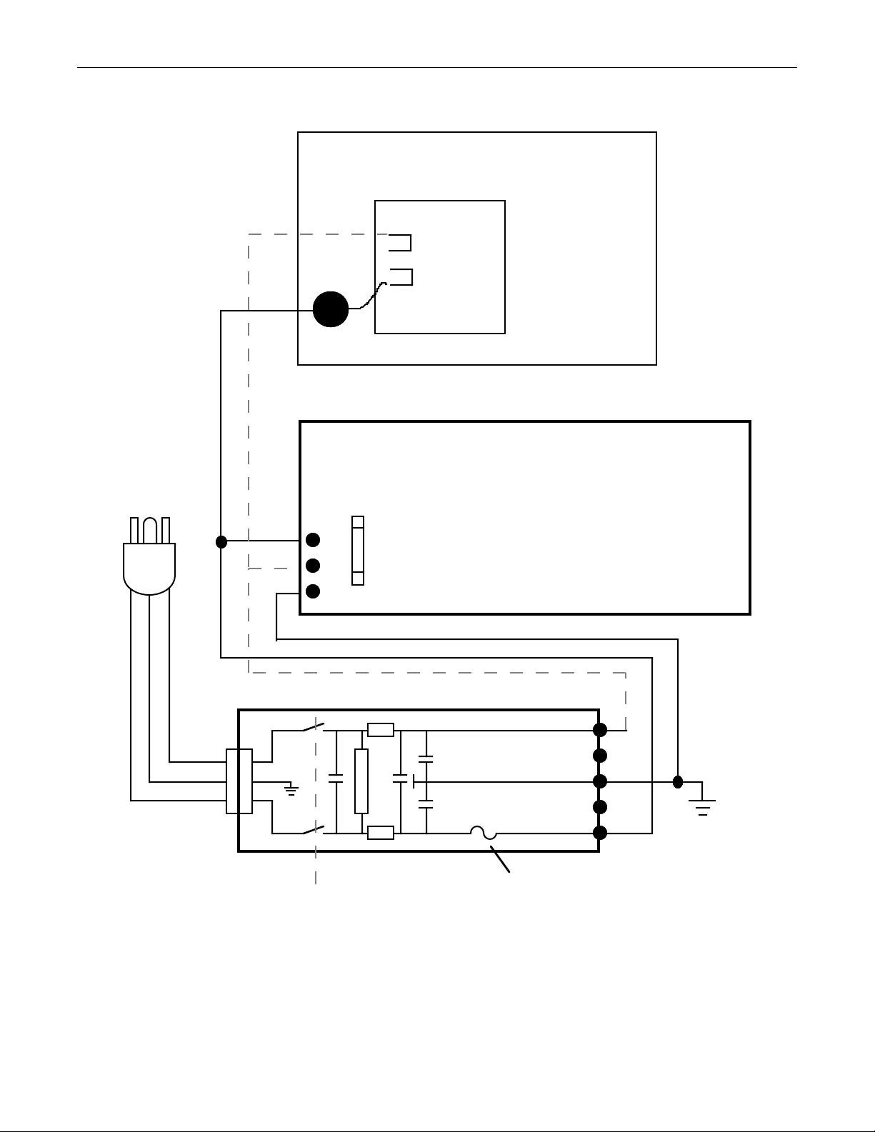
TP8251 PantherPro/46 Image Recorder
Condor HN24-3.6-A+
4
Blu
Brn
1
GROUND
AC NEUTRAL
AC HOT
Fuse
1 Amp for 220VAC
2 Amp for 110VAC
Zenith ZPS 300A
Brown
Blue
Gn/Y
POWER LINE FILTER WITH SWITCH AND FUSE
N
10 Amp
Fuse
2
4
N/C
3
AC Line Cord
P
Main ON/OFF Switch
AC Distribution Diagram
2.5 amp 220VAC
4.0 amp 110VAC
Figure 4-2
N/C
1
Ground
4-2 PrePRESS SOLUTIONS CONFIDENTIAL October 1995
Page 47
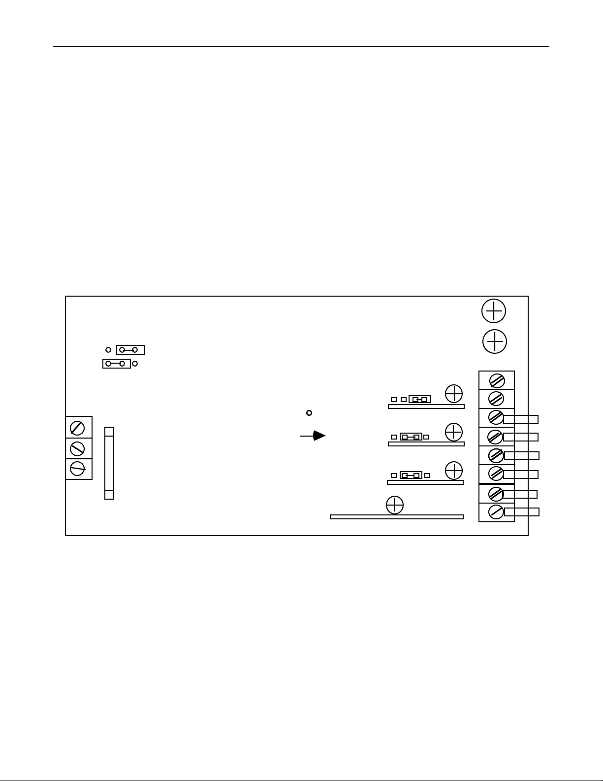
PantherPro/46 Image Recorder TP8251
(
)
4-2 DC Power
The DC power for the PantherPro/46 Image Recorder is generated by two power supplies, a
Zenith and a Condor, located in the electronics chassis.
The Zenith ZPS-300 switching power supply has four separate output channels. A separate
channel for the +5V, +12V, +12V, and -12V DC.
The Zenith ZPS-300 power supply output specifications are as follows:
+5VDC-4.5-45 Amps; +12VDC-.6-6 Amps; –12VDC-1 Amps
AC Input Jumper
SWX2
230V
115V
AC Input
TB1
1
2
3
Fuse
10 Amp
PB Drive +12v Voltage
(measure at PB drive)
+5v
channel 1
Zenith ZPS-300 Power Supply Connection Points
Figure 4-3
TB2 DC Output Connections
TB2-3 +12V BOB/WCB (GRY)
TB2-4 +12V Return BOB/WCB (BLK)
TB2-5 +12V PB Drives (GRY) & Optics Fan (RED)
TB2-6 +12V RTN PB Drives & Optics Fans (BLK)
TB2-7 -12V RTN BOB/WCB & Fans, (BLK)
TB2-8 -12V BOB/WCB & Fans
BLU
+12v
channel 2
+12v
channel 3
-12v
channel 4
+5V
RTN
TB2
1
2
3
4
5
6
7
8
October 1995 PrePRESS SOLUTIONS CONFIDENTIAL 4-3
Page 48

TP8251 PantherPro/46 Image Recorder
The Condor power supply is used to provide +24V DC to the polygon driver PCB, via the
BOB/WCB.
The Condor Power Supply supplies +24 volts to polygon driver board.
7
6
-OUT -S
J2 (+24VDC)
Input
120VAC
Condor
Power Supply
-S +OUT
Transformer Terminals
1-3, 2-4
Jumper
+24VAdj.
To TB-2
Zenith Power Supply
To TB-1
Fuse
Rating
2 amp
Transformer
Terminals
BLU
BRN
5
1
3
2
4
FUSE
240VAC
4-4 PrePRESS SOLUTIONS CONFIDENTIAL October 1995
2-3
Condor Power Supply Connection Points
Figure 4-4
1 amp
Page 49

PantherPro/46 Image Recorder TP8251
Section 5 Installation
DANGER: Laser radiation is present when the recorder optics or supply cassette cover
is open with the safety switches defeated. Avoid direct exposure to beam.
Note: Maintain all Anti-Static procedures for PC boards while performing the installation
procedure.
5-1 Bill of Materials
The PantherPro/46 image recorder is shipped with the following items necessary for
installation:
Line Cord (110V Domestic Only)
Supply Cassette
Take-Up Cassette
Operator Documentation
SCSI Cable (RIP to Recorder)
5-2 Pre-Installation Procedure
5-2.1 Ensure that the site is large enough in square feet to accommodate unpacking,
installation, future service and final machine location before unpacking the unit.
5-2.2 Inspect all shipping cartons for any apparent damage; note any damages on
installation report.
5-2.3 Remove equipment from shipping cartons. Verify contents against Bill of
Materials and Customer Order Form. Note any missing items on installation
report. Items missing and checked as packed should be ordered through
MOCP. Items missing and back ordered should not be ordered through MOCP.
5-2.4 Inspect equipment for any physical damage. Note any damage on installation
report.
5-2.5 Remove the shipping foam and plastic tie wraps from the gate transport area.
Also check for factory final copy. This sample should be compared with copy
quality after unpacking and setup.
Note: Refer to the Panther Preinstallation Guide for additional information.
5-3 Electrical Requirements
Step 1. Verify that the AC outlet to be used meets PrePRESS Solutions' electrical
requirements. (Refer to Section 2 of this manual for electrical requirements.)
Step 2. If the outlet meets the electrical specifications, continue with the installation.
October 1995 PrePRESS SOLUTIONS CONFIDENTIAL 5-1
Page 50

TP8251 PantherPro/46 Image Recorder
Step 3. If the outlet does not meet the electrical requirements, do not proceed with the
installation. Notify the District Service Manager.
5-4 Installation Procedure
Step 1. Position unit in pre-determined final machine location.
Note: The PantherPro/46 is factory tested and ready for installation upon customer
delivery. Skip steps 2 through 15 unless shipping damage is apparent or a malfunction
occurs.
Step 2. Remove the electronics cover.
Step 3. Verify that the main controller board is properly installed to the electronics
compartment.
Step 4. Verify that the plug-in Page Buffer Module(s) are seated properly to the main
controller board (BOB/WCB) with the mounting bracket in place.
Step 5. Inspect all cable connections going to the page buffer drives, Page Buffer
Modules, LCD/Keypad, BOB/WCB, back-light inverter board, and polygon driver
board.
Step 6. Verify power supply AC and DC connections are secure.
Step 7. Verify switch and jumper settings of the main controller board and Page Buffer
Module(s). Refer to Section 7.
Step 8. Remove the optics cover and supply cassette bottom shield. Reseat all cables
connected to the High Speed Laser Amp., High Speed Laser Driver, Polygon
Motor, and SOL/SOL Amp. Assy.
Step 9. Inspect optical bed for any debris or loose components. Verify laser stop block is
positioned against the laser tube assembly. If laser stop block is out of position,
contact Support Services.
Step 10. Make sure that iPantherPro/46 image recorder AC power switch is OFF.
Step 11. Install the AC line cord with the female end into the filter at the rear of unit and the
male end into an approved AC outlet.
Step 12. Turn imagesetter AC power switch ON.
Step 13. Check the laser fan in the optical bed and the cooling fans in the electronics
compartment for proper operation.
Step 14. Check DC voltages with a (recently calibrated) volt meter. If voltages need
adjustment, perform Step 14a.
Step 14a. Adjust the +5, -12, +12, and +12 volts to the following specifications:
5-2 PrePRESS SOLUTIONS CONFIDENTIAL October 1995
Page 51

PantherPro/46 Image Recorder TP8251
+5v +5.1 volts DC +/- .1 volts (channel 1.)
+12v +12.0 volts DC +/- .15volts (channel 2)
+12v +12.0 volts DC +/- .15 volts (channel 3)
Note: channel 3 supplies +12 volts to the page buffer drives. Measure this voltage at the
drive +12 volt power cable.
–12v –12.0 volts DC +/- .15 volts
Note: Refer to Section 8 for the proper channel jumper position and voltage adjustments.
Step 15. Turn power OFF.
5-5 System Test
Step 1. Install starter kit. Adjust take-up cassette for proper media width if necessary.
Refer to Section 8.
Step 2. Turn power ON
Step 3. Execute the Recorder OutPut Module and Controller (page buffer) diagnostics
from the PantherPro/46 front panel. Refer to Section 9. Contact Support Services
if any tests fail.
Step 4. Before connecting the RIP to the image recorder, launch SCSI probe and verify
SCSI address 1 (recorder default) is available for the image recorder SCSI Input
port. If not, change the image recorder SCSI address to one which is available.
This step must be performed on each RIP that is connected to the imagesetter.
Refer to the PantherPro/46 User's Guide for details about the SCSI connections
and RIP setup. After verifying the SCSI address, power down the RIP(s).
Step 5. Change the SCSI address (for each port) on the image recorder, if required, and
power down unit.
Step 6. Connect the RIP(s) to the imagesetter. Also connect the remote diagnostic kit if
required. All Domestic PrePRESS customer PantherPro/46 installations, who
purchase RIP software, will come equipped with a remote diagnostic kit. Refer to
Section 5 (Remote Diagnostics).
Step 7. Power on the PantherPro/46 before powering on the RIPs.
Step 8. If the pin registration punch system is installed, enable the punch option. Refer to
the PantherPro/46 User's Guide if necessary.
Step 9. Run the PantherPro/46 Customer Final Test job. Compare the quality of this test
copy with the customer's final test copy shipped with the recorder. Visually
inspect the different screens, measure line-length and leading, density and
balance, and 50% checkerboard focus.
If the punch option is installed, verify media is punched cleanly and pin
registration is in specification.
October 1995 PrePRESS SOLUTIONS CONFIDENTIAL 5-3
Page 52

TP8251 PantherPro/46 Image Recorder
Store the final test copies for future reference. If image recorder/RIP hardware is
unstable or copy quality is suspect, refer to Section 9. Contact Support Services if
necessary.
5-6 Installation Completion
Step 1. Shut down RIP(s) first and then the image recorder.
Step 2. Re-install covers using the appropriate hardware.
Step 3. Place system in permanent location and level unit.
Step 4. Turn power ON and verify PantherPro/46 recorder software (main application)
and RIP software loads properly.
Step 5. Clean up area.
5-4 PrePRESS SOLUTIONS CONFIDENTIAL October 1995
Page 53

PantherPro/46 Image Recorder TP8251
Section 6 Maintenance
Caution: Use of controls, adjustments or performance of procedures other than those
specified herein, may result in hazardous radiation exposure.
6-1 Periodic Maintenance
The PantherPro/46 image recorder requires a minimal amount of maintenance. Periodically,
based upon environmental conditions and usage, maintenance may be necessary.
6-1.1 Clean
The following checklist is to be used when performing periodic maintenance on the
PantherPro/46 image recorder:
• Covers and panels
• Electronics chassis cooling fans and floor
• Media transport area, chaff tray, and rollers (normally performed by customer)
• Optics bed floor and optics* (polygon scanner facets, first cylinder lens, cylinder
lens, beam steering mirror, laser fan/filter)
6-1.2 Check
Check the following items when performing periodic maintenance on the PantherPro/46
image recorder:
• Light shielding material
• Power knife carriage
• Spur gear and worm gear lubricant
• Adjustable clutch
6-2 Optics Cleaning Procedures
General Overview
In certain environments it is possible that the PantherPro/46 optics may become
coated with a thin film or dirt which may require cleaning. The source of this film could
be from cigarette smoke or processor chemical fumes. In the case of processor fumes
condensing on the facets/lenses, if not cleaned off it could cause pitting which may
require part replacement.
Typically, in cases where density variation across the media width exists and all other
avenues (light shielding material, media, chemistry) have been explored to resolve
this condition, it is possible that the facets or lenses (scan, Ist cylinder, and 2nd
cylinder) may need cleaning.
Note: The optics cleaning procedure(s) may be performed only if dirt
cannot be removed with an optics approved air duster.
October 1995 PrePRESS SOLUTIONS CONFIDENTIAL 6-1
Page 54

TP8251 PantherPro/46 Image Recorder
Note: Only polygons with the silicon oxide coated facets (silver in color) can be
successfully cleaned using the procedure outlined below. Gold coated facets
were not used in the PantherPro/46 image recorder.
6-2.1 Polygon Scanner Facets
Material
• Lens cleaning tissue
• 99% minimum purity isopropyl alcohol.
Procedure
NOTE: Maintain all Anti static Replacement/Removal Procedures for PC boards
while performing these procedures.
NOTE: Pay attention to the location of any cables that are removed so that they
can be easily re-installed later.
NOTE: Since 99% pure alcohol is to be used, be sure to work in a well ventilated
area.
Step 1. Power down the system and allow the polygon to stop rotating.
Step 2. Remove the optics cover. Refer to Section 7, if necessary.
Step 3. Disconnect all power and signal harnesses associated with the
polygon.
Step 4. Remove the three screws which hold the polygon in place.
Step 5. Carefully remove the polygon assembly and place it on a flat surface
with the facets facing up. DO NOT touch the facet surface with
your hands as this will leave oils on the mirror surface.
Step 6. Place the lens cleaning tissue over the facet.
Step 7. Drip isopropyl alcohol on the tissue until it is soaked and in full contact
with the facet surface.
Step 8. Slide the tissue across the facet surface without lifting it. This should
minimize streaking.
Step 9. Repeat steps 6 through 8 for all eight (8) facets using the polygon
flywheel located below the facet mirrors to rotate between facets.
Step 10. Polygon facet cleaning is now complete.
Step 11. Re-install the polygon assembly by reversing steps one through four.
6-2 PrePRESS SOLUTIONS CONFIDENTIAL October 1995
Page 55

PantherPro/46 Image Recorder TP8251
Step 12. Run copy and inspect image to determine if density variation meets
specification.
6-2.2 Scan Lens
Material
• Lens cleaning tissue
• 99% minimum purity isopropyl alcohol.
Procedure
NOTE: Maintain all Anti static Replacement/Removal Procedures for PC boards
while performing these procedures.
NOTE: Since 99% pure alcohol is to be used, be sure to work in a well ventilated
area.
Step 1. Power down the system.
Step 2. Remove the optics cover. Refer to Section 7, if necessary.
Step 3. Remove the scan lens. Refer to Section 7, if necessary.
Step 4. Carefully remove the scan lens and place it on a flat surface.
DO NOT touch the front or rear lens surface with
your hands, as this will leave oils on the surface.
Step 5. Place the lens cleaning tissue over the front lens.
Step 6. Drip isopropyl alcohol on the tissue until it is soaked and in full contact
with the lens surface.
Step 7. Slide the tissue across the lens surface without lifting it. This should
minimize streaking.
Step 8. Repeat steps 6 through 8 for the rear side of the scan lens.
Step 9. Scan lens cleaning is now complete.
Step 10. Re-install the scan lens by reversing steps one through four
above.
Step 11. Run copy and inspect image to determine if density variation meets
specification.
October 1995 PrePRESS SOLUTIONS CONFIDENTIAL 6-3
Page 56

TP8251 PantherPro/46 Image Recorder
6-2.3 Second Cylinder Lens
Material
• Lens cleaning tissue
• 99% minimum purity isopropyl alcohol
Procedure
NOTE: Be careful not to damage SOL Sensor when removing supply cassette
bottom shield.
NOTE: Maintain all Anti static Replacement/Removal Procedures for PC boards
while performing these procedures.
NOTE: Since 99% pure alcohol is to be used, be sure to work in a well ventilated
area.
Step 1. Power down the system.
Step 2. Open the supply cassette cover and remove the supply cassette.
Step 3. Remove the supply cassette bottom shield. Refer to Section 7, if necessary.
Step 4. Using a flash light, check the 2nd cylinder lens front and rear for dirt or
imperfections.
Step 5. While the 2nd cylinder lens is in place, dampen the lens tissue with
99% pure alcohol and carefully wipe the front and rear side of the 2nd
cylinder lens. Be careful not to damage the 2nd cylinder mask or scratch
the lens.
Step 6. Using a flashlight, recheck the 2nd cylinder lens for dirt or imperfections.
Step 7. The 2nd cylinder cleaning is now complete.
Step 8. Run copy quality test and inspect image to determine if vertical
banding/artifacts are evident.
6-4 PrePRESS SOLUTIONS CONFIDENTIAL October 1995
Page 57

PantherPro/46 Image Recorder TP8251
6-2.4 First Cylinder Lens
Material
• Lens cleaning tissue
• 99% minimum purity isopropyl alcohol or Optical Surface Cleaner
Procedure
NOTE: Maintain all Anti static Replacement/Removal Procedures for PC boards
while performing these procedures.
NOTE: Since 99% pure alcohol is to be used, be sure to work in a well ventilated
area.
Step 1. Power down the system.
Step 2. Remove the optics cover. Refer to Section 7, if necessary.
Step 3. Using a flash light, check the first cylinder lens for dirt or imperfections.
Step 4. While the first cylinder lens is in place, dampen the lens tissue with 99%
pure alcohol and carefully wipe the front and rear side of the lens.
Step 5. The first cylinder cleaning is now complete.
Step 6. Run copy quality test and inspect image for artifacts.
6-2.5 Beam Steering Mirror
Material
• Lens cleaning tissue
• 99% minimum purity isopropyl alcohol or Optical Surface Cleaner
Procedure
NOTE: Maintain all Anti static Replacement/Removal Procedures for PC boards
while performing these procedures.
NOTE: Pay attention to the location of any cables that are removed so that they
can be easily re-installed later.
NOTE: Since 99% pure alcohol is to be used, be sure to work in a well ventilated
area.
Step 1. Power down the system.
Step 2. Open the supply cassette cover and remove the supply cassette.
October 1995 PrePRESS SOLUTIONS CONFIDENTIAL 6-5
Page 58

TP8251 PantherPro/46 Image Recorder
Step 3. Remove the supply cassette bottom shield. Refer to Section 7, if necessary.
Step 4. Using a flash light, check the beam steering mirror for dirt or imperfections.
Step 5. While the beam steering mirror is in place, dampen the lens tissue with
99% pure alcohol and carefully wipe the front side of the mirror.
Step 6. The beam steering mirror cleaning is now complete.
Step 7. Run copy quality test and inspect image for artifacts.
6-3 Adjustable Clutch
The clutch is designed to exert constant tension and smooth media feed. The tension of the
adjustable clutch is set between 35 - 40 ounces at the factory. Before measuring or adjusting
the clutch, perform the following steps:
Step 1. Output the PantherPro/46 "Customer Final Copy" test (PostScript file) and check for
banding and other copy quality issues. The "Final Customer Copy" test file is
available on the PrePRESS SOLUTIONS BBS.
Step 2. If possible, locate the customer's original "Customer Final Copy" sample, which is
shipped with the PantherPro/46. Use this original sample as a "benchmark" and
compare it to the "Customer Final Copy" output produced in Step 1.
Step 3. If the PantherPro/46 "Customer Final Copy" test (postscript file) output performed in
step 1 is not within "benchmark", proceed to section 6-3.1.
Note: Mark and save the output samples for future reference.
6-6 PrePRESS SOLUTIONS CONFIDENTIAL October 1995
Page 59
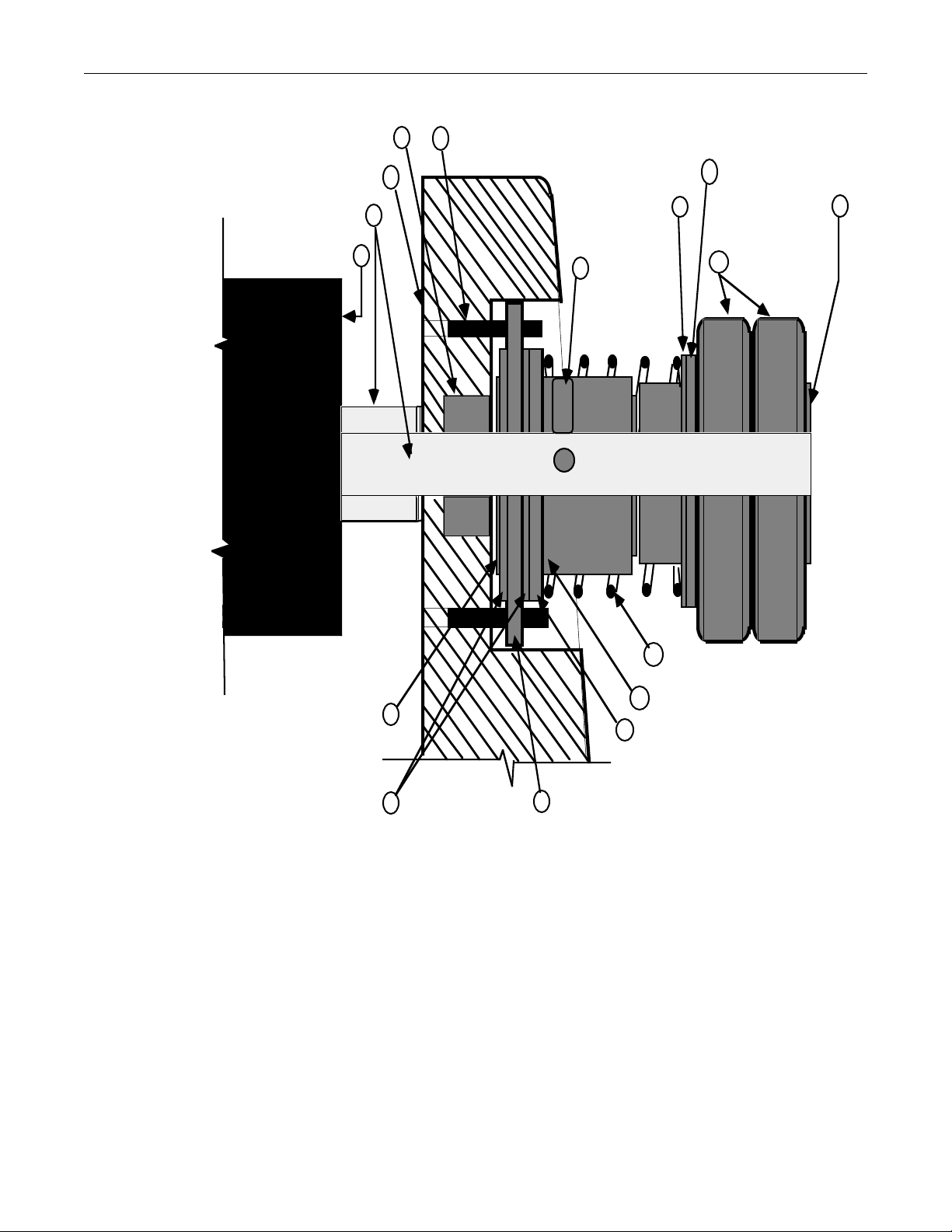
PantherPro/46 Image Recorder TP8251
Ball Bearing
Image Recorder Base
Drag Roller Shaft
Drag Roller (rubber) 12
13
14
15
Clutch Mounting Pins (3)
16
Neoprene Washer
Cup Point
5
Set Screw (2)
Washer
10
8
Clutch Adapter Shaft
Knurled Hand Nut
9
11
7
Compression
Spring
6
Clutch Collet
1
Teflon Flat Washer
2
3
Clutch Plate
NeopreneWasher
4
Stainless Steel
Washer
Adjustable Clutch Side View
Figure 6-1
Note: Item 8 is not required.
6-3.1 Clutch Tension Set-Up Procedure
Note: To check/set the adjustable clutch tension, use a precision tension (strain) gauge.
Ensure gauge is calibrated and is sensitive enough to measure ounces (1/16 lb.). For
details, refer to Figure 6-2.
Step 1. Use a 2 to 3 foot length of string and wrap it neatly around the drag roller as
shown in Figure 6-2.
October 1995 PrePRESS SOLUTIONS CONFIDENTIAL 6-7
Page 60
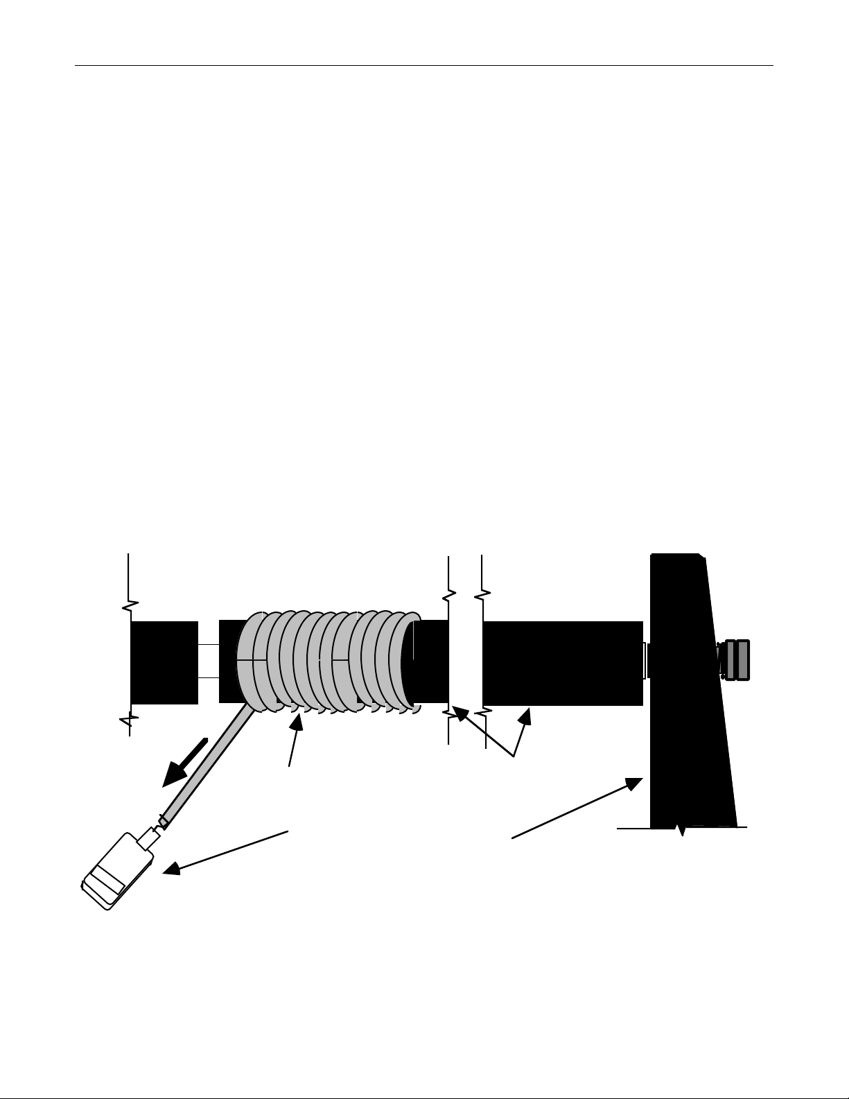
TP8251 PantherPro/46 Image Recorder
Note: The adjustable clutch comes factory set to provide 35 - 40 ounces of tension.
Step 2. Attach the strain gauge to the string and perform pull test. It should be a constant,
smooth pull action measuring near but not exceeding 40 ounces.
Note: The clutch tension may be fine tuned (up to 40 ounces) as needed, by adjusting the
inner knurled hand nut position on the adjustable clutch. (Refer to Figure 6-1, item #9).
The tension nut is the inside nut and the locking nut is the outside nut.
Step 3. Turn the locking nut counter-clockwise while holding the tension nut in place.
(This will allow the tension nut to be adjusted as needed.)
Step 4. Hold the drag roller steady and adjust the tension ring as needed. (Turning the
tension ring clockwise will increase the drag roller and clutch tension.)
Step 5. After adjusting tension nut, hold tension nut in place and tighten (clockwise) the
locking nut to secure clutch adjustment. .
Step 6. Measure clutch tension.
Step 7. Repeat steps 3 through 6 until the clutch tension is set between 35-40 ounces.
Step 8. Output the PantherPro/46 "Customer Final Copy" test (postscript file) " and
compare to the original samples. Contact Support Services if necessary.
String
Drag Roller
Tension Gauge
Image Recorder Base
00.00
Adjustable Clutch Tension Check
Figure 6-2
6-4 Safety Considerations
6-8 PrePRESS SOLUTIONS CONFIDENTIAL October 1995
Page 61

PantherPro/46 Image Recorder TP8251
When performing maintenance routines at the customer's facility, service personnel will
ensure the safety of themselves, customer personnel and the equipment.
Maintenance often requires the removal of safety features and covers, creating potential
hazards. Ensure that all personnel in the work area are aware of and stay away from these
potential hazards.
The following list presents the most important safety considerations:
A. Caution - Use of controls or adjustments or performance of procedures other than those
specified herein may result in hazardous radiation exposure.
B. Observe all electrical and mechanical safety precautions while working on machines that
have covers and panels removed and electrical components exposed.
C. Post a notice indicating that the machine is undergoing service.
D. Prevent accidental operation of the machine under service by turning off power switches
and disconnecting the ac power line cable.
E. Do not leave tools where they might cause harm to personnel and/or damage to the
machines.
F. Keep toxic, flammable and/or abrasive substances secure in their respective containers.
G. Do not wear loose clothing when performing maintenance service on any machine. Long
hair should be tied back and secured in place.
H. Report all unsafe practices to the customer's office supervisor and to your Service
Manager immediately.
I. Do not attempt any maintenance activity without the proper tools and corresponding
support documentation.
J. Upon completion of maintenance, ensure that all safety covers, panels, and devices are
replaced and fully operational.
K. Test operate machines before returning them to customer use.
October 1995 PrePRESS SOLUTIONS CONFIDENTIAL 6-9
Page 62

PantherPro/46 Image Recorder TP8251
Section 7 Removal/Replacement
DANGER - Visible red laser radiation is present when the optics cover or supply
cassette cover is open with the safety switch defeated. Avoid direct exposure to beam.
CAUTION - Use of controls or adjustments or performance of procedures other than
those specified herein may result in hazardous radiation exposure.
CAUTION: Remove recorder AC power cord before removing power supply from
electronics chassis.
NOTE - Maintain all anti-static procedures while performing removal/replacement
procedures on PC boards or electronics components.
7-1 External Covers and Panels
The external covers and panels of the PantherPro/46 can be identified by referring to Figure
7-1.
A-Electronics Cover
B-Front Bezel
C-Front Panel
D-Optics Cover
E-Supply Cassette Door Stay Arm
F-Supply Cassette Door
G-Take-up Cassette Door
H-Right End Panel
I-Rear Access Panel
J-Rear Cover
K-Storage Compartment Door
L-Lower Right Panel
October 1995 PrePRESS SOLUTIONS CONFIDENTIAL 7-1
Page 63
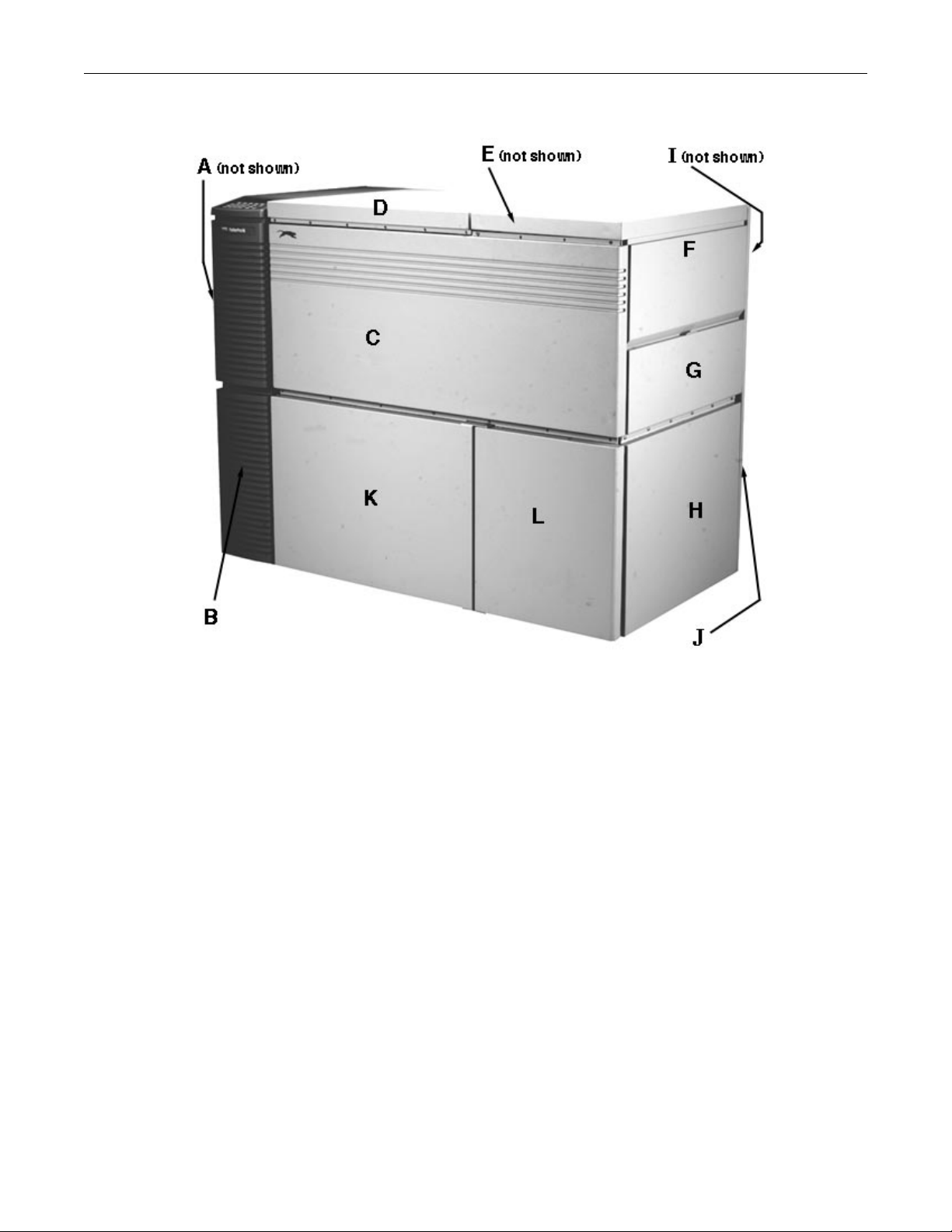
TP8251 PantherPro/46 Image Recorder
PantherPro/46 External Covers
Figure 7-1
7-1.A Electronics Cover
Step 1. Remove the electronics (magnetic) screw cover which is located at the top of the
electronics cover.
Step 2. Remove the 5 top screws and 5 bottom screws that fasten the electronics cover to
the electronics chassis.
Note: Hold electronics cover securely in place while removing the last screw.
Step 3. Replace electronics cover in reverse order of removal.
7-1.B Front Bezel/LCD Keypad
Step 1. Remove the electronics cover. Refer to 7-1.A.
Step 2. Detach the BOB/WCB keypad cable (in the electronics chassis) from the keypad
flat cable.
7-2 PrePRESS SOLUTIONS CONFIDENTIAL October 1995
Page 64

PantherPro/46 Image Recorder TP8251
Step 3. Remove the 8 screws that fasten the front bezel to the electronics chassis. (Six of
the scows are located in the front side of the electronics chassis. The remaining
two screws are located in the top side of the electronics chassis.)
Step 4. Carefully remove the front bezel to gain access to the LCD shield and ground
wire. (The LCD (sheet metal) shield is located below the top right corner of the
LCD.
Note: The keypad grounding wire is approximately 6 inches long.
Step 5. Loosen the LCD shield to allow the keypad flat cable to be pulled out through the
slot in the electronics chassis. (The LCD shield securing screw is accessed from
inside the electronics chassis, under the LCD.)
Step 6. Remove keypad/LCD grounding nut to free keypad ground wire.
Step 7. Remove the front bezel. If necessary, replace keypad at this time.
Step 8. Replace the front bezel, and keypad, in reverse order of removal. Be careful not
to crimp the keypad flat cable when replacing front bezel. .
7-1.C Front Panel
Step 1. Remove the upper row of screws (5) that secure the front cover to the main
bulkhead. (Two of the upper row of screws are located in the optics area and the
remaining three are located in the media transport area.)
Note: In the earlier units there are three rows of screws that secure the front panel to the
main bulkhead. The middle and top row are somewhat difficult to remove because the
screws are locating behind the insulating foam. Cut a slit in the foam where the screw
heads are located to facilitate removal.
Step 2. Remove the lower row of screws (7) located at the bottom of the front cover.
Step 3. Replace front cover in reverse order of removal.
7-1.D Optics Cover
Step 1. Remove the optics (magnetic) screw cover.
Step 2. Remove the 6 screws that secure the optics cover to the main bulkhead. .
Step 3. Slide optics cover forward to dislodge the two rear guide pins from the rear panel.
Step 4. Firmly grasp the front and rear of optics cover and lift off.
Step 5. Replace optics cover in reverse order of removal.
7-1.E Supply Cassette Door Stay Arm
Step 1. Lift supply cassette cover and secure in open position.
October 1995 PrePRESS SOLUTIONS CONFIDENTIAL 7-3
Page 65

TP8251 PantherPro/46 Image Recorder
Step 2. Hold stay arm in up position and remove shoulder screw that attaches stay arm to
supply cassette door. Continue to hold stay arm in up position.
Step 3. Rotate flat (inner) side of stay arm towards rear cover and lift up to dislodge L-
section of stay arm from slot.
Step 4. Replace stay arm in reverse order of removal.
7-1.F Supply Cassette Door
Step 1. Remove supply cassette door stay arm. (Refer to 7-1.E.)
Step 2. Remove the 6 screws that secure the supply cassette door to the upper light
shield. Screws are located behind the sound absorbing pad fastened to the
upper light shield.
Step 3. Replace rear cover in reverse order of removal.
7-1.G Take-up Cassette Door
Step 1. Open the take-up cassette door.
Step 2. Remove the shoulder screw that mounts the support wire cable (lanyard) to the
door.
Step 3. Close the take-up cassette door.
Step 4. Remove the 6 screws that mount the door to the main frame.
Step 5. Replace take-up cassette door in reverse order of removal.
Step 6. Adjust take-up cassette door vertical position, if necessary, to ensure proper
closure.
7-1.H Right End Panel
Step 1. Remove the take-up cassette door. Refer to 7-1.G.
Step 2. Remove the 2 self tapping screws located below the side panel.
Step 3. Replace the right end panel in reverse order of removal.
I Rear Access Panel
7-1.
Step 1. Remove the 10 screws that secure the rear access panel to the rear panel.
Step 2. Replace the rear access panel in reverse order of removal.
7-1.J Rear Panel
Note: A total of 13 screws, 2 of which are half turn hanger screws, secure the rear cover
to the main chassis.
7-4 PrePRESS SOLUTIONS CONFIDENTIAL October 1995
Page 66

PantherPro/46 Image Recorder TP8251
Step 1. Remove the 11 screws that secure the rear panel to the main chassis. One screw
is accessed through a hole on the upper right area of the panel.
Step 2. Remove the 2 hanger screws that are accessed through a hole in the lower left
and right side rear panel.
Step 3. Replace rear panel in reverse order of removal.
7-1.K Storage Compartment Door
Step 1. Remove the upper and lower shoulder screw which secures the storage
compartment door to the lower right panel.
Step 2. Replace the storage compartment door in reverse order of removal.
7-1.L Lower Right Panel
Step 1. Remove the 6 screws which secure the lower right panel to the main frame. (One
screw is located in the top right corner of the panel, and accessed from the inside
of storage compartment. Three screws are located behind the left side of the
panel, and accessed at the storage compartment entrance. The last two screws
are located under the right panel.)
Step 2. Replace the storage compartment door in reverse order of removal.
7-2 Page Buffer Module(s)
Step 1. Remove the electronics cover. Refer to 7-1.A.
Step 2. Remove the Page Buffer Module SCSI ribbon cable connector.
Step 3. Remove the screw(s) that secure the Page Buffer Module to the page buffer
bracket(s).
Step 4. Repeat steps 2 and 3 for each additional Page Buffer Module to be removed.
Step 5. Replace Page Buffer Module(s) in reverse order of removal.
7-3 Big Output Board/WCB
Step 1. Remove all Page Buffer Modules. Refer to 7-2.
Step 2. Remove all cables connected to the BOB/WCB.
Step 3. Remove the 8 screws which secure the BOB/WCB I/O panel to the rear panel.
Step 4. Remove the 5 screws which secure the BOB/WCB to the electronics chassis.
Step 5. Place BOB/WCB on a grounded anti-static mat. Remove the 18 screws that
secure the I/O panel to the BOB/WCB.
Note: All screws are not the same type snd size.
October 1995 PrePRESS SOLUTIONS CONFIDENTIAL 7-5
Page 67

TP8251 PantherPro/46 Image Recorder
Step 6. Replace BOB/WCB in reverse order of removal.
7-4 Page Buffer (PB) Disk Drives
Note 1: Front drive removal - PB disk drives positioned to the front of the drive mount
cage are secured in place with 4 screws and stand-offs.
Note 2: Rear Drive removal - PB disk drives positioned to the rear of the drive mount
cage are secured in place with 2 screws and a support bracket. To facilitate removal of
rear drive, remove front drive as described above in note 1.
Step 1. Remove electronics cover. Refer to 7-1.A.
Step 2. Remove SCSI cable connector(s) from PB disk drive(s).
Step 3. Separate the velcro loop from the velcro hook and move the page buffer disk
drive SCSI cable(s) away from drive mount cage.
Step 4. To remove a PB disk drive positioned to the front of the drive mount cage, refer to
Note 1.
Step 5. To remove a PB disk drive positioned to the rear of the drive mount cage, refer to
Note 2.
Step 6. Replace PB disk drive(s) in reverse order of removal using mounting hardware
from original PB drive(s).
7-5 LCD and Terminator PCB
Note: The Terminator PCB is a daughter board of the LCD.
Step 1. Remove front bezel. Refer to 7-1.B.
Step 2. Remove the three LCD mounting screws which are fastened to the stand-offs.
Step 3. Remove the LCD ground wire from ground post.
Step 4. Lift up the LCD/Terminator PCB and disconnect the BOB/WCB to LCD ribbon
cable from the rear side.
Step 5. Remove the screw which secures the Terminator PCB to the LCD.
Step 6. Replace LCD and/or the Terminator PCB in reverse order of removal.
7-6 LCD Inverter PCB
Step 1. Remove the electronics cover. Refer to 7-1.A.
Step 2. Disconnect the cables from the inverter PCB.
7-6 PrePRESS SOLUTIONS CONFIDENTIAL October 1995
Page 68

PantherPro/46 Image Recorder TP8251
Step 3. Remove the inverter PCB mounting screws.
Step 4. Replace inverter PCB in reverse order of removal.
7-7 Polygon Driver PCB/Motor Assembly
Note 1: The motor spins for several minutes after power has been turned off. Do not
remove polygon motor assembly until it has fully stopped.
Note 2: The polygon motor assembly and polygon driver PCB are a matched set and
must be replaced together. To be more specific, the serial number on the polygon
housing must match the serial number on the speed correction PAL, which is located in
socket (U4) on the polygon driver PCB.
Caution: The coating on the polygon mirror surface is delicate. Do not touch facet
mirrors. Refer to the Section 6 for polygon facet cleaning procedure if necessary.
Step 1. Remove the electronics cover. Refer to 7-1.A.
Step 2. Remove the cables connected to the polygon driver PCB.
Step 3. Remove the optics cover. Refer to 7-1.C.
Step 4. Remove the cables connected to the polygon motor assembly.
Step 5. Remove the polygon motor assembly by removing the three large hex head
mounting screws.
Step 6. Remove the polygon driver driver PCB by removing the two mounting screws.
Step 7. Remove the polygon driver PCB to polygon motor assembly cables. Be careful
not to damage the light shielding material located in the electronics chassis
(polygon) cable pass through hole.
Step 8. Replace the polygon driver/motor assembly in the reverse order of removal.
7-8 Zenith ZPS-300 Power Supply
Step 1. Remove the electronics cover. Refer to 7-1.A.
Step 2. Remove the wires attached to TB1(AC) and TB2(DC) of the ZPS-300 power
supply. Note position of wires or refer to Section 4.
Step 3. Disconnect the Condor power supply DC connector P2.
Step 4. Hold the power supply mounting tray in place while removing the four screws that
secure the power supply mounting tray to the electronics chassis.
Step 5. Remove the screws that secure the ZPS-300 power supply to the mounting tray.
October 1995 PrePRESS SOLUTIONS CONFIDENTIAL 7-7
Page 69

TP8251 PantherPro/46 Image Recorder
Step 6. Replace the ZPS-300 power supply and connections in reverse order of removal.
7-9 Condor Power Supply
Step 1. Remove the electronics cover. Refer to 7-1.A.
Step 2. Remove the Condor power supply DC connector P2.
Step 3. Remove the Condor power supply AC wires that are connected to the Zenith
power supply AC input (TB1).
Step 4. While holding power supply mounting tray in place, remove the four screws that
secure the power supply mounting tray to the electronics chassis.
Step 5. Remove the screws that secure the Condor power supply to the mounting tray.
Step 6. Replace the Condor power supply in reverse order of removal.
7-10 Cooling Fan Assembly
Step 1. Remove the electronics cover. Refer to 7-1.A.
Step 2. Remove the front bezel/LCD keypad. Refer to 7-1.B
Step 3. Disconnect -12 volt cable from fan assembly.
Step 4. Remove the four screws that secure the fan assembly to the electronics chassis.
Step 5. Replace fan(s) as required.
Step 6. Replace the fan assembly in reverse order of removal.
7-11 High Speed Laser Amplifier (HSLA) PCB
Step 1. Remove the Optics Cover. Refer to figure 7-1.D.
Step 2. Remove the three cables connected to the HSLA PCB.
Step 3. Remove the two mounting nuts which hold the HSLA PCB to main frame.
Step 4. Lift the HSLA PCB out of optics area and place in an anti-static bag.
Step 5. Replace the HSLA PCB in the reverse order of removal.
7-12 Laser Fan (Retrofit Kit) Assembly
Step 1. Remove the Optics Cover. Refer to section 7-1.D.
Step 2. Remove the electronics cover. Refer to section 7-1.A
Step 3. Remove the laser fan +12 volt cable from the Zenith ZPS-300 power supply.
7-8 PrePRESS SOLUTIONS CONFIDENTIAL October 1995
Page 70

PantherPro/46 Image Recorder TP8251
Step 4. Remove the laser fan bracket/laser cover mounting screw.
Step 5. Lift the laser fan assembly away from optics area and replace parts as required.
Step 6. Replace the laser fan assembly in reverse order of removal.
7-13 SOL/SOL Amplifier Assembly
Step 1. Open the supply cassette door.
Step 2. Open gate and remove supply cassette.
Step 3. Remove the four screws that secure the supply cassette bottom shield to the base
casting. (Some units may only have two screws which secure the supply cassette
bottom shield to the base casting.)
Step 4. Carefully lift the supply cassette bottom shield upward away from SOL sensor
and disconnect smart cassette memory cable from main harness.
Step 5. Remove the SOL cable connector from the SOL sensor. Note that the black wire
of connector is facing up.
Step 6. Remove the two screws that mount the SOL Sensor to the bracket. Note the
position of SOL bracket.
Step 7. Remove the two screws which secure the SOL/SOL Amplifier assembly to the
mounting bracket.
Note: Save mounting bracket for replacement SOL/SOL Amplifier Assy.
Step 8. Replace the SOL/SOL Amplifier in reverse order of removal.
7-14 High Speed Laser Driver/Laser Tube Assembly (Refer to Figure 7-2)
Step 1. Remove the optics cover. Refer to 7-1.D.
Step 2. Remove the four screws which secure the laser diode cover and laser fan
(bracket) assembly, if present, to the base casting. .
Step 3. Disconnect the cable from the HSLD PCB.
Step 4. Verify the laser diode/tube assembly is positioned firmly against the stop block.
Step 5. Loosen the two screws on the mounting clamp.
Step 6. Remove the laser diode tube assembly mounting screw.
Step 7. Carefully remove laser diode assembly. Be careful to not touch the scan lens.
Step 8. Replace the laser diode assembly in reverse order of removal. Position the laser
diode assembly against the ramp side (toward the rear panel) and firmly against
October 1995 PrePRESS SOLUTIONS CONFIDENTIAL 7-9
Page 71

TP8251 PantherPro/46 Image Recorder
the stop block before tightening the mounting clamp (wedge) screws and laser
diode assembly mounting screw.
LASER
MOUNTING
CLAMP
DRIVER PCB
RIBBON CABLE
CONNECTOR
LASER DIODE
TUBE ASSEMBLY
MOUNTING
SCREWS
STOP
BLOCK
MOUNTING
SCREW
MOUNTING
SCREW
Laser Diode Assembly
Figure 7-2
7-15 Second Cylinder Lens Assembly (Refer to Figure 7-3)
Step 1. Open the supply cassette door.
Step 2. Remove the four screw (two in some earlier units) which secure the supply
cassette bottom shield to the base casting. Be careful not to damage the
SOL/SOL amplifier assembly.
Step 3. Carefully lift supply cassette shield away from SOL sensor and disconnect the
smart cassette memory cable from main harness.
Note: Observe the (left to right) position of the second cylinder lens in respect to the left
most pin.
Step 4. Remove the two second cylinder lens spring and clip assemblies.
Step 5. Carefully loosen one of the two hex nuts to allow the second cylinder
lens to move (spring) away from the base casting mounting pin.
After the lens has moved away from the pin, hand tighten the hex nut to insure the
lens will remain in a vertical position when the other hex nut is loosened.
Step 6. Carefully loosen the hex nut on the opposite end of second cylinder lens and
slide "L" bracket about 0.25 inches away from lens.
7-10 PrePRESS SOLUTIONS CONFIDENTIAL October 1995
Page 72

PantherPro/46 Image Recorder TP8251
Step 7 Carefully remove second cylinder lens mask.
Step 9. Hold the second cylinder lens by the ends and carefully lift it away from casting.
Wrap second cylinder lens in tissue paper and rest safely on table.
Step 10. Carefully replace second cylinder lens in reverse order of removal. Follow the
replacement tips outlined below:
• Position second cylinder lens in the center of image area, between the two
outer pins.
• Make sure the black dot on the center edge of lens is facing down toward
base casting with the convex face of 2nd cylinder lens facing away from the
mounting pins.
• Place mask between the flat side of the 2nd cylinder lens and the pins with
the wide portion of mask positioned against the base casting.
• The final mask position requires the mask opening to be approximately
3/16 of an inch away from the left most base casting mounting pin (on
SOL side), to ensure laser beam will not reflect off of the pin.
• When securing the 2nd cylinder lens against the mounting pins with the "L"
bracket, make sure the face of the hex nut will not reflect the laser beam into
the lens. Refer to Figure 7-3.
October 1995 PrePRESS SOLUTIONS CONFIDENTIAL 7-11
Page 73

TP8251 PantherPro/46 Image Recorder
Second Cylinder Lens and Start of Line Sensor Assembly
Figure 7-3
7-16 Scan Lens (For Cleaning Purposes Only)
Step 1. Remove the optics cover. Refer to 7-1.D.
Step 2. Note the position (12 o'clock) of the reference dot located on the scan lens
housing.
Step 3. While holding the scan lens in place, loosen the two screw that secure the scan
lens housing to the base casting.
Step 4. Lift scan lens away from base casting.
Step 5. Inspect scan lens for dirt. Refer to the optics cleaning procedure in Section 6 if
needed.
Step 6. Replace scan lens in reverse order of removal.
7-12 PrePRESS SOLUTIONS CONFIDENTIAL October 1995
Page 74

PantherPro/46 Image Recorder TP8251
7-17 Gate Assembly (Refer to Figure 7- 4)
Step 1. Open the take-up cassette and supply cassette door.
Step 2. Remove the rear access panel. Refer to 7-1.
Step 3. Locate the gate cable connections. (Gates which have a punch option
installed will have an additional cable connector and ground wire for the punch
motor/home switch cable.
If the gate assembly being replaced does not have a punch skip
step 4.
Step 4. Disconnect the punch motor/home switch cable connector and ground wire.
Step 5. Disconnect the media out switch cable connector and ground wire.
Step 6. Remove plastic tie wrap(s) or cable clamp from the cable guard.
Step 7. Loosen the set screws that secure the gate registration pin (right side) and
the gate retaining pin (left side).
Step 8. While holding gate securely, open latches and slide gate assembly side to
slide to dislodge (registration and retaining) pins. Once the pins are
displaced, remove gate assembly without damaging cables.
Step 9. Put the replacement gate assembly into position.
I.
Step 10. Assemble registration pin with the head flush to the base casting surface. Secure
registration pin set screw. Slide right end plate of gate assembly onto pin.
Step 11. Use retaining pin to position gate assembly against registration pin and lock in
place using retaining pin set screw.
Step 12. Make certain gate pivots freely with no side to side movement.
If new gate does not have a punch, skip step 13.
Step 13. Connect the punch motor/home switch cable to main harness.
Step 14. Reconnect the media out switch cable to main harness.
Step 15. Secure media out switch and punch motor (if installed) ground wires to upper
gearbox mounting screw.
Step 16. Use a plastic tie wrap or cable clamp to secure the gate cables to cable guard.
Step 17. Before replacing rear access panel, utilize the manual feed switch to verify media
will move through media transport properly. If a punch system is installed, run the
October 1995 PrePRESS SOLUTIONS CONFIDENTIAL 7-13
Page 75
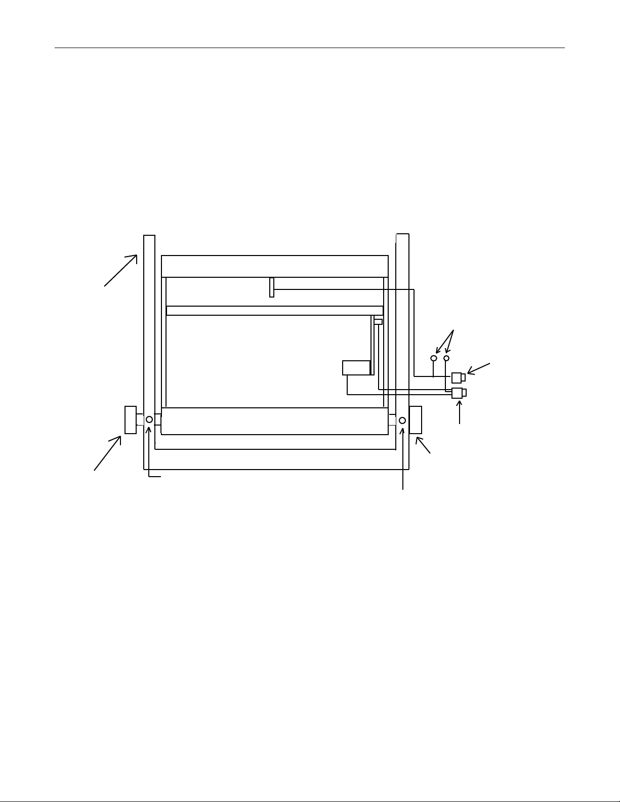
TP8251 PantherPro/46 Image Recorder
s
disk based ROPM diagnostic punch test. Verify that the punch system will cycle
and punch properly.
Step 18. If a punch system is installed, enable the media punch via the recorder control
panel. Select a resolution that the customer will most often use. Output the
PantherPro/46 copy quality test page four times and check for registration
to be in specification.
X1
:
X1
Figure 1
Optical Bed
Retaining Pin
Lock Shoulder
Lock sholder
Registration Pin
Lock Shoulder
Lock Shoulder
The distance (X1), must be equal to the distance (X2).
The distance (X1), must be equal to the distance (X2).
The distance X1 must be equal to the distance X2
Registration Pin Set Screw
Lock sholder set screw
Lock Shoulder Set Screw
Retaining Pin Set Screw
Lock Shoulder Set Screw
Lock Shoulder Set Screw
Lock Shoulder Set Screw
Lock Shoulder Set Screw
Lock Shoulder Set Screw
X2
X2
Cutter Home Switch
Cutter Home Switch CableBase Casting
Ground Wire Ring Lug
Media Out Switch
Cable Connector
Cutter Motor Cable
Punch Motor/Home
Switch Cable Connector
Gate Registration Pin
Gate Registration Pin Set Screw
Gate Assembly
Figure 7-4
7-18 Drag-Pinch Roller
Step 1. Open supply cassette cover.
Step 2. Loosen the pinch roller bracket mounting screws from one side while holding
pinch roller in place.
Step 3. Place hand under bracket to catch the pinch roller arm, bearing and spring before
removing pinch roller.
Step 4. Replace pinch roller in reverse order of removal.
7-14 PrePRESS SOLUTIONS CONFIDENTIAL October 1995
Page 76

PantherPro/46 Image Recorder TP8251
Step 5. Close gate to verify the pinch roller rests on the drag roller and bracket does not
interfere with the pinch roller arm.
7-19 Drive-Pinch Rollers
Step 1. Open supply cassette door.
Step 2. Open the gate.
Step 3. Remove the two pinch roller shaft shoulder screws.
Step 4. Remove the pinch roller shaft assembly.
Step 5. Remove the E-clips and slide off the pinch rollers.
Step 6. Replace the pinch roller shaft assembly in the reverse order of removal. Follow
the pinch roller replacement tips outlined below:
• Make sure the two pinch roller shaft hex head set screws, accessed from the
rear of the gate frame, are secure against shaft shoulder screws.
• Using a 1/8" shim placed between the gate frame and gate stop pin, verify
the pinch roller just touches the drive roller. In other words, as the gate is
being closed, the pinch rollers shall come in contact with the drive roller 1/8"
before the gate reaches the stop pins. This ensures proper pinch pressure
between the drive roller and pinch rollers.
7-20 Gate Media Out Switch
Step 1. Remove rear access panel. Refer to 7-1.
Step 2. Open the supply cassette door.
Step 3. Disconnect media out switch cable and ground wire.
Step 4. Remove the media out switch cable from the cable clamps (or plastic tie wraps).
Step 5. Remove the four media out switch bracket mounting screws.
Step 6. Remove the two screws that secure the switch to the bracket.
Note: Reuse bracket to install replacement media out switch.
Step 7. Replace media out switch, bracket, cable, and panel in reverse order of removal.
After installing media out switch assembly, verify the switch actuator roller does
not apply excessive pressure against media when gate is closed. If media out
switch is adjusted improperly, one or two vertical lines will appear on output copy.
7-21 Gate Punch Motor Home Switch
Step 1. Open supply cassette door.
I.
October 1995 PrePRESS SOLUTIONS CONFIDENTIAL 7-15
Page 77

TP8251 PantherPro/46 Image Recorder
Step 2. Open gate and disconnect the two punch home switch wire terminals from the
micro switch. Observe the location of each wire terminal before removing.
Step 3. Mark the position of the punch motor home switch before removing the two
mounting screws.
Step 4. Replace switch in reverse order of removal.
Note: The cam bar switch plate shall defeat the punch home switch when the punch pins
are fully retracted from the media path. Adjust switch position if necessary.
7-22 Adjustable Clutch (Refer to Figure 7-5)
Step 1. Remove the rear access panel. Refer to 7-1.
Step 2. Open the supply cassette door.
Step 3. Loosen the two hex head set screws that secure the clutch to the drag roller
shaft.
Step 4. Remove the clutch.
I.
Note: To facilitate clutch removal, rotate drag roller while pulling off clutch.
Step 5. Replace the consumable items of the clutch (two Teflon™ washers, compression
spring, or neoprene washer) if worn.
Note: Periodically, the two Teflon™ washers may need replacement. The neoprene
washer should not be replaced unless it is damaged. The compression spring should not
be replaced unless a clutch tension of 40 ounces cannot be achieved.
Step 6. Replace clutch in reverse order of removal. Refer to clutch tension adjustments in
Section 6.
Note: If roll pins (instead of dowel pins) are installed in base casting, locate the largest of
the three pins for correct clutch mounting orientation.
Note: If pins (roll or dowel type) do not extend to clutch plate, open gate, and use a wedge
punch to push pins outward. Be careful not to over extend pins.
7-16 PrePRESS SOLUTIONS CONFIDENTIAL October 1995
Page 78
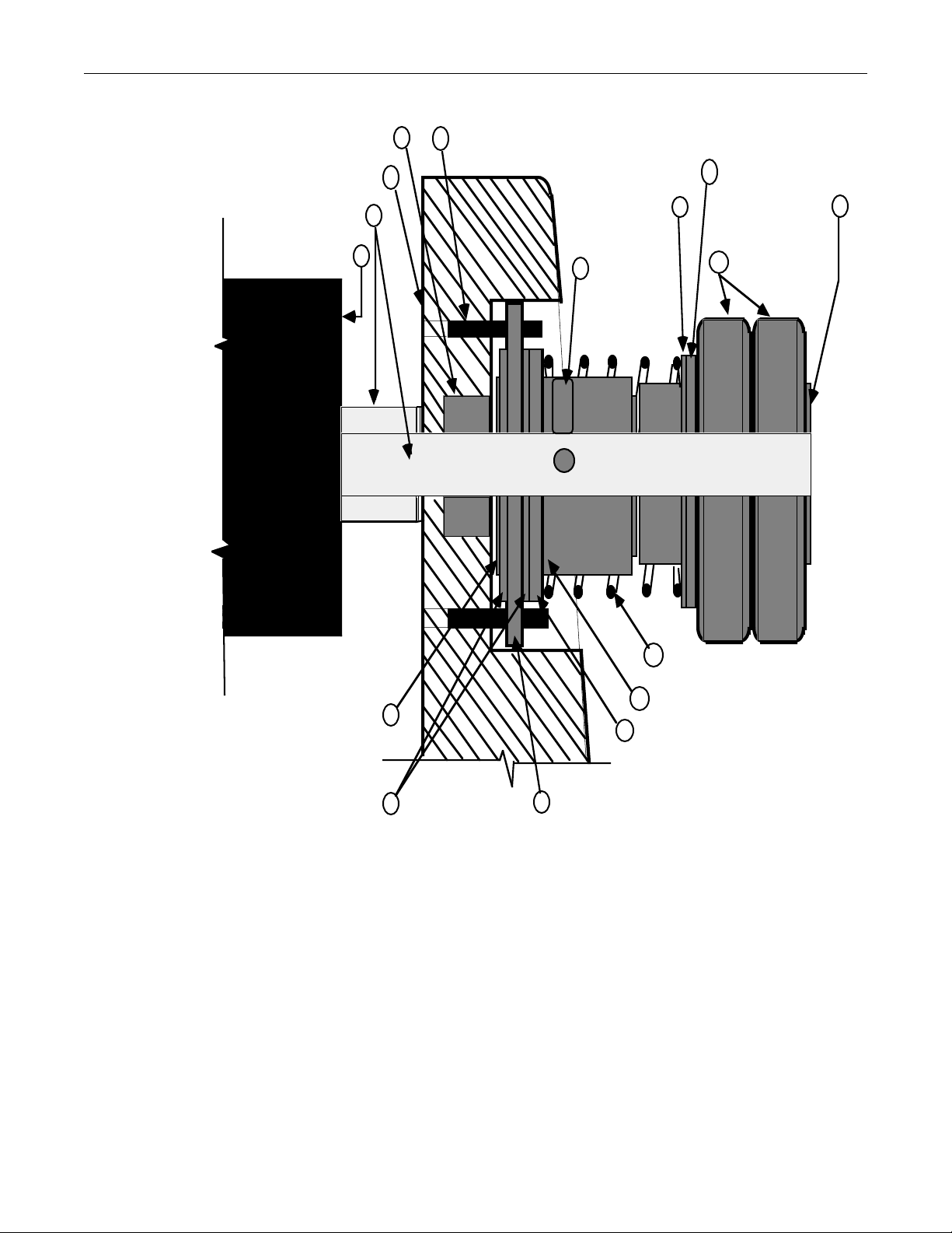
PantherPro/46 Image Recorder TP8251
Ball Bearing
Image Recorder Base
Drag Roller Shaft
Drag Roller (rubber) 12
13
14
15
Clutch Mounting Pins (3)
16
Neoprene Washer
Cup Point
5
Set Screw (2)
Washer
10
8
Clutch Adapter Shaft
Knurled Hand Nut
9
11
7
Compression
Spring
6
Clutch Collet
1
Teflon Flat Washer
2
3
Clutch Plate
NeopreneWasher
4
Stainless Steel
Washer
Adjustable Clutch (mounted cross section)
Figure 7-5
Note: Item 8 in Figure 7-5 is not required.
7-23 Drag Roller
Step 1. Remove the drag roller clutch. Refer to 7-22.
Step 2. Remove the two pan head screws that secure the drag roller bearing to the base
casting.
Step 3. Remove the roller bearing, spring washer, and drag roller.
October 1995 PrePRESS SOLUTIONS CONFIDENTIAL 7-17
Page 79

TP8251 PantherPro/46 Image Recorder
Step 4. Replace drag roller in reverse order of removal.
7-24 Drive Roller
Note: Removal of the drive roller or drive roller left bearing requires the front panel and
main bulkhead to be removed.
Step 1. Remove the front panel. Refer to step 7-1.C.
Step 2. Remove the main bulkhead.
Step 3. Remove the rear access panel. Refer to 7-1.
Step 4. Loosen the spur gear clamp and remove the spur gear from the right side of the
drive roller shaft.
Step 5. Remove two pan head screws, bearing, flat washer, and spring washer from the
right side of the drive roller shaft.
Step 6. Remove the two pan head screws, bearing, and flat washer from the left side of
the drive roller shaft.
Step 7. Remove the drive roller.
Step 8. Replace drive roller in reverse order of removal.
7-25 Knife Motor Assembly
Step 1. Open the take-up cassette and supply cassette doors.
Step 2. Remove the rear access cover. Refer to 7-1.
Step 3. Disconnect the knife motor cable from the main harness.
Step 4. Slide the knife carriage to the left side of the lead screw.
I.
I.
Step 5. Loosen the two set screws which secure the lead screw to the knife motor shaft.
Step 6. Remove the three (or four) knife motor mounting screws. Note the location of the
screws if only three mounting screws are used.
Step 7. Pull apart the knife motor shaft from the knife carriage lead screw.
Step 8. Remove the knife motor.
Step 9. Replace knife motor in reverse order of removal. Note that one of the worm shaft
set screws is secured to the flat of the knife motor shaft.
7-18 PrePRESS SOLUTIONS CONFIDENTIAL October 1995
Page 80

PantherPro/46 Image Recorder TP8251
7-26 Knife Carriage Assembly
Step 1. Remove the knife motor assembly. Refer to 7-25.
Step 2. Pull lead screw out of bronze bushing and rotate lead screw counter clockwise to
remove knife carriage assembly.
Note: Be careful not to damage lead screw.
Step 3. Replace knife carriage assembly in reverse order of removal.
Step 4. Verify the rotary knife assembly is positioned properly against the stationary knife
and pressure plate. Manually test knife carriage movement.
7-27 Worm Gearbox Assy.
Step 1. Remove the rear access panel/ Refer to 7-1.
Step 2. Disconnect leading motor and encoder cables.
Note: Observe encoder connector orientation before removing.
I.
Step 3. Remove the three large hex head screws which secure the gearbox and
groundwires to casting.
7-28 Leading Worm (Refer to Figure 7-7)
Step 1. Remove worm gear box assembly. Refer to 7-27.
Step 2. Loosen the coupling set screw on the worm side.
Step 3. Remove the worm gear by removing the "E" ring and washer from the motor side
of the worm, and the "E" ring, spring washer, two flat washers and bearing from
the other side.
Step 4. Replace the worm gear in reverse order of removal.
Step 5. Lubricate gear with grease (P/N 0923820)
October 1995 PrePRESS SOLUTIONS CONFIDENTIAL 7-19
Page 81

TP8251 PantherPro/46 Image Recorder
7-29 Servo Leading Motor/Encoder Assembly (Refer to Figure 7-7)
Note: The worm gear must be removed from gear box before the servo motor may be
removed.
Step 1. Remove worm gear box assembly. Refer to 7-28.
Step 2. Remove the coupling by loosening the set screws on the servo motor side.
Step 3. Remove the screws that mount the servo leading motor/encoder to the gearbox.
Step 4. Replace the servo leading motor/encoder in reverse order of removal.
7-30 Leading Spur Gear
Step 1. Remove the rear access panel. Refer to 7-1.
Step 2. Loosen the hex head screw on the spur gear clamp.
Step 3. Slide the spur gear off the roller shaft.
I.
Step 4. Replace the spur gear in reverse order of removal. Install spur gear with clamp
facing base casting.
Step 5. Lubricate spur gear with gear grease (P/N 09-23820).
7-20 PrePRESS SOLUTIONS CONFIDENTIAL October 1995
Page 82
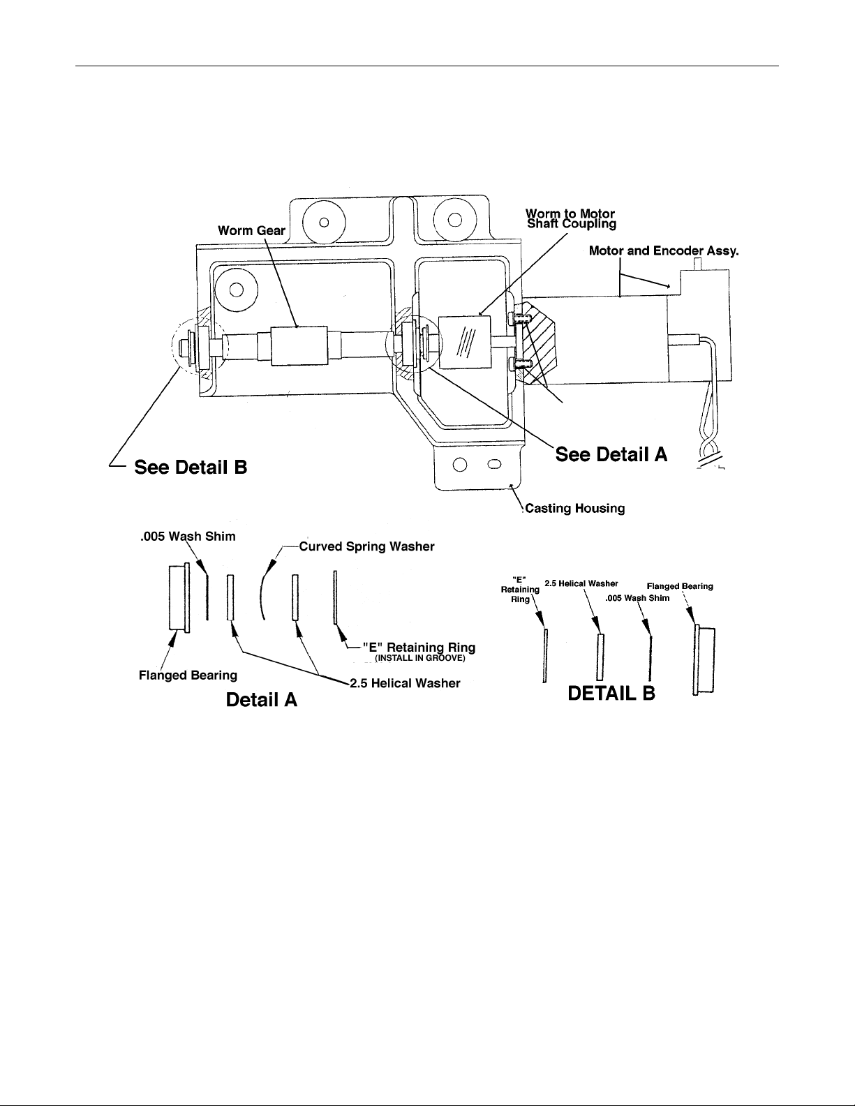
PantherPro/46 Image Recorder TP8251
Leading Motor and Worm
Figure 7-7
October 1995 PrePRESS SOLUTIONS CONFIDENTIAL 7-21
Page 83

PantherPro/46 Image Recorder TP8251
Section 8 Reference/Adjustments
DANGER - Visible red laser radiation is present when the optics cover or supply
cassette cover is open with the safety switch defeated. Avoid direct exposure to beam.
CAUTION - Use of controls or adjustments or performance of procedures other than
those specified herein may result in hazardous radiation exposure.
CAUTION: Remove recorder AC power cord before removing power supply from
electronic chassis.
NOTE - Maintain all anti-static procedures while performing removal/replacement
procedures on PC boards or electronics components.
8-1 PantherPro/46 Image Recorder Component Locations
8.1.1 Electronics Chassis
Components referred to in the electronics chassis are as follows:
• Big Output Board (BOB)/Wide Controller Board (WCB)
• Plug-in Page Buffer Module
• Page Buffer Disk Drive
• Zenith Power Supply
• Condor Power Supply
• Polygon Driver PCB
• Fuses
8.1.2 Optics Area
Components referred to which are located in the optics area are as follows:
• High Speed Laser Amplifier PCB
• High Speed Laser Driver PCB
8.1.3 Media Transport Area
Components referred to in the media transport area are as follows:
• Take-up Cassette
• Supply Cassette
• Adjustable Clutch
8.1.4 Recorder Output Copy Adjustments
The recorder output copy adjustments are as follows:
• Line Length
• Leading
October 1995 PrePRESS SOLUTIONS CONFIDENTIAL 8-1
Page 84

TP8251 PantherPro/46 Image Recorder
• Margin
8-2 PCB (Jumpers, LED's, Switches, etc.) Reference/Adjustments
The following details the switch settings, LED's, and jumpers found on the PC boards.
8-2.1 Big Output Board/WCB
8-2.1.1 Recorder Output Module Section (ROPM)
The ROPM section of the BOB/WCB contains some switches and LEDs which are useful in
diagnosing errors. The switches and LEDs are described below, and a procedure is given for
using the switches. Also, the action of the LEDs during output of a normal image is described.
Switches
A 4-position dipswitch, SW4, is located on the right upper side of the BOB/WCB. These
switches should all be in the open position for normal operation. The purpose of each switch
position is explained as follows:
SW4
1 2 3 4
Note: The LEDs mentioned in this section (OK, LOCK, etc.) are described in the LEDs
section.
Switch 1 - PGEN - Sets Page Enable, allowing start pulses to be found. Provided the
polygon is up to speed (speed OK), the laser will do the normal functions of sample/hold and
enhance, finding start pulses. If the laser beam path is interrupted or blocked, (by a laser
power meter, for example) the laser enhance power is kept on, searching for a start pulse
(from SOL sensor). Once a start pulse signal is fed back to the BOB/WCB, via the SOL/SOL
Amplifier and High Speed Laser Amplifier PCB, the laser beam power level will switch to
sample/hold (imaging) mode.
This provides a simple means for checking or adjusting the "enhance" laser power level and
to determine if the SOL sensor generates the 'START' signal.
During normal operation, with polygon up to speed, the LOCK, OK, STOK, and VID LEDs will
be lit.
Switch 2 - SHOLD - Forces Sample/Hold on for laser power calibration. This switch forces
video 'ones' pixels to be output continuously by the laser. This provides a simple means of
checking or adjusting the 'imaging' laser power level. The laser intensity is set by
hexadecimal data (intensity register/exposure setting) sent to a digital to analog converter.
During normal operation, LOCK, OK, and VID LEDs will be lit.
8-2 PrePRESS SOLUTIONS CONFIDENTIAL October 1995
Page 85

PantherPro/46 Image Recorder TP8251
Switch 3 - POLYSW - Brings polygon up to speed independent of software, using only
hardware generated signals. During normal operation, the polygon will not spin up until the
main application program is loaded. Lock and OK LEDs should be lit.
Switch 4 - POLYTYPE - Tells software polygon type (on for Lincoln type, off for Copal). Not
currently implemented. At present (5/15/95), only Lincoln type polygon motors assemblies
have been used in the PantherPro/46/36.
LEDs
Ten LEDs in two groups are associated with the Recorder Output Module. They are located
on the top left of the board with a silk-screened name above each. One group of 8 green
LEDs are for status, and two red LEDs (POLY ERR, FIFO MT) indicate an error condition.
Each of these LEDs are described as follows:
LOCK Indicates Polygon Driver PCB has locked the polygon speed. This should
always be lit (within 35 seconds) when the polygon is spun up.
LO The next three LEDs indicate polygon speed is low, ok, or high. They are
OK updated every scan line, and, when the polygon is spun up, OK should be
lit
HI and LO and HI never lit.
STOK Start pulses are being found by the SOL/SOL Amplifier assembly and fed
back to the BOB/WCB via the High Sped Laser Amplifier PCB.
VMWR Indicates video writes into the Dual Ported Video Memory from the
compression chip. This LED is not brightly lit.
VMWR Indicates video reads from the Dual Ported Video Memory to the ScanLine
FIFO. This LED is not brightly lit.
VID Indicates actual Video data. This LED is lit during the exposed parts of an
image (laser on). Note the sample/hold and enhance video activity light is
dimly it even during an all white image (laser off).
POLY ERR Indicates a Polygon Error condition. This happens only during imaging (Page
Enable on); the LED is kept on until the start of the next image. This error is
caused by loss of SPEED OK, however briefly, during an image. The loss of
LOCK is not monitored if a no (speed) lock PAL is installed.
FIFO MT Indicates a FIFO Empty Error condition. This happens only during imaging
(Page Enable ON); the LED is kept on until the start of the next image. This
error is caused when a video read from the Scan Line FIFO is attempted and
the FIFO is already empty.
Switches and LEDs Used for a Quick Check of Polygon and Laser
1. Put the 4 switches (PGEN, SHOLD, POLYSW, and POLYTYPE) of dip switch
SW4 to the open position.
October 1995 PrePRESS SOLUTIONS CONFIDENTIAL 8-3
Page 86

TP8251 PantherPro/46 Image Recorder
2. Power up the BOB/WCB.
3. The LO LED should be the only one (of the above LEDs) lit.
4. Put the POLYSW switch to the closed position.
5. The polygon will spin up. It should take approximately 30 seconds from a dead
stop. The LOCK, LO, OK, and HI LEDs may wink around for a second as the
polygon comes up to speed. Then LOCK and OK should be lit steadily.
If LOCK LED is not lit, the polygon, polygon driver, or +24 volt (Condor power
supply) may be defective.
If LOCK LED is lit, but OK is not, the polygon INDEX signal, cabling, or Big Output
Board/WCB may be defective.
6. Put the PGEN switch to the closed position.
7. The STOK LED will light immediately. If STOK is not lit, check high speed laser
amplifier, laser diode assembly (and enhance signal), cabling, and supply cassette
door. If laser is on, check start signal at the high speed laser amplifier board. If
'START' signal is present, possible defective Big Output Board/WCB.
Action of LEDs During Normal Image
The purpose of the LEDs is to aid in debug. The following is a description of the LEDs during
normal recorder operation:
1. At first, only the LOCK and OK LEDs should be lit. If they are not lit, check
polygon, polygon driver board, +24 volt Condor power supply, and cabling.
2. The VMWR LED comes on briefly. This happens as the Dual Ported Video
Memory is filled with video data. When it is filled:
3. The STOK LED comes on. Start pulses are being found and the image is being
output. At the same time, the VMWR LED may drop in intensity and the VMRD LED
comes on. These are both rather dim; their brightness depends on the rate of
reading/writing to the DPVM. (The VMRD LED shows that video is being read out of
the DPVM) The VID LED at this time will come on and vary with image data.
4. Just before the end of an image, the VMWR LED will go off, because all the video
data has been written into the DPVM.
5. A fraction of a second later, the VMRD LED will go off, because all the video data
has now been read from the DPVM. At the same time, the STOK and VID LEDs will
go off. The image is completed.
6. At no time should the POLYERR or FIFO MT LEDs come on. The POLY ERR
would most likely indicate a problem with the polygon, polygon driver board, or
cabling. The FIFO MT LED is a little more tricky; it indicates any type of problem in
the real-time flow of data between the Page Buffer disk drive and BOB/WCB.
8-4 PrePRESS SOLUTIONS CONFIDENTIAL October 1995
Page 87
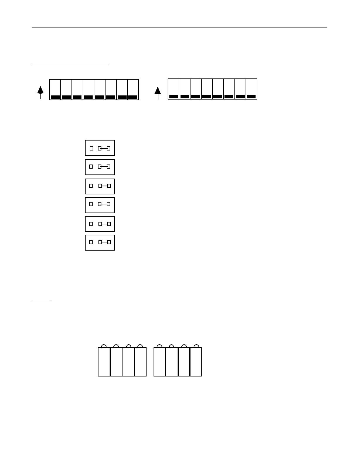
PantherPro/46 Image Recorder TP8251
8-2.1.2 Page Buffer Module Section
Switches and Jumpers
ONON
SW1
All switches on SW1 and SW2 are in "OFF" position for normal operation.
SW2
PBM BOB/WCB Jumpers
JP100JP27
JP101JP28
JP102JP29
JP103JP30
JP104JP31
JP105JP32
Note: Etch jumpers JP110 through JP125 are cut on each plug-in PBM.
Note: Etch jumpers JP11 through JP26 are cut on the BOB/WCB PBM.
LEDs
On the BOB/WCB, the LEDs are D11 and D12. On the Page Buffer Module, the LEDs are D12
and D13. The meaning of each LED when "ON" is described below.
1234 6 857
D11: BOB/WCB
D12: PBM
1 - HGNT - The HOST SIOP is a 68000 bus master.
2 - DGNT - The DISK SIOP is a 68000 bus Master.
October 1995 PrePRESS SOLUTIONS CONFIDENTIAL 8-5
D12: BOB/WCB
D13: PBM
Page 88

TP8251 PantherPro/46 Image Recorder
3 - IMG - The Page Buffer Module is selected to image.
4 - DMEM - The local Page Buffer Module DRAM is being accessed.
5 - CPRS - The PBM is selected to accept input data (compression path
enabled).
6 - BXCV - Data moving from port A of the 3210 to local DRAM (compression mode) or
data is moving from the DISK SIOP to port B of the 3210
(decompression mode).
7 - DA - Video data is being moved into Port A (compression) or video data is being output
(decompression).
8 - DB - Video data is being moved into local DRAM (compression) or compressed data is
being sent to the 3210 (decompression).
8-2.2 Polygon Driver Board
All I/O signals are via connector J3 on the polygon driver PCB:
/ENABLE - The polygon motor will rotate when a logic low signal is applied to /ENABLE.
SYNC - This output goes low when the polygon scanner is within 1% of the correct operating
speed. The LOCK LED will be lit at this time.
/INDEX - This output provides one pulse every shaft rotation of the polygon scanner, which is
fed back to the BOB/WCB ROPM module. The speed OK LED will be lit if the polygon speed
is stable within a specific range dictated by software.
NOTE: After the INDEX signal is detected by the BOB/WCB, the SOL START signal is
used to monitor polygon scanner speed. This process is repeated for each polygon
revolution during imaging (Page Enable).
EXT. FR. IN - This input signal is provided by the BOB/WCB ROPM module, and is necessary
to operate and lock polygon scanner at a specific speed.
Jumpers
JB1 - TEST/RUN Jumper
For (standard) normal operation, JB1 should be strapped as displayed below.
JB1
Test B Run
LEDs
LED (green), indicates presence of DC voltage at the Polygon Driver Board.
The +24 volts test point is located at the top right of the BOB/WCB.
8-6 PrePRESS SOLUTIONS CONFIDENTIAL October 1995
Page 89
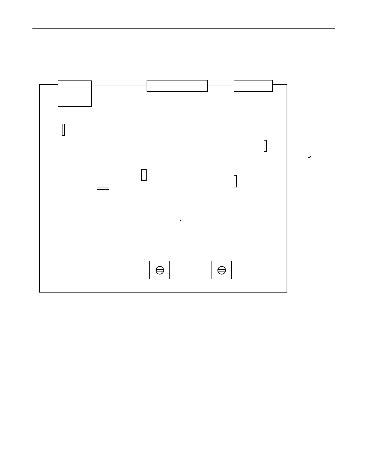
PantherPro/46 Image Recorder TP8251
8-2.3 High Speed Laser Amplifier Adjustments/Calibration
High Speed Laser Amplifier Reference and Offset Measurement/Calibration Procedure:
J1
GDN TP1
TP1
J2
High Speed Laser Amplifier PCB
JP1
R22 R28
J3
GND TP2
TP2
7.5 ADJUST
Note: All replacement High Speed Laser amplifier PCBs are factory tested and
calibrated. Perform the calibration procedure only if laser diode power or HSLA PCB
performance is suspect.
Step 1. Make sure recorder power is "OFF".
Step 2. Disconnect J3 (J1 and J2 remain connected) and jumper JP1.
Step 3. Attach Voltmeter between TP1 and GND TP1 and turn recorder power "ON".
Step 4. Adjust R22 until a reading of 7.5 volts is achieved.
Step 5. Turn recorder power "OFF".
Step 6. Attach volt meter to TP2 and GND TP2.
October 1995 PrePRESS SOLUTIONS CONFIDENTIAL 8-7
OFFSET ADJUST
Page 90

TP8251 PantherPro/46 Image Recorder
Step 7. On BOB/WCB at SW4, set switch 2 (SHOLD) "ON".
Step 8. Turn recorder power "ON".
Step 9. Adjust R28 until a reading of 0.0 volts is achieved.
Step 10. Turn recorder power "OFF". Reinstall JP1 and connector in J3.
8-2.4 High Speed Laser Driver/Tube Assembly
The laser THRESHOLD, EFFICIENCY, and ENHANCE power is calibrated using three
potentiometers, R9, R1, and R5, which are located on the High Speed Laser Driver PCB.
These potentiometers are used in conjunction with the ROPM switch SW4 (located on the
BOB/WCB) and a laser power meter, while executing the Laser System Calibration
diagnostic test. The Laser Power Calibration Utility is contained in the Recorder Utilities
found in the Recorder Output Module Diagnostics.
The Laser Power Calibration Utility is primarily used in the field as a debug tool to measure
and/or calibrate the laser output power. For example, if two PatherPro/46's are used under
the same environment, and conditions (media, processor chemistry, etc.), the exposure value
settings of each recorder should be set similarly.
High Speed Laser Driver PCB Potentiometer Description:
R5
R1
R9
R9 - This potentiometer is used to set the laser Threshold power.
R1 - This potentiometer is used to set the laser Efficiency power.
R5 - This potentiometer is used to set the laser Enhance power.
The PantherPro/46/36 Laser Power Measurement/Adjustment Procedure:
Precautions:
• Follow all laser safety measures.
• Be aware of shiny objects that may reflect laser light, such as laser power meter,
jewelry, etc.
Equipment Required:
• Known good High Speed Laser Amplifier
• Some form of laser power meter
• Insulated potentiometer tweeker or small blade screw driver
8-8 PrePRESS SOLUTIONS CONFIDENTIAL October 1995
Page 91

PantherPro/46 Image Recorder TP8251
Adjustment Procedure:
Note: As a reminder, the laser power should be measured before any adjustments are
performed. All replacement laser diode assemblies (and laser amplifier PCBs) are
factory tested and calibrated. If potentiometer R1, R5, or R9 is adjusted, the laser power
calibration tests must be performed and rechecked.
Step 1. Power down the recorder.
Step 2. Turn the recorder power "On".
Step 3. Set SW4 switch 2 and 3 to "ON" position. SW4 is located on the BOB/WCB.
Step 4. Abort the start-up by pressing the "On-line" key when prompted (after the Level 2
diagnostics).
Step 5. Select F2 to enter the Disk Based Utilities.
Step 6. Select F1 to enter the Recorder OutPut Module Diagnostics.
Step 7. Select F3 to enter the Recorder Utilities.
Step 8. Place the laser meter/wand in a non-perpendicular fashion directly in front of the
laser tube, between the laser tube and mask. Position it to obtain the maximum
laser power reading. Ambient light may affect laser power measurement.
Step 9. Scroll to page 2 and execute the Laser Power Calibration Test. Follow the
instructions displayed on the recorder front panel. Refer to the laser power values
below. The Laser Calibration Test is interactive and will prompt you to check the
laser power Threshold, Efficiency, and Enhance modes. Keep in mind the
Threshold and Efficiency measurement/calibration requires SW4 switch 2 and 3
to be set "On". When performing the Enhance mode measurement/calibration,
turn "OFF" switch 2 and turn "ON" switch 1 and 3.)
Laser power values:
• Threshold mode reading set to 3.2mv (or 123uW).
• Efficiency mode reading set to 28mv (or 1076uW).
• Enhance Mode reading set to 65mv (or 2500uW)
Note: 38.46uW/mV
8-3 Page Buffer Disk Drive Jumpers
October 1995 PrePRESS SOLUTIONS CONFIDENTIAL 8-9
Page 92

TP8251 PantherPro/46 Image Recorder
Jumpers
Digital Equipment Corporation (DEC) Series Jumper Settings are as follows:
Termination
Header
SCSI Power
SCSI address ID is set to 0 (no jumper) on all Page Buffer drives. The only jumpers required
are shown above to provide termination power to the SCSI bus and active termination
enabled.
8-4 Power Supply Jumpers/Adjustments
8-10 PrePRESS SOLUTIONS CONFIDENTIAL October 1995
Page 93
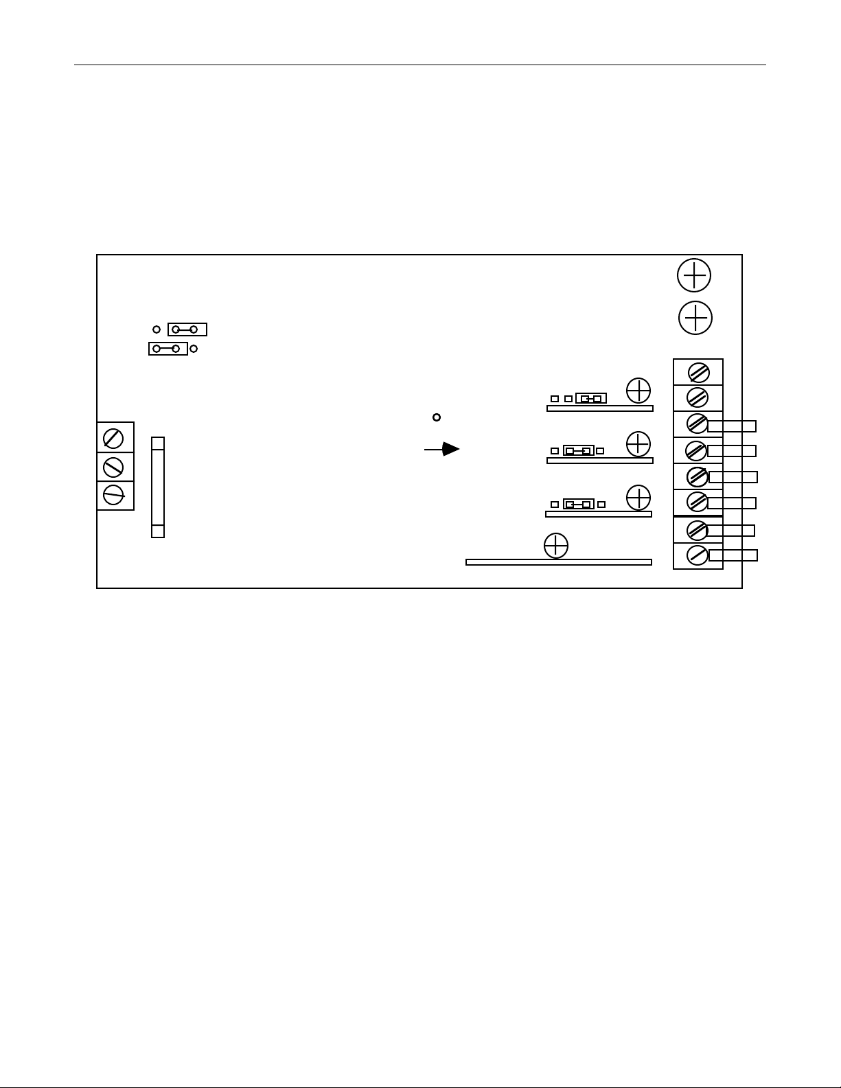
PantherPro/46 Image Recorder TP8251
(
)
8-4.1 Zenith ZPS-300A Power Supply (Refer to Figure 8-1)
The Zenith ZPS-300A supplies +5,+12, +12, and -12 volts.
AC Input Jumper
SWX2
230V
115V
AC Input
TB1
1
PB Drive +12v Voltage
2
Fuse
10 Amp
3
(measure at PB drive)
+5v
channel 1
TB2 DC Output Connections
TB2-3 +12V BOB/WCB (GRY)
TB2-4 +12V Return BOB/WCB (BLK)
TB2-5 +12V PB Drives (GRY) & Optics Fan (RED)
TB2-6 +12V RTN PB Drives & Optics Fans (BLK)
TB2-7 -12V RTN BOB/WCB & Fans, (BLK)
TB2-8 -12V BOB/WCB & Fans
BLU
+12v
channel 2
+12v
channel 3
-12v
channel 4
+5V
RTN
TB2
1
2
3
4
5
6
7
8
Zenith ZPS-300 Power Supply
Figure 8-1
8-4.2 Condor Power Supply (Refer to Figure 8-2)
October 1995 PrePRESS SOLUTIONS CONFIDENTIAL 8-11
Page 94

TP8251 PantherPro/46 Image Recorder
The Condor Power Supply supplies +24 volts to polygon driver board.
7
6
-OUT -S
P2 (+24VDC)
Input
120VAC
-S +OUT
Transformer Terminals
Jumper
1-3, 2-4
+24VAdj.
To TB-2
Zenith ZPS-300
To TB-1
Fuse
Rating
2 amp
Transformer
Terminals
BLU
BRN
5
1
3
2
4
FUSE
240VAC
8-5 Take-up Cassette (Refer To Figure 8-3 on the next page)
8-12 PrePRESS SOLUTIONS CONFIDENTIAL October 1995
2-3
1 amp
Condor Power Supply
Figure 8-2
Page 95

PantherPro/46 Image Recorder TP8251
Note: The latest take-up cassette changes include:
• Rubber Bumpers (under take-up cassette handle)
• Taller door light shielding gasket
• New shaft to accomodate the center hub E-clips and 15" cassettes.
• For 18" and 16" take-up cassettes only - center hub, center hub disks,
E-clips
• Less springs for 18" and 16" cassettes (Refer to configuration drawing
Figure 8-3)
8-6 Supply Cassette
Note: The latest supply casette changes include:
• New shaft - to center the media with the pin registration punch system and
take-up cassette.
• Removal of the spacer/washer located between the thumb screw and
left hub to center the media with the pin registration punch system and take-up
cassette.
• Anti-slip tape and hold down clip. (Note: Hold down clip supject to
change. Check with Support Services.)
8-6.1 Shaft Positioning
The supply cassette shaft is positioned in the supply cassette between the (left) set screw and
the (right) ball plunger screw.
The left set screw is used to offset the shaft position to keep the shaft left end from digging
into the cassette plastic housing. Adjusting the left set screw will also change the margin
width and the punch hole to media position. Do not allow the left set screw to offset shaft
more than .002".
The right ball plunger screw is used to push and hold the shaft against the left set screw. The
spring loaded ball plunger tip should be compressed slightly to ensure stable shaft position.
The supply cassette may be configured for different media widths. Refer to the PantherPro/46
User's Guide for configuration information.
8-6.2 Anti-slip Tape and Hold Down Clip Installation (Refer to Figure 8-4)
General Overview
The PantherPro/46 image recorders shipped prior to October, 1994 may require installation
of anti-slip/stick tape at the point of contact between the media shaft and the supply cassette
(pedestal). The installation of the tape would be necessary only if there are banding artifacts,
most noticable at the fist inch or so of an image.
An anti-slip tape hold down clip has also been released to secure the tape to the supply
cassette pedestal.
October 1995 PrePRESS SOLUTIONS CONFIDENTIAL 8-13
Page 96
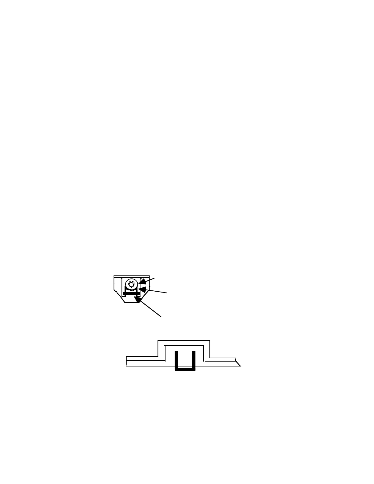
TP8251 PantherPro/46 Image Recorder
Hardware Issues
A one piece of anti-slip/stick tape 3/4" wide and 3/4" long is provided by ordering P/N 285-
009848000. One piece of tape should be sufficient, unless you experience difficulty installing
the tape. It is advisable to order a quantity of 2.
The hold down clip P/N is 201010384000. Order a qty. of 2 per supply cassette.
Installation Instructions
No special tools are required to install the tape or the hold down clip. A thin instrument such
as exacta knife or small flat screw driver is recommended to install the anti-slip tape.
Step 1. From a single piece of tape, cut two pieces 3/8" wide and 3/4" long.
Step 2. Open the supply cassette and remove the media shaft.
Step 3. Peal the protective film from the back of the tape.
Step 4. The sticky tape covers the cassette pedestal on which the media shaft rests.
Refer to Figure 8-3. Place one piece of tape on the right pedestal and one piece
on the left pedestal.
Step 5. From the inside of cassette, slide the hold down clip over and across the tape.
The hold down clip should be pushed in until tight and secure tape against the
pedastal. Note the position of the hold down clip at the base of the pedestal.
position of shaft resting
on pedastal
sticky tape
hold down clip
Hold Down Clip-Top View
Figure 8-4
8-7 Clutch
Refer to Section 6 for tension adjustment procedure.
8-14 PrePRESS SOLUTIONS CONFIDENTIAL October 1995
Page 97

PantherPro/46 Image Recorder TP8251
8-8 Line Length and Leading Adjustment
The line length and leading on the output copy from the PantherPro/46 image recorder is
adjusted by changing the line length and leading values that are stored in non-volatile RAM
on the BOB/WCB.
The line length value affects the speed of the polygon motor; as the polygon motor slows
down the line length decreases, and as the polygon motor speeds up the line length
increases. If the line length is too long, a negative value must be entered. If the line length is
too short, a positive value must be entered.
The leading value affects the speed of the servo leading motor; as the leading motor slows
down the leading decreases, and as the leading motor speeds up the leading increases.
Similar to setting the line length, a negative value is entered if the leading is too long and a
positive value is entered if it is too short.
Each one number increase or decrease in the line length or leading value represents a
change of approximately 0.001 inches on the copy. The line length and leading value can be
changed via the remote or local keypad of the recorder. The line length and leading value is
recorded in the electronics chassis.
Note: If having difficulty setting line length and leading values, perform the following:
1. Set line length and leading values to zero.
2. Reimage and measure line length and leading test copy.
3. Enter actual offset value.
The following key sequence is used to access and enter the line length and leading values
stored in the image recorder non-volatile RAM:
Step 1. Turn the recorder on and allow the main application program stored on Page
Buffer drive 0 to execute.
Step 2. Place the recorder "OFF-LINE" by pressing the "ON-LINE" (horseshoe) key.
Step 3. Locate the margin icon. Refer to the PantherPro/46 User's Guide if necessary.
Step 4. Press the "." key followed by the "+/-" key. This key sequence (., +/-) will be
referred to as "magic keys".
Note: If the magic keys are depressed when the line length and leading icons are
displayed, non-volatile RAM will be reset, thus returning all recorder values such as line
length, leading, exposure, etc. to recorder default values.
Step 5. The current line length and leading values will be displayed under their
respective icons. Change the values accordingly using the numeric key pad. Be
sure to depress the left arrow key to store each completed entry.
8-9 Margin Adjustment
The margin on the output copy from the PantherPro/46 recorder is adjusted by changing the
margin values that are stored in non-volatile RAM.
October 1995 PrePRESS SOLUTIONS CONFIDENTIAL 8-15
Page 98

TP8251 PantherPro/46 Image Recorder
The margin values are changed using the local or remote keypad on the image recorder.
This procedure is explained in the PantherPro/46 User's Guide. The "magic key" sequence is
not necessary.
Note: Moving the supply cassette shaft reference screw or SOL sensor will affect the
margin setting.
8-16 PrePRESS SOLUTIONS CONFIDENTIAL October 1995
Page 99

PantherPro/46 Image Recorder TP8251
Section 9 Diagnostics
Introduction
Before discussing the PantherPro/46/36 Diagnostics, it will be beneficial to read the following
PantherPro Software Overview. Understanding how the PantherPro software is structured
will allow the technician to better utilize the Debug Port and its features. One important
debugging feature of the Debug Port is the ability to enter the Debug Bit Editor. Setting
certain debug bits will provide useful information about bomb messages, errors, and the
general operation of the recorder to aid in the debugging process.
9-1 PantherPro Software Overview
The PantherPro software is stored on Page Buffer drive 0, which is connected to the
BOB/WCB built-in page buffer module. (Refer to the PantherPro/46 User's Guide for
information on loading software and executing SCSI downloader.) The PantherPro
Downloader diskette contains the PantherPro Main Application program, Recorder Output
Module diagnostic program (ropmdiag), and the Controller diagnostic program (wcb_diag).
9-1.1 Main Application (Processes and Driver Modules)
The main application software is divided into many modules of two different types called
Processes and Drivers. Drivers do things in real time using interrupts from the hardware. A
Process is where most of the work that doesn't have to be done in real time takes place.
Root Process
This process is the first one started and does most of the general system initialization.
Plate Process and Driver
This process deals with making plates while the driver sends an receives messages to the
Plate Maker. The Plate Process and Driver also communicates with the Engine Process.
Target Driver
This driver uses the Host SCSI (HSIOP) side of a page buffer module to communicate to the
front end system and the Input Process.
SCSI Driver
This driver uses the Disk (DSIOP) side of the page buffer module to communicate to the Page
Buffer Disk Drives.
Input Process
This is the "heart" of the recorder that talks to the front end system for image buffering and
other communication.
Engine Process and Driver
The Engine refers to the actual imaging and leading hardware. This includes the cutter,
punch, polygon, and on-line processor. The Driver handles scanline interrupts and other real
time events with the leading while the Process sets it all up and monitors status once per
second. The Engine driver also handles the Smart Memory interface.
Panel Process and Driver
October 1995 PrePRESS SOLUTIONS CONFIDENTIAL 9-1
Page 100

TP8251 PantherPro/46 Image Recorder
The Panel Driver deals with the LCD display and the keypad. The Process is responsible for
formatting and displaying the LCD/Keypad status and operating the menu interface system.
The PantherPro/46 contains ROM resident diagnostics and disk resident diagnostics that can
be accessed both onsite and remotely through the debug port. Many of these diagnostics can
also be accessed through the keypad.
9-1.2 The Debug Port
The Debug Port is the source of all information in the PantherPro/46. It will provide more
information about bombs as well as general information about the operation of the recorder.
To use the Debug Port, a terminal or a terminal emulation program (ANSI/VT-100) must be
connected to the debug port. The default port parameters are 9600, N, 8, 1. Refer to the
MicroPhone terminal emulation program set-up procedure below.
Microphone Setup (Macintosh)
1. Launch the "Microphone" utility program. This is a communication program.
2. Select the communication menu option in the settings window.
3. Select the following parameters in this window.
Baud Rate: 19,200 (9600) for Panther or PantherPlus
Data Bits: 8
Stop Bits: Auto
Parity: None
Port: Printer
NOTE: The baud rate and port may need to be altered if communication is not
established. Verify that a debug cable is connected from the BOB/WCB debug port
on the recorder to the printer port on the Software RIP.
4. Select the terminal menu option in the settings window.
5. Select the following parameters in this window.
Terminal Type: VT102
VT102 Mode: ANSI
Columns: 88
Font Size: 9
Cursor Shape: Block
Backspace Key: Backspace
6. Type ^ U to reset the recorder
Refer to the Section 9-2 for additional information on how to run diagnostics.
9-1.3 Debug Bits
9-2 PrePRESS SOLUTIONS CONFIDENTIAL October 1995
 Loading...