

Page 1

PantherPro Image Recorder TP 8250
Table of Contents
Section 1 General Service Information Page
1-1 Scope of Manual . . . . . . . . . . . . . . . . . . . . . . . . . . . . . . . . . . . . . . . . . . 1-1
1-2 Laser Information . . . . . . . . . . . . . . . . . . . . . . . . . . . . . . . . . . . . . . . . . . 1-2
1-3 Regulatory Agencies Information. . . . . . . . . . . . . . . . . . . . . . . . . . . . . . 1-4
1-4 Electrostatic Discharge - ESD . . . . . . . . . . . . . . . . . . . . . . . . . . . . . . . . 1-4
Section 2 Overview and Specifications
2-1 Product Overview. . . . . . . . . . . . . . . . . . . . . . . . . . . . . . . . . . . . . . . . . . 2-1
2-2 Hardware Overview . . . . . . . . . . . . . . . . . . . . . . . . . . . . . . . . . . . . . . . . 2-2
2-3 Electrical Power Requirements . . . . . . . . . . . . . . . . . . . . . . . . . . . . . . . 2-5
2-4 Product Specifications . . . . . . . . . . . . . . . . . . . . . . . . . . . . . . . . . . . . . . 2-6
Section 3 Theory of Operation
3-1 Panther Pro Overview . . . . . . . . . . . . . . . . . . . . . . . . . . . . . . . . . . . . . . 3-1
3-2 High Speed Control (HSCB) . . . . . . . . . . . . . . . . . . . . . . . . . . . . . . . . . 3-2
3-3 CPU and Peripherals Module Overview . . . . . . . . . . . . . . . . . . . . . . . . 3-2
3-4 Page Buffer Module Overview . . . . . . . . . . . . . . . . . . . . . . . . . . . . . . . . 3-4
3-5 Recorder Output Module Overview . . . . . . . . . . . . . . . . . . . . . . . . . . . . 3-5
3-6 Media Transport. . . . . . . . . . . . . . . . . . . . . . . . . . . . . . . . . . . . . . . . . . . 3-7
3-7 Optics. . . . . . . . . . . . . . . . . . . . . . . . . . . . . . . . . . . . . . . . . . . . . . . . . . . 3-9
Section 4 Power Supply and Distribution
4-1 AC Power. . . . . . . . . . . . . . . . . . . . . . . . . . . . . . . . . . . . . . . . . . . . . . . . 4-1
4-2 DC Power. . . . . . . . . . . . . . . . . . . . . . . . . . . . . . . . . . . . . . . . . . . . . . . . 4-3
Section 5 Installation
5-1 Bill of Materials. . . . . . . . . . . . . . . . . . . . . . . . . . . . . . . . . . . . . . . . . . . . 5-1
5-2 Pre-Installation Procedures . . . . . . . . . . . . . . . . . . . . . . . . . . . . . . . . . . 5-1
5-3 Electrical Requirements . . . . . . . . . . . . . . . . . . . . . . . . . . . . . . . . . . . . . 5-2
5-4 Installation Procedures . . . . . . . . . . . . . . . . . . . . . . . . . . . . . . . . . . . . . 5-2
5-5 System Test . . . . . . . . . . . . . . . . . . . . . . . . . . . . . . . . . . . . . . . . . . . . . . 5-3
5-6 Installation Completion. . . . . . . . . . . . . . . . . . . . . . . . . . . . . . . . . . . . . . 5-3
PrePRESS SOLUTIONS
i June 1994
Page 2

TP 8250
Section 6 Removal/Replacement Page
6-1 External Covers and Panels . . . . . . . . . . . . . . . . . . . . . . . . . . . . . . . . . 6-1
6-2 E. M. I. Shield. . . . . . . . . . . . . . . . . . . . . . . . . . . . . . . . . . . . . . . . . . . . . 6-4
6-3 Keypad/LCD Assembly . . . . . . . . . . . . . . . . . . . . . . . . . . . . . . . . . . . . . 6-5
6-4 Electronics Assembly. . . . . . . . . . . . . . . . . . . . . . . . . . . . . . . . . . . . . . . 6-5
6-5 Fan Assembly . . . . . . . . . . . . . . . . . . . . . . . . . . . . . . . . . . . . . . . . . . . . 6-5
6-6 Power Supply. . . . . . . . . . . . . . . . . . . . . . . . . . . . . . . . . . . . . . . . . . . . . 6-5
6-7 I/O Panel Assembly . . . . . . . . . . . . . . . . . . . . . . . . . . . . . . . . . . . . . . . . 6-6
6-8 Polygon Motor Assembly . . . . . . . . . . . . . . . . . . . . . . . . . . . . . . . . . . . . 6-6
6-9 Laser Amplifier PCB. . . . . . . . . . . . . . . . . . . . . . . . . . . . . . . . . . . . . . . . 6-6
6-10 Polygon Driver PCB . . . . . . . . . . . . . . . . . . . . . . . . . . . . . . . . . . . . . . . . 6-6
6-11 Laser Diode Assembly . . . . . . . . . . . . . . . . . . . . . . . . . . . . . . . . . . . . . . 6-7
6-12 Second Cylinder Lens Assembly . . . . . . . . . . . . . . . . . . . . . . . . . . . . . . 6-8
6-13 Start Of Line Sensor PCB . . . . . . . . . . . . . . . . . . . . . . . . . . . . . . . . . . . 6-8
6-14 Paper Feed Gate Assembly. . . . . . . . . . . . . . . . . . . . . . . . . . . . . . . . . . 6-9
6-15 Gate Assembly Rollers . . . . . . . . . . . . . . . . . . . . . . . . . . . . . . . . . . . . 6-10
6-16 Metering Roller. . . . . . . . . . . . . . . . . . . . . . . . . . . . . . . . . . . . . . . . . . . 6-11
6-17 Drive Roller . . . . . . . . . . . . . . . . . . . . . . . . . . . . . . . . . . . . . . . . . . . . . 6-12
6-18 Knife Carriage Assembly . . . . . . . . . . . . . . . . . . . . . . . . . . . . . . . . . . . 6-13
6-19 Servo Leading Motor and Gearbox Assembly . . . . . . . . . . . . . . . . . . . 6-14
6-20 Servo Leading Motor . . . . . . . . . . . . . . . . . . . . . . . . . . . . . . . . . . . . . . 6-15
6-21 Leading Worm . . . . . . . . . . . . . . . . . . . . . . . . . . . . . . . . . . . . . . . . . . . 6-15
6-22 Leading Spur Gear. . . . . . . . . . . . . . . . . . . . . . . . . . . . . . . . . . . . . . . . 6-16
PantherPro Image Recorder
Section 7 Diagnostics
7-1 Overview . . . . . . . . . . . . . . . . . . . . . . . . . . . . . . . . . . . . . . . . . . . . . . . . 7-1
7-2 PROM Resident Diagnostics . . . . . . . . . . . . . . . . . . . . . . . . . . . . . . . . . 7-1
7-2.1 Level 1 Power-up Test . . . . . . . . . . . . . . . . . . . . . . . . . . . . . . . . . . . . . . 7-1
7-2.2 PROM Monitor . . . . . . . . . . . . . . . . . . . . . . . . . . . . . . . . . . . . . . . . . . . . 7-2
7-2.3 Level 2 Diagnostics . . . . . . . . . . . . . . . . . . . . . . . . . . . . . . . . . . . . . . . . 7-2
7-3 Disk Based Diagnostics . . . . . . . . . . . . . . . . . . . . . . . . . . . . . . . . . . . . . 7-4
7-3.1 HSCB_Diag . . . . . . . . . . . . . . . . . . . . . . . . . . . . . . . . . . . . . . . . . . . . . . 7-4
7-4 Keypad Diagnostics . . . . . . . . . . . . . . . . . . . . . . . . . . . . . . . . . . . . . . . . 7-7
7-4.1 Level 2 Tests . . . . . . . . . . . . . . . . . . . . . . . . . . . . . . . . . . . . . . . . . . . . . 7-7
7-4.2 Disk Based Utilities . . . . . . . . . . . . . . . . . . . . . . . . . . . . . . . . . . . . . . . . 7-8
7-4.3 Communications Utilities . . . . . . . . . . . . . . . . . . . . . . . . . . . . . . . . . . . . 7-9
7-4.4 SCSI Downloader Utilities . . . . . . . . . . . . . . . . . . . . . . . . . . . . . . . . . . 7-10
Section 8 Reference/Adjustments
8-1 Jumpers, LED’s, and Switches . . . . . . . . . . . . . . . . . . . . . . . . . . . . . . . 8-1
8-2 Laser Amp 7.5V reference Adjustment . . . . . . . . . . . . . . . . . . . . . . . . . 8-4
8-3 Laser Amp Offset Adjustment . . . . . . . . . . . . . . . . . . . . . . . . . . . . . . . . 8-5
ii June 1994
PrePRESS SOLUTIONS
Page 3

PantherPro Image Recorder TP 8250
Section 9 PantherPro Parts Listing
Group 1 Case and Covers Front View . . . . . . . . . . . . . . . . . . . . . . . . . . . . . . . 9-2,3
Group 1A Case and Covers Rear View - I/O Panel . . . . . . . . . . . . . . . . . . . . . . 9-4,5
Group 2 Front Components . . . . . . . . . . . . . . . . . . . . . . . . . . . . . . . . . . . . . . . 9-6,7
Group 3 Optics, Laser Diode/Amp, Polygon . . . . . . . . . . . . . . . . . . . . . . . . . . 9-8,9
Group 4, 4A Paper Feed Transport . . . . . . . . . . . . . . . . . . . . . . . . . . . . . . . . . . 9-10,14
Group 4B Paper Feed Drive. . . . . . . . . . . . . . . . . . . . . . . . . . . . . . . . . . . . . . 9-14, 15
Group 5 Power Supply Drawer . . . . . . . . . . . . . . . . . . . . . . . . . . . . . . . . . . 9-16, 17
Group 6 Card Cage (PCB'S) . . . . . . . . . . . . . . . . . . . . . . . . . . . . . . . . . . . . 9-18, 19
Group 7 Take-Up Cassettes . . . . . . . . . . . . . . . . . . . . . . . . . . . . . . . . . . . . 9-20, 21
Group 8 Supply Cassettes, ETM Assembly. . . . . . . . . . . . . . . . . . . . . . . . . 9-22, 23
PrePRESS SOLUTIONS
iii June 1994
Page 4

TP 8250
PantherPro Image Recorder
iv June 1994
PrePRESS SOLUTIONS
Page 5

PantherPro Image Recorder TP 8250
PantherPro
IMAGESETTER
TECHNICAL MANUAL
TP 8250
2
November 1994
PrePRESS SOLUTIONS CONFIDENTIAL
PrePRESS SOLUTIONS
v June 1994
Page 6

PantherPro Image Recorder TP 8250
Section 1 General Service Information
1-1 Scope of Manual
The Model PantherPro Image Recorder Service Manual is intended for the use of trained
technical representatives of PrePRESS SOLUTIONS, its subsidiaries and dealers. It is not
intended as a substitute for training. Service personnel will utilize this document as a resource for information concerning the following aspects of effective service:
Section 1. “General Service Information”, contains general information regarding the
service manual, laser safety information, regulatory agencies information, and
electro static discharge prevention rules.
Section 2. “Overview and Specifications”, describes the features of the PantherPro and
products specifications.
Section 3. “Theory of Operation”, describes in detail the functionality of the PantherPro.
Section 4. “Power Supply and Distribution”, contains details regarding the DC and AC
power used on the PantherPro.
Section 5. “Installation”, contains the installation instructions for the PantherPro.
Section 6. “Removal/Replacement”, contains removal/replacement procedures for items
that are normally removed for servicing.
Section 7. “Diagnostics”, contains diagnostics procedures normally performed on the
PantherPro.
Section 8. “Reference/Adjustments”, contains reference material and adjustments proce-
dures normally performed on the PantherPro.
Section 9. “Parts Catalog”, contains the catalog which identifies and list part numbers of
the PantherPro.
PrePRESS SOLUTIONS CONFIDENTIAL
1-1 November 1994
Page 7

TP 8250
1-2 Laser Safety Information
CAUTION - Use of controls or adjustments or performance of procedures other than
those specified herein may result in hazardous radiation exposure.
Classification and Labeling of Laser Product
According to the Code of Federal Regulations, laser products are classified in Classes I
through IV. These classes are assigned according to the amount of laser radiation accessible to the operator. The PantherPro Image Recorder is certified as a Class I product. The
operator is not exposed to any hazardous laser radiation during operation and maintenance.
The laser itself, however, is a Class IIIb laser, and emits laser radiation which is considered
hazardous according to the Federal Code of Regulations, section 1040.10. This level of
radiation is not accessible to the operator as long as the optics cover of the PantherPro is
not removed.
The PantherPro uses a low-power, 5 milliwatts laser diode which only emits visible red
light. As with any bright source of optical energy, safety precautions should be applied. One
should not stare into the beam or any reflections from shiny sources.
PantherPro Image Recorder
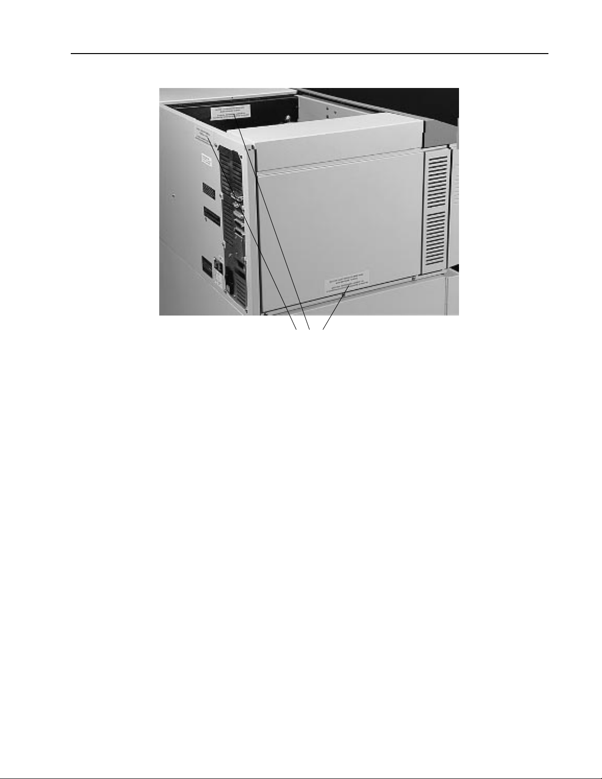
Laser Warning Labels
Figure 1-1 represents the laser warning label. This label is located inside the PantherPro on
a protective panel that encloses the laser optics, on the rear panel, and the electronics
cover. (See Figure 1-2).
CAUTION - LASER RADIATION WHEN OPEN.
AVOID DIRECT EXPOSURE TO BEAM.
ATTENTION - RAYONNEMENT LASER EN CAS
D’OUVERTURE. EXPOSITION DANGEREUSE AU FAISCEAU
Safety Label
Figure 1-1
Operator Safety
Operator access to laser radiation is not possible during operation or operator maintenance. During operation the protective housing prevents access to all radiation fields. The
recorder hinged supply cassette cover may safely be opened for operator maintenance.
This maintenance includes removing and installing the photographic media supply and
take-up cassettes.
To insure safety during maintenance, redundant interlocks shut off power to the laser diode
1-2 November 1994
PrePRESS SOLUTIONS CONFIDENTIAL
Page 8
PantherPro Image Recorder TP 8250
Laser Warning Labels
Laser Warning Label Locations
Figure 1-2
assembly (laser diode power up to 5 milliwatts at 670 nanometers could be accessible in
the machine interior if the interlocks are defeated). The PantherPro electronics and optics
covers should never be removed by the customer.
Servicing Safety
Service procedures include removal of the machine covers to replace or adjust components. The inner laser assembly and other components may be replaced in the field. The
laser output and the focused beam are accessible in the interior.
The supply cassette door includes two magnetic interlock switches which are mounted and
connected in series so that if the access door is lifted, both switches open to open the
interlock circuit. When the interlock circuit is open, all power is dropped to the current
source for the laser diode.
All service procedures will be performed with the main power shut off and with the safety
interlock circuit open (no laser diode current).
When performing alignments, carefully follow the procedures documented in the technical
manual. DO NOT defeat the safety interlock switches unless specified in the procedure.
Also, NEVER override the safety interlock switches if the polygon/motor assembly is not
spinning, as this could allow the focused beam to be emitted.
PrePRESS SOLUTIONS CONFIDENTIAL
1-3 November 1994
Page 9

TP 8250
Caution: Direct or indirect reflected eye contact with the laser beam may cause
serious eye damage.
Warning: At no time should the unit be left unattended with the interlocks defeated.
The following safety precautions should always be observed:
1. Never operate the unit with the optics cover removed.
2. Laser safety goggles must be worn when making any adjustments to the recorder with
the interlocks defeated.
3. Any adjustments that are to be made with the interlocks defeated must be made in a
secure area, with only trained personnel present.
4. Do not place screwdrivers or other shiny objects in the path of the laser beam.
5. Remove all jewelry from fingers and wrists before making any alignments.
PantherPro Image Recorder
6. Remember that the laser beam is invisible and can cause permanent damage to the
eyes.
1-3 Regulatory Agencies Information
The PantherPro is an approved product designed and manufactured in accordance with UL
(Underwriters Laboratories) and CSA (Canadian Standards Association) standards. The
product also complies with the requirements in Part 15 of FCC Rules for a Class A computing device.
This equipment complies with the requirements in part 15 of FCC Rules for a Class A
computing device. Operation of this equipment in a residential area may cause unacceptable interference to radio and TV reception requiring the operator to take whatever steps
are necessary to correct the interference.
The PantherPro also complies with specific European safety standards; international models are shipped with a label bearing the “CE” mark. This label demonstrates compliance
with IEC safety standards. The PantherPro also meets EN55022/VDE Class B emissions
standards.
1-4 Electrostatic Discharge - ESD
Static electricity is, simply, electricity that is not moving. It is harmless as long as it remains
static. Unfortunately, an electrical charge is unstable and is always looking for an opposite
charge to unite with. When a charge moves, it becomes a current, which is often greater
than a electronic circuit can handle.
The smallest static charge that can be felt is 3,000 volts; the smallest charge that can be
1-4 November 1994
PrePRESS SOLUTIONS CONFIDENTIAL
Page 10

PantherPro Image Recorder TP 8250
seen is 5,000 volts; and the smallest charge that can be heard is 10,000 volts. Some semiconductor devices are susceptible to a static charge as little as 10 volts.
Electrostatic discharge has become more and more of a hazard as microcircuit components have become smaller and more sensitive.
ESD Prevention Rules
These are the rules to be learned and followed in order to prevent ESD damage to electronic printed circuit boards and assemblies.
WARNING: Make sure you are NOT grounded when working on equipment that is
plugged in and ON.
1. Always use the antistatic portable field service kit when working on electronic parts of
PrePRESS Solution’s products or when handling printed circuit boards.
2. Make sure machine is plugged in a grounded outlet (and switched off) if using the ma-
chine frame as a grounding point.
3. Make sure your wrist strap and antistatic service kit are connected together and con-
nected to ground.
4. When replacing printed circuit boards, remove the old board from the machine before
removing replacement board from the antistatic bag. Then install replacement board
and place old board in the antistatic bag.
5. Always transport and store electronic components in an antistatic bag.
6. Use the correct size bag, not too big or not too small.
7. Keep antistatic bags in good condition. Bags with pin holes, rips, tears, or crumpled
bags are less efficient and may provide little or no protection.
8. Do not remove components from bags just to look at them. You can usually see through
the bag to identify the part.
9. Keep spare bags on hand.
10.Always ship back field returns in an antistatic bag. Even defective components should
be stored and transported in antistatic bags so that they are not damaged further.
11.Keep static producing materials such as polyester, plastic, and Styrofoam away from elec-
tronic parts.
12.Don’t pick up boards unless you are grounded or the boards are in antistatic bags. Do
not touch edge connectors on PCB’s, or exposed circuitry. Handle IC’s, and boards by
PrePRESS SOLUTIONS CONFIDENTIAL
1-5 November 1994
Page 11

TP 8250
the edges, and never place components on metal surfaces.
13.Static is present at all times, more so when the humidity is low.
14.Educate customers about static protection, especially the ones who maintain their own
equipment.
PantherPro Image Recorder
1-6 November 1994
PrePRESS SOLUTIONS CONFIDENTIAL
Page 12

PantherPro Image Recorder TP 8250
Section 2 Overview and Specifications
2-1 Product Overview
The PrePRESS PantherPro is a high speed, high-resolution, multiport image recorder. At a
recording speed of 53.3"/min, the Model PantherPro is the fastest image recorder on the
market.
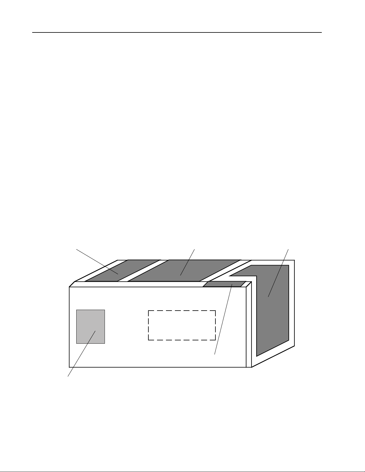
PantherPro with Base Cabinet
Figure 2-1
The Model PantherPro includes the Multiport option, which allows up to four RIPs to drive a
single PantherPro. The PantherPro is designed for configuration
PrePRESS SOLUTIONS CONFIDENTIAL
2-1 November 1994
Page 13
TP 8250
PantherPro Image Recorder
with the Adobe CPSI Level 2 software RIP.The PantherPro is driven by a standand platform microcomputer via a SCSI interface.The PantherPro offers VIM Intergrator as standard which provides OPI and DCS back-end intergration compatability.
A standard PantherPro offers ten standard resolution settings from 900 to 3048 dpi, one
input port and dual 500+ hard disk drives. Among the Pro's options are dual 1+GB Page
Buffer hard disk drives and up to three addional input ports can be added. A Pro may be
configured with either a single 500+MB or single 1+GB Page Buffer hard disk drive. All
Page Buffer Drives must be the same size.
2-2 Hardware Overview
The components of the PantherPro are located in four separate areas of the cabinet: card
cage/power supply, operator control panel, laser/optics and media transport. (Refer to Figure
2-2)
Page Buffers
Laser/OpticsHSCB / PB Module Media Transport
Power Supply
Drawer
Operator Panel
Figure 2-2 PantherPro Component Areas
2-2 November 1994
PrePRESS SOLUTIONS CONFIDENTIAL
Page 14
PantherPro Image Recorder TP 8250
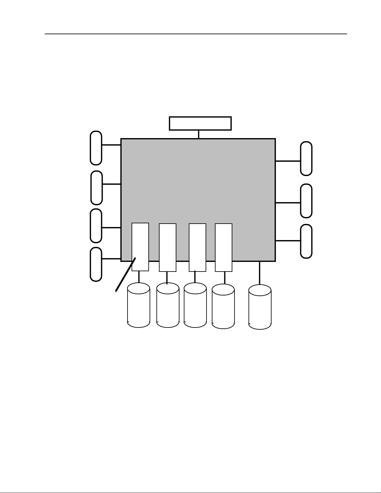
2-2.1 HSCB / PB Module (Refer to Figure 2-3, Electronics Block Diagram)
The HSCB / PB Module area is located on the left side of the cabinet and contains the High
Speed Controller Board and Page buffer Modules.
Refer to Section 3 for description of the High Speed Controller Board and Page buffer
Modules.
S
C
S
I
I
N
P
U
T
S
Page Buffer Module
PB 4
LCD / Keypad
HSCB
PB 3 PB 2
Debug
Video
Motors
PB 1 PB 0
PantherPro Electronics Block Diagram
Figure 2-3
2-2.2 Operator Control Panel
The operator control panel is located in top front of the cabinet and is used for operator
interaction with the system and for displaying operational and error messages.
PrePRESS SOLUTIONS CONFIDENTIAL
2-3 November 1994
Page 15

TP 8250
2-2.3 Laser, Optics and Media Transport
(Refer to Figure 2-4, Recorder Components Block Diagram)
The major components contained in the recorder area include:
Laser Amplifier PCB
Laser Driver PCB/Laser Diode Assembly
Leading Motor/Encoder
Polygon Motor
Polygon Drive PCB
Paper Transport Assembly
Optical System
Sensors and Switches
HSCB
PantherPro Image Recorder
Polygon High Speed Transport Motors
Driver Laser Amp Leading/Cutter
Polygon High Speed
Motor Laser Driver
Panther Pro Recorder Components Block Diagram
Figure 2-4
The recorder components, upon input from the HSCB, generates typographic characters
and graphics onto visable red sensitive paper, film or plate material.
The images are formed on the media by a laser beam output which is generated by the
video data received from the image controller. The video data is received by the laser
amplifier PCB, which then output the data to the laser driver PCB and onto the laser diode.
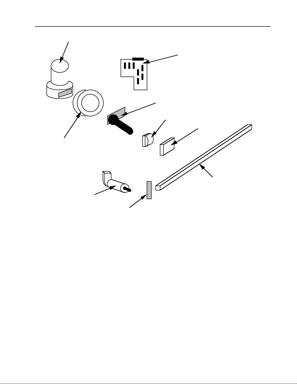
The laser diode generates the visable red laser beam which is dispersed across the imaging area by a polygon scanner motor and optical system. The paper is moved across the
imaging area by a servo leading motor.
2-4 November 1994
PrePRESS SOLUTIONS CONFIDENTIAL
Page 16
PantherPro Image Recorder TP 8250
POLYGON SCANNER MOTOR
LASER AMPLIFIER PCB
LASER DRIVER/LASER DIODE ASSEMBLY
FIRST CYLINDRICAL LENS
BEAM STEERING MIRROR
SCAN LENS
SECOND CYLINDRICAL LENS
SERVO MOTOR/
ENCODER
ASSEMBLY
SOL SENSOR
PantherPro Recorder Components
Figure 2-5
2-3 Electrical Power Requirements
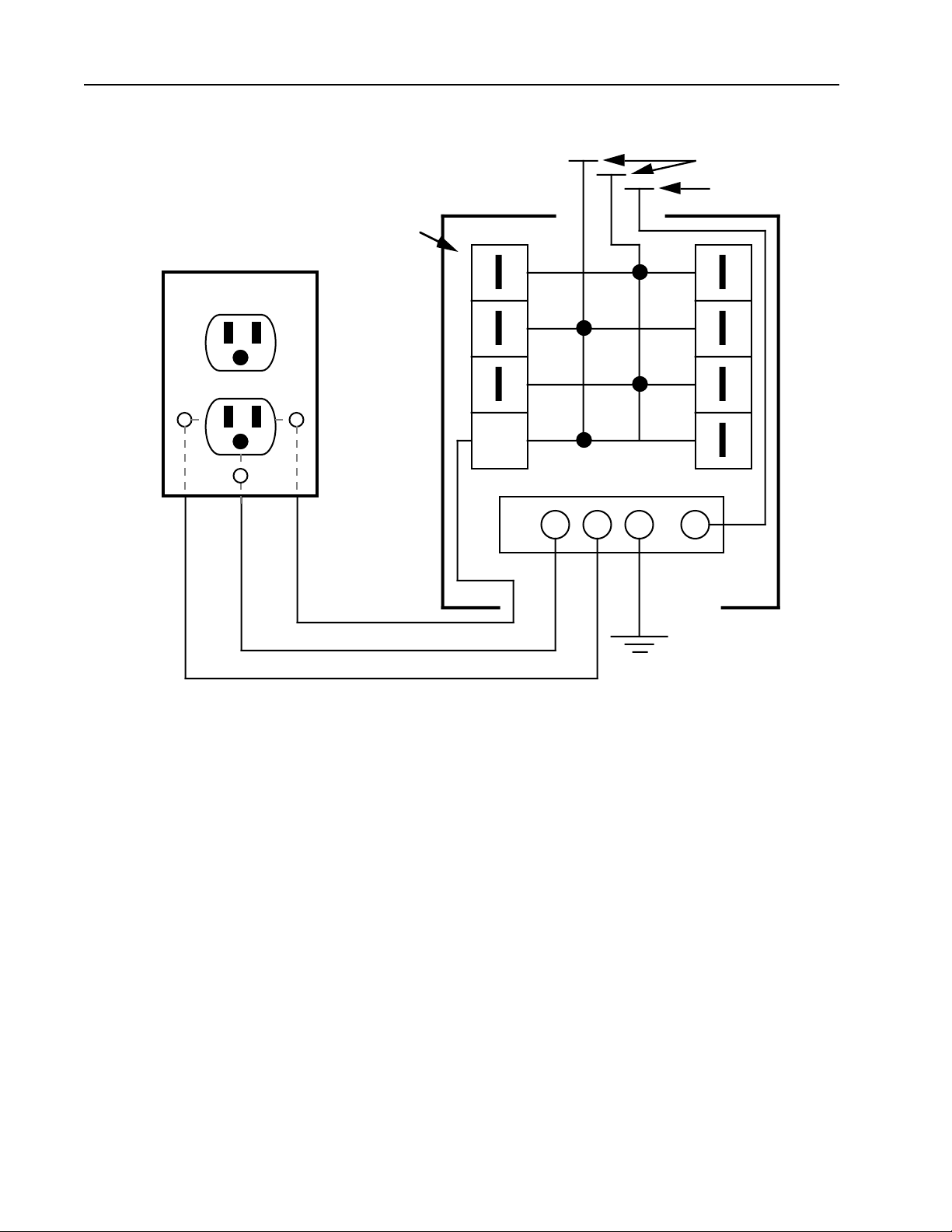
Power line to be minimum 15 amp rating, isolated with 3rd wire insulated ground wire. AC
receptacle should be Hubbel outlet Part Number IG5262 or equivalent. Refer to Figure 2-6.
Input Voltage/Power Line 115 VAC+/-10%, 60 Hz+/-3 Hz
230 VAC+/-10%, 50 Hz+/-3 Hz
Input Current Rating 2 amps/115 VAC
1 amps/230 VAC
Power Consumption 150 watts
PrePRESS SOLUTIONS CONFIDENTIAL
2-5 November 1994
Page 17
TP 8250
PantherPro Image Recorder
Heat Dissipation 500 BTU/hr.
Voltage Requirements
Hot to Neutral 115V ± 10%
Hot to Ground 115V ± 10%
Neutral to Ground .5V Max
Dedicated
AC Outlet
Main
Entrance
Box
From Power Source
115 VAC
Neutral
15
AMP
115 VAC (Black)
Third Wire Ground (Green or Green/Yellow
Neutral (White)
Input Voltage Power Line
Figure 2-6
Earth Ground
Main
Building
Ground
2-4 PantherPro Product Specifications
Maximum Line Length: 13.3 inch (338 mm)
Resolutions (H x V): 1800 x 1800, 900 x 900 (can be imaged 900 x 1800)
2032 x 2032, 1016 x 1016 (can be imaged 1016 x 2032)
2400 x 2400, 1200 x 1200 (can be imaged 1200 x 2400)
2540 x 2540, 1270 x 1270 (can be imaged 1270 x 2540)
3048 x 3048, 1524 x 1524 (can be imaged 1524 x 3048)
Spot Size: Spot size varies with resolution, from 15µm @ 1800 dpi to
3048 dpi; 30µm at 900 dpi to 1524
2-6 November 1994
PrePRESS SOLUTIONS CONFIDENTIAL
Page 18

PantherPro Image Recorder TP 8250
Absolute Accuracy: ± 0.004 inch over 18 inch
Repeatability *: ± 0.001 inch typical over 8 contiguous color separations nomi-
nal 18" in length
*Tolerance based on four consecutive pages using
PrePRESS’s High Capacity take-up cassette with 12 inch
prefeed. Actual results may vary depending on environmental
conditions and media used.
Recommended environment for color separations accuracy:
Temperature 70°F ± 3°F, Relative Humidity: 55% ± 5%
Imaging Speed: 3048 x 3048 dpi: 7.8 inches/minute (200mm/min)
2540 x 2540 dpi: 18.9 inches/minute (480mm/min)
2400 x 2400 dpi: 20 inches/minute (508mm/min)
2032 x 2032 dpi: 23.6 inches/minute (600mm/min)
1800 x 1800 dpi: 26.7 inches/minute (677mm/min)
1524 x 1524 dpi: 31.5 inches/minute (800mm/min)
1270 x 1270 dpi: 37.8 inches/minute (960mm/min)
1200 x 1200 dpi: 40 inches/minute (1016mm/min)
1016 x 1016 dpi: 47.2 inches/minute (1200mm/min)
900 x 900 dpi: 53.3 inches/minute (1,354mm/min)
(Imaging speed does not include processing and RIPing time)
Recording Method: Laser diode (670nm nominal)
Output Media: Visible red sensitive resin-coated paper, polyester film, and
plate material (up to 0.008" thickness)
Capable of accepting 8"(203mm), 11/12"(279mm/305mm),
and 13.3"(338) media
Special cassette required for .007"/.008" thickness
Output Format: Positive or negative, right or wrong reading
Supply Capacity: Up to 246' (75m) paper, film, or plate material( depending on
vendor packaging configurations)
Takeup Cassette Cassette capacity: up to 50' (15.2m) for .004" thickness film or
paper (plate material may vary)
One cassette per media width:8" (203mm), 11"/12" (279mm/
305mm), and 13.3" (338mm)
Certifications: UL 1950, CSA C22.2, FCC (Class A), Canadian DOC; EN
60950/IEC 950; all requirements of European Community
EMC Directive 89/336/EEC: Vfg 243/EN55022 Class B/VDE
Class B; EN 50082/IEC 801-2/3/4 (EM Immunity)
PrePRESS SOLUTIONS CONFIDENTIAL
2-7 November 1994
Page 19

TP 8250
Operating Environment
Temperature: 60 to 90 degrees F (16 to 32 degrees C)
Humidity: 40% to 80% non-condensing
Heat dissipation: Approximately 500 BTU/hr
Noise emission: Less than 55db
Altitude: Sea level to 7,500 ft
Recorder Dimensions: 39.5"(height) x 16.5"(width) x 24"(depth)
Recorder Weight: 165 lbs. (74.8kg)
Base Cabinet Weight 75 lbs. (34kg)
PantherPro Image Recorder
2-8 November 1994
PrePRESS SOLUTIONS CONFIDENTIAL
Page 20

PantherPro Image Recorder TP8250
Section 3 Theory of Operation
3-1 Overview
The PantherPro Imagesetting System's primary distinguishing feature is its recorder output
speed. It is approximately twice that of the Panther recorder. In addition, the PantherPro
offers up to 4 independent SCSI input ports which are accommodated by up to 5 page
buffers drives. This allows four RIPs to share the recorder.
The PantherPro Imagesetting System contains a casting, optical components, laser, laser
amplifier, leading motor/encoder, rollers, cutter, power supply, LCD/Keypad, a High Speed
Control Board, page buffer module, and page buffers.
3-1.1 Functional Overview
The High Speed Control Board interfaces the RIP Controller to the image recorder and
contains the following features:
• Up to four independent SCSI interfaces
• Minimum of 2, maximun of 5 page buffer disks
• Keypad/LCD User Interface
• Serial Port for Debug/Diagnostics
• Self-test Capabilities
• High Speed:
15.75 ipm @ 3048 DPI
18.90 ipm @ 2540 DPI
20.00 ipm @ 2400 DPI
23.63 ipm @ 2032 DPI
26.67 ipm @ 1800 DPI
• Supply Cassette configuration memory
• On-line Processor Interface
The logic circuitry is contained in the following modules:
• Input Interface
• CPU and peripherals Section
• Recorder Output Module
• Page Buffer Module
• SCSI MUX Module
3-1 November 1994 PrePRESS SOLUTIONS CONFIDENTIAL
Page 21

TP8250
3-2 High Speed Control Board (HSCB)
3-2.1 SCSI MUX Module Overview
The SCSI MUX contains the logic necessary to interface any combination of four RIPS and
five page buffers. The SCSI MUX is implemented as five four to one input ports. Each port
is designed in a modular fashion. This will allows a reduced cost for an entry level system.
It also allows each channel to be added or deleted as needed by the user.
The SCSI Mux buffers contain the interface to the connecting RIPS. The buffers for each
input port support SCSI -2 Single Ended Alternative. The connector used is a dual SCSI-2
connector, wired in common so that the SCSI port does not need to be the last device on
the bus. The lower connector of each pair is labeled 'SCSI In' and is connected to the front
end. The top connector is labeled 'SCSI Out' and is used to daisy chain other devices on
the SCSI bus only when the 'SCSI In' connector is already used. SCSI bus termination is
achieved through active terminators. This means that the SCSI port will sense if the port is
the last on the SCSI bus or in the middle of the chain and terminate if necessary.
3-2.2 SCSI MUX Control Logic
There are four registers used by the control logic: an ID register, a select register, a revision register, and an arbitrate register. Only the select register is read/write. All registers
are 16 bits wide. Bits not used are not driven. Byte access is not supported.
PantherPro Image Recorder
3-2.3 SCSI MUXS
The MUXS are implemented using 160 pin gate arrays. The arrays incorporate all of the
muxs for five channels and the control logic needed to select the direction of the SCSI data
bus, and the signals BSY~ and SEL~.
3-2.4 SCSI MUXTest Path
Testing of the SCSI Mux channels are done by connecting a cable (loopback) from the
page buffer 0 disk SCSI connector to the port to be tested.
3-3 CPU and Peripherals Module Overview
3-3.1 Microprocessor
A Motorola 68000 running at 16.67 MHz is utilized to provide processing power for the
HSCB.Code is executed out of program storage. Upon request it will relinquish the bus to
other bus masters.
3.3.2 Program Storage
An EPROM is provided for program storage. This is a 'by 16' part. The EPROM resides at
location 0 and at location 0x200000 at powerup. Once the program code starts executing
out of the 0x200000 space, the EPROM will no longer reside at location 0.
3-2 November 1994
PrePRESS SOLUTIONS CONFIDENTIAL
Page 22

PantherPro Image Recorder TP8250
3-3.3 DATA Storage
A DRAM storage system is provided for CPU data storage. This provides 2 MB of memory.
The DRAM is enabled at location after the EPROM starts executing code out of its upper
space.
The DRAM consists of 4 1MB x 4 parts. A DRAM controller generates read, write, and
refresh cycles to the DRAM. The design supports use of 4 256K x 4 parts, providing 512K
of memory.
3-3.4 Nonvolatile RAM
A 2k byte NVRAM is provided. It resides on the upper 8 bits of the 68000 data bus. Its base
address is 0xD00000.
3.3-5 Interrupt Controller
The interrupt controller receive interrupts from each page buffer module and from peripherals. Page buffer modules are capable of generating 3 interrupts; one from the HODT_SIOP,
one from the Disk_SIOP and one from the 3210 Compressor/Decomprocessor chip.
The Disk_SIOP and the 3210 that is imaging is given priority level 5. A mask register is
loaded indicating which page buffer is imaging. All other Page buffer interrupts share interrupt level 4. Interrupt vectors are provided for each interrupt level.
3-3.6 DUART/Timer
A 2681 DUART/Timer will be used. This will provide 2 serial channels. They are configured
as DCE.
The timer is programmable. Interrupts are generated when certain DUART conditions are
net or when the timer expires. The DUART resides at address D10020 through D1003F.
3-3.7 Keypad Interface
An interface to a keypad is provided. This interlace provides a means to reset the hardware
by monitoring a sequence of keystrokes. The keypad address resides at location
D10042
3-3.8 Address DecodeNnecessary address decodes are generated for page buffer modules, SCSI MUX modules, and recorder output module.
3-3.9 Strobe/Dtack Logic
I/O strobes, read and write will be generated for I/O devices. Dtack is generated for I/O
devices, memory, and registers.
3-3.10 LCD Interface
An interface to the graphics LCD is provided. An additional timer is provided to generate
100 µsec interrupts to update the LCD. The LCD resides at address D10044 through
D10046.
3-3.11 Diagnostic LED Bank
A software programmable diagnostic LED bank is provided. This consists of 8 LED's. They
3-3 November 1994 PrePRESS SOLUTIONS CONFIDENTIAL
Page 23

TP8250
are enabled upon powerup.
3-3.12 Dead Man Timer
A dead man timer circuit is provided such that if not reset every 2 seconds a hardware
reset will occur.
3-3.13 Clock Circuitry
Clocks are generated for the CPU, the page buffer modules and the DUART/Timer. A slow
clock will be generated for the dead man timer.
3-4 Page Buffer Module Overview
Each PBM consists of two NCR 53c7000 SCSI input/output processors (SIOPs), one
AHA3210 Compression Coprocessor (in future revisions), 512kb of DRAM, a disk drive and
the circuitry to control the data movement among them.
3-4.1 Clock Generator
the main clock is derived from a crystal oscillator (33.34 MHz) that is at twice the frequency
that the MC68000 will operate. This clock is divided in half and synchronize d to the crystal
oscillator with reset. The 16.67 MHz rate is then used to run the 68000, the AHA3210's,
and as a reference for the SIOP control Logic. While the SIOPs are clocked at the faster
33.34 MHz rate, internally the run at 16.67 MHz. The control logic must be aware of both
rates to properly sequence the slave cycles between the 68000 and the SIOPs.
PantherPro Image Recorder
3-4.2 68000 Bus Arbitration Logic
Each PBM has two SIOPs, which can be bus masters. For a fully configured HSCB (5
PBMs present) there are a maximum of ten devices that may request to become a 68000
bus master. Since only a single device can own the bus at any one time, bus arbitration
logic must be implemented to control which requesting device is driving the 68000 bus. The
priority is always given to the PBM that is imaging. Any request from any input PBM is
granted only if there are none pending from the output PBM. The priorities are as follows:
1. Output PBM
2. Output PBM host SIOP
3. Input PBM disk drive SIOP
4. Input PBM host SIOP
If no output PBM requests are made, the input PBMs are granted the bus in a rotating
order.
3-4 November 1994
PrePRESS SOLUTIONS CONFIDENTIAL
Page 24

PantherPro Image Recorder TP8250
3-4.3 NCR 53C700 SIOP
The NCR53C700-66 is a high speed SCSI controller with a built-in SCSI SCRIPTS processor to perform SCSI SCRIPTS operations with minimal intervention from the HSCBs 68000.
The SIOP must be operated in 80286 mode (16 bits) to accommodate the 68000. Since the
53C700 is an Intel compatible device (Little Endian), byte swapping occurs in the hardware
for any access between the 68000 and the SIOP. The data rates supported by this device
are 5.0 MB/Sec in asynchronous mode and 10.0 MB/Sec in Synchronous mode. This chip
contains a SCSI controller, a 32 byte FIFO, a high performance DMA controller and a 2MIP
"SCRIPTS" processor that manages the data transfers to and from the HSCB local
memory.
There are two independent SCSI channels as part of this submodule. The first SCSI channel will provide an interface to the host system via the SCSI MUX Module. This SIOP is
setup to DMA the input data from the host SCSI bus to port A of the 3210. The 3210 Port A
is configured for slave mode and will compress data as the SIOP writes to port A of the
3210. The SIOP interrupt signals as the predetermined block size of data has been sent to
the compressor port from the host.
The second SCSI channel provides an interface to the page buffer disk. The page buffer
disk stores compressed data from port B of the 3210. During compression, this second
SIOP will read blocks of data from a local DRAM buffer and write it back to the drive. Later,
the whole compressed job is read back, decompressed, and imaged.
3-4.4 AHA 3210 Compression Coprocessor
The 3210 is used to compress the data received from the host SIOP for storage on the disk
or to decompress the stored job for output to the recorder output module.
Initially, the host SIOP is set up in 80286 mode. The SIOP fetches instructions from the
68000 memory by becoming a bus master of the 68000. The 3210 is set up for compression with port A as a slave and port B as a master.
3-5 Recorder Output Module Overview
3-5.1 Dual Port Video Memory
A 256k x 16 Dual port Video Memory operates as a large FIFO buffer. This memory consists of field RAM, which contain address generation and refresh/read/write arbitration
internally. It is loaded with uncompressed data from a page buffer module, and is output to
the Scan Line FIFO.
The Dual Port Video Memory must be reset before each image.
3-5.2 Scan Line FIFO
The Scan Line FIFO is 16 bits wide. It provides a full scan line of buffering at the highest
resolution. Writes into the FIFO occur as a two-clock (minimum) cycle at the system clock
rate which can stifle subsequent writes.
Data from the Video FIFO is read one byte at a time or as needed to load the video shift
register.
The FIFO 'Retransmit' signal is used to repeat scan lines. This requires the hardware to
3-5 November 1994 PrePRESS SOLUTIONS CONFIDENTIAL
Page 25

TP8250
reset the FIFO before each scan line. Upon reset, the Dual Port Video Memory transfers
one full scan line into the Scan Line FIFO, and then outputs the scan line in real time to the
video shift register. If the scan line is to be repeated, the scan line is retransmitted from the
Scan Line FIFO. The process is repeated for the next scan line.
3-5.3 Xcount
An Xcount register and counter contains the number of words per scan line, counting the
words transferred into the Scan Line FIFO. When the full number of words is reached,
transfers stop with the Scan Line FIFO holding a complete scan line. The Xcount register
requires loading once per image.
3-5.4 Margin and Blanking
A programmable margin is provided by the Margin Register. For each scan line, a margin
counter is loaded with the margin register contents and counted down to zero. The video is
blanked, and reading from the FIFO is inhibited until the this margin is exhausted. Once
reading from the FIFO commences, the real video is output till the right edge of the media
is reached, and the video is again held blank.
PantherPro Image Recorder
3-5.5 Fill
A fill feature allows blank scan lines to be output without fetching of video data. This allows
images to be transmitted to the Panther Pro without the corresponding 'blank' data. The fill
feature supports automatic blanking at a granularity of single scan lines.
3-5.6 Video Control
Circuitry will count pixels, load the shift register, and issue reads to the Scan Line FIFO at
appropriate times. This circuitry is collectively known as video control.
3-5.7 Test Pattern
Capability to substitute a hardware generated test pattern for normal video is provided.
Each square of the test pattern measures 128 pixels square.
3-5.8 Serialization
Video output to the laser amplifier is a serial stream. Bytes of video from the Scan Line
FIFO is serialized in a shift register and then turned into a stream of pulses before being
output to the Laser Amplifier.
3-5.9 PCLK Synchronizer
A clock phase which best matchs the START pulse selects each scan line and output a
new PCLK. This will minimize left edge jitter, keeping it to within a fraction of a pixel.
3-5.10 Intensity Control
A register which drives a D/A converter will set the laser intensity. This is the identical
circuit used on the RCB.
3-6 November 1994
PrePRESS SOLUTIONS CONFIDENTIAL
Page 26

PantherPro Image Recorder TP8250
3-5.11 Facet Timer
A Facet Timer circuit times the scan line and issue various control signals whose timing is
related to the scan line. Examples of such signals are: Sample/Hold, Enhance, Inhibit Bias,
Speed hi/lo/ok, End of scan, etc. The decoding of these signals is fixed, and is oriented to a
specific exspected polygon rotational rate.
3-5.12 End of Scan interrupt
A maskable interrupt is generated once per scan duing the inactive portion of a scan line.
3-5.13 Polygon Speed control
Polygon Speed Control consists of a 16 bit register and a 16 bit counter. On overflow, the
counter is loaded from the register, creating a programmable time base. The output of this
circuit is the square wave POLYCLK, which is fed to the polygon drive circuitry and resides
on a separate circuit board.
3-5.14 Leading Motor Control
The Leading Motor Control consists of a paper feed register, an adder/accumulator, and a
Galil GL1200 motor control IC. The adder/accumulator produces a series of pulses at a rate
set by the Paper Feed register. The GL1200 converts this into postion information, comparing with encoder inputs. Also the GL1200 outputs velosity information. The position and
velocity information are summed with the accelerator information to form the input to the
motor drive. A nearly identical circuit is used on the RCB.
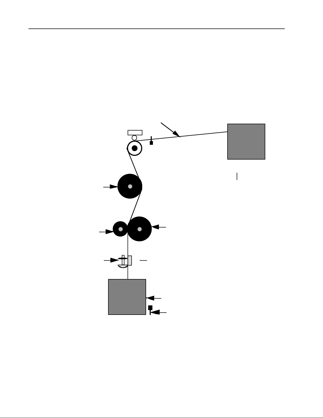
3-6 Paper Transport Assembly
(Refer to Figure 3-1 Paper Feed Diagram)
The paper transport assembly is used to accurately feed the infrared sensitive media from
the supply cassette through the exposure window and into the take-up cassette. The paperfeed mechanism is a capstan drive roller feed device driven by a servo motor under logic
control. The paper transport is capable of feeding 8", 12", or 13.3" media.
The supply cassette is a plastic box with end plates. Inside it contains two margin plates
with core spindles which are adjustable for different paper widths. The maximum roll
lengths that fit in the supply cassette are 246 feet for paper or film.
The media is drawn out of the supply cassette and across the tensioner & metering rollers.
The External Tensioning Modual (ETM) sits on top of the metering roller to regulate accuracy and scewing of the media transport. The backside of the media is then drawn across
the imaging roller where the exposure plane is. The media is pulled by the drive and pressure roller, past a power cut-off knife and into a take-up cassette.The knife is a automatic
power rotary knife assembled in a carriage which transverses across the paper feed. The
knife can also be operated manually. (Refer to figure 3-2, Rotary Knife.)
3-7 November 1994 PrePRESS SOLUTIONS CONFIDENTIAL
Page 27
TP8250
PantherPro Image Recorder
Rotation of the knife is transmitted through an O ring which is mounted axially on the same
shaft. The O ring is rotated due to frictional contact with the paper-hold-down bar. The bar
is spring-loaded upwards to permit passage of the paper. It is compressed downwards by
the O ring holding the paper stationary during the cutting stroke.
After the cutting operation, the knife carriage must be positioned at the extreme end of its
stroke (left or right), so it is not pressing down on the hold-down bar; otherwise, paper
cannot be advanced and a paper jam will occur.
MEDIA
ETM
IMAGING ROLLER
PRESSURE ROLLER
ROTARY KNIFE
SUPPLY CASSETTE
DRIVE ROLLER
STATIONARY KNIFE
TAKE UP CASSETTE
CASSETTE OUT SWITCH
Paper Feed Diagram
Figure 3-1
3-8 November 1994
PrePRESS SOLUTIONS CONFIDENTIAL
Page 28

PantherPro Image Recorder TP8250
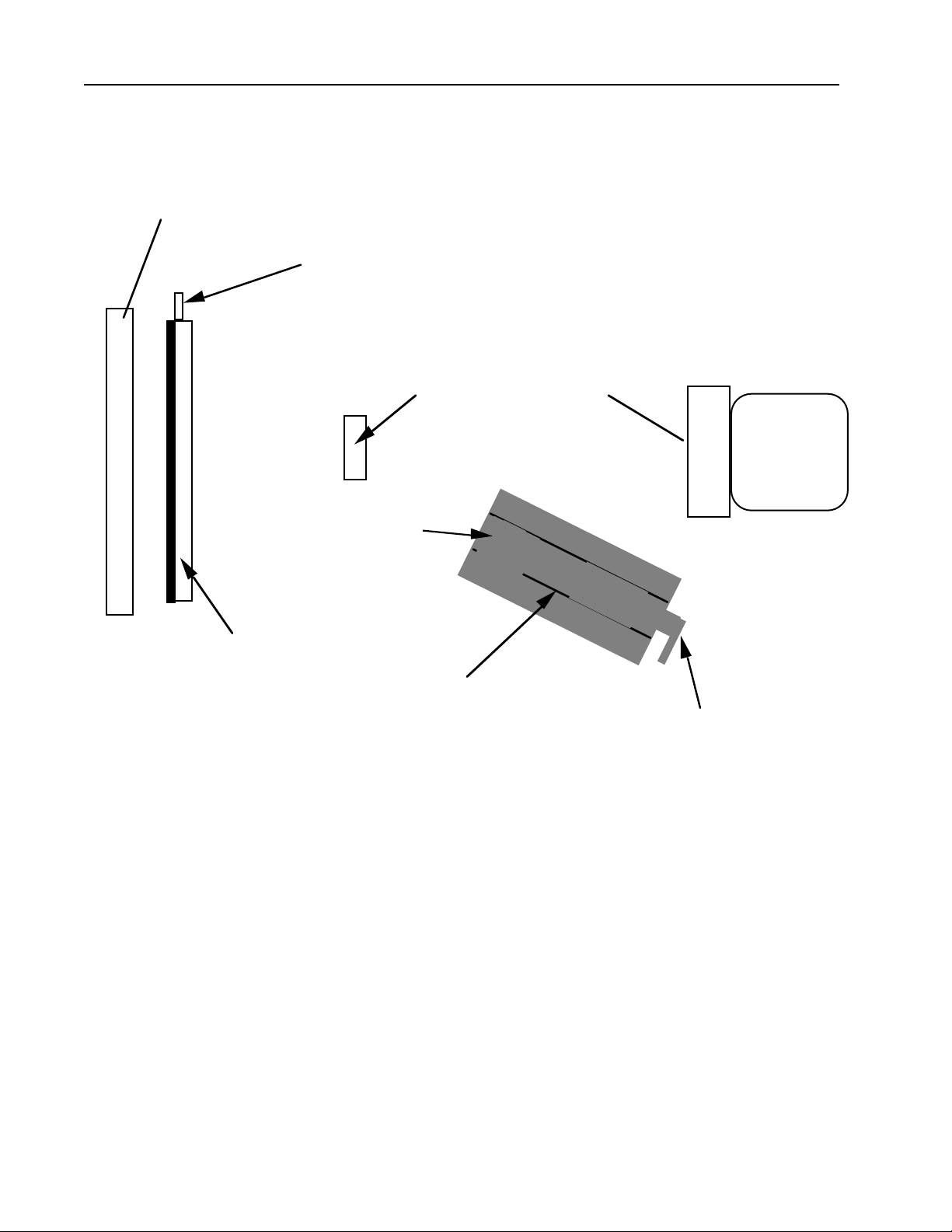
3-7 Optical System (Refer to figure 3-3, Optical System.)
The function of the optical system is to image a series of 0.0006 inch spots in a straight line
across a 13.3 inch maximum flat field.
The light for the PantherPro recorder optical system is generated by a visible laser diode
operating at 670 nanometers. The light rays originate on the laser diode, then pass through
the laser diode lens contained within the diode assembly. The rays then come to a focus
about 1.5 inches beyond this lens. Once past the point of focus, the ray bundle which is
formed by the light rays begins to diverge.
This expanding ray bundle then passes through the first cylinder lens. The first cylinder lens
causes the vertical diverging beams to re-converge while allowing the horizontal beams to
continue their divergence. The function of the first cylinder lens is to focus a this horizontal
line of light on the polygon facet. This controls vertical focus on the film plane.
After passing through the first cylinder lens, the bundle is redirected toward the scan lens
by the beam steering mirror. The function of the beam steering mirror is only to position the
beam correctly into the scan lens.
The bundle enters the scan lens and horizontal divergence is stopped and a 20mm wide
horizontal collimated beam is formed. This 20mm beam then strikes the scanning facet of
the polygon. It is reflected back through the scan lens at a continuously varying angle. The
horizontal beam is now converging toward the image plane. The vertical beam is now
expanded slightly.
The bundle next passes through the second cylinder lens. Optically this lens causes the
vertically diverging beam to quickly converge to focus on the film plane. Since the horizontal beam is already converging due to the effects of the scan lens, the second cylinder lens
is responsible for both vertical focus and polygon wobble correction.
The PantherPro optics are non-symetrical meaning the vertical and horizontal axis behave
independently of each other.
The X, Y, and Z axis's are defined as follows;
Z axis - The line alongn the beam center from the diode to the center of the scanline.
X axis - This is the scanline sweep horizontally across the measure.
Y axis - This is the beam height from top to bottom. This is the same direction as the
media transport.
The PantherPro was designed to require no field optical adjustments. All spare parts are
pre-adjusted and ready to install without adjustment in the field. To ensure repeatability and
consistency, all parts are aligned on the same factory fixtures.
3-9 November 1994 PrePRESS SOLUTIONS CONFIDENTIAL
Page 29
TP8250
There are a number of components that make up the Panther Pro Optical bed. It comprises
of a laser/laser driver, 1st cylindrical lens, beam steering mirror, scan lens, polygon, second
cylindrical lens, second cylindrical lens mask, and imaging roller.
Imaging Roller
SOL / SOL Amplifier PCB
PantherPro Image Recorder
Beam Steering Mirror
1st Cylindrical Lens
2nd Clyindrical Lens and Mask
Laser Assembly Stop
Figure 3-3 Panther Pro Optics
Laser Diode - The laser diode produces a visible red beam that constantly spreads out in
both the horizontal and vertical directions (X and Y axis) as it travels away from the diode.
The laser beam spreads out 3 times faster in the horizontal direction than the vertical.
Scan Lens
Polygon
Laser Diode / Laser Driver
Laser Diode Lens (not shown) - This lens, which is part of the laser tube, reduces the
spreading of the beam by 10 times by focusing the beam to a spot 1.5" beyond the diode.
This focal point is exactly at the end of the diode tube.
1st Cylindrical Lens - The 1st cylindrical lens cuts the spreading of the beam down in the
vertical or Y axis. The horizontal or X axis direction is not affected by the lens and therefore
the beam continues to spread horizontally. This affect focuses the beam on the Y axis on
the polygon to ensure wobble correction for the polygon mirrors.
3-10 November 1994
PrePRESS SOLUTIONS CONFIDENTIAL
Page 30

PantherPro Image Recorder TP8250
Beam Steering Mirror - This mirror allows for the adjustment of the beam in the Y axis. The
beam must be adjusted to pass through the mask opening on the second cylindrical lens.
Scan Lens - Focuses the lens vertically to a spot on the polygon.
Polygon - The polygon contains eight mirror facets which reflects the laser beam onto the
horizotal sweep of data across the media measure. Each mirror facet is one scanline.
Second Cylindrical Lens - Focuses the beam to the correct spot size in the Y axis. The lens
also pulls the beam to the center in the Y axis direction which also helps to correct for
polygon wobble.
Second Cylindrical Lens Mask - This mask cuts away unwanted reflections of the laser.
Imaging Roller - This roller positions the media so that it is in the correct focal distance from
the laser.
3-8 Sensors and Switches
The PantherPro recorder area contains the following detectors and switches:
Start of line detector
Paper out switch
No cassette switch
Safety interlock switches
Take-up door open switch
Media Jam detector
The start pulse detector pickup is mounted on the left margin area of the second cylinder
lens assembly. It detects the laser beam start signal and sends it to the laser amplifier
PCB.
The paper-out switch is a mechanical switch located on the media-feed assembly that
senses the left edge of the paper. When paper is not detected, the switch closes, the signal
is sent to the video interface PCB, and a message is displayed on the operator panel LCD
screen of the controller.
The no-cassette switch is a mechanical switch located on the on the side of the take up
cassette mounting area that senses the presence of the media take-up cassette. When the
cassette is not detected, the switch closes and the signal is sent to the video interface PCB,
and a message is displayed on the operator panel LCD screen of the controller.
3-11 November 1994 PrePRESS SOLUTIONS CONFIDENTIAL
Page 31

TP8250
The safety interlock switches are magnetic switches mounted on each side of the main
chassis by the paper feed top cover. The switches are designed to open when the door on
top of the recorder unit is opened. The signal that goes through the switches is 12 volts,
which is used to power the laser diode, so that, when the door is opened, the switches are
open and no power is supplied to the laser diode.
The take-up door open switch is located on the take-up door. It is in series with the no
cassette switch. Its function is to warn a remote front-end that the take-up door is open and
the media will be fogged.
Media jam detection is performed by the servo controller IC on the RCB. The servo controller IC senses severe loss of phase lock, and reports it as a media jam.
PantherPro Image Recorder
3-12 November 1994
PrePRESS SOLUTIONS CONFIDENTIAL
Page 32
PantherPro Image Recorder TP 8250
Section 4 Power Supply and Distribution
4-1 AC Power
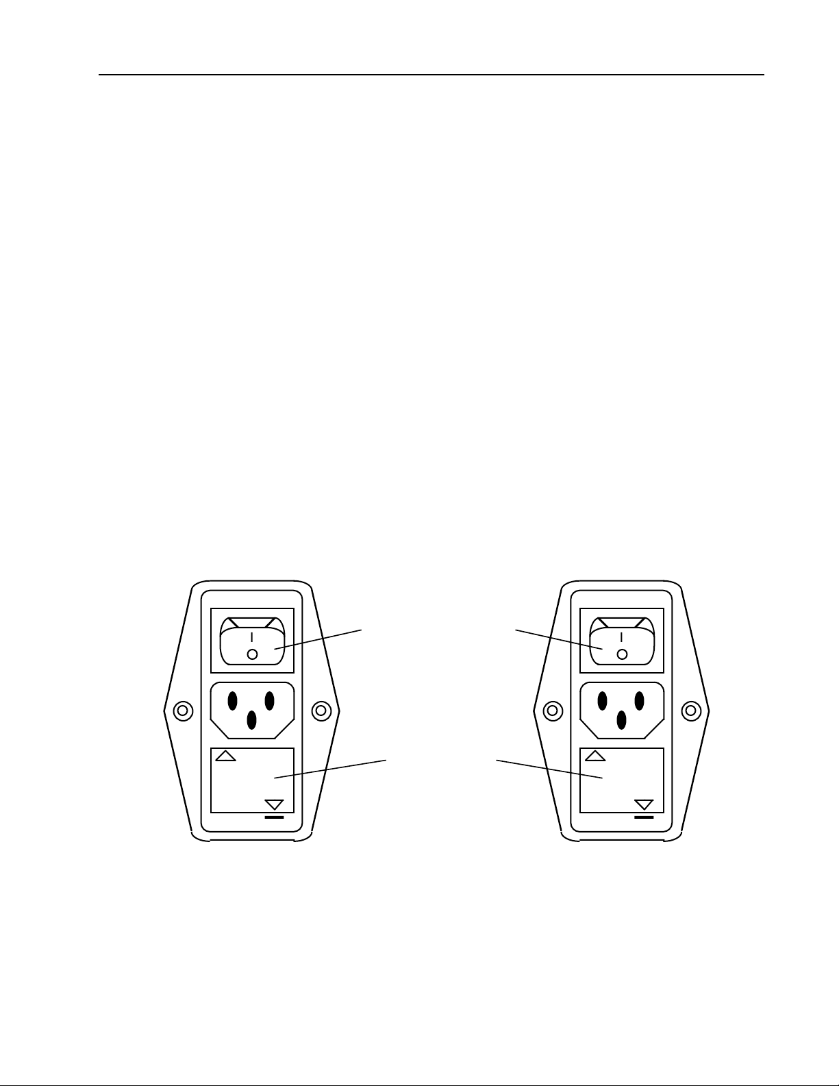
The AC power is supplied to the PantherPro through the removable power cord that plugs
into the receptacle located on the rear of the unit. The receptacle is part of the main power
switch assembly module, which also includes the main AC fuse, and RFI filter. The module
can be used for 115 VAC and 230 VAC operation and is converted by turning the fuse
housing and lining up the arrowhead with the arrowhead on the module housing (Refer to
figure 4-1, Main Power Switch Module Voltage Position) and by setting the jumpers on the
Power Supplies.
CAUTION: For continued protection against fire hazard, replace fuse only with same type
and rating.
Main ON/OFF Switch
220-240V
110-120V
115V Position 230V Position
Main Power Switch Module Voltage Positions
Fuse Housing
For 115V Use 4A Fuse
220-240V
For 230V Use 2A Fuse
Figure 4-1
110-120V
PrePRESS SOLUTIONS CONFIDENTIAL
4-1November 1994
Page 33
TP 8250
PantherPro Image Recorder
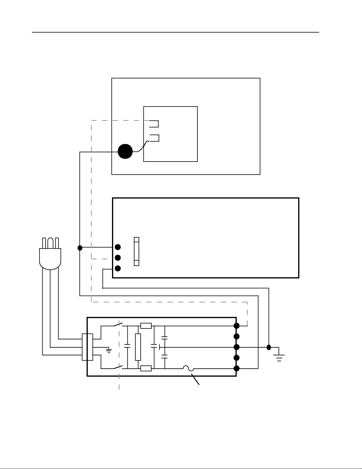
The neutral and hot wires from the main switch module are connected to the AC input
terminals on the power supplies. The ground wire is connected to the chassis. (Refer to
Figure 4-2 AC Distribution Diagram)
Condor HN24-3.6-A+
4
Blu
Brn
1
Fus e
GROU N D
AC HO T
A C NE UTRA L
A C Line Cord
Zenith ZPS 300A
Bro wn
Blu e
Gn/Y
Fus e
PO WER LINE FILTER WITH SWI TC H A N D FU SE
2
N
P
4
3
1
N/C
N/C
Ground
Main ON/OF F S wi t c h
AC Distribution Diagram
Figure 4-2
4-2 November 1994
PrePRESS SOLUTIONS CONFIDENTIAL
Page 34
PantherPro Image Recorder TP 8250
4-2 DC Power
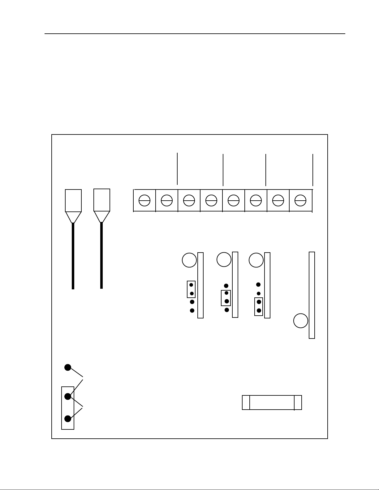
The power supplies for the PantherPro are located under the optics bed. It is accessible
from the rear of the recorder. It uses the Zenith supply for 5Vdc, +/-12Vdc. The Condor
supply is +24Vdc only, and is used to drive the polygon.
The power supply output specifications are as follows:
+5VDC-4.5-45 Amps; +12VDC-.6-6 Amps; –12VDC-1 Amps
Refer to Figure 4-3 for Power Supply Connection Points.
System Drives System/Fans
+5V
RED
BLK
Not to Scale
+12V
GRY BLK GRY BLK BLK BLU
To RCB To Drives
+12Vdc Adj +12Vdc Adj -12Vdc Adj
+12V
-12V
6 7 83 4 51 2
5Vdc
Adj
Input Power Jumper Select
230 VAC
115 VAC
Zenith Power Supply Connection Points
PrePRESS SOLUTIONS CONFIDENTIAL
115Vac - 4A Fuse
230Vac - 2.5A Fuse
Figure 4-3
4-3November 1994
Page 35
TP 8250
PantherPro Image Recorder
Brown
Wire
Blue Wire
Condor HN24-3.6-A+
Power Supply
4
3
2
1
5
110V strap 4 to 3 and 1 to 2
220V strap 2 to 3
Input
Purple Wire
Black Wire
Voltage Adj
Output
Condor Power Supply Connection Points
Figure 4-4
4-4 November 1994
PrePRESS SOLUTIONS CONFIDENTIAL
Page 36

PantherPro Image Recorder TP8250
Section 5 Installation
DANGER: Invisible laser radiation is present when the recorder is open and the
interlocks defeated. Avoid direct exposure to beam.
Note: Maintain all Anti-Static procedures for PC boards while performing the installation procedure.
5-1 Bill of Materials
The PantherPro Imagesetter is shipped with the following items necessary for installation:
Line Cord (110V Domestic Only)
Supply Cassette
Take-Up Cassette
Operator Documentation
SCSI Cable
5-2 Pre-Installation Procedure
5-2.1 Ensure that the site is large enough in square feet to accommodate unpacking, installation, future service and final machine location before unpacking the unit.
5-2.2 Inspect all shipping cartons for any apparent damage; note any damages on installation report.
5-2.3 Remove equipment from shipping cartons. Verify contents against Bill of Materials
and Customer Order Form, note any missing items on installation report. Items missing and
checked as packed should be ordered through MOCP. Items missing and back ordered
should not be ordered through MOCP.
5-2.4 Inspect equipment for any physical damage, note any damage on installation report.
5-2.5 Remove the shipping foam from the supply cassette area. Also check for factory final
copy. This sample should be compared with copy quality after upacking and setup.
5-1November 1994 PrePRESS SOLUTIONS CONFIDENTIAL
Page 37

TP8250
5-3 Electrical Requirements
Step 1. Verify that the AC outlet to be used meets PrePRESS Solutions's electrical require-
ments. (Refer to section 2-3 of this manual.)
Step 2. If the outlet meets the electrical specifications, continue with the installation.
Step 3. If the outlet does not meet the electrical requirements, do not proceed with the
installation. Notify the District Service Manager.
5-4 Installation Procedure
Step 1. Place unit on top of a table or optional cabinet.
Step 2. Remove the electronics cover.
Step 3. Verify that the High Speed Control Board is properly installed in the card cage.
Step 4. Reseat all cables on the Recorder Control Board.
PantherPro Image Recorder
Step 5. Remove the optics cover and reseat all cables connecting the Laser Amp and
Polygon PCB's.
Step 6. Verify switch setting of High Speed Control Board and Page Buffer Module. Refer
to Section 8.
Step 7. Inspect card cage area for debris, etc. Correct any problems.
Step 8. Inspect all interconnecting cables and plugs for proper seating.
Step 9. Make sure that main power switch is OFF.
Step 10. Install the line cord, female end into the filter at rear of unit and male end into an
approved AC outlet.
Step 11. Turn power ON.
Step 12. Check fans for proper operation.
Step 13. Check DC voltages. If voltages need adjustment, perform Step 13a.
Step 13a. Adjust the +5, +12, and -12 volts to the following specifications:
+5v +5.1 volts dc +/- .1 volts
+12v +12.0 volts dc +/- .3 volts
–12v –12.0 volts dc +/- .3 volts
Refer to Section 4 for for power supply voltage adjustments location.
Step 14. Turn power OFF.
5-2 November 1994
PrePRESS SOLUTIONS CONFIDENTIAL
Page 38

PantherPro Image Recorder TP8250
5-5 System Test
Step 1. Install starter kit and convert take up cassette if necessary to smaller size
from default 13.3".
Step 1. Turn power ON
Step 2. Connect personal computer to unit and run diagnostics. Refer to Section 7.
Step 3. Connect and launch RIP and configure for customer operation.
Step 4. Check line length and leading adjustments by running copy quality tests. Compare
the quality od this test copy with the factory final test copy. If there are any differ
ences in quality, make any necessary adjustments. Refer to Section 8.
5-6 Installation Completion
Step 1. Turn power OFF.
Step 2. Re-install covers previously removed with appropriate hardware.
Step 3. Place system in permanent location.
Step 4. Turn power ON and verify that system loads programs.
Step 5. Clean up area.
5-3November 1994 PrePRESS SOLUTIONS CONFIDENTIAL
Page 39
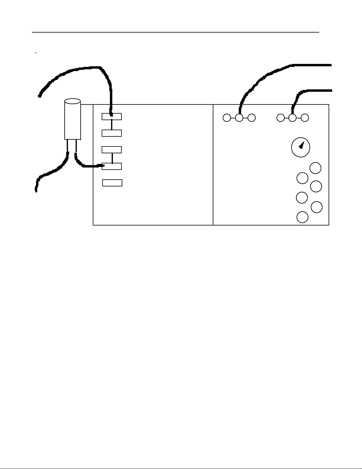
PantherPro Image Recorder
TP8250
Section 6 Removal/Replacement
DANGER - Visible red laser radiation when the top cover is open and interlock defeated. Avoid direct exposure to beam.
CAUTION - Use of controls or adjustments or performance of procedures other than
those specified herein may result in hazardous radiation exposure.
NOTE - Maintain all Anti-Static procedures while performing removal/replacement
procedures on pc boards.
6-1 External Covers and Panels
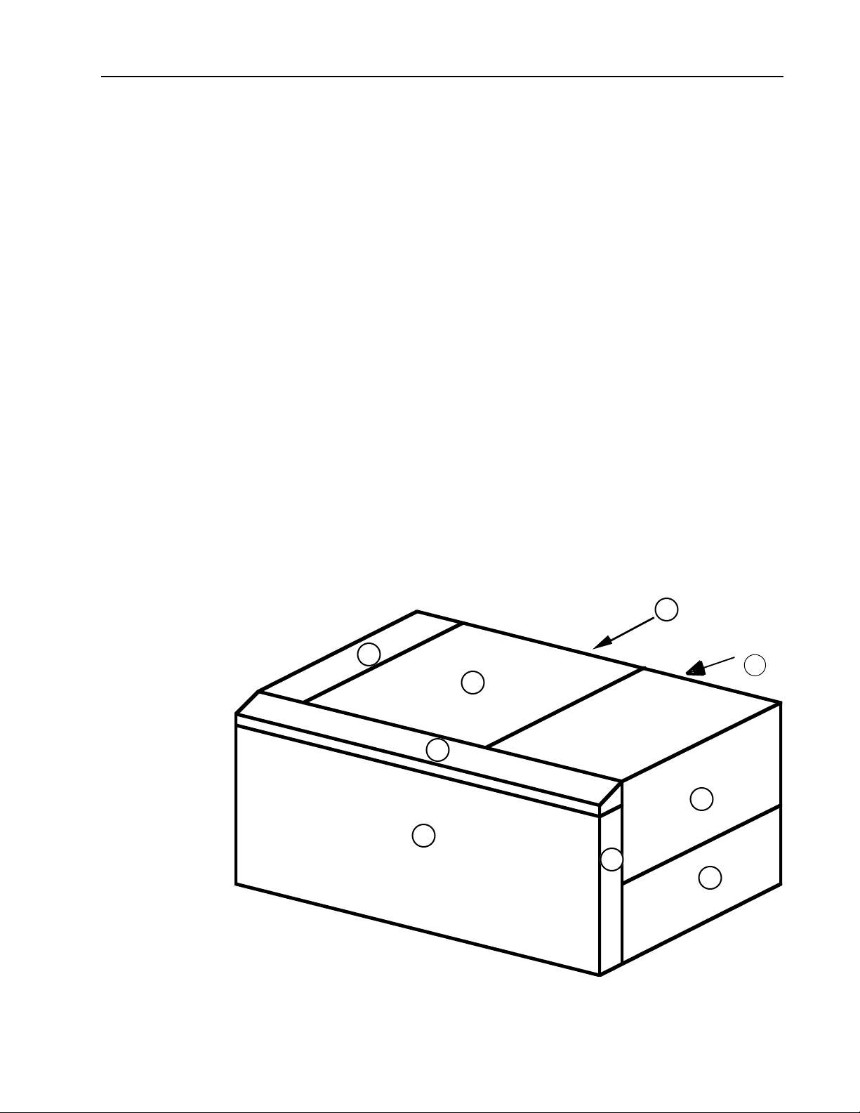
The external covers and panels of the PantherPro can be identified by referring to Figure 6-
1.
A - Front Panel
B - Electronics Cover
C - Optics Cover
D - Rear Cover
E - Supply Cassette Door
I
D
F - Take Up Cassette Door
G- Control Panel
B
H - Filter Panel J
J - Power Supply
C
Drawer
G
E
A
H
F
PantherPro External Covers
Figure 6-1
PrePRESS Solutions CONFIDENTIAL
6-1November 1994
Page 40

TP8250
6-1.A Front Panel
Step 1. Remove the 4 top screws and 4 bottom screws that mount the front panel to the
main chassis.
Step 2. Replace front panel in reverse order of removal.
6-1.B Electronics Cover
Step 1. Loosen the 3 screws that secure the bottom of the cover to the main chassis.
Step 2. Lift cover up to disengage locator pins and remove.
Step 3. Replace electronics cover in reverse order of removal.
6-1.C Optics Cover
Step 1. Remove Electronics Cover. See figure 6-1.B.
Step 2. Slide optics cover towards left side to remove.
PantherPro Image Recorder
Step 3. Replace optics cover in reverse order of removal.
6-1.D Power Supply Drawer
Step 1. Remove 7 mounting screws on the power supply drawer.
Step 2. Pull drawer out half way. Remove connectors on power supplies.
Step 3. Remove drawer.
Step 4. Replace power supply drawer in reverse order of removal.
6-1.D Rear Cover
Step 1. Open Supply Cassette Door and Take Up Cassette Door.
Step 2. Remove the 2 screws that mount the support bar to the rear cover. The support bar
connects the rear cover to the front of the chassis, located above the knife area.
Step 3. Remove power supply drawer.See figure 6-1.D.
Step 3. Remove the 15 mounting screws on the rear panel.
Step 4. Pull rear cover away from chassis, and disconnect the cable connectors from the
cables going to the interlock switches.
Step 5. Remove rear cover.
Step 6. Replace rear cover in reverse order of removal.
6-2 November 1994
PrePRESS SOLUTIONS CONFIDENTIAL
Page 41

PantherPro Image Recorder
6-1.E Supply Cassette Door
Step 1. Open take-up cassette door.
Step 2. Remove Rear Cover (figure 6-1.D). (Loosening the screws on the left side of the
rear cover is all that might be necessary.)
Step 3. Lift door out of pin hinge.
Step 4. Slide hinge out of track to remove door.
Step 5. Replace supply cassette door in reverse order of removal.
6-1.F Take Up Cassette Door
Step 1. Open the take up cassette Door.
Step 2. Remove the shoulder screw that mounts the support wire cable to the cover.
TP8250
Step 3. Close the take up cassette Door.
Step 4. Remove the 5 screws that mount the door to the main chassis.
Step 5. Replace take up cassette door in reverse order of removal.
6-1.G Control Panel Assembly
Step 1. Remove Electronics Cover (figure 6-1.B), Optics Cover (6-1.C), Rear Cover (6-1.D),
Supply Cassette Door (figure 6-1.E) and Front Panel (6-1.A).
Step 2. Remove the Electromagnetic Interference (E.M.I.) Shield (6-2).
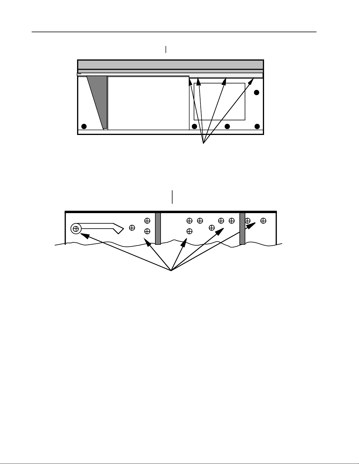
Step 3. Remove the screws that mount the control panel assembly to the front of the main
chassis. (Refer to Fig. 6-2)
Step 6. Remove the screws that mount the control panel assembly to the front of the main
chassis. These screws are accessed from the inside of the main chassis. (figure 6-3)
Step 7. Remove the cables from the LCD & Keypad.
Step 8. Replace control panel assembly in reverse order of removal.
PrePRESS Solutions CONFIDENTIAL
6-3November 1994
Page 42
TP8250
PantherPro Image Recorder
CONTROL PANEL ASSEMBLY
MAIN
CHASSIS
MOUNTING SCREW LOCATIONS
Control Panel Assembly Mounting Screw Locations
Figure 6-2
CONTROL PANEL ASSEMBLY
MAIN CHASSIS
MOUNTING SCREW LOCATIONS
Control Panel Assembly Internal Mounting Screw Locations
Figure 6-3
6-1.H Filter Access Panel
Step 1. Lift filter access panel up and away from unit to remove. (figure 6-1 H)
Step 2. Replace filter access panel in reverse order of removal.
6-2 E. M. I. Shield
Step 1. Remove front panel (figure 6-1.A).
Step 2. Remove the 8 screws securing the E. M. I. shield to the chassis.
Step 3. Replace E. M. I. shield in reverse order of removal.
6-4 November 1994
PrePRESS SOLUTIONS CONFIDENTIAL
Page 43

PantherPro Image Recorder
6-3 Keypad/LCD Assembly
Step 1. Remove the Control Panel Assembly (figure 6-1.G).
Step 2. Remove screws securing Keypad/LCD Assembly to Control Panel Assembly.
Step 3. Replace Keypad/LCD Assembly in reverse order of removal.
6-4 Electronics Assembly
Step 1. Remove the Electronics (figure 6-1.B) and Optics (figure 6-1.C) covers.
Step 2. Disconnect all the cables connected to the WSCB.
Step 3. Remove all page buffer modules (PBM) and PBM 's SCSI cable.
Step 4. Remove 5 mounting screws on the component side of the WCB and 6 mounting
screws holding the WCB's I/O panel to the rear cover.
Step 5. Carefully slide the WCB out through the rear panel
TP8250
Step 6. Replace in reverse order of removeal.
6-5 Fan Assembly
Step 1. Remove the Electronics Assembly (figure 6-6).
Step 2. Remove the Fan Assembly from the electronics assembly by removing the 4
mounting screws.
Step 3. Replace Fan(s) as required.
Step 4. Replace the Fan Assembly in reverse order of removal.
6-6 Power Supply Drawer
Step 1. Remove 7 screws securing power supply drawer to rear panel.
Step 2. Remove the wires from the AC and DC voltages terminal blocks. Note position of
wires or refer to Section 4.
Step 3. Remove the screws that mount the Power Supply to the drawer.
Step 4. Replace the Power Supply and other items in reverse order of removal. Refer to
Section 4 for power supply connections points if necessary.
Step 5. Adjust power supply voltages as detailed in Section 8-4.
PrePRESS Solutions CONFIDENTIAL
6-5November 1994
Page 44

TP8250
6-7 I/O Panel
Note: I/O Panel is part of WCB Assembly
6-8 Polygon Motor Assembly
Note: The motor spins several minutes after power has been turned off. Do not remove
polygon motor assembly until it has fully stopped.
Caution: The coating on the mirror surfaces is very delicate. Cleaning of the mirror
surfaces is not recommended. Use clean, dry air to blow any particles off of the
mirror surface.
Step 1. Remove the Electronics (figure 6-1.B), and Optics (figure 6-1C) Covers.
Step 2. Disconnect cable connecting the polygon and the polygon driver board.
Step 3. Remove the polygon motor assembly by removing the three large allen head
mounting screws.
PantherPro Image Recorder
Step 4. Replace the polygon motor assembly in reverse order of removal.
6-9 Laser Amplifier PCB
Step 1. Remove the Electronics (figure 6-1.B), Rear (figure 6-1.D), and Optics (figure 6-1C)
Covers.
Step 2. Remove cables connected to laser amp and polygon driver PCB's.
Step 3. Remove 5 mounting screws holding laser amp/polygon PCB bracket to chasis.
Step 4. Lift bracket out of the optical bed. Remove 4 mounting screws holding laser amp to
bracket.
Step 5. Replace the laser amp in the reverse order of removal.
6-10 Polygon Driver PCB
Step 1. Remove the Electronics (figure 6-1.B), Rear (figure 6-1.D), and Optics (figure 6-1C)
Covers.
Step 2. Remove cables connected to laser amp and polygon driver PCB's.
Step 3. Remove 5 mounting screws holding laser amp/polygon PCB bracket to chasis.
Step 4. Lift bracket out of the optical bed. Remove 4 mounting screws holding polygon
driver to bracket.
Step 5. Replace the polygon driver in the reverse order of removal.
6-6 November 1994
PrePRESS SOLUTIONS CONFIDENTIAL
Page 45
PantherPro Image Recorder
TP8250
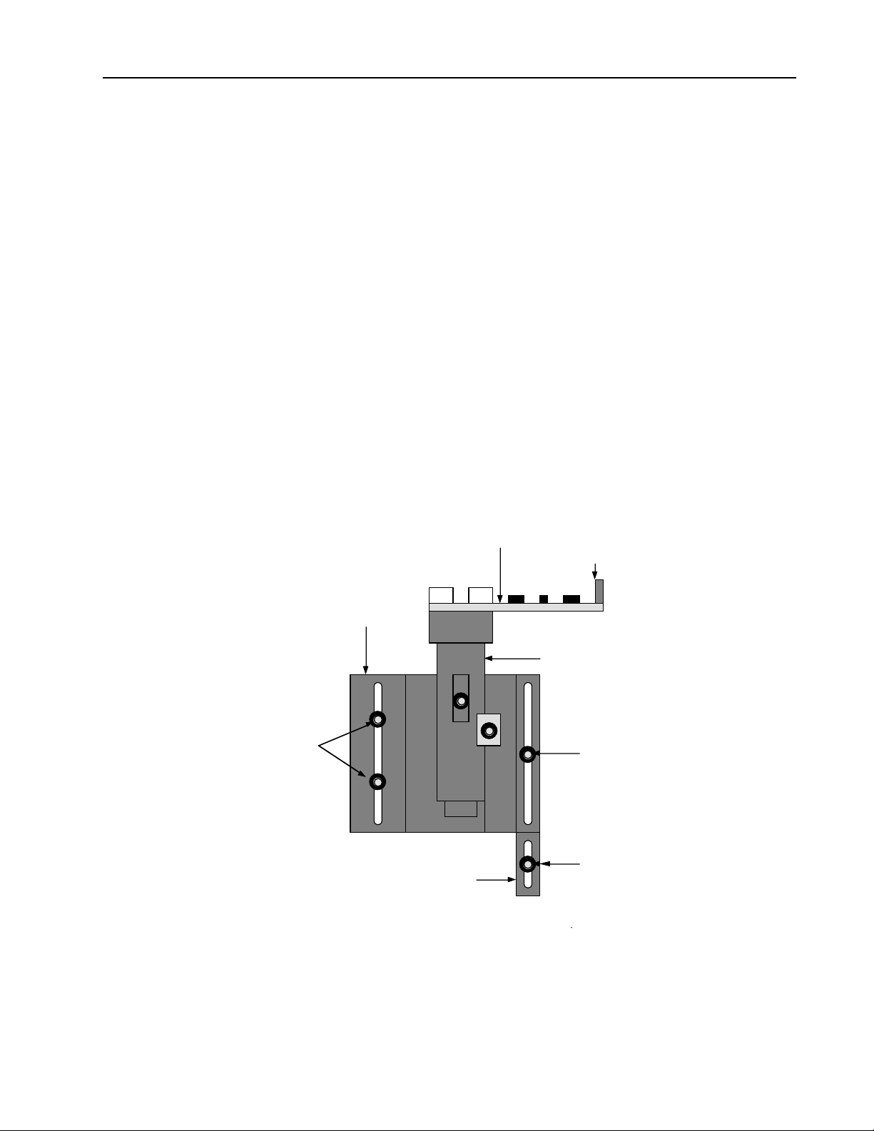
6-11 Laser Diode Assembly
(Refer to Figure figure 6-6)
Step 1. Remove the Electronics (figure 6-1.B), and Optics (figure 6-1C) Covers.
Step 2. Remove the laser diode assembly cover.
Step 3. Disconnect the cable from the laser driver pcb.
Step 4. Verify that laser diode assembly is positioned firmly against stop block.
Step 5. Loosen the 2 screws on the mounting clamp.
Step 6. Remove the laser diode assembly mounting screw.
Step 7. Carefully remove laser diode assembly. Be careful to not touch the scan lens.
Step 8. Replace the laser diode assembly in reverse order of removal. Position the laser
diode assembly firmly against the stop block before tightening the mounting screws.
MOUNTING
SCREWS
MOUNTING
CLAMP
STOP
BLOCK
LASER
DRIVER PCB
RIBBON CABLE
CONNECTOR
LASER DIODE
TUBE ASSEMBLY
MOUNTING
SCREW
MOUNTING
SCREW
Laser Diode Assembly
Figure 6-6
PrePRESS Solutions CONFIDENTIAL
6-7November 1994
Page 46
TP8250
PantherPro Image Recorder
6-12 Second Cylinder Lens Assembly
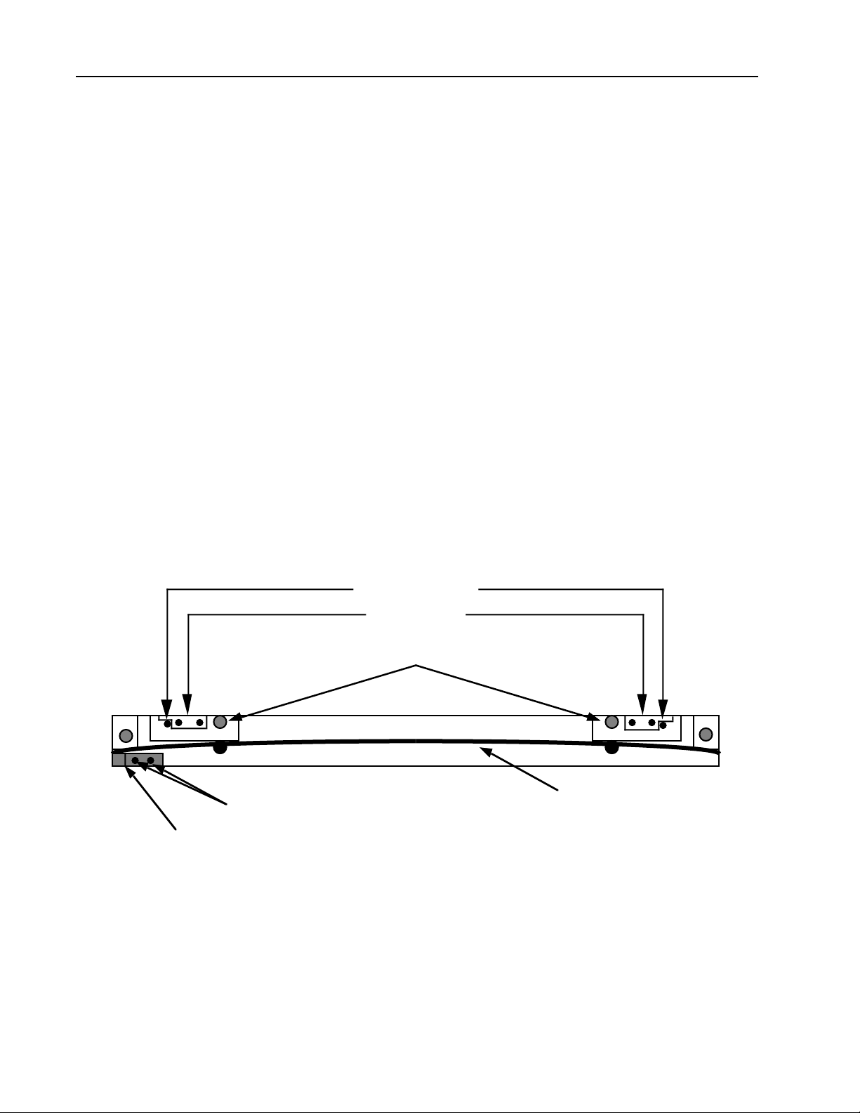
Refer to Figure 6-7
Step 1. Remove the Electronics (figure 6-1.B), Rear (figure 6-1.D), and Optics (figure 6-1C)
Covers.
Step 2. Remove the Suppy Cassette Door (figure 6-1.E).
Step 3. Remove the internal panel and supply cassette tray. Be careful when moving the
wires attached to the media out switch.
Step 4. Remove the cable from the start of line sensor.
Step 5. Loosen the 2 hex head bracket securing screws.
Step 6. Lift out second cylinder lens assembly.
Step 9. Carefully replace the second cylinder lens assembly in reverse order of removal.
Make sure that pin guides are securely against base casting pins.
LOCATOR PINS
PIN GUIDES
ASSEMBLY MOUNTING SCREWS
SECOND CYLINDER LENS
SOL MOUNTING SCREWS
START OF LINE ASSEMBLY
Second Cylinder Lens Start of Line Sensor Assembly
Figure 7
6-13 Start Of Line Sensor PCB
Step 1. Remove the Electronics (6-1.B), Rear (6-1.D), and Optics (6-1C) Covers.
6-8 November 1994
PrePRESS SOLUTIONS CONFIDENTIAL
Page 47

PantherPro Image Recorder
Step 2. Remove the Suppy Cassette Door (6-1.E).
Step 3. Remove the internal panel and supply cassette tray. Be careful when removing the
panel since there are wires attached to the bottem (media out switch wire).
Step 4. Remove the cable from the start of line sensor.
Step 5. Remove the 2 screws that mount the SOL Sensor to the bracket.
Step 6. Replace the SOL Sensor in reverse order of removal.
6-14 Paper Feed Gate Assembly
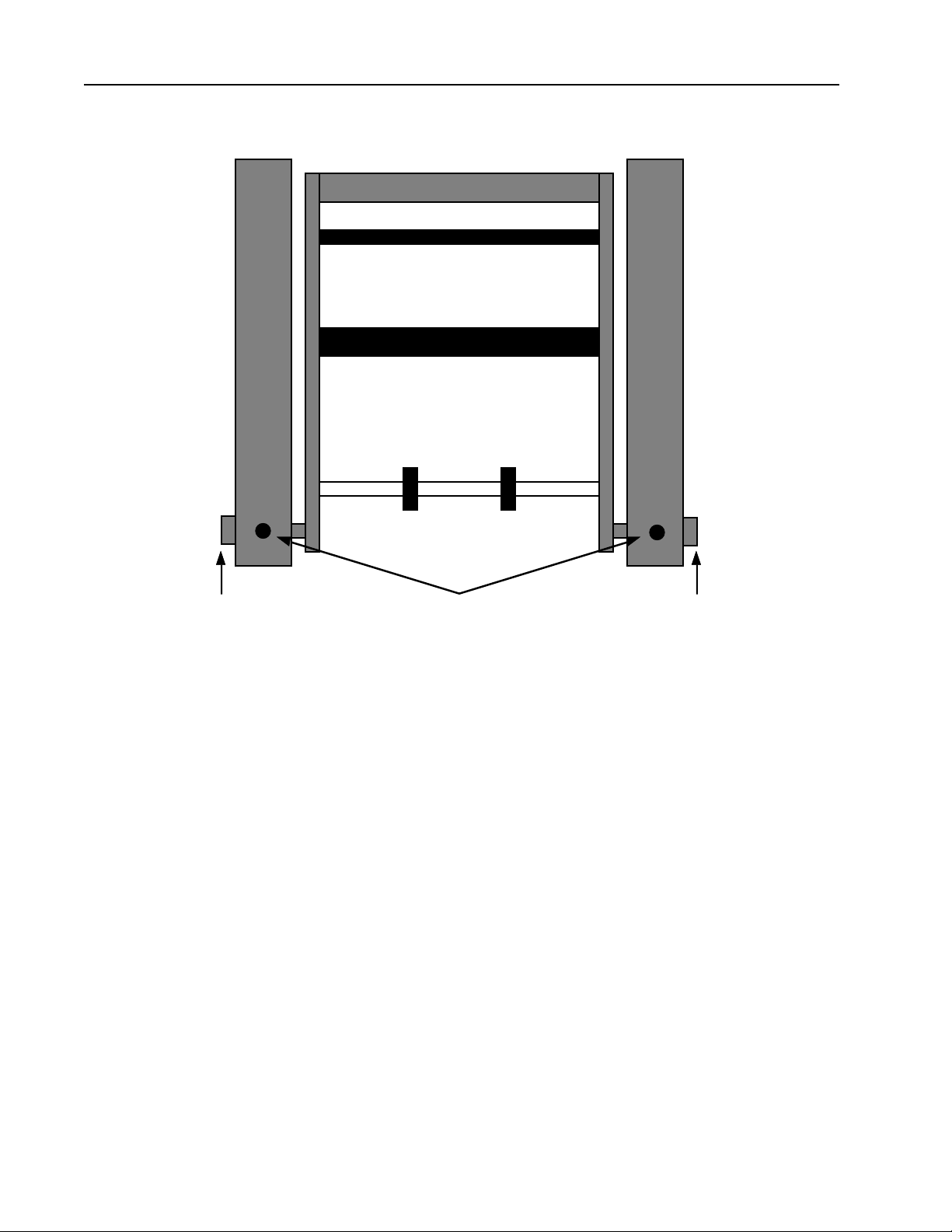
Refer to Figure 6-8
Step 1. Open supply and take up cassette access doors.
TP8250
Step 2. Loosen set screws that hold gate pins in position.
Step 3. Pull gate pins away from casting and gate assembly.
Step 4. Lift gate assembly to remove.
Step 5. Replace the gate assembly in reverse order of removal. Push gate pins in so that
there is no side to side movement of the gate. Also, make sure that the image roller is not
rubbing on the SOL detector.
PrePRESS Solutions CONFIDENTIAL
6-9November 1994
Page 48
TP8250
PantherPro Image Recorder
GATE ASSEMBLY
GATE PINSET SCREWSGATE PIN
Gate Assembly
Figure 6-8
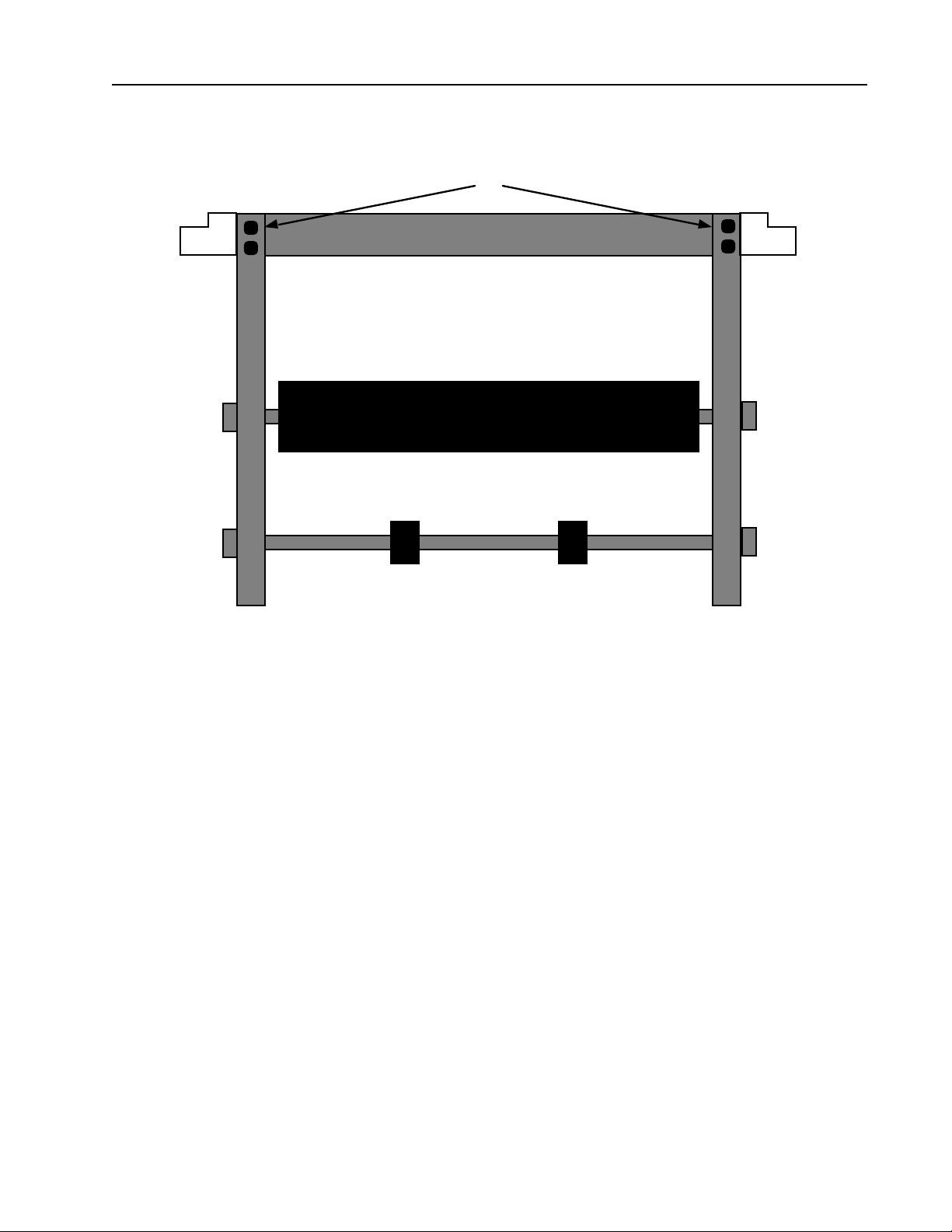
6-15 Gate Assembly Rollers
Refer to Figure 6-9
Step 1. Remove gate assembly.
Step 2. Remove from one side the allen head screws that mount the handle assembly to
the side plate.
Step 3. Remove mounting screws to remove desired roller.
Step 4. Replace the rollers and gate assembly in reverse order of removal. Push gate pins
in so that there is no side to side movement of the gate.
6-10 November 1994
PrePRESS SOLUTIONS CONFIDENTIAL
Page 49
PantherPro Image Recorder
TP8250
HANDLE MOUNTING SCREWS
IMAGING ROLLER
PRESSURE ROLLER
Gate Assembly Rollers
Figure 6-9
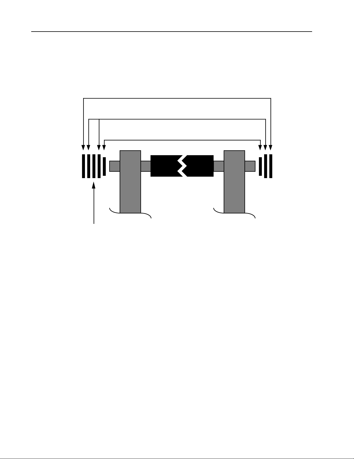
6-16 Metering Roller
Refer to Figure 6-10
Step 1. Open supply and take up cassette access doors.
Step 2. Remove rear cover.
Step 3. Remove the “E” ring, flat washer and bearing spacer from right side of roller shaft.
Step 4. Remove the “E” ring, two flat washers, spring washer and bearing spacer from left
side of roller shaft.
Step 5. Push bearing out and remove roller.
PrePRESS Solutions CONFIDENTIAL
6-11November 1994
Page 50
TP8250
Step 6. Replace the metering roller in reverse order of removal.
E RINGS
FLAT WASHERS
BEARING SPACERS
METERING ROLLER
PantherPro Image Recorder
SPRING WASHER
Metering Roller
Figure 6-10
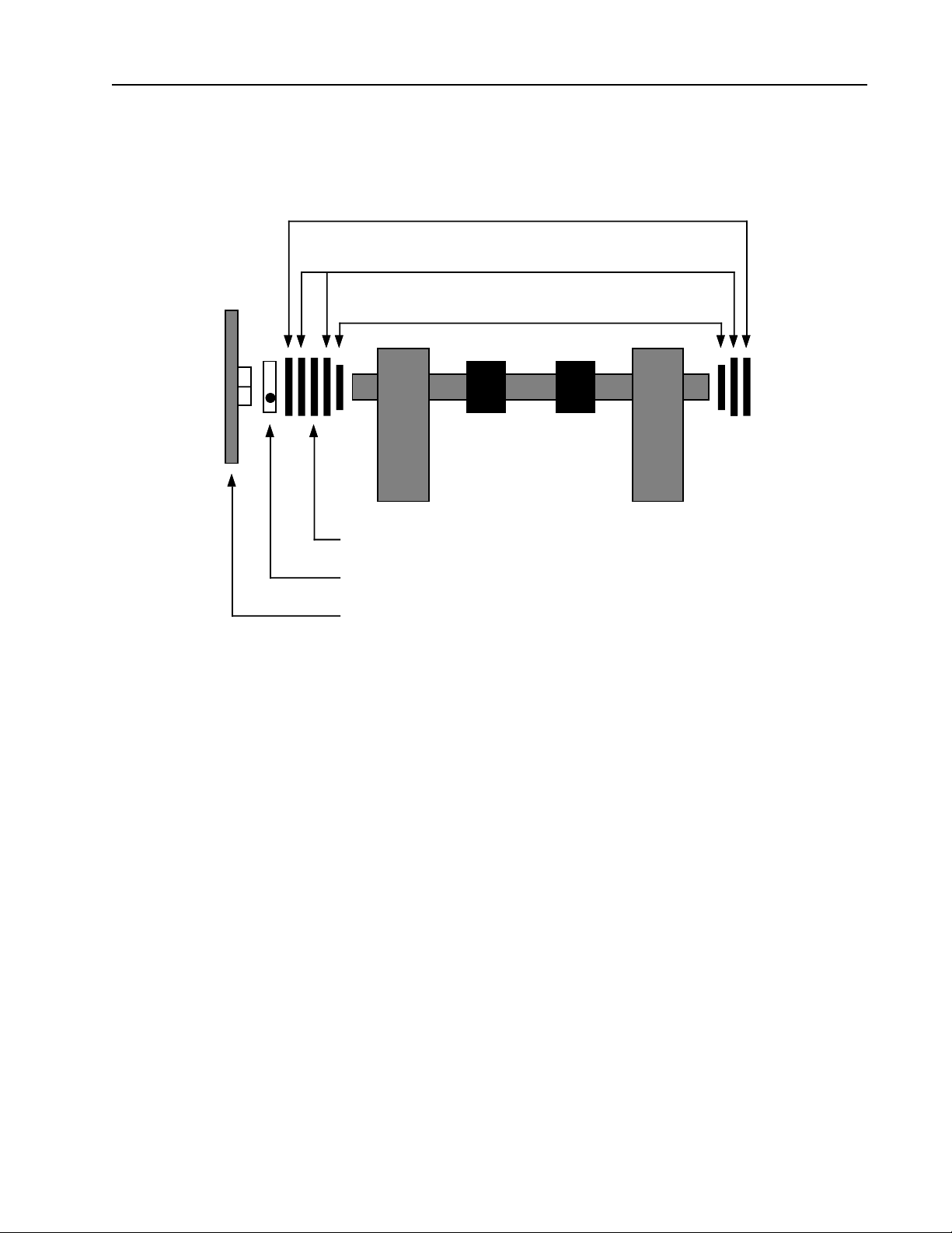
6-17 Drive Roller
Refer to Figure 6-11
Note: Removal of the drive roller or bearings requires that the main casting be removed from the chassis.
Step 1. Remove all machine covers and panels except for control panel.
Step 2. Remove screws that mount casting to chassis.
Step 3. Carefully lift chassis out and place on sturdy table with paper feed housing section
hanging over the edge.
Step 4. Remove the 6 screws that mount the paper feed take up housing to the casting,
6-12 November 1994
PrePRESS SOLUTIONS CONFIDENTIAL
Page 51
PantherPro Image Recorder
and remove housing.
TP8250
E RINGS
FLAT WASHERS
BEARING SPACERS
DRIVE ROLLER
SPRING WASHER
CLAMP
SPUR GEAR
Drive Roller
Figure 6-11
Step 5. Remove Gate Assembly and entire Knife Assembly.
Step 6. Remove the “E” ring, flat washer and bearing spacer from right side of drive roller
shaft.
Step 7. Loosen the spur gear clamp and remove spur gear.
Step 8. Remove the “E” ring, two flat washers, spring washer and bearing spacer from left
side of drive roller shaft.
Step 9. Push bearing out and remove drive roller.
Step 10. Replace the drive roller in reverse order of removal.
6-18 Knife Carriage Assembly
Step 1. Open supply and take up cassette access doors.
PrePRESS Solutions CONFIDENTIAL
6-13November 1994
Page 52
TP8250
PantherPro Image Recorder
Step 2. Remove rear cover.
Step 3. Remove carriage shaft left side mounting plate.
Step 4. Slide knife carriage assembly off shaft to remove.
Step 5. Replace the knife carriage shaft in reverse order of removal.
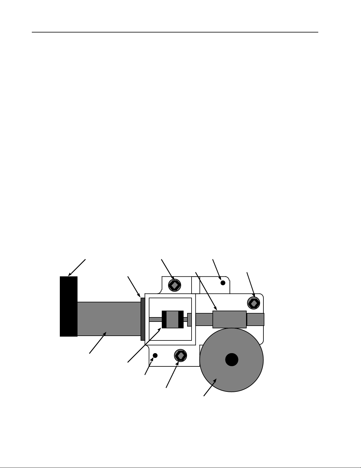
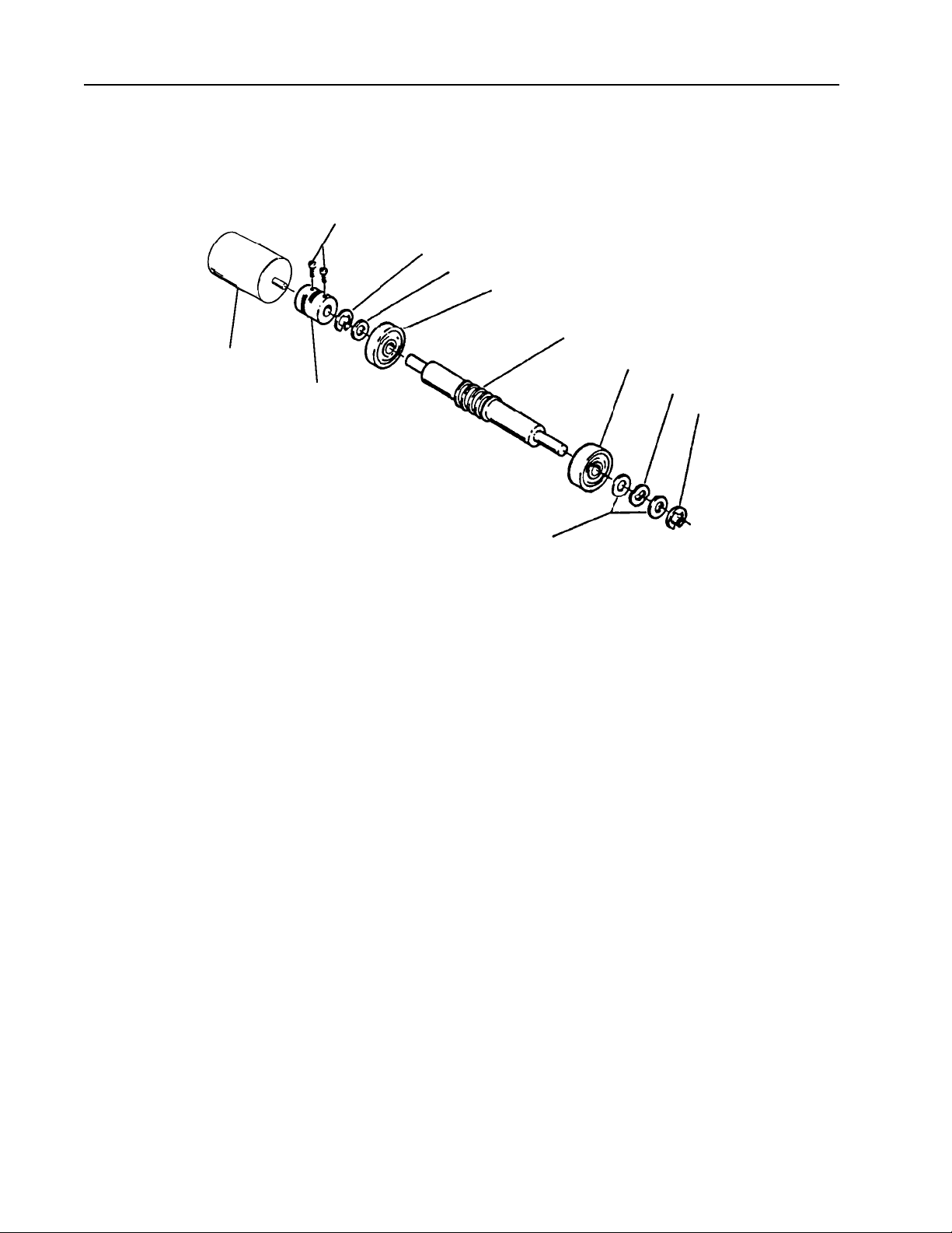
6-19 Servo Leading Motor and Gearbox Assembly
Refer to Figure 6-12
Step 1. Remove front cover.
Step 2. Remove gearbox cover panel.
Step 3. Disconnect connectors from servo motor and encoder.
Step 4. Remove the 3 allen head screws that mount the gearbox assembly to the main
casting.
Step 5. Carefully pull assembly out.
Step 6. Replace the servo leading motor and gearbox assembly in reverse order of re-
moval.
SERVO ENCODER
MOTOR MOUNTING PLATE
SERVO MOTOR
MOUNTING SCREW
COUPLING
LOCATOR PIN
LOCATOR PIN
WORM
MOUNTING SCREW
MOUNTING SCREW
SPUR GEAR
Servo Motor and Gearbox Assembly
Figure 6-12
6-14 November 1994
PrePRESS SOLUTIONS CONFIDENTIAL
Page 53

PantherPro Image Recorder
6-20 Servo Leading Motor
Step 1. Remove front cover.
Step 2. Remove gearbox cover panel.
Step 3. Disconnect connectors from servo motor and encoder.
Step 4. Remove the 3 allen head screws that mount the gearbox assembly to the main
casting.
Step 5. Carefully pull assembly out.
Step 6. Remove the screws the mount the servo motor to the assembly.
Step 7. Replace the servo leading motor in reverse order of removal.
6-21 Leading Spur Gear
Step 1. Open supply and take up cassette access doors.
TP8250
Step 2. Remove front cover.
Step 3. Loosen the allen head screw on the spur gear clamp.
Step 4. Slide the spur gear off the roller shaft.
Step 5. Replace the spur gear in reverse order of removal. Install spur gear with split hub
against “E” ring on drive roller shaft.
Step 6. Lubricate gear with grease (P/N 09-2382-0)
PrePRESS Solutions CONFIDENTIAL
6-15November 1994
Page 54
TP8250
PantherPro Image Recorder
COUPLING SCREWS
E RING
FLAT WASHER
BEARING
WORM
LEADING MOTOR
COUPLING
Leading Motor and Worm
6-22 Leading Worm
Refer to Figure 6-13
Step 1. Remove front cover.
Step 2. Remove gearbox cover panel.
BEARING
SPRING WASHER
E RING
FLAT WASHERS
Figure 6-13
Step 3. Remove gearbox assembly.
Step 4. Loosen the coupling screw on the worm side.
Step 5. Remove the leading motor and mounting plate.
Step 6. Remove the worm by removing the “E” ring and washer from the motor side of the
worm, and the “E” ring, spring washer, two flat washers and bearing from the other side.
Step 7. Replace the worm in reverse order of removal.
Step 8. Lubricate gear with grease (P/N 09-2382-0)
6-16 November 1994
PrePRESS SOLUTIONS CONFIDENTIAL
Page 55

PantherPro Image Recorder
TP8250
PrePRESS Solutions CONFIDENTIAL
6-17November 1994
Page 56

PantherPro Image Recorder TP8250
Section 7 Diagnostics
7-1 Overview
The PantherPro contains ROM resident diagnostics and disk resident diagnostics that can
be accessed both onsite and remotely through the debug port. Most of these diagnostics
can also be accessed through the keypad.
7-2 PROM Resident Diagnostics
The PROM resident diagnostics consists of three sections;
PROM Monitor - Provides interface to the diagnostics,manages non volatile param
eters, sniffs system configuration, interfaces to utilitiesand boots the main
application or other disk based programs.
level 1 Diagnostics - Power-up HSCB tests (memory, timers, uarts...)
level 2 Diagnostics - PBM/SCSI tests
7-2.1 Level 1 Power-up Test Sequence and Definition
The level1 diagnostics are tests designed to test the hardware that makes up the CPU
section of the HSCB. These diagnostics are used to verify the minimum hardware required
to have a functioning CPU. Once this hardware has passed the level1 tests the level2
diagnostics may be executed. Beolow is an example of the sucessful completion of level 1
diagnostics.
DIAGNOSTICS V1.0
-WCB CPU Power-on TestsDRAM Long Word Write/Read Test PASSED
DRAM Word Write/Read Test PASSED
DRAM Byte Write/Read Test PASSED
Loading Exception Vectors to DRAM COMPLETE
Verify DRAM Exception Vectors PASSED
EPROM checksum test PASSED
LCD Timer Test PASSED
UART Timer Test PASSED
SIO 2681 channel B test (modem) PASSED
Automatic startup... type ^U to abort
PrePRESS SOLUTIONS CONFIDENTIAL
7-1November 1994
Page 57

TP8250
7-2.2 PROM Monitor
The PROM Monitor provides interface to the diagnostics, manages non volatile parameters,
sniffs system configuration, interfaces to utilities and boots the main application or other
disk based programs.
After the level 1 test pass, the system will prompt the user to type <CNTRL> U to enter the
PROM Monitor. The Monitor prompt is "]". Typing an "H" at the prompt will display the help
screen. Most of the available options are either for engineering development or for factory
use only. The page buffer programs and level 2 diagnostics are for field use. The help
screen is as follows;
A - Autoload from SCSI
AI num - Set autoloader target ID to num
AS - Autoload from Sun
B - breakpoint
C - continue
D - Diagnostics options Menu
DU - Dump 68000 Register Set
FD - Display file directory
FE [file]- Execute file if given else ‘main_app’
FL [file]- Load file if given else ‘main_app’
FR file - Remove file
G [addr] - go
H - print this help message
N - single step
R - reset system and reboot power-on tests
RES - reset and restart the monitor
V - enable one interrupt
X - Debug Flag Editor
PantherPro Image Recorder
Typing a "D" will display the Diagnostics Options Menu (Level 2).
Typing "FD" displays the available programs on the Page Buffer Disks.
Typing "FE [hscb_diag or ropmdiag] will run the selected diagnostic.
7-2.3 Level 2 Diagnostics
The level2 diagnostics are made up of page buffer module and SCSI tests. These tests will
be performed on all installed page buffer modules during power up if the level 2 diagnostics
are enabled. During the interactive mode, selected or all diagnostics can be performed on
individual page buffer modules. These tests can also be configured to test all installed
page buffer modules in this mode.
Typing "D" at the Monitor prompt will display the following menu;
7-2 November 1994
PrePRESS SOLUTIONS CONFIDENTIAL
Page 58

PantherPro Image Recorder TP8250
7-2.2 Level 2 Diagnostics Cont. Diagnostics Options Menu
A - Modify DEBUG Port Baud Rate: [2400 BAUD]
B - Enable/Disable Level 2 Diagnostics [Enabled]
C - Execute Level 2 Diagnostics
D - Display/Modify Control Register
E - Display/Modify System Debug Register
A - Modify DEBUG Port Baud Rate: [2400 BAUD] - Select A to change the Debug port
baud rate.
Communication Options Menu
DEBUG Port Baud Rate: [19200 BAUD]
A - 1200 Baud
B - 2400 Baud
C - 9600 Baud
D - 19200 Baud
Q - Quit After Saving
B - Enable/Disable Level 2 Diagnostics [Enabled] - Select B to Enable/Disable the Level 2
diagnostics. It is enabled by default.
C - Execute Level 2 Diagnostics - Select C to enter the Level 2 diagnostics. At the
WCB>>prompt, type "test" to execute diagnostics.When level 2 is entered, the system
is sniffed and displays the current configuration (see example below);
WCB Diagnostic V1.0 R2
PBM 0 Installed | FES 0 .
PBM 1 Installed | FES 1 .
PBM 2 Installed | FES 2 .
PBM 3 . | FES 3 .
PBM 4 .
[TEST: pbmOpen - Reset and Init current PBM
[TEST: hSipWrRd - HostSiop- Write/Read ncr53c700 TEMP Reg Test
[TEST: dSipWrRd - DiskSiop- Write/Read ncr53c700 TEMP Reg Test
[TEST: hSipInt - HostSiop- NCR Interrupt test
[TEST: dSipInt - DiskSiop- NCR Interrupt test
[TEST: hSipIlp - HostSiop- Internal Loopback Test, CPU/DRAM-toNCR ]
[TEST: dSipIlp - DiskSiop- Internal Loopback Test, CPU/DRAM-toNCR ]
[TEST: dSipDrive - DiskSiop-to-PB Drive SCSI Block Write/Read Test
PrePRESS SOLUTIONS CONFIDENTIAL
7-3November 1994
Page 59

TP8250
7-2.2 Level 2 Cont.
PantherPro Image Recorder
Type test at the prompt to execute level 2 diags (see example below);
WCB>>test
[TEST: pbmOpen - Reset and Init current PBM
[TEST: hSipWrRd - HostSiop- Write/Read ncr53c700 TEMP Reg Test
[TEST: dSipWrRd - DiskSiop- Write/Read ncr53c700 TEMP Reg Test
[TEST: hSipInt - HostSiop- NCR Interrupt test
[TEST: dSipInt - DiskSiop- NCR Interrupt test
[TEST: hSipIlp - HostSiop- Internal Loopback Test, CPU/DRAM-toNCR ]
[TEST: dSipIlp - DiskSiop- Internal Loopback Test, CPU/DRAM-toNCR ]
[TEST: dSipDrive - DiskSiop-to-PB Drive SCSI Block Write/Read Test
[TEST: pbmzClose - Reset and Disable current PBM
WCB>>
D - Display/Modify Control Register - For development
E - Display/Modify System Debug Register - For development.
7-3 Disk Based Diagnostics
The disk based diagnostics are loaded automatically along with the system software. The
diagnostic programs are hscb_diag and ropmdiag. They are accessed through the debug
port (ropmdiag is available through the keypad, although the keypad version is not as
robust). When logged on with a terminal, the system will prompt you to type a <CNTL> U to
enter the PROM Monitor. At the prompt type "FD" to display the diagnostic programs available. To launch a program, type "fe hscb_diag or fe ropmdiag"
7-3.1 HSCB_DIAG
The HSCB_DIAG is used to test the page buffer modules as well as the drives. When the
program is loaded, the following is displayed;
]fe hscb_diag
PBM 0 Installed | FES 0 .
PBM 1 Installed | FES 1 .
PBM 2 Installed | FES 2 .
PBM 3 . | FES 3 .
PBM 4 .
[TEST: lcdram - LCD Display Ram Tests
[TEST: pbmOpen - Reset and Init current PBM
[TEST: hSipWrRd - HostSiop- Write/Read ncr53c700 TEMP Reg
[TEST: dSipWrRd - DiskSiop- Write/Read ncr53c700 TEMP Reg
[TEST: hSipSfifo - HostSiop- NCR SCSI Fifo Test
[TEST: dSipSfifo - DiskSiop- NCR SCSI Fifo Test
[TEST: hSipDma - HostSiop- NCR DMA Fifo Test
[TEST: dSipDma - DiskSiop- NCR DMA Fifo Test
[
7-4 November 1994
PrePRESS SOLUTIONS CONFIDENTIAL
Page 60

PantherPro Image Recorder TP8250
TEST: hSipInt - HostSiop- NCR Interrupt test
[TEST: dSipInt - DiskSiop- NCR Interrupt test
[TEST: hSipIlp - HostSiop- Internal Loopback Test, CPU/DRAM-toNCR ]
TEST: dSipIlp - DiskSiop- Internal Loopback Test, CPU/DRAM-toNCR ]
[TEST: hSipBrdma - HostSiop- NCR Dma Burst Write to CPU/DRAM
[TEST: dSipBrdma - DiskSiop- NCR Dma Burst Write to CPU/DRAM
[TEST: dSipPbRd - DiskSiop- NCR Dma Burst Read from PBM/DRAM
[TEST: dSipPbWr - DiskSiop- NCR Dma Burst Write to PBM/DRAM
[TEST: pbmDrive - Page Buffer Drive Selftest
[TEST: passSSM - HostSiop-to-PBM/DRAM SSM Transfer (ByPass)
[TEST: pB2ACpuScs - DiskSiop-to-CPU/Diag Reg. SCSI Transfer
(ByPass) ]
[TEST: pbmzClose - Reset and Disable current PBM
]hscb>>
Also available at the hscb command line are the following utilities;
scsiSniff Sniff - Scan Local PBM SCSI Bus
scsiInquiry Inquiry - SCSI Inquiry Command
Pbms Pbms <1st PBM> <last PBM> [-r] - Test multiple PBM and drives
7-3.2 ROPMDIAG
The ropmdiag is the recorder output module diagnostic. It tests the submodule of the hscb
that pertain to the recorder (video, tranport, etc.). When the ropmdiag is loaded, type test at
the ROPM> prompt. the following will be displayed;
ROPM> test
FAILED:0 PASSED:0 MFCLK
MFCLK Circuit Test
FAILED:0 PASSED:0 LLen-Reg
Line Length Register Test
FAILED:0 PASSED:0 Lead-Ctl
Paper Feed Test
MTRSTP Test
Paper Jam Detect Test
FAILED:0 PASSED:0 Facet-T/D
Facet Timer Test
Speed Detect Test
Search for STRTOK Test
Speed Detect (imaging mode) Test
Facet Decode (imaging mode) Test
0 errors this pass
PrePRESS SOLUTIONS CONFIDENTIAL
7-5November 1994
Page 61

TP8250
EOS Interrupt Test
FAILED:0 PASSED:0 Margin
Margin Reg/Counter Test
FAILED:0 PASSED:0 DPVM/FIFO
DPVM Word Counter Test
PIPEFULL Interrupt Test
X Counter Test
DPVM/Scan Line FIFO Data Test
ROPMDIAG Subtest
An additional set of utilities are available in the subtest directory. At the ROPM> prompt
type subtest to enter this area. Type a "?" to display the contents of subtest. To execute a
test, type a test name in the left column below at the prompt. The following tests are available;
ROPM> SubTest
ROPM SubTest>
DPVM-FIFO DPVM/Scan Line FIFO Data Test
DPVM-WCnt DPVM Word Counter Test
EOS-Intr EOS Interrupt Test
Facet-Timer Facet Timer Test
FDecode-Img Facet Decode (imaging mode) Test
Fill-DPVM Fill DPVM with pattern
Jam-Detect Paper Jam Detect Test
LLen-Reg Line Length Register Test
MargReg/Ctr Margin Reg/Counter Test
MFCLK MFCLK Circuit Test
MTRSTP MTRSTP Test
Paper-Feed Paper Feed Test
PFull-Intr PIPEFULL Interrupt Test
Spd-Detect Speed Detect Test
Spd-Det-Img Speed Detect (imaging mode) Test
Srch-STRTOK Search for STRTOK Test
Verify-DPVM Verify DPVM with pattern
XCount X Counter Test
Up Previous command level
Cutter Cutter Test
Interlock Interlock Switch Monitor
Keypad Keypad Test
LaserIntens Laser Intensity Reg/DAC Exerciser
LaserSystem Laser System Test
Leading Leading Motor Test
LDeadMan Leading Deadman Timer Test
OLPPort Online Processor Port Loopback Test
PolygonSpd Polygon Speed Range Test
PantherPro Image Recorder
7-6 November 1994
PrePRESS SOLUTIONS CONFIDENTIAL
Page 62

PantherPro Image Recorder TP8250
7-4 Keypad Diagnostics
Diagnostics and utilities can be accessed through the keypad. Level 2 tests, recorder
output module diagnostics, and the communication and SCSI utilities are available. If the
level 1 and level 2 diagnostics pass successfully, the following screen is displayed;
Monitor V1.6
Mon Jun 6 10:57:45 EDT 1994
Startup: OK
Channel A 9600 Baud
ROM ID 940606-10:57
Automatic Startup . . Online to abort
Press the ' ! ' key to enter keypad diagnostics. After the ' ! ' key is pressed, the following
screen is displayed;
Monitor V1.6 Main Menu
F1 - Level 2 Tests
F2 - Disk based utilities
F3 - Communication Utilities
F4 - SCSI Downloader
F1 F2 F3 F4 Exit
7-4.1 Level 2 Tests
Pressing F1 displays the following screen;
Monitor V1.6 Level 2 Diagnostics Menu
F1 - Run Level 2 Diagnostics
F2 - Set Level 2 mode [enabled]
F1 F2 Exit
Pressing F1 re-runs the level 2 diagnostics. Pressing F2 toggles between enabling and disabling level 2 diagnostics.
PrePRESS SOLUTIONS CONFIDENTIAL
7-7November 1994
Page 63

TP8250
7-4.2 Disk based Utilities
Pressing F2 displays the following screen;
Monitor V1.6 Utilities Menu
F1 - Recorder Output Module Diagnostics
F1 Exit
Pressing F1 displays the following screen;
ROPM Diagnostic Main Menu
F1 - Run ROPM Tests
F2 - Run ROPM Tests Continuously
F3 - Recorder Tests
F4 - Options
PantherPro Image Recorder
F1 F2 F3 F4 Exit
F1 and F2 run the ROM tests. Pressing F3 displays the following screen;
Tests Menu 1 of 3
F1 - Cutter Tests
F2 - Interlock Switch Monitor
F3 - Keypad Test
F1 F2 F3 More Exit
Pressing ' more ' displays the following screen;
Tests Menu 2 of 3
F1 - Laser Intensity Reg/DAC Excersiser
F2 - Laser Systems Test
F3 - Leading Motor Drive Test
F1 F2 F3 More Exit
7-8 November 1994
PrePRESS SOLUTIONS CONFIDENTIAL
Page 64

PantherPro Image Recorder TP8250
7-4.2 Disk based Utilities Cont.
Tests Menu 3 of 3
F1 - Online Processor Loopback Test
F2 - Polygon Speed Range Test
F1 F2 Exit
The F1 option requires a loopback plug on the OLP port.
Pressing F4 of the ROPM Diagnostic Main Menu displays the following screen;
ROPM Diagnostic Options Menu
F1 - Clear Test Statistics
F2 - Abort on Error [ on / off ]
F3 - Summery of Test Statistics
F1 F2 F3 Exit
7-4.3 Communication Utilities
Pressing F3 of the Monitor Main Menu displays the following;
Monitor V1.6 Communications Menu
F1 - External Communication Diagnostic Test
F2 - Set Channel A (debug) [ 9600 baud ]
F1 F2 Exit
The F1 option requires an external loopback plug on the debug port. Pressing F2 toggles
between the available baud rates.
PrePRESS SOLUTIONS CONFIDENTIAL
7-9November 1994
Page 65

TP8250
7-4.4 SCSI Downloader Utilities
Pressing F3 of the Monitor Main Menu displays the following;
Monitor V1.6 Communications Menu
F1 - External Communication Diagnostic Test
F2 - Set Channel A (debug) [ 9600 baud ]
F1 F2 Exit
The F1 option requires an external loopback plug on the debug port. Pressing F2 toggles
between the available baud rates.
PantherPro Image Recorder
7-10 November 1994
PrePRESS SOLUTIONS CONFIDENTIAL
Page 66

PantherPro Image Recorder TP8250
Section 8 Reference/Adjustments
DANGER - Invisible laser radiation when the top cover is open and interlock defeated. Avoid direct exposure to beam.
CAUTION - Use of controls or adjustments or performance of procedures other than
those specified herein may result in hazardous radiation exposure.
NOTE - Maintain all Anti-Static procedures while performing removal/replacement
procedures on pc boards.
8-1 Jumpers, LED’s, and Switches Reference
The following details the switch settings, LED’s, and jumpers found on the PC boards.
High Speed Control Board
LED's:
LOCK - Indicates that the polygon driver has locked the polygon speed. This should always
be lit when the polygon is spun up.
LO/OK/HI - These three indicate polygon speed is lo, ok, or hi. They are updated every
scan line. When the polygon is spun up, OK should be lit.
STOK - Start pulses that are generated when the laser sweeps across the SOL sensor is
found by the laser amp PCB either in normal imaging or when switch 3 (PGEN) is closed.
VMWR - Indicates video writes into the dual ported video memory to the scan line FIFO.
This LED is not brightly lit.
VMRD - Indicates video reads from the dual port video memory to the scan line FIFO. This
LED is not brightly lit.
VID - Indicates actual video data. This LED is lit during the exposed parts of an image
(laser on). Note the sample / hold and enhance video activity light is lit dimly during an all
white image.
PrePRESS Solutions CONFIDENTIAL
8-1November 1994
Page 67

TP8250
POLY ERR - Indicates a polygon error condition. This happens only during imaging (page
enable on); the LED is kept on until the start of the next image. This error is caused by loss
of lock or by loss of speed OK, however briefly, during an image.
FIFO MT - Indicates a FIFO empty error condition. This happens only during imaging (page
enable on); the LED is kept on until the start of the next image. This error is caused when a
video read from the scan line FIFO is attempted and the FIFO is already empty.
WCB Switches:
Switch 1 & 2 - They are used for factory diagnostic testing. They should be in the OFF
position.
Switch 4 - Quad switch sw4 is comprised of 4 switches, switch 1 through 4, left to right.
These switches should be left in the open position for normal operation.
Switch 1 - PGEN - Sets page enable, allowing start pulses to be found. Provided the
polygon speed is OK, the laser will do the normal functions of sample / hold and
enhance, finding start pulses. If the light path is interrupted (SOL blocked) the en
hance laser power is kept on for about 93% of the time, searching in vain for a start
pulse. This provides a simple means of checking or adjusting the enhance laser
power level.
PantherPro Image Recorder
Switch 2 - SHOLD - Forces Sample/ Hold on for laser calibration. This switch closes
the sample / hold loop by forcing video ' 1's' pixels and sample / hold on, continuously. This
provides a simple means of checking or adjusting the 'imaging' laser power level.
Switch 3 - POLYSW - Spins up Polygon independent of software, uses purely hardware
generated signals.
Switch 4 - POLYTYPE - Tells software the polygon type (on=Lincoln, off=Copal). Not implemented at this time.
Jumpers:
Front-end Connect Jumpers
JP1 - FES0 Connect Ground - Install jumper if SCSI port/cable connected to J10 does not
have a ground on Pin 40.
JP2 - FES0 Connect Ground - Install jumper if SCSI port/cable connected to J11 does not
have a ground on pin 15.
JP3 - FES1 Connect Ground - Install jumper if SCSI port/cableconnected to J8 does not
8-2 November 1994
PrePRESS SOLUTIONS CONFIDENTIAL
Page 68

PantherPro Image Recorder TP8250
have a ground on pin 40.
JP4 - FES1 Connect Ground - Install jumper if SCSI port/cable connected to J9 does not
have a ground on pin 15.
JP5 - FES2 Connect Ground - Install Jumper if SCSI port/cable connected to J6 does not
have a ground on pin 40.
JP6 - FES2 Connect Ground - Install Jumper if SCSI port/cable connected to J7 does not
have a ground on pin 15.
JP7 - FES3 Connect Ground - Install jumper if SCSI port/cable connected to J4 have a
ground connected on pin 40.
JP8 - FES3 Connect Ground - Install jumper if SCSI port/cable connected to J5 does not
have a ground connected on pin 15.
WCB EPROM Jumpers:
JP9 - 10 EPROM Address Jumpers - Default etch connects pin 1 and 2 together. This
jumper will not change. JP9 connects address bit 18 to EPROM and JP10 connects bit 19
to EPROM.
WCB LCD Jumpers:
JP33 - LCD Inverter Power - Default etch pins 1 and 2. 1 and 2 provide +5Vdc to LCD
inverter.
JP34 - LCD frame Ground Connection - Default etch provides logic ground to LCD Frame
ground.
JP35 - LCD Character Size - Default etch pins 2 and 3. 1 and 2 provides 6 by 8 character
size, and pins 2 and 3 provides 8 by 8 character size.
Page buffer Module Jumpers:
JP11 - JP26 On HSCB (Page Buffer Module 0) are connected by default in etch to bypass
the 3210 compression chip.
JP27 - JP32 On HSCB (Page Buffer Module 0) 1 and 2 jumped to bypass the 3210 compression chip.
JP110 - JP125 On Page Buffer Modules (1 - 4) are connected by default in etch to bypass
the 3210 compression chip.
PrePRESS Solutions CONFIDENTIAL
8-3November 1994
Page 69

TP8250
Page Buffer Module LED's
On the HSCB, the led's are D11 & D12. On the Page Buffer Module, the LED's are D12 &
D13.
1 2 3 4 5 6 7 8
D11:HSCB D12:HSCB
D12:PBM D13:PBM
1. HGNT - The host SIOP is a 68000 bus master
2. DGNT - The disk SIOP is a 68000 bus master
3. IMG - The Page Buffer Module to image
PantherPro Image Recorder
4. DMEM - The local Page Buffer Module DRAM is being accessed
5. CPRS - The Page Buffe Module is selected to accept input data (compression path
enabled)
6. BXCV - Data is moving from port B of the 3210 to local DRAM (compression mode) or
data is moving from the disk SIOP to port B of the 3210 (decompression mode)
7. DA - Video datra is being moved into port A (compression) or video data is being output
(decompression)
8. DB - Video data is being moved into local DRAM (compression) or compressed data is
being sent to the 3210 (decompression)
7-2 High Speed Laser Amp
7.5V Adjustment
1. Make sure power is off. Center pots R22 and R 28
2. Connect only J1 and J2(make sure J3 is empty)
3. Attach voltmeter between TP1 and GND
4. Adjust R22 till you get a reading of 7.5V
8-4 November 1994
PrePRESS SOLUTIONS CONFIDENTIAL
Page 70
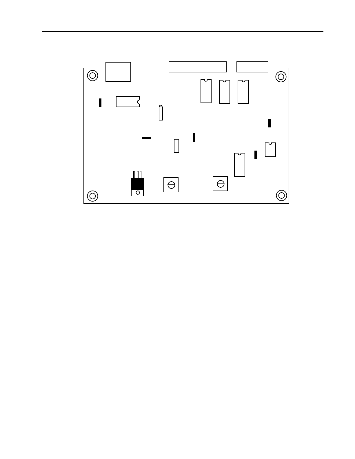
PantherPro Image Recorder TP8250
GND TP1
J1
U1
TP1
7.5V ADJUST
D2
R22
JP1
J2
U2
GND TP3
OFFSET ADJUST
U3 U4
R28
U6
J3
TP 2
1993 TEGRA, INC.
High Speed Laser Amp
500-008599-000
GND TP2
U7
REV B
7-3 Voltage Offset Adjustment
1. Make sure power is off. Remove JP1.
2. Attach meter to TP2.
3. On HSCB, turn on SHOLD switch.
4. Turn power on. Adjust R28 till you get a reading of 0.0V.
5. Turn power off. Reinstall JP1.
PrePRESS Solutions CONFIDENTIAL
8-5November 1994
Page 71

PantherPro Image Recorder TP8250
Section 9 Parts Listing
explanatory
General
This illustrated Parts Catalog has been
prepared to assist in identification of
parts which may require replacement as
a result of wear, damage or loss.
Parts Groups
A group shows a main physical subassembly. Each group comprises an
itemized illustration and a list of the
parts shown in the illustration.
Key
Every part or assembly listed has a key
number which corresponds to the illustration. The key number for an assembly
will appear in the illustration in a circle
close to the appropriate parts.
A suffix (A to Z, with the exception of I
and O) may be added to the key number, where necessary, for the following
reasons:
1. The key indicates parts which are
identical as far as installation and
function are concerned, but which
differ in part number, e.g. motors for
different voltages (also relays, solenoids, etc.)
Part Number
The full part number must always be
used when ordering parts.
Description
This column includes the name of the
parts and possibly one or more of the
following:
1. up to machine no. xxxx
This part is only used in machines up
to the stated serial number
2. from machine no. xxxx
This part can only be used in machines with quoted serial number or
a higher one.
All parts which require permanent riveting, welding, or assembly in jigs or
fixtures will be furnished assembled.
When the description is indented it is an
indication of the assembly level of the
part.
Quantity
The column quantity (Qty) shows the
quantity of each part as included in the
next larger assembly.
2. For non-interchangeable parts, the
new style part is identified by a new
line with the old key number (with
suffix), followed by the new part
number, description, and quantity.
PrePRESS SOLUTIONS CONFIDENTIAL
Special notes
If an asterisk (*) appears at the end of
the description column, reference is
made at the end of the group listing.
9-1November1994
Page 72
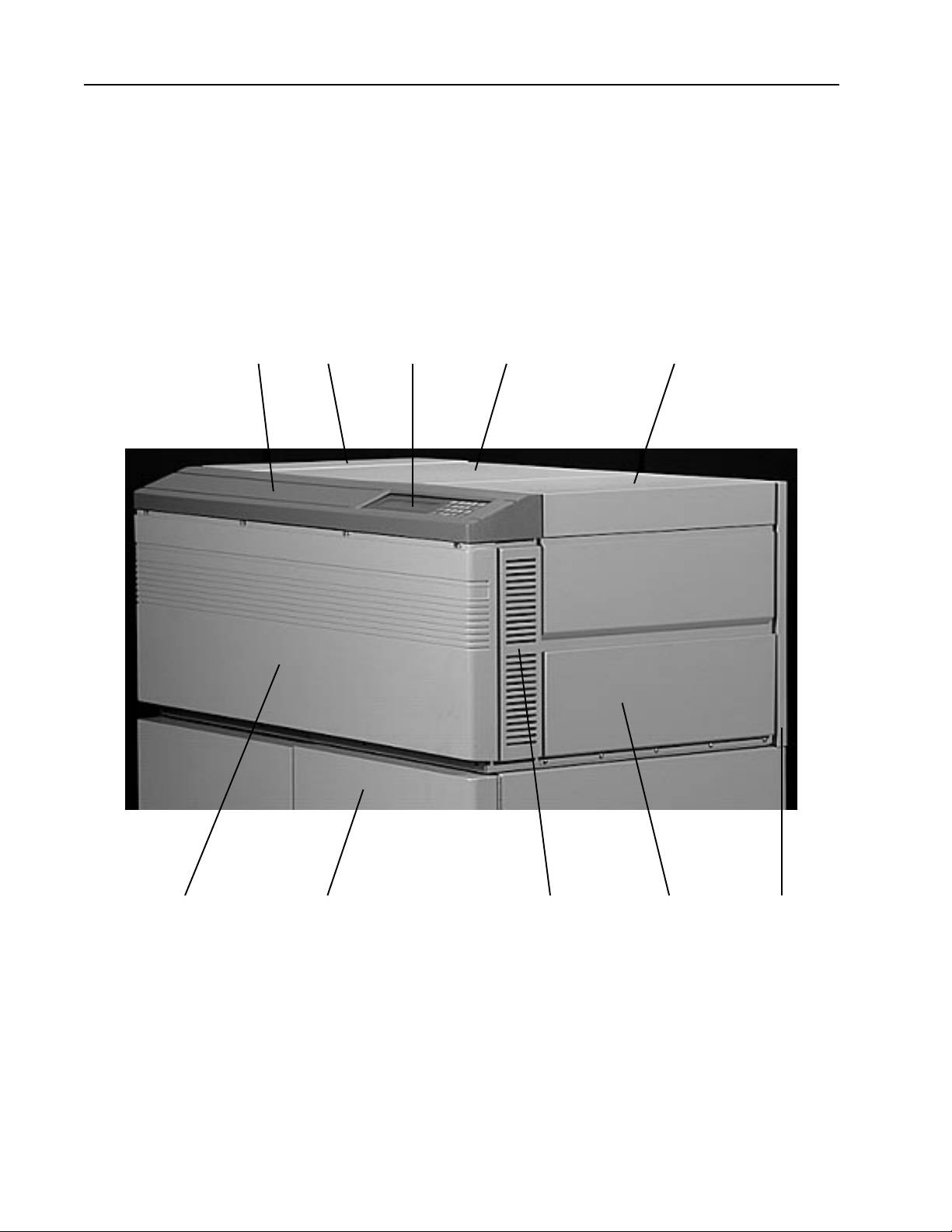
TP8250
Group 1 Case and Covers Front View
1 3 6 4 5
PantherPro Image Recorder
2 7 8 9 10
9-2 November1994
PrePRESS SOLUTIONS CONFIDENTIAL
Page 73

PantherPro Image Recorder TP8250
Group 1 Case and Covers Front View
Key Part Number Description Qty.
1 225 005056 000 Cover, Control Panel 1
2 200 005057 000 Cover, Front 1
3 200 005261 000 Cover, Electronics 1
4 200 005264 000 Cover, Optics 1
5 200 005263 000 Cover, Supply Cassette 1
5A 201 006466 000 Stay Arm, Cover 1
5B 202 005276 000 Hinge Shaft 1
5C 250 006300 000 Shoulder screw, 8-32 x 5/16" 1
5D 250 004415 000 Shoulder screw, 8-32 x 1/4" 1
5E 255 006301 000 Shoulder Washer, Nylon #10 2
5F 44-3357-0 Magnet, Switch Activator 2
5G 540 007088 000 Interlock Switch 2
6 505 008093 001 Keypad/LCD/Bkt Assy. 1
6A 460 007273 000 Keypad 1
6B 505 008088 001 LCD 1
6C 540 008080 000 Cable, LCD to Inverter PCB 1
6D 540 008081 000 Cable, LCD to HSCB 1
6E 540 008086 000 Cable, Keypad to HSCB 1
7 505 006688 000 Cabinet Stand Assembly 1
8 201 005268 000 Filter Panel 2
9 200 005262 000 Access Door, Take-up Cassette 1
9A 291 005321 000 Cable, Door Limit 1
9B 290 006708 000 Magnetic Catch 2
10 201 006651 000 Rear Cover
PrePRESS SOLUTIONS CONFIDENTIAL
9-3November1994
Page 74
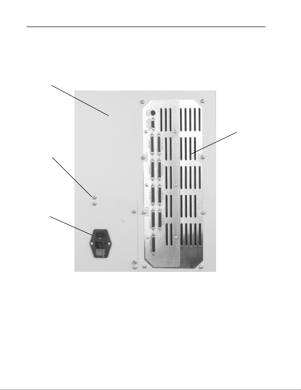
TP8250
Group 1A Case and Covers Rear View - I/O Panel
1
2
PantherPro Image Recorder
3
4
9-4 November1994
PrePRESS SOLUTIONS CONFIDENTIAL
Page 75

PantherPro Image Recorder TP8250
Group 1A Case and Covers Rear View - I/O Panel
Key Part Number Description Qty.
1 201 006651 000 Cover, Rear 1
2 250 000840 000 Screw, P.H. 8-23 X 3/8" A/R
3 201 008703000 I/O Panel 1
4 505 007599 000 Power/Switch Receptacle 1
4A 43-3360-0 Fuse, 4 Amp 1
4B 30-3670-0 Fuse, 2 Amp 1
5 356 003671 000 Power Cord, US 110V 1
6 250 000650 000 Screw, 4-40 x 1/2" 2
PrePRESS SOLUTIONS CONFIDENTIAL
9-5November1994
Page 76
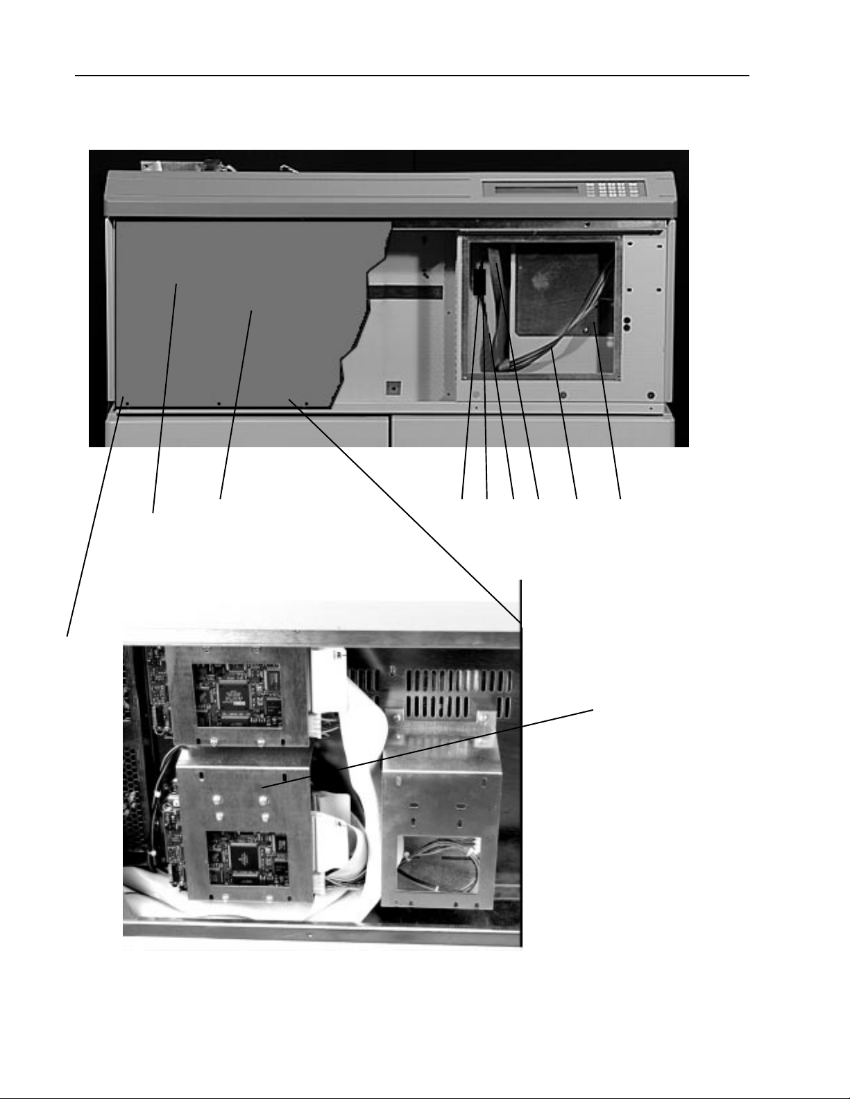
TP8250
Group 2 Front Components
PantherPro Image Recorder
8
1 2 3 4 5 6 7
8 - 12
9-6 November1994
PrePRESS SOLUTIONS CONFIDENTIAL
Page 77

PantherPro Image Recorder TP8250
Group 2 Front Components
Key Part Number Description Qty.
1 201 007161 000 Cover Shield, E. M. I. 1
2 500 007547 001 LCD Inverter PCB Assembly 1
3 540 008080 000 Cable, LCD Inverter to LCD 1
4 540 008082 000 Cable, Beeper/LCD Inverter to HSCB 1
5 540 008081 000 Cable, LCD to HSCB 1
6 540 008086 000 Cable, Keypad to HSCB` 1
7 201 005278 000 Cover Panel, Leading Motor Access 1
8 799 008264 000 540MB Page Buffer Disk Drive 1
9 505 008826 000 1 GB Page Buffer Disk Drive 1
10 505 008411 000 Dual 240 MB Page Buffers 1
11 505 008412 000 Dual 540 MB Page Buffers 1
12 735 008826 000 Dual 1 GB Page Buffers 1
PrePRESS SOLUTIONS CONFIDENTIAL
9-7November1994
Page 78
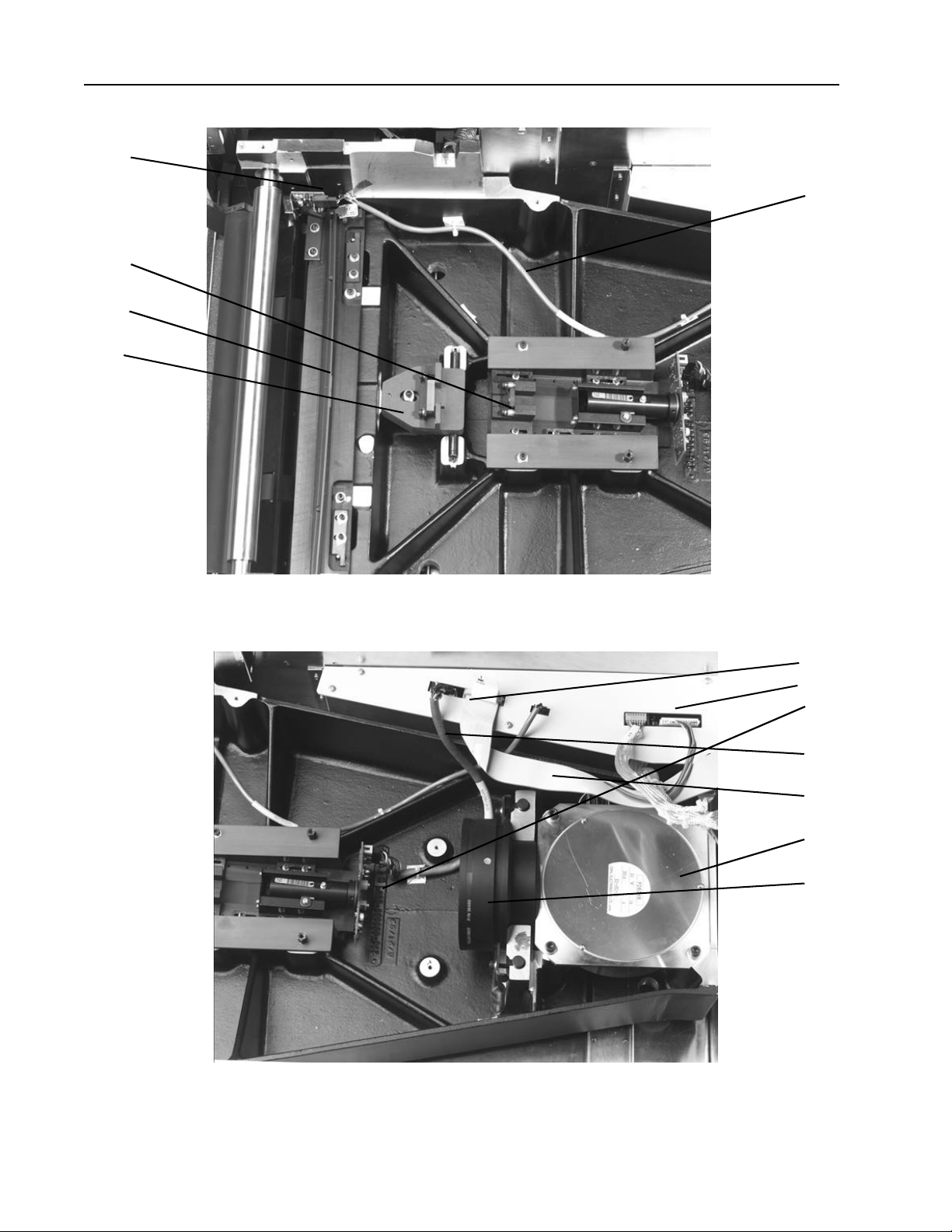
TP8250
3
9
10
11
PantherPro Image Recorder
5
1
7A
2
4
6
7
8
9-8 November1994
PrePRESS SOLUTIONS CONFIDENTIAL
Page 79

PantherPro Image Recorder TP8250
Group 3 - Optics
Key Part Number Description Qty.
1 500 008599 000 Laser Amp 1
2 505 008719 000 Assy., Laser / Laser Driver 1
3 505 009118 000 Assy., SOL / SOL Driver 1
4 540 008919 000 Cable, LD to LA 1
5 540 008963 000 Cable, SOL to LA 1
6 540 008948 000 Cable, HSCB to LA 1
7 480 008899 000 Assy., Polygon * 1
7A Polygon Driver
*Includes polygon, polygon driver board and correction PAL
cannot be ordered separately
8 475 006458 001 Scan Lens 1
9 505 006455 001 Assy., 1st Cylindrical Lens 1
10 505 006454 001 Assy., 2nd Cylindrical Lens 1
11 505 005238 000 Assy., Beam Steering Mirror 1
PrePRESS SOLUTIONS CONFIDENTIAL
9-9November1994
Page 80
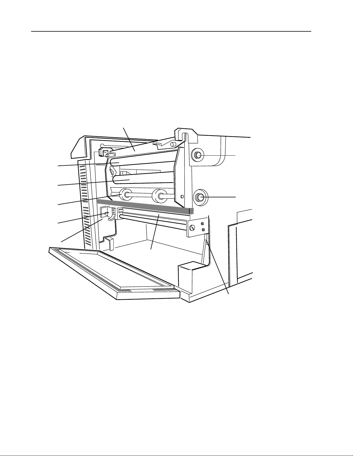
TP8250
Group 4 Paper Feed Transport
2
3
PantherPro Image Recorder
8
4
5
10
7
6
9
9-10 November1994
PrePRESS SOLUTIONS CONFIDENTIAL
Page 81

PantherPro Image Recorder TP8250
Group 4 Paper Feed Transport
Key Part Number Description Qty.
1 505 008930 000 Gate Assy 1
1A 201 006777 000 Latch, Left 1
1B 201 006777 001 Latch, Right 1
1C 201 007878 000 Shoulder Washer 2
1D 26-0121-0 Washer, Copper 2
1E 26-0672-0 Washer, Spring curved 2
1F 250 006779 000 Shoulder Screw, F. H. 2
1G 250 006305 000 Ball Plunger Screw 1
3 505 006452 000 Imaging Roller 1
4 505 005307 000 Pressure Roller Shaft Assy 1
4A 505 005308 000 Roller /Bearing 2
4B 202 005114 000 Shaft 1
4C 290 005111 000 “C” Retaining Ring 4
5 505 008378 000 Power Knife Carriage Assembly 1
5A 20-5169-0 Rotary Blade Assy 1
5B 20-5180-0 “O” Ring 1
6 201 005225 000 Stationary Blade 1
7 505 005296 000 Drive Roller/Shaft Assy 1
7A 210 005306 000 Bearing 2
8 505 006479 000 Metering Roller 1
8A 35-0257-0 Bearing 2
9 43-0733-0 Switch, Take-up Home 1
10 505 007823 000 Motor, Power Knife 1
10A 201 007739 000 Lead Screw 1
10B 201 007740 000 Mount Plate, Lead Screw, Motor End 1
10C 201 007741 000 Mount Plate, Lead Screw, Rght End 1
10D 210 003722 000 Rubber Grommet, End Limit 2
10E 540 007840 000 Switch and cable, Lft Limit 1
10F 540 007841 000 Switch and cable, Rgt Limit 1
PrePRESS SOLUTIONS CONFIDENTIAL
9-11November1994
Page 82
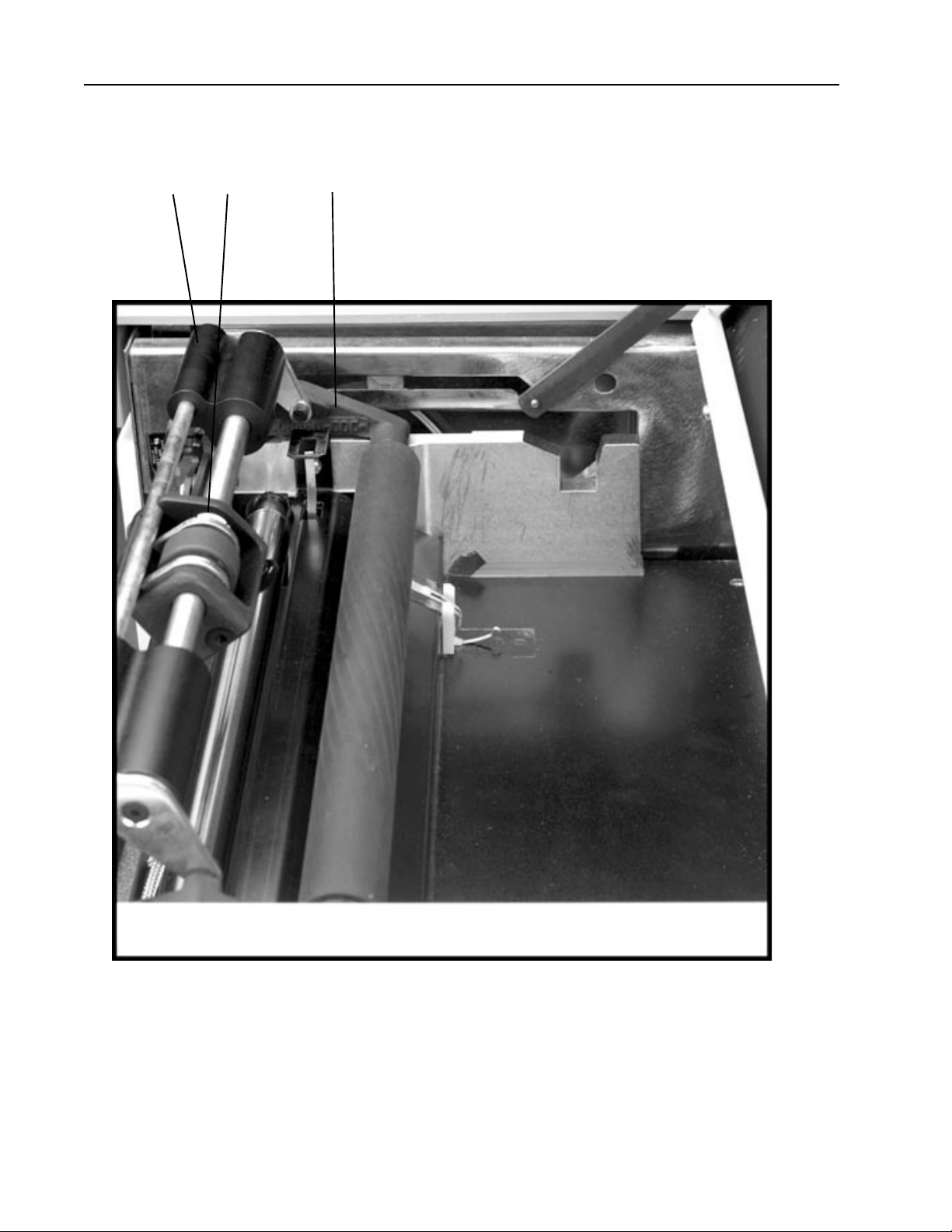
TP8250
PantherPro Image Recorder
2C 2A 1
9-12 November1994
PrePRESS SOLUTIONS CONFIDENTIAL
Page 83

PantherPro Image Recorder TP8250
Group 4A Paper Feed Transport
Key Part Number Description Qty.
1 350 006903 000 Paper Out Switch 1
2 505 008532 000 External Tensioner Module Assy A/R
2A 505 009099 000 ETM Brake Assy A/R
2B 735 009100 000 ETM Brake Assy w/Ballast A/R
2C 227 008991 000 Ballast A/R
PrePRESS SOLUTIONS CONFIDENTIAL
9-13November1994
Page 84
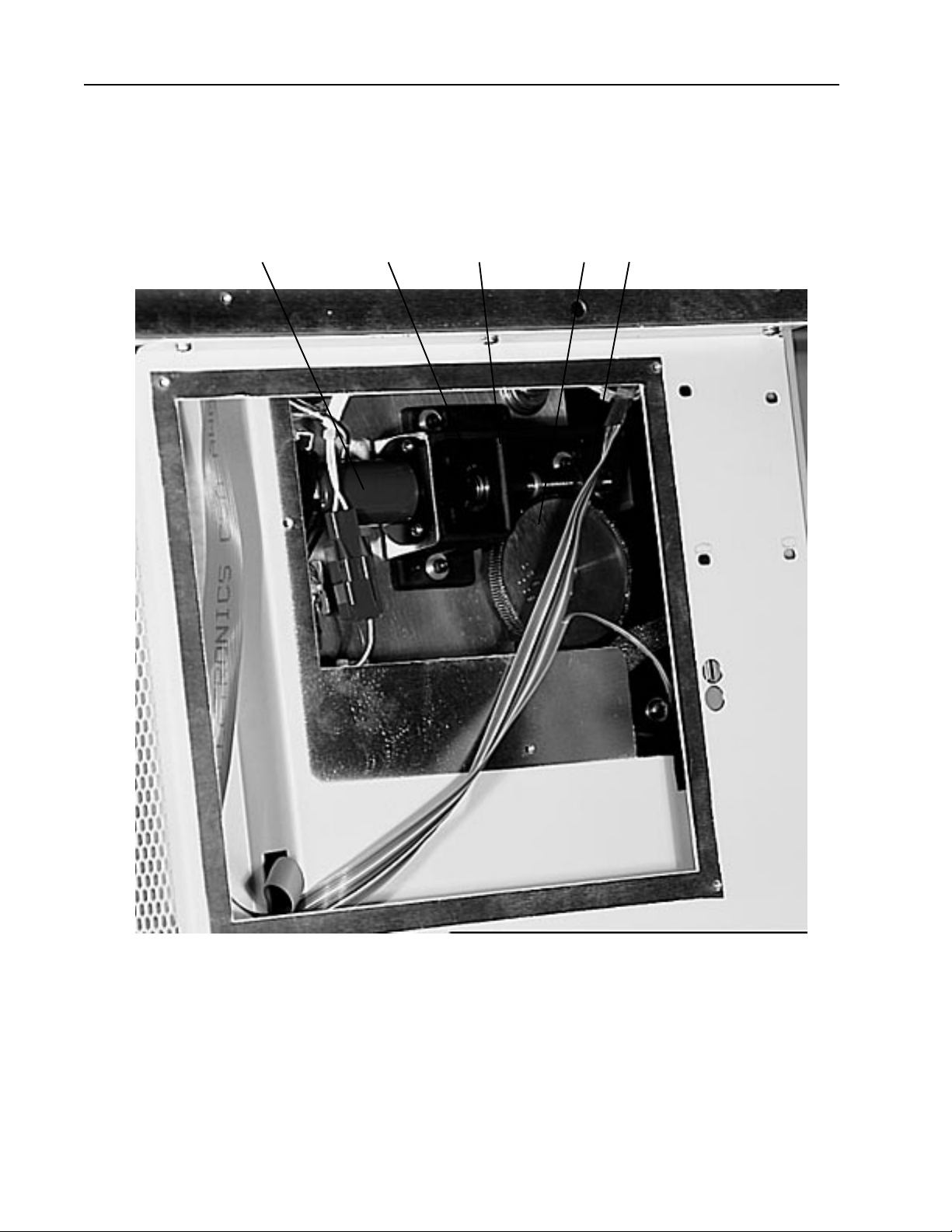
TP8250
Group 4A Paper Feed Drive
2 1 4 3 5
PantherPro Image Recorder
9-14 November1994
PrePRESS SOLUTIONS CONFIDENTIAL
Page 85

PantherPro Image Recorder TP8250
Group 4B Paper Feed Drive
Key Part Number Description Qty.
1 30-3037-0 Coupling 1
1A 35-0261-0 Bearing, Flanged 2
1B 202 005331 000 Worm Gear 1
2 44-1580-0 Motor/Encoder (Maxon) 1
2A 30-3408-0 Mounting Flange (Maxon) 1
2B 505 007874 000 Motor/Encoder (Pittman) 1
2C 201 007694 000 Mounting Flange (Pittman) 1
2D 21-0294-0 Screw, (Pittman Mtg.) 4
2E 21-1438-0 Screw, 2.5 x 6mm (Maxon Mtg) 3
2F 21-0615-0 Screw, 4-40 x 3/8 (Flange to Casting Mtg) 3
3 20-9343-0 Spur Gear 1
3A 20-9339-0 Gear Clamp 1
4 227 005087 000 Casting Housing 1
4A 26-0617-0 Shim Washer .005 A/R
4B 26-0616-0 Washer, 2.5 Helical 1
4C 26-0612-0 Washer, Spring Curved 1
4D 26-0130-0 “E” Retaining Ring 1/4" 1
5 505 007875 000 Pittman Motor & Gear Box Assembly A/R
5A 505 005282 000 Maxon Motor & Gear Box Assembly A/R
PrePRESS SOLUTIONS CONFIDENTIAL
9-15November1994
Page 86
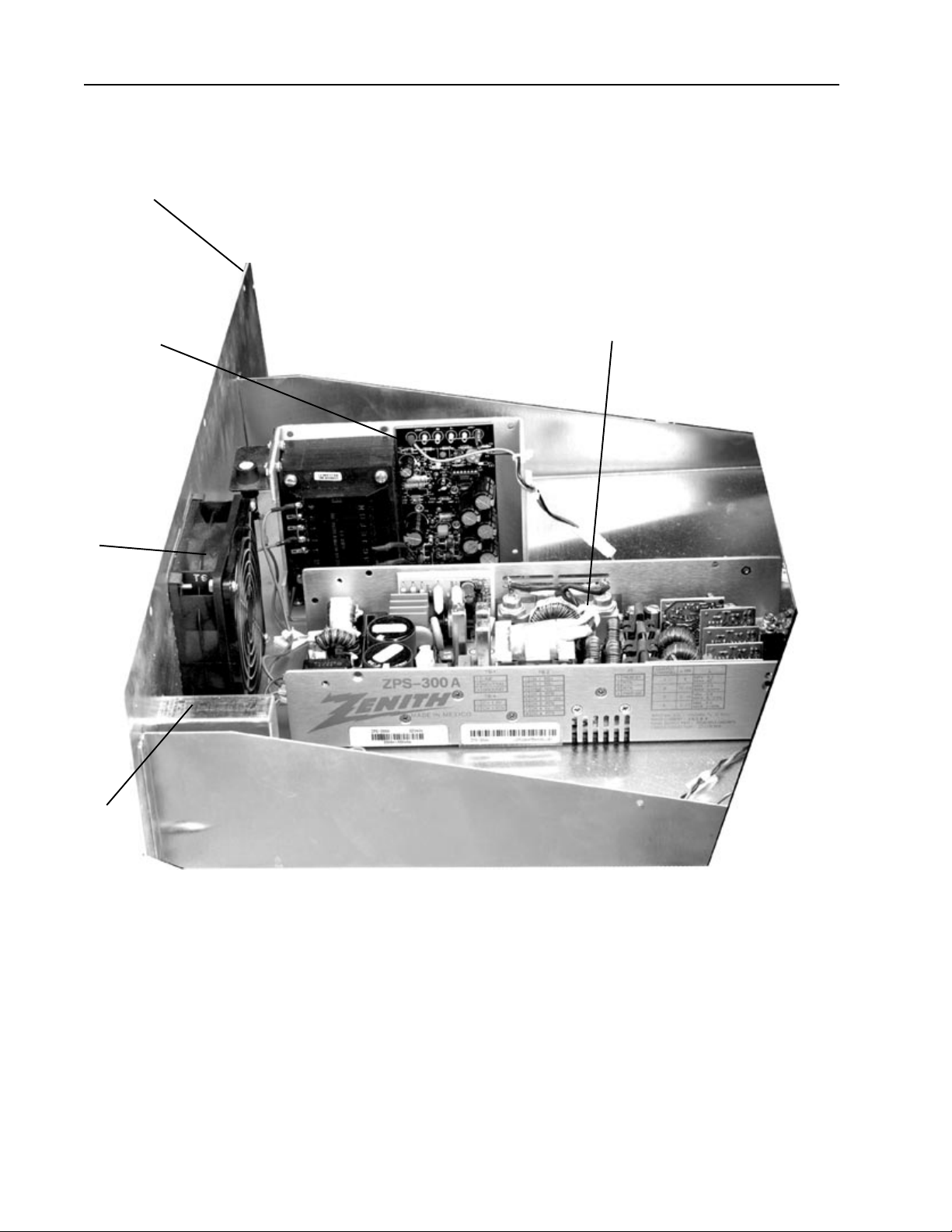
TP8250
PantherPro Image Recorder
1
45
2
3
9-16 November1994
PrePRESS SOLUTIONS CONFIDENTIAL
Page 87

PantherPro Image Recorder TP8250
Group 5 Power Supply Drawer
Key Part Number Description Qty.
1 200 007837 000 Drawer 1
2 3033790 Fan 1
3 505 007599 000 Power Switch 1
3A 4333600 Fuse, 4A (110V) 1
3B 3036770 Fuse, 2.5A (220V) 1
4 505 008917 000 24V Supply (110V) 1
4A 505 008917 001 24V Supply (220V) 1
5 516 007834 000 Zenith Supply 1
6 540 008723 000 Power Drawer Harness 1
PrePRESS SOLUTIONS CONFIDENTIAL
9-17November1994
Page 88
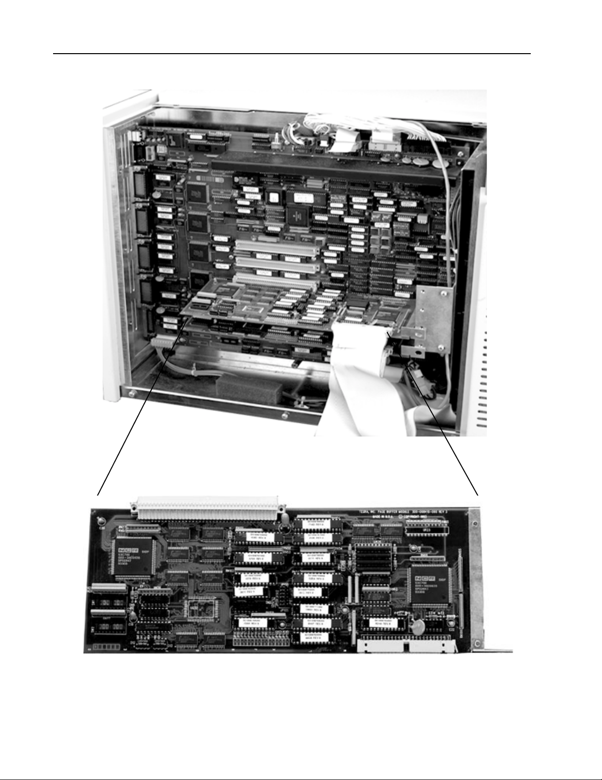
TP8250
PantherPro Image Recorder
HSCB
PBM
9-18 November1994
PrePRESS SOLUTIONS CONFIDENTIAL
Page 89

PantherPro Image Recorder TP8250
Group 6 Card Cage (PCB'S)
Key Part Number Description Qty.
1 505 008414 000 HSCB 1
2 500 008415 001 PBM W/Compression 1
3 540 008940 000 Cable, PBM to Disk Drive 1
3A 540 008940 001 Cable, PBM to Disk Drive 2
PrePRESS SOLUTIONS CONFIDENTIAL
9-19November1994
Page 90
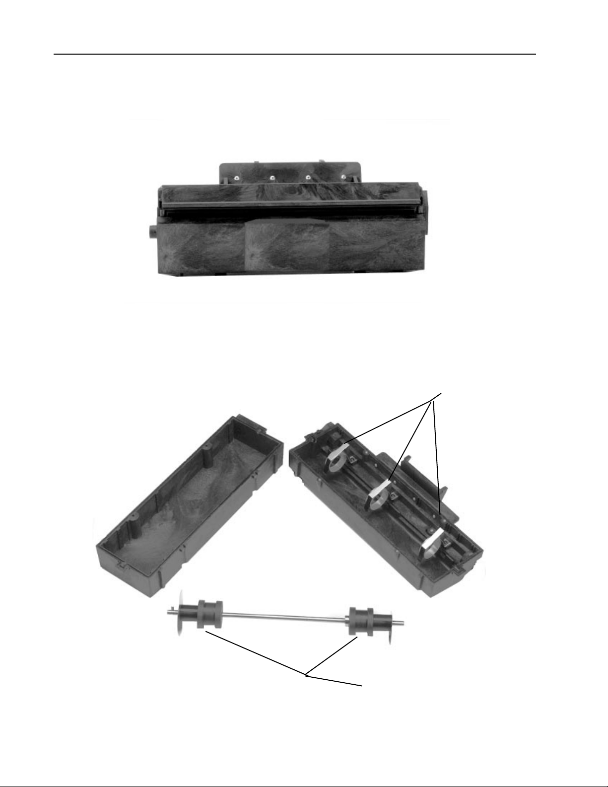
TP8250
PantherPro Image Recorder
Group 7 Take Up Cassette -New Style (Square Plastic)
4
5
9-20 November1994
PrePRESS SOLUTIONS CONFIDENTIAL
Page 91

PantherPro Image Recorder TP8250
Group 7 Take Up Cassette -New Style (Square Plastic)
Key Part Number Description Qty.
1 505 008280 000 High Cap. Take-up Cassette 8" A/R
1A 505 008280 001 High Cap. Take-up Cassette 11" A/R
1B 505 008280 002 High Cap. Take-up Cassette 12" A/R
1C 505 008280 003 High Cap. Take-up Cassette 13.3" A/R
2 505 008551 000 High Cap., 7 mil Take-up Cassette 8" A/R
2A 505 008551 001 High Cap., 7 mil Take-up Cassette 11" A/R
2B 505 008551 002 High Cap., 7 mil Take-up Cassette 12" A/R
2C 505 008551 003 High Cap., 7 mil Take-up Cassette 13.3" A/R
3 706 008281 000 Standard Capacity Take-up Cassette A/R
4 505 008274 000 Tape and Spring Assy. A/R
5 1936300 Disk and Arbor A/R
PrePRESS SOLUTIONS CONFIDENTIAL
9-21November1994
Page 92
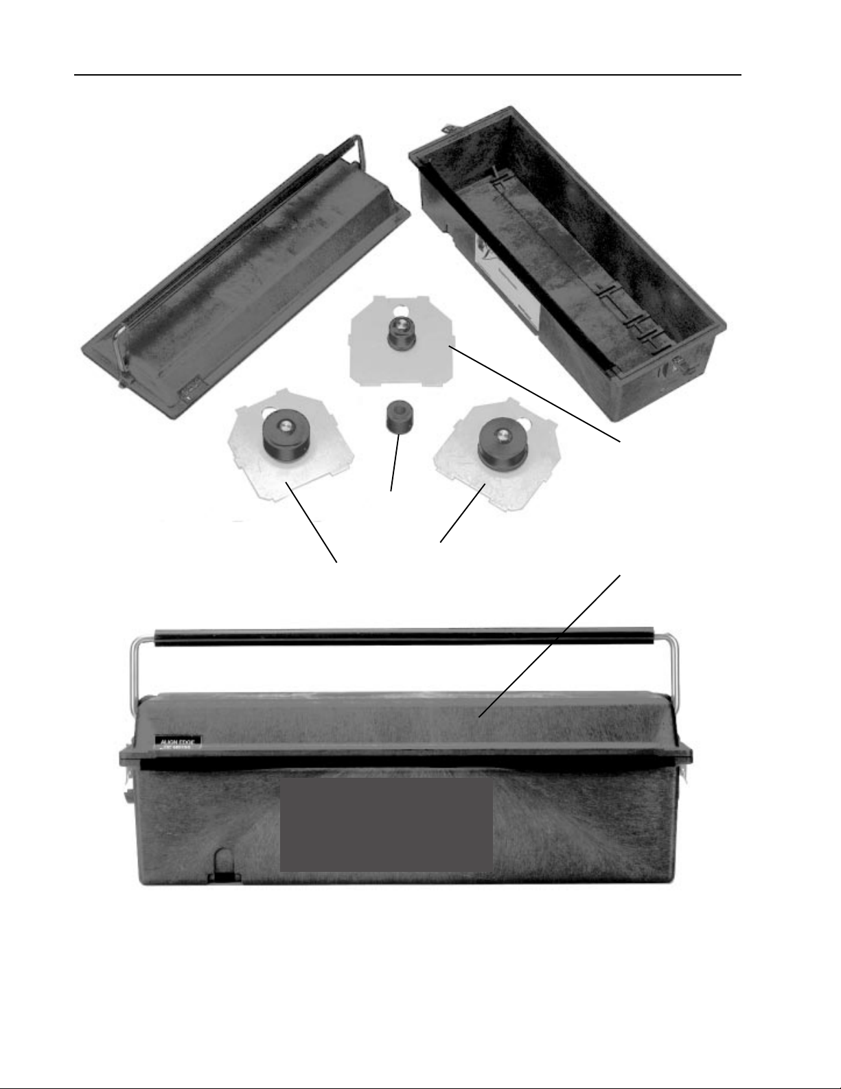
TP8250
PantherPro Image Recorder
6
5
3
2
1
9-22 November1994
PrePRESS SOLUTIONS CONFIDENTIAL
Page 93
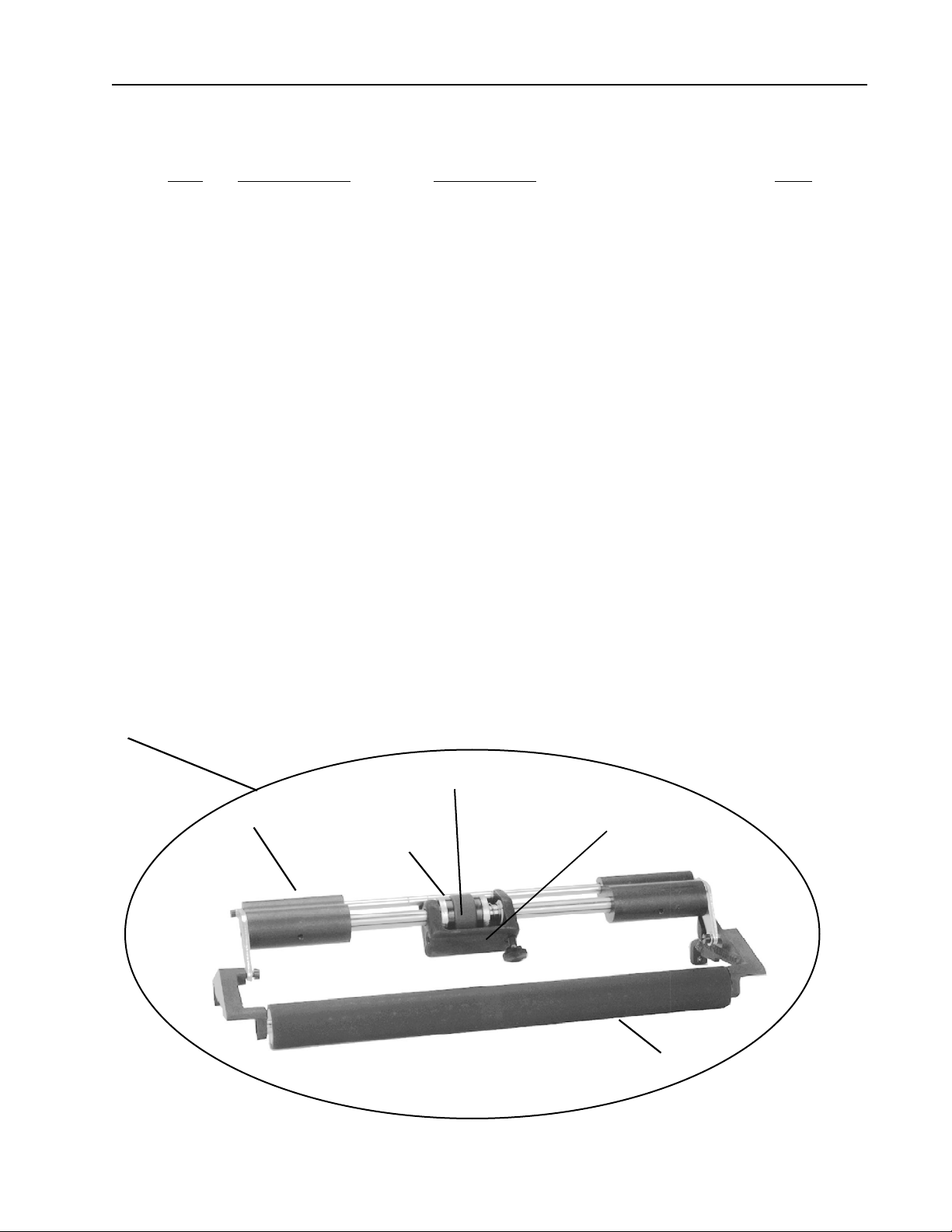
PantherPro Image Recorder TP8250
Group 8 Supply Cassette -New Style (Square Plastic)
Key Part Number Description Qty.
1 505 008573 000 Standard Supply Cassette A/R
2 735 008825 000 246' Supply Cassette A/R
3 735 008825 000 246' Supply Cassette w/ETM A/R
4 200 008883 00 Pre-Cassetted Media Adapter A/R
5 735 008825 001 Pre-Cassetted w/ETM A/R
6 505 008570 000 Film Hub Assy, right side A/R
7 505 008956 000 Paper Hub Assy right side A/R
8 505 008880 000 Film Hub Assy, left side A/R
9 505 008810 000 Paper Hub Assy, left side A/R
10 706 008682 000 Smart Cassette A/R
10A 100 008586 000 1K Bit Memory A/R
1 735 008568 000 External Tensioner Module Kit A/R
2 505 009099 000 ETM Brake Assy A/R
3 735 009100 000 ETM Brake Assy w/Ballast A/R
4 227 008991 000 Ballast A/R
5 206 005295 000 Sleeve Roller A/R
6 202 008508 000 Shaft Roller A/R
7 225 008537 000 Brake Pads A/R
1
5
4 2
7
PrePRESS SOLUTIONS CONFIDENTIAL
6
9-23November1994
 Loading...