

Page 1

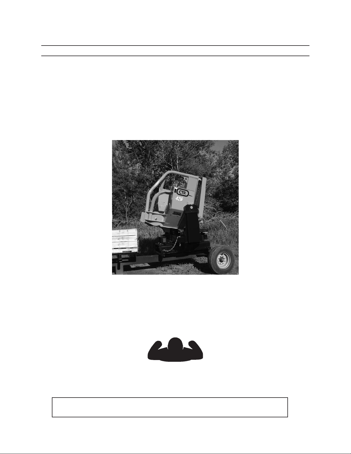
OPERATOR’S MANUAL
Delimber
426
Part No. 30011615
March 2012
Rev. C
Page 2

Page 3

TO THE OPERATOR
CTR426
i
1008
Page 4

TO THE OPERATOR
CTR426
ii
1008
Page 5
TO THE OPERATOR
TO THE OPERATOR
INTRODUCTION
DO NOT OPERATE THIS DELIMBER WITHOUT FIRST READING AND UNDERSTANDING
THIS MANUAL. OPERATORS MUST HAVE THE NECESSARY TRAINING AND AUTHORIZA
TION TO OPERATE AND MAINTAIN THIS DELIMBER PROPERLY.
REMEMBER THAT THE OPERATOR IS THE KEY TO SAFETY. GOOD SAFETY PRACTICES
PROTECT THE OPERATOR AND THE PEOPLE AROUND THE OPERATOR. MAKE THIS
MANUAL A WORKING PART OF THE SAFETY PROGRAM.
CTR426
To safely operate this machine, follow the instructions in this operator’s manual. Directions in this manual are
referenced from the operator’s seat facing forward (see diagram below).
FORWARD
LEFT RIGHT
BACK
You can help improve this manual. If you nd any mistakes, or if you know of a way to improve procedures,
please let us know. Mail your suggestions or comments to the attention of Technical Publications, Caterpillar
Forest Products, Inc., 3249 South County Road 45, PO Box 568, Owatonna, MN 55060-0568.
This operator’s manual includes information available and current at the time of approval for printing
.
Caterpillar Forest Products, Inc., reserves the right to improve its product without giving prior notice or
incurring obligation.
This operator’s manual should be regarded as part of the machine. Suppliers of both new and second hand
machines are advised to retain documentay evidence that this manual was provided with the machine.
CTR426
iii
1008
Page 6
TO THE OPERATOR
WARNING
DANGER
CAUTION
NOTICE
SAFETY SYMBOLS
SAFETY ALERT SYMBOL
THE SAFETY ALERT SYMBOL MEANS
ATTENTION!
BE ALERT!
YOUR SAFETY IS INVOLVED!
This safety symbol is used for important safety messages. To avoid
personal injury and/or property damage, when you see this symbol,
follow the corresponding safety message.
Understand signal words: DANGER, WARNING, and
CAUTION are used with the SAFETY ALERT SYMBOL.
DANGER IDENTIFIES A HAZARD OR UNSAFE
PRACTICE THAT WILL RESULT IN SEVERE PERSON
AL INJURY OR DEATH.
WARNING identies a hazard or unsafe practice
that could result in severe personal injury or death.
CAUTION identies a hazard or unsafe practice that
could result in personal injury or property damage.
CTR426
NOTICE identies important installation, operation, or
maintenance information.
iv
1008
Page 7

TO THE OPERATOR
CONTENTS
PRODUCT PROTECTION PLAN .............................................i
TO THE OPERATOR ..................................................................iii
Safety Symbols .................................................................iv
01 GENERAL SAFETY ........................................................11
Safety Alert Symbol .....................................................1-1
Operator Preparation ..................................................1-1
Danger Area ....................................................................1-2
Delimber Blade Safety ................................................1-2
Discharge Accumulator ..............................................1-3
Electric Lines ...................................................................1-4
Electric Storm .................................................................1-4
Fire Prevention/First Aid .............................................1-5
Fluids Under Pressure..................................................1-5
Handholds & Steps .......................................................1-6
Hand Signals ...................................................................1-6
Hoses & Fittings .............................................................1-7
No Climbing ....................................................................1-7
Operator Safety .............................................................1-7
Pinch Points ....................................................................1-8
Practice Safe Maintanance ........................................1-8
Pressure Settings ..........................................................1-8
Protctive Clothing.........................................................1-9
Protective Devices/Equipment ................................1-9
Saw Bar Safety ................................................................1-9
Saw Operation Safety ............................................... 1-10
Servicing Control Valves, Cylinders,
Pumps & Motors ................................................1-10
Support Components ..............................................1-10
Unauthorized Welding ............................................. 1-10
02 SAFETY DECALS ...........................................................21
Delimber Decals ............................................................2-1
Inside Cab Decals ..........................................................2-2
03 PRESTART INSPECTION ............................................31
04 OPERATION, CONT.
Gooseneck Trailer .........................................................4-6
Connections to Delimber Head ...............................4-6
Tagalong Trailer .............................................................4-7
Topping Saw Oiler ........................................................4-8
Bleeding Topping Saw Oiler ......................................4-8
Bar Oil Flow Adjustment ......................................... 4-10
Bar Oil Flow Adjustment Troubleshooting ....... 4-10
Charging the Accumulator ..................................... 4-11
Joystick Button Functions .......................................4-12
LH Joystick Rocker Switch ...................................... 4-12
RH Joystick Rocker Switch ...................................... 4-12
Removing Trapped Limbs from Knives .............. 4-13
Hydraulic System Adjustments .............................4-14
Preparing to Make Adjustments .......................... 4-14
Beginning Adjustments .......................................... 4-15
Adjustin Knife Arm Blade Open Pressure .......... 4-15
Adjusting Knife Arm Blade Close Pressure ....... 4-16
Adjusting Knife ARm Blade Open Speed .......... 4-16
Adjusting Swa Bar Up Pressure ............................. 4-17
Completing the Process ..........................................4-17
Adjustin Saw Bar Down Pressure ......................... 4-18
Completing the Process ..........................................4-19
Adjusting Saw Bar Up Speed ................................. 4-20
Completing the Process ..........................................4-20
Auto Tensioner Pressure Adjustment ................. 4-21
Completing the Process ..........................................4-21
Detaching the Delimber ......................................... 4-22
Discharging the Accumulator ............................... 4-23
Delimber Blade Safety ............................................. 4-23
05 LUBRICANTS ...................................................................51
Hydraulic Oil ...................................................................5-1
Topping Saw Oil ............................................................5-1
Grease ...........................................................................5-1
Storing Lubricants ........................................................5-2
04 OPERATION.....................................................................41
General Guidelines .......................................................4-1
Operator Preparation ..................................................4-1
General Description .....................................................4-2
Rotation Bearing & Mounting Base ........................4-2
Set Up ...........................................................................4-3
Mounting & Positioning Delimber Units ..............4-3
Cradle Mount Set Up ...................................................4-3
Positioning Delimber on a Gooseneck Trailer ....4-3
Adjusting Rollers ...........................................................4-4
Typical Landing Set Ups .............................................4-5
Hydraulic Connections ...............................................4-6
CTR426
06 MAINTENANCE SAFETY .............................................61
Practice Safe Maintenance ........................................6-1
Delimber Blade Safety ................................................6-2
Discharge Accumulator ..............................................6-2
Fluids Under Pressure..................................................6-3
Hoses & Fittings .............................................................6-3
During Maintenance ....................................................6-4
Hot Hydraulic Oil ...........................................................6-4
Pinch Points ....................................................................6-4
Pressure Settings ..........................................................6-4
Saw Bar Safety ................................................................6-5
v
1008
Page 8

TO THE OPERATOR
NOTES
06 MAINTENANCE SAFETY, CONT.
Saw Operation Safety ..................................................6-5
Servicing Control Valves, Cylinders,
Pumps & Motors ...................................................6-5
Support components ..................................................6-6
Unauthorized Welding ................................................6-6
After Maintenance ........................................................6-7
Storing Flammable Materials ...................................6-7
07 SCHEDULED / PERIODIC
MAINTENANCE SERVICES ..........................................71
Lubricaton Notice .........................................................7-1
Position Machine for Maintenance ........................7-1
Maintenance Chart ......................................................7-2
Hydraulic Pressure ........................................................7-3
Preparing for Saw Bar and Chain Maint. .............7-4\
Maintenance - As Required .......................................7-5
Clean & Grease Cylinder Rods ..................................7-5
Replace Saw Chain .......................................................7-6
Sharpen Saw Chain ......................................................7-8
Machine Grinding Teeth .............................................7-8
Recondition Saw Bar ....................................................7-9
Sharpen Delimber Knife Arm Blades .....................7-9
Replace Delimber Knife Arm Blades ...................7-10
Reassemble Delimber Blade Arms ...................... 7-11
Adjust Bar Oil Flow .................................................... 7-12
Maintenance - Daily or Every 10 Hours .............. 7-13
Performa Daily Visual Inspection ......................... 7-13
Check Oil Level for Topping Saw Oiler ...............7-13
Maintenance - Weekly or Every 50 Hours ......... 7-14
Perform a Weekly Inspection ................................. 7-14
Lubricate Delimber ................................................... 7-15
Lube Knife Arm Tubes .............................................. 7-15
Lube Topping Saw Cylinder ...................................7-15
Lube Knife Arm Cylinder ......................................... 7-15
Lube Saw Bearings .................................................... 7-16
Lube Feed Roller Shafts ........................................... 7-16
Lube Cradle Rollers ................................................... 7-16
Inspect Knife Arm Blades ........................................ 7-17
Lube Large Rotation bearing ................................. 7-17
Lube Saw Bar Bearing .............................................. 7-17
Maintenance - Monthly or Every 250 Hours .... 7-18
Adjust Cradle Rollers ................................................7-18
10 SPECIFICATIONS ........................................................101
Delimber Specs .......................................................... 10-1
Hyd. Connection Torque Specs, 37 Deg. Flare . 10-2
Hyd. Connection Torque Specs, O-Ring ............. 10-3
Torque Chart for Fasteners ..................................... 10-4
Cylinder Torque Specs .............................................. 10-5
11 SERIAL NUMBERS ......................................................111
12 MSDS .............................................................................. 121
13 GLOSSARY ....................................................................131
08 TRANSPORTING ............................................................81
09 STORAGE .........................................................................91
Preparing for Storage ..................................................9-1
Taking Delimber Out of Storage..............................9-2
CTR426
vi
1008
Page 9
DANGER
OPERATOR’S MANUAL.
GENERAL SAFETY
GENERAL SAFETY
DO NOT OPERATE MACHINE WITHOUT READING AND UNDERSTANDING THIS
SAFETY ALERT SYMBOL
Read all safety messages.
To avoid personal injury and/or property damage, follow all safety messages.
OPERATOR PREPARATION
G.100.05
Before operating this machine Operator must:
• read and understand the Operator’s Manual
• be procient in the control of this machine
• understand the safety features of this machine
• be instructed in the local work sate safety rules
CTR426
11
1008
Page 10
WARNING
WARNING
DELIMBER
LOADER
GENERAL SAFETY
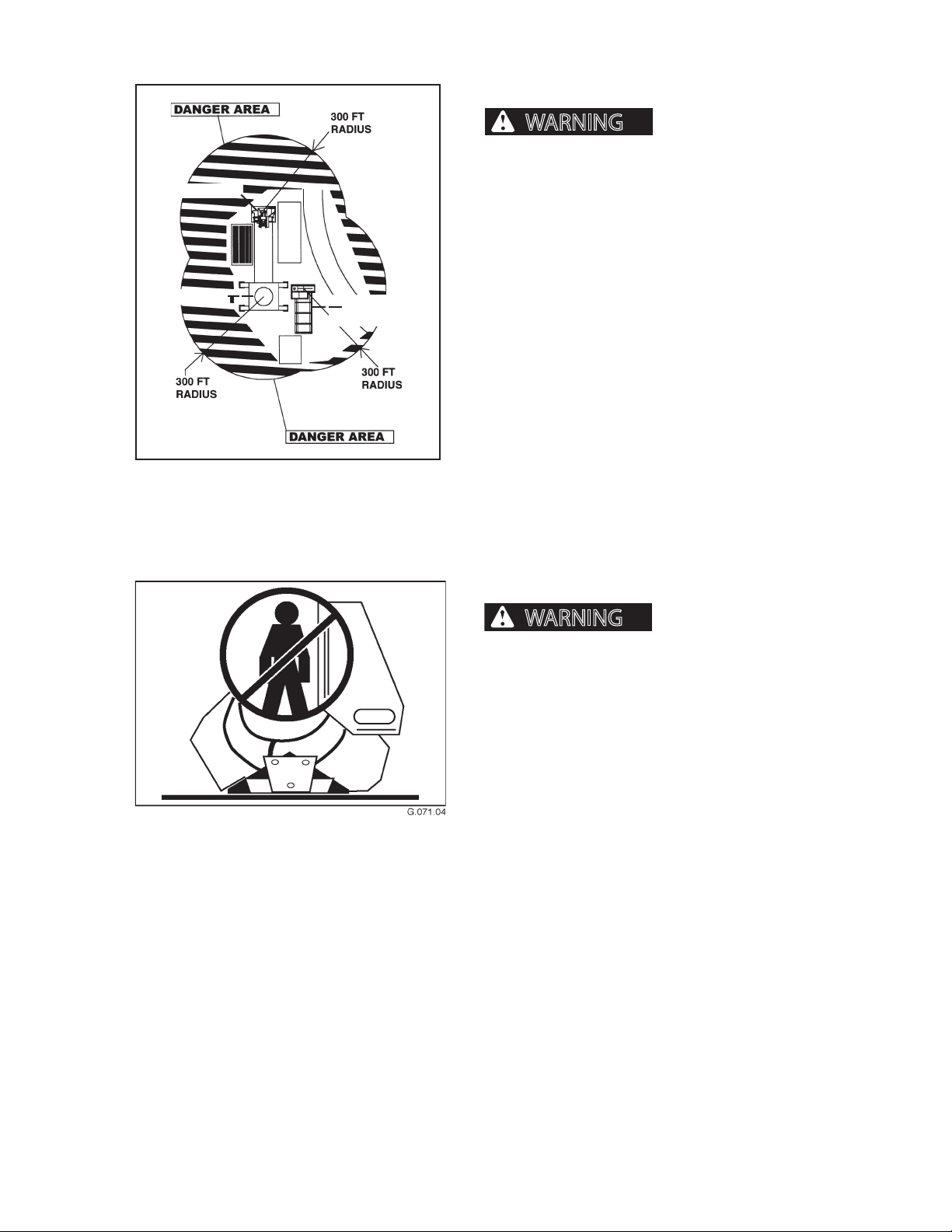
DANGER AREA
Flying debris, falling
trees, limbs and tops can cause severe personal injury or death. Do not operate delimber within 300
feet (91 meters) of personnel or property.
Any area within a 300 foot radius of the delimber,
loader and slasher units is considered a danger area.
Area illustrated serves as a guideline and should be
enlarged when warranted by working conditions.
SLASHER
GROUND SAW
G.070.04
DELIMBER BLADE SAFETY
Charged accumulator can
close delimber blades resulting in severe personal
injury or death. DO NOT enter the delimber area
without closing delimber blades, shutting engine
down, discharging accumulator and blocking out
tilting in delimber base frame.
CTR426
12
1008
Page 11
GENERAL SAFETY
WARNING
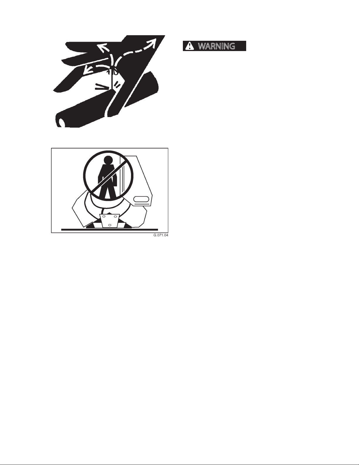
DISCHARGE ACCUMULATOR
the delimbing knife area or working on the hydraulic system can lead to serious personal injury or
death.
Unless certain that the accumulator is discharged, do
not stand or work in the delimbing knife area.
The accumulator is charged with hydraulic pressure
to open and close the delimber blades during normal
operation. The accumulator can close the delimber
blades without the engine driving the hydraulic pump.
Therefore, it is very important that BEFORE entering
the area around the delimber blades or doing any
work on the hydraulic system, the accumulator MUST
be discharged. If the accumulator is not discharged,
the blades may close, causing serious personal injury
or death.
See Section 4, Operation, for instructions on discharging the accumulator.
Standing or working in
CTR426
13
1008
Page 12
GENERAL SAFETY
WARNING
DANGER
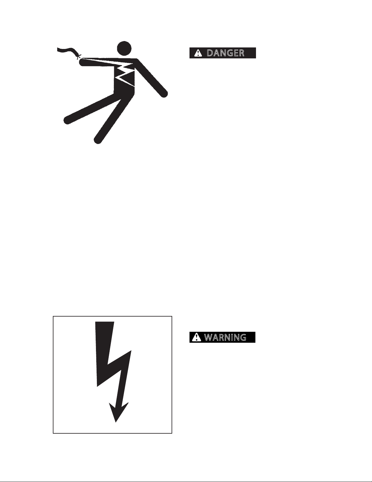
ELECTRIC LINES
DEATH WILL RESULT FROM CONTACT WITH ELEC
TRIC LINES.
Never move any part of machine or load closer than
10 feet plus twice the line insulator length to electric
lines. A line insulator is what connects an electric line
to an electric pole.
For example, if a line insulator is 6 inches long, stay at
least 10 feet plus twice the line insulator length (2x6
=12 inches or 1 foot) from electric line, which means
machine must stay at least 11 feet from this electric
line.
If machine touches an electric line, stay inside the cab.
Carefully move machine or load away from electric
line, without pulling the line down.
DO NOT allow anyone else to touch machine while
it is touching an electric line. If machine cannot be
moved away from the electric line without pulling line
down, have someone contact the utility company to
disconnect power from line. If this is not possible, or
if machine begins to burn, jump away from machine
to the ground with both feet together, in one smooth
jump. DO NOT touch machine and ground at the same
time or else electricity in the line will go through the
body. Get away from machine after jumping.
SERIOUS INJURY OR
Notify utility company immediately. DO NOT let anyone near machine while it is touching an electric line.
ELECTRICAL STORM
Electrical storms (lightning) can cause severe personal injury or death.
When lightning is striking in the vicinity of the
machine, the operator should NEVER attempt the
following procedures:
Mount the machine
Dismount the machine
If you are in the operator’s station during an electrical
storm, stay in the operator’s station. If you are on the
ground during an electrical storm, stay away from the
vicinity of the machine.
CTR426
14
1008
Page 13
GENERAL SAFETY
CAUTION
WARNING
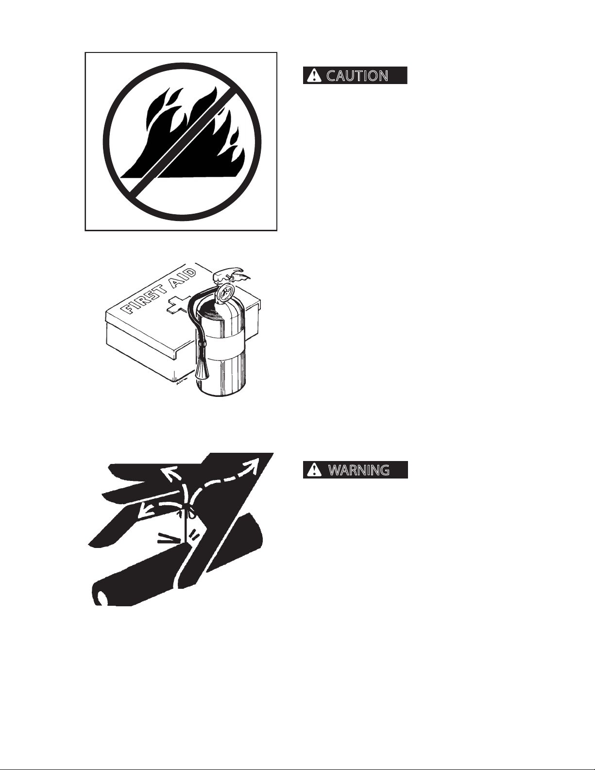
FIRE PREVENTION/FIRST AID
injury and/or machine damage.
Keep machine clean. Forest debris, rags, and trash will
cause res. Remove all debris, rags, and trash from
machine, especially around engine and hydraulic
components.
Repair all hydraulic and fuel leaks immediately. Do not
operate machine with hydraulic or fuel leaks.
Fire prevention beats re ghting. Remove debris from
all compartments after every 8 hours of operation, or
more often, if warranted by working conditions.
At the end of each shift ALWAYS stay with the machine
for 30 minutes after shutting down the engine to
ensure there is no forest debris/trash re start up. Keep
a re extinguisher ready during this 30 minute cool
down.
Install a rst-aid kit in the cab.
Fires can cause personal
Properly maintain rst-aid kit and re extinguisher. Follow instructions provided with them.
FLUIDS UNDER PRESSURE
Fluids escaping under
pressure can penetrate skin and cause severe personal injury or death.
Wear eye and personal protection equipment
(PPE)!
Always use a board or cardboard when checking oil
hoses, lines, and ttings for leaks, cracks, or defects.
Be sure all clamps are in their proper position and
torqued as required and specied. Be sure hoses are
not twisted or touching parts.
CTR426
DO NOT use hands to search for leaks. Escaping uids
can penetrate skin and enter the bloodstream. Before
disconnecting lines, relieve all pressure.
DO NOT apply pressure to a damaged hose, line, or
tting.
If ANY uid is injected beneath the skin, seek medical
attention immediately. A serious infection or reaction
can result without proper medical treatment.
15
1008
Page 14
GENERAL SAFETY
WARNING
WARNING
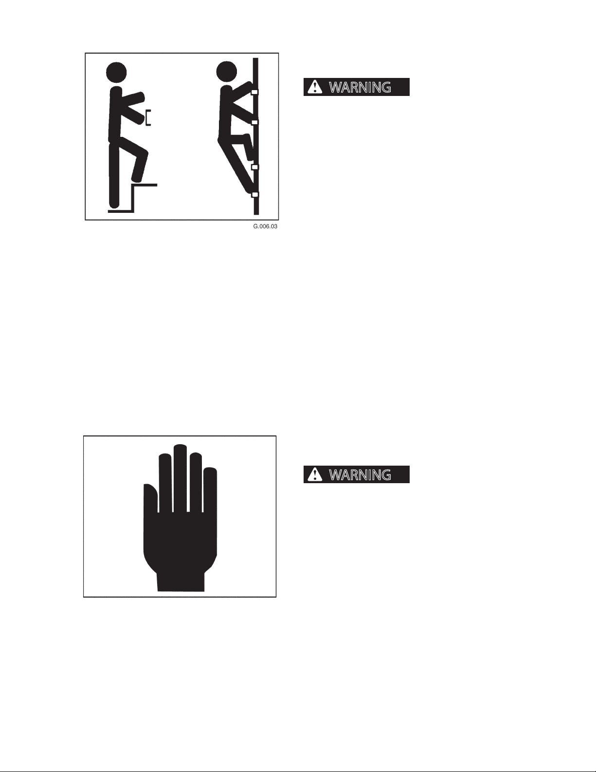
HAND HOLDS AND STEPS
severe personal injury or death.
Use provided hand holds and steps while maintaining at least 3 points of support (1 foot and 2 hands
or 2 feet and 1 hand) when getting on and o machine. Face machine when getting on and o of it.
Never use controls as hand holds. Never use steering wheel as a hand hold. Moving the steering
wheel from its center position will COMPLETELY
turn machine right or left.
DO NOT mount machine if hand rails or steps are
broken or missing. Get them repaired rst.
DO NOT jump on or o machine unless it has
touched a live electrical wire and it must be exited.
Ensure rm foot position when getting on and o
machine. Be careful of slippery conditions on platform, steps, and hand holds when getting on and
o machine.
Slips and falls can cause
Remove oil, grease, mud, ice, etc. before mounting
or dismounting machine.
To prevent slips and falls, replace skid-resistant material if it is worn, damaged or missing.
HAND SIGNALS
Accidents can cause severe personal injury or death.
Know and use hand signals required for particular jobs.
Know who has responsibility for signaling.
CTR426
16
1008
Page 15
GENERAL SAFETY
WARNING
WARNING
WARNING
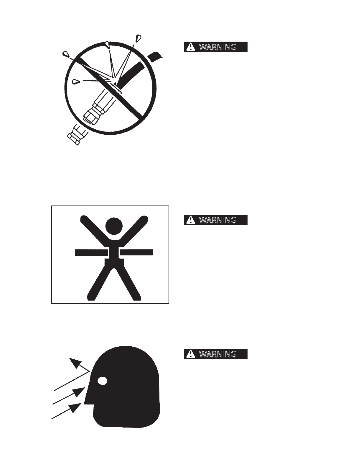
HOSES AND FITTINGS
types of hoses and ttings can blow apart and
cause severe personal injury or death.
DO NOT interchange brands or types of hoses and
ttings.
DO NOT install a tting from one manufacturer on a
hose from a dierent manufacturer.
DO NOT install crimp ttings on hoses meant for reusable ttings.
Wear eye and personal protection equipment
(PPE)!
Always use a board or cardboard when checking oil
hoses, lines, and ttings periodically for leaks, cracks or
defects. Be sure all clamps are in their proper position
and torqued as required and specied. Be sure hoses
are not twisted or touching parts.
Mismatched brands or
NO CLIMBING
Personell can fall from
delimbers or be injured by movement of delimber,
causing severe personal injury or death. Slips and
falls can cause severe personal injury or death.
DO NOT allow personell on any delimber that is operating.
NEVER jump on or o delimber.
ALWAYS use extreme caution when standing on or
near delimber, which can tilt and cause operator to
lose balance.
OPERATOR SAFETY
Flying debris, tree limbs,
and/or other material can cause severe personal
injury or death.
CTR426
When operating delimber:
1. Do not operate delimber within 300 feet (91 meters)
of personnel or property.
2. Wear eye and personal protection equipment (PPE)!
17
1008
Page 16
GENERAL SAFETY
WARNING
WARNING
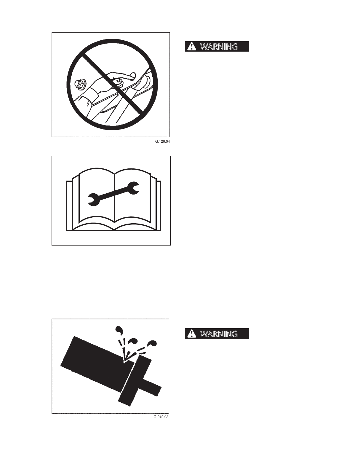
PINCH POINTS
tion of the body where delimber moves can cause
severe personal injury or death. NEVER place hands
or any portion of the body where injury could occur
if delimber moves. NEVER check pin hole alignments with ngers.
PRACTICE SAFE MAINTENANCE
Understand services procedures before performing
maintenance. When performing maintenance, keep
area around machine clean and dry.
Placing hands or any por-
G.104.05
DO NOT service delimber while it is in operation. Keep
away from power-driven parts. Disengage power. Shut
engine down. Move controls in all directions to relieve
hydraulic pressure. Depressurize delimber accumulator. Remove key from ignition. Allow machine to cool
down.
Support all raised equipment.
Keep all delimber parts in good condition, and be sure
parts are properly installed. Repair damage immediately. Repair all hydraulic and fuel leaks immediately.
Replace worn or broken parts. Remove any buildup of
grease, oil or debris.
Disconnect battery ground cable (-) before adjusting
electrical system.
PRESSURE SETTINGS
Excessive hydraulic pressure can cause component or structural failure,
which may result in severe personal injury or
death. Wear eye and personal protection equipment (PPE)!
CTR426
DO NOT exceed factory-adjusted pressure settings.
18
1008
Page 17
GENERAL SAFETY
WARNING
WARNING
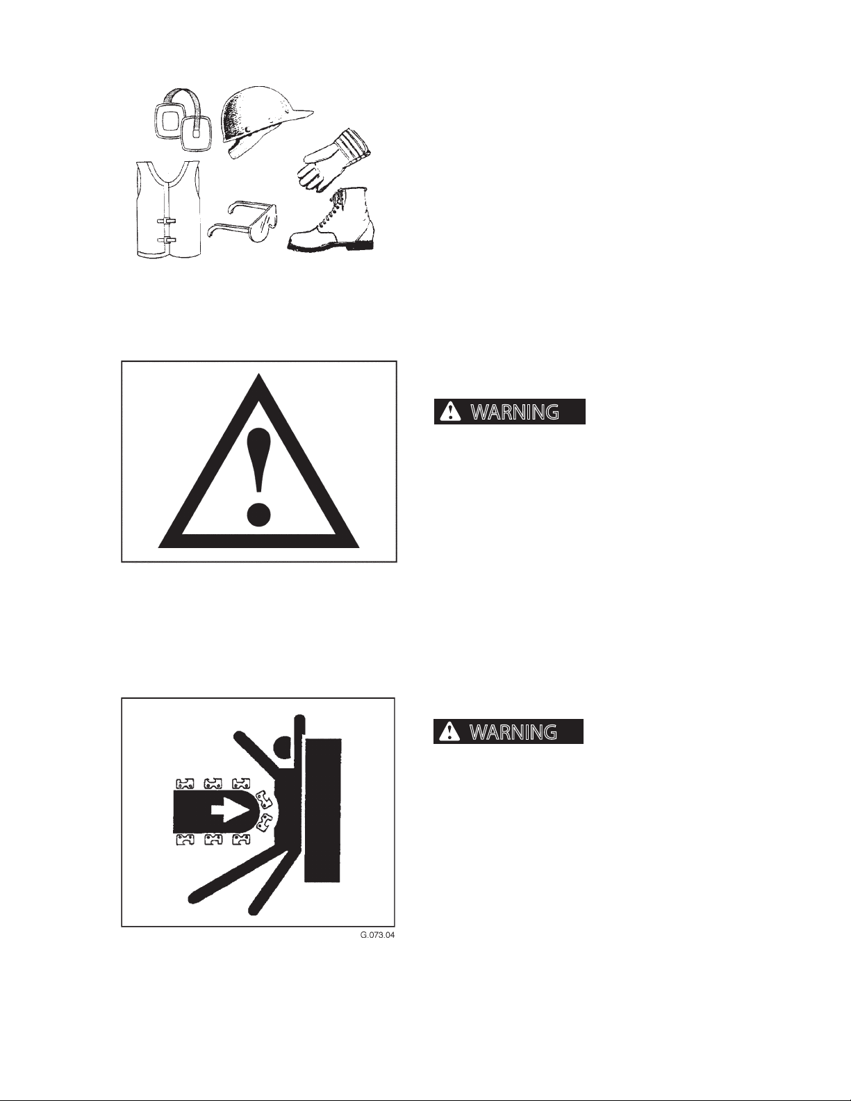
PROTECTIVE CLOTHING
Wear OSHA-approved protective clothing when working on or near this machine, such as
• ear protection • hard hat
• gloves • orange vest
• goggles • steel-toed shoes
Wear snug, protective clothing that is belted where
required.
Remove jewelry before working on or near this machine.
PROTECTIVE DEVICES/EQUIPMENT
ignorance of protective equipment or devices can
cause severe personal injury or death.
Misuse, interference and
Alarms, re prevention equipment, ROPS/FOPS/OPS,
and other safety equipment is installed on machine for
the operator’s protection.
Never ignore, disconnect, disable or modify protection
equipment in any manner.
SAW BAR SAFETY
Loss of hydraulic pressure
in the loader or delimber can cause the saw bar to
fall. A falling saw bar can cause severe personal
injury or death.
NEVER handle the saw bar when loader is running.
ALWAYS wear personal protection equipment (PPE),
especially gloves, when handling the saw bar.
CTR426
19
1008
Page 18
GENERAL SAFETY
WARNING
NOTICE
WARNING
WARNING
WARNING
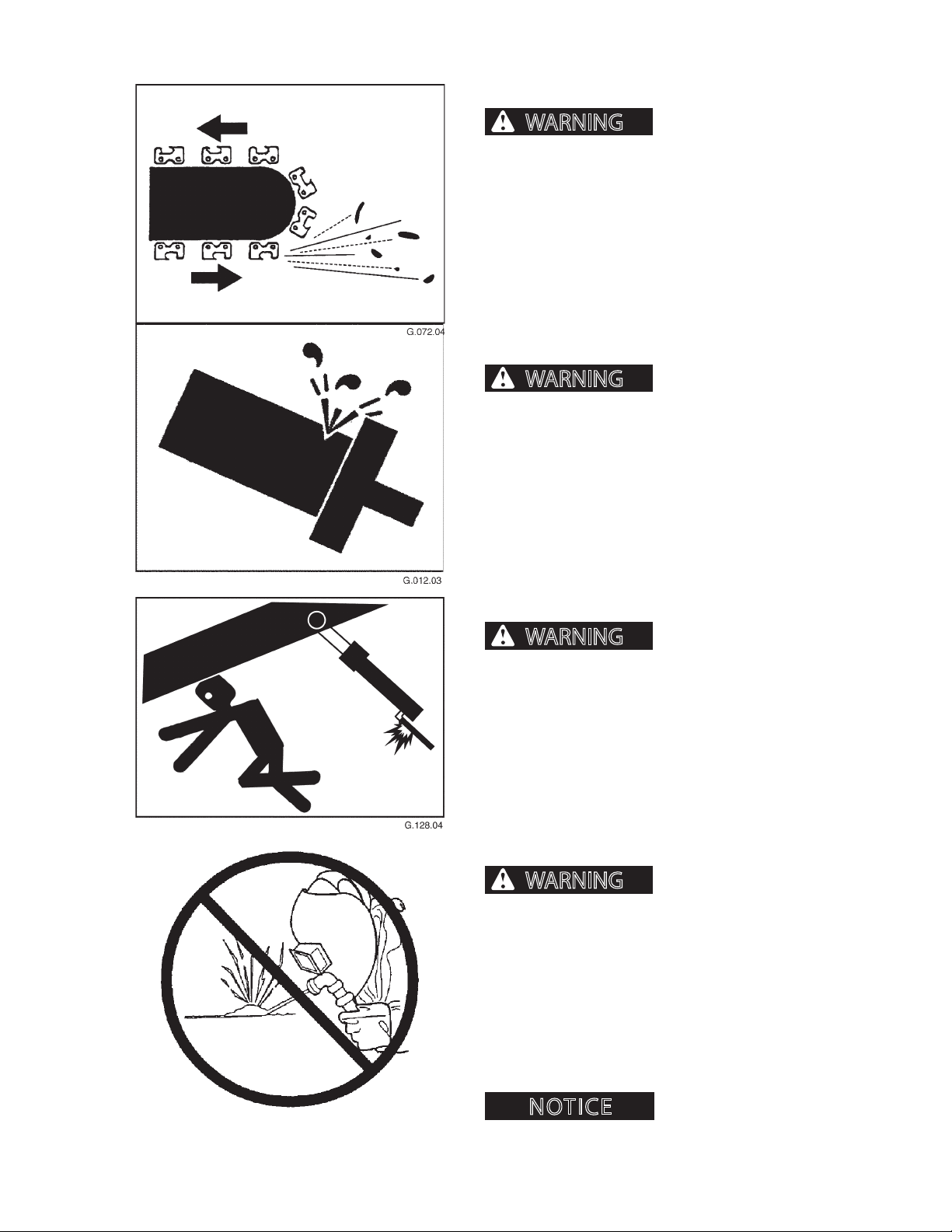
SAW OPERATION SAFETY
bris can cause severe injury or death. Keep loader
door closed when operating saw.
To prevent damage from ying debris, align saw bar
away from loader and other equipment.
Do not operate delimber within 300 feet (91 meters) of
personnel or property.
SERVICING CONTROL VALVES, CYLINDERS, PUMPS
AND MOTORS
settings could cause delimber or component failure
resulting in severe personal injury or death. Do not
change pressure settings. Do not switch lines from
one valve to another.
Special tools and training are required to service control valves, cylinders, pumps and motors. If these parts
need services, see an authorized dealer.
Flying particles and de-
Increasing relief valve
SUPPORT COMPONENTS
When working beneath
delimber or delimber parts, if a hose breaks or a
control is moved, machine parts such as boom or
attachment may fall resulting in serious injury or
death. Provide support for components. DO NOT
depend on hydraulic cylinders for support.
UNAUTHORIZED WELDING
Unauthorized welding
can cause structural failure and/or severe personal
injury or death.
DO NOT weld on any structural member.
Any unauthorized welding or repair will void
the Warranty.
Once authorized, turn battery disconnect switch OFF
and place welding ground (stinger) as close to the
weld site as possible. Do not allow weld current to pass
through bearings or pivot points.
CTR426
to the electrical system.
110
Welding can cause damage
1008
Page 19
SAFETY DECALS
NOTICE
DANGER
10065084 1/05
STAY CLEAR
IF DELIMBER IS ACTIVATED
WITH PERSON IN AREA,
SEVERE INJURY OR DEATH
COULD OCCUR.
NEVER STAND IN AREA
WHEN MACHINERY IS IN
OPERATION.
DANGER
10065083 1/05
IF SAW IS OPERATING WITH
PERSON IN IMMEDIATE AREA,
SEVERE INJURY OR DEATH
COULD OCCUR.
NEVER STAND IN THIS AREA
WITH LOADER ENGINE
RUNNING.
DANGER
10065084 1/05
STAY CLEAR
IF DELIMBER IS ACTIVATED
WITH PERSON IN AREA,
SEVERE INJURY OR DEATH
COULD OCCUR.
NEVER STAND IN AREA
WHEN MACHINERY IS IN
OPERATION.
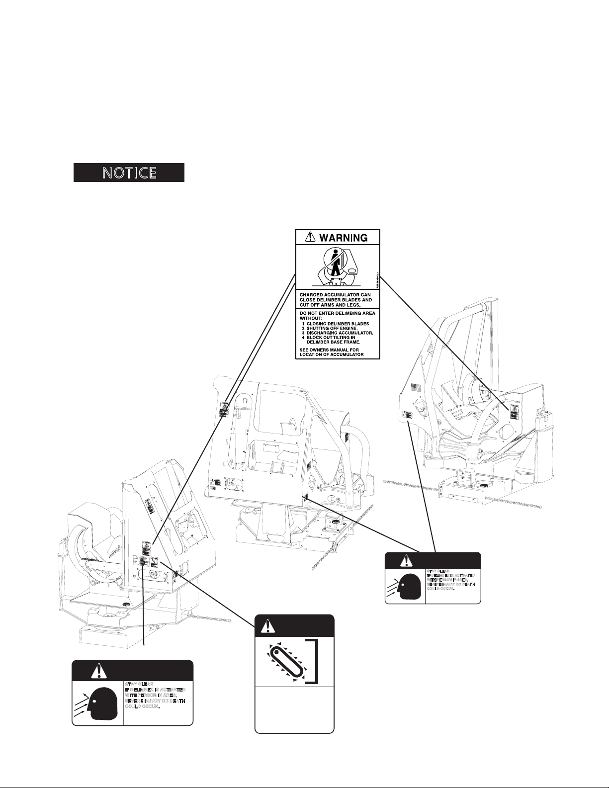
SAFETY DECALS
The following safety decals are located in positions on the machine as continual reminders of HAZARDS. Serious
injury or property damage can occur if safety instructions are not followed.
Keep all safety decals clean and readable. Use a soft cloth, water and soap to clean decals if they are too dirty to
read. DO NOT clean safety decals with solvent. Solvent can damage them.
Replace safety decals immediately if they are damaged, missing or hard to read. Contact a CTR dealer for replacement safety decals. A CTR dealer will provide free replacement safety decals when provided a valid CTR machine
serial number.
.
If replacing a part that has a safety decal, apply a new safety decal to the replacement part. Before putting a new decal on the machine or part, be sure the surface where decal wil lbe mounted
is clean and dry.
CTR426
21
1008
Page 20
SAFETY DECALS
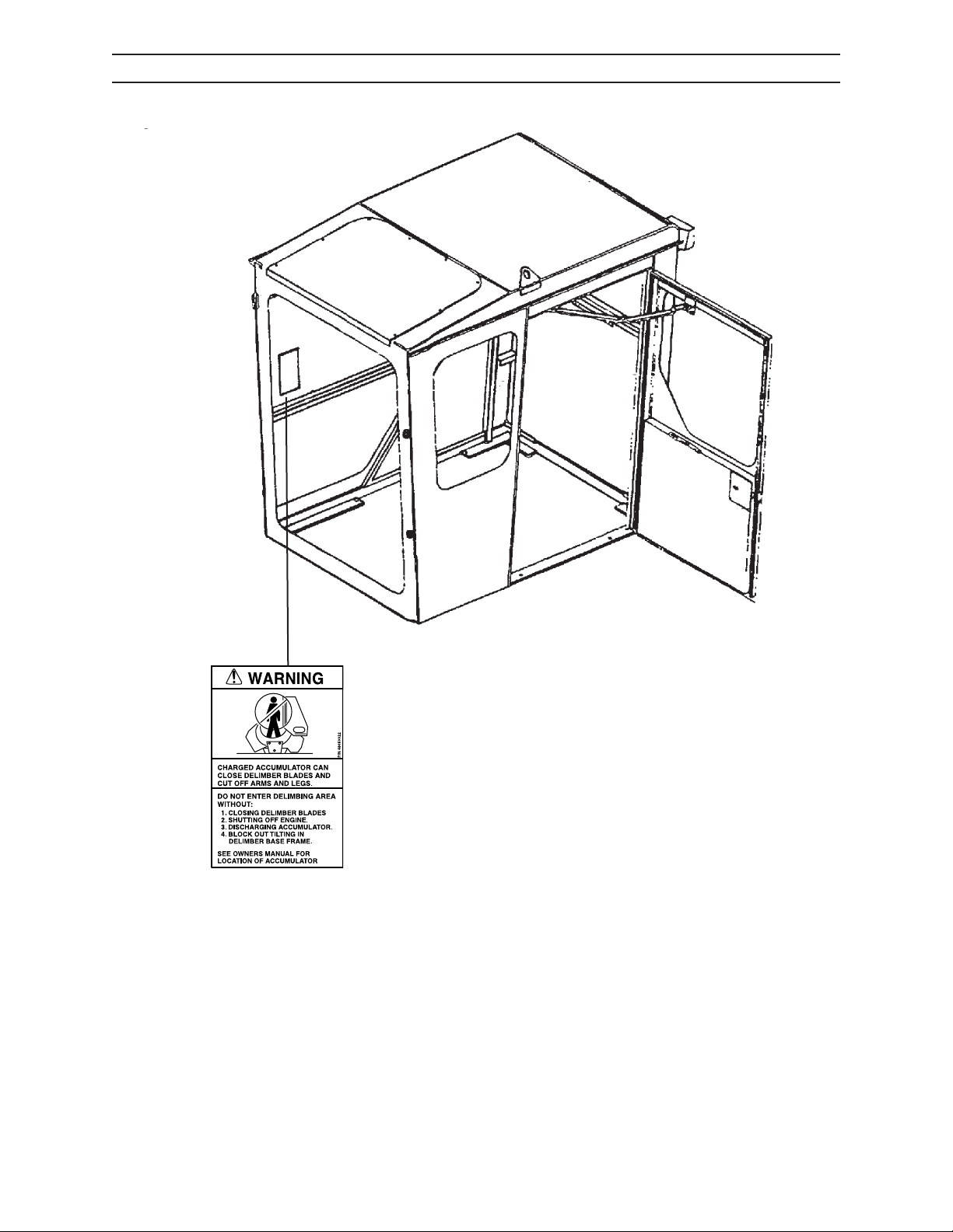
INSIDE CAB
CTR426
22
G.069.04
1008
Page 21
PRESTART INSPECTION
WARNING
WARNING
NOTICE
This machine may not be used until operators have read, studied, and understand this manual, and have learned how to properly operate this machine. Operating this machine without reading, studying, and understanding this manual could result in severe personal injury or death.
Failure to perform a daily inspection of the machine could result in machine
damage and severe personal injury.
Inspector’s Initials
Check for protective clothing (wear it) and safety equipment (know where it is).
Check entire machine by performing a thorough walk-around inspection.
Check for loose or missing parts. Tighten loose parts; replace missing parts.
Check for leaks in hydraulic hoses and/or lines (replace defective hoses and/or lines).
Check hydraulic hoses and lines for wear and/or damage. Replace any defective hoses and/or lines.
Check that machine has been properly lubricated as described in Scheduled and Periodic Maintenance
Services section.
Check shields and guards. They must be in place and undamaged. Replace damaged shields and guards.
Check for ice, snow, oil, and grease on steps and handrails. Clear away ice, snow, mud, oil, and grease to
prevent slips and falls.
Check for any damaged or worn steps and handrails. Replace if damaged or worn.
Check that safety decals are on machine and that they are readable.
Check that shut-o valves are open (if equipped).
Check for dirt and grime on all hydraulic components. Remove dirt and grime to help prevent overheating.
Check hydraulic oil reservoir level. Add hydraulic oil to reservoir if necessary.
Check for combustible or ammable materials. Remove them from delimber, if found.
Check mounting hardware. Tighten, if necessary.
Check that machine will not be near electrical wires. See Operation section for more details.
Check bar chain oil reservoir. Add bar chain oil if necessary.
Check bar chain for damage or wear. Replace if damaged or worn.
Machine Serial NumberDate of Inspection
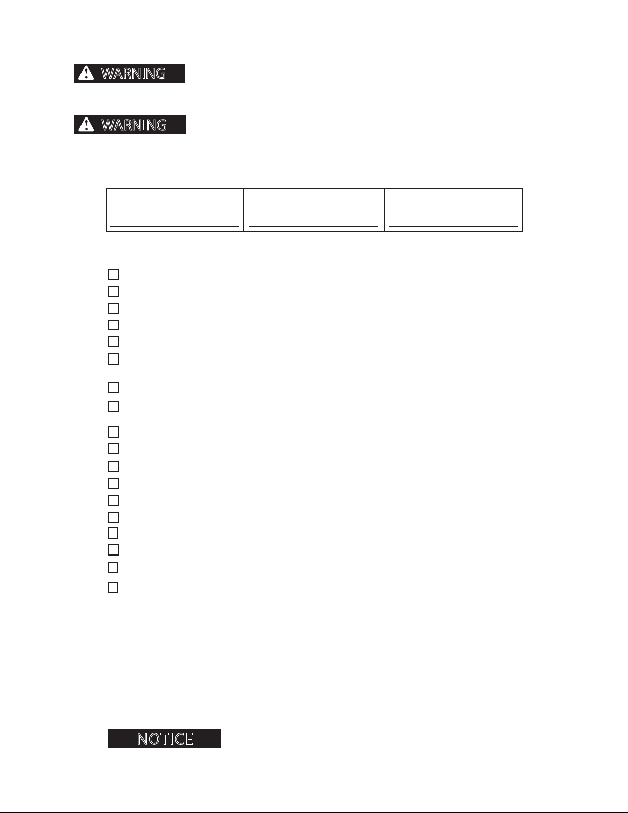
Pages in this section may be copied. Check o each inspection
item before operating machine. File the copy as a record of
inspection as required by OSHA or local governing body.
31
1008CTR426
Page 22

NOTES
CTR426
32
1008
Page 23
OPERATION
WARNING
OPERATION
GENERAL GUIDELINES
Only a trained, qualied and authorized operator shall be allowed to operate
this delimber. Only use this delimber after carefully reading this manual and learning how to safely operate and maintain this delimber. Unsafe operation can result in serious personal injury or death.
OPERATION PREPARATION
Operator must be fully trained, qualied and authorized to operate this delimber.
Before running this delimber, operator must know the
location and purpose of
• controls
• instruments
• local operating safety rules and procedures
• safety and instruction decals (see Safety Decals
G.100.05
section)
Operator must be at least 18 years old to operate this delimber (Code of Federal Regulations: Labor).
Never operate this delimber while under the inuence of drugs or alcohol. Use of prescription or over-the-counter drugs or medications requires advice from a medical practitioner on whether or not delimber can be safely
operated.
Do not operate this delimber if subject to dizziness, seizures or motion disturbance.
No personell is allowed on this delimber. Delimber personell can fall from machine or be injured by movement of
machinery, causing severe personal injury or death. Do not allow personell on a delimber that is operating.
Follow all safety operating instructions and practices. (See General Safety section.)
Keep delimber away from power lines.
If this manual is lost, contact an authorized dealer for a new manual. Keep manual with delimber.
Report any noticeable delimber problems to people who can repair the problems before delimber is used.
Do not operate delimber within 300 feet (91 meters) of personnel or property.
REMEMBER THAT THE OPERATOR IS KEY TO THE SAFE OPERATION OF THIS DELIMBER.
CTR426
41
1008
Page 24
OPERATION
GENERAL DESCRIPTION
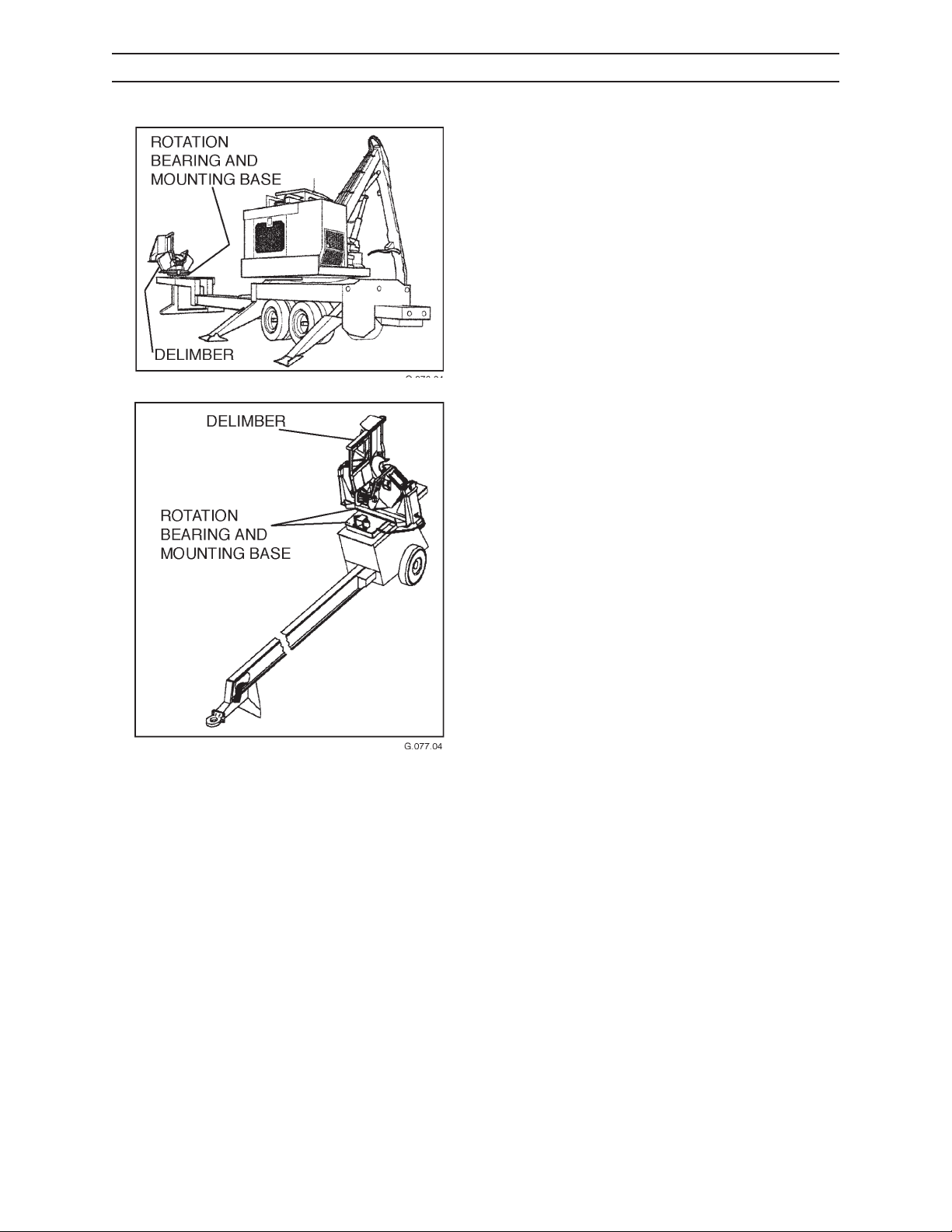
The delimber can be mounted on a gooseneck trailer
with a loader or on a tagalong trailer.
This is a pull-through type delimber with a topping
saw that is operated by loader controls. Its function is
delimbing hardwoods or softwoods.
Power is supplied to the delimber through the loader
hydraulic system.
The loader operator places a tree into the delimber.
The operator then closes the delimber blades and
pulls the felled tree through the delimber, pressing the
stem gently against the roller. Once the tree has been
delimbed, the operator may use the topping saw to
top the tree or cut the stem to the desired length.
ROTATION BEARING AND MOUNTING BASE
The large rotation bearing in the mounting base
permits the delimber to align with the tree stem as it is
pulled through the delimber.
CTR426
42
1008
Page 25
OPERATION
WARNING
SET UP
MOUNTING AND POSITIONING
DELIMBER UNITS
Contact with the delimber
while lifting or tranporting can cause equipment
damage, severe personal injury or death.
Welding of the delimber sub-base to the mounting
platform is normally done at the factory or authorized
dealership.
CRADLE MOUNT SET UP
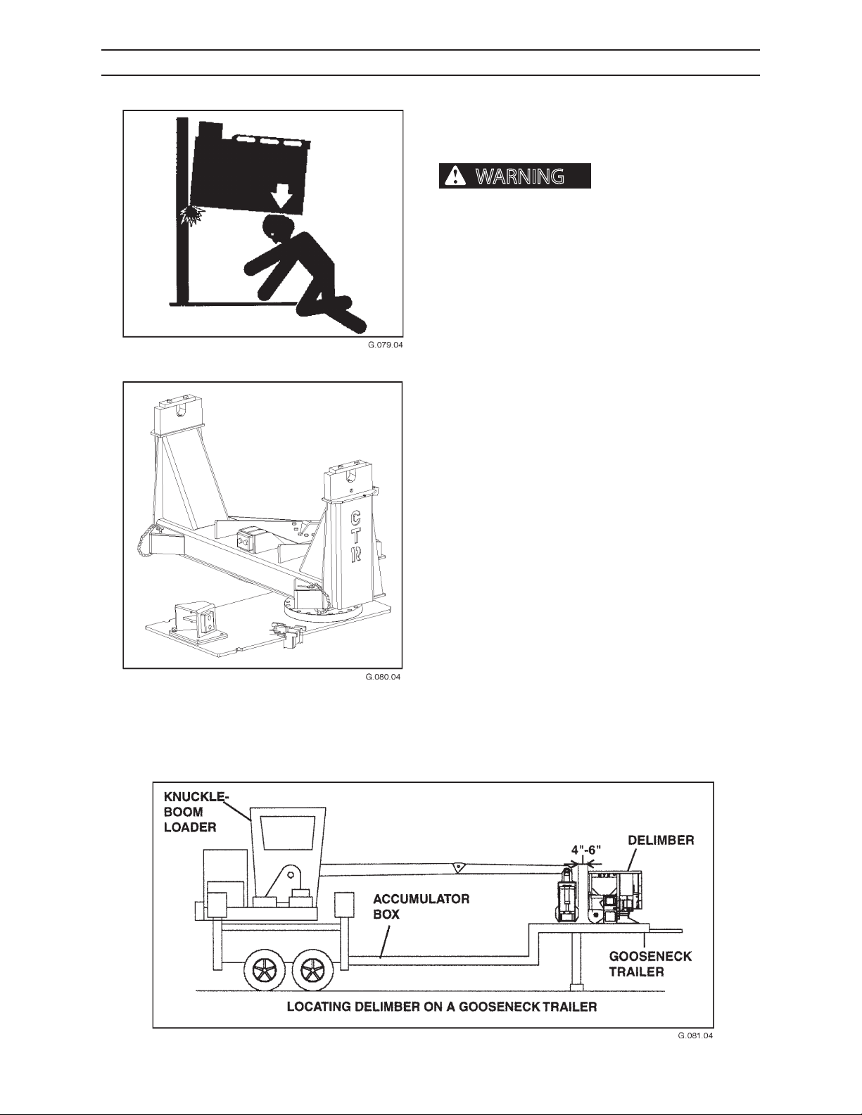
The cradle mount sub-base is connected to the delimber by a pivot block cover bolted down on both sides.
POSITIONING DELIMBER ON A GOOSENECK
TRAILER
When positioning a delimber on a gooseneck trailer,
the delimber roller should be 4-6 inches (10-15 cm)
away from the grapple when the knuckleboom is
fully extended. Leaving a gap between the roller and
grapple keeps the grapple from hitting and damaging
the roller.
CTR426
43
1008
Page 26
CAUTION
TRANSPORT
CAUTION
SECURING
CHAINS
OPERATION
SET UP, CONTINUED
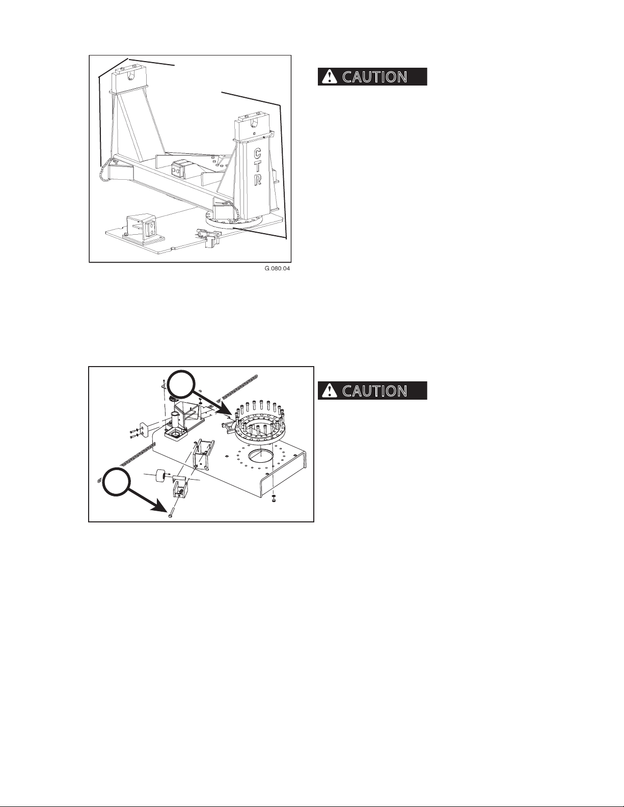
When transporting the
delimber, the cradle is secured to the sub-base with
transport-securing chains. These transport-securing
chains MUST be removed from the cradle before operating the delimber. If the chains are not removed,
the delimber head cannot rotate freely, which may
result in damage to the cradle mount and the delimber.
A
A
10081430.04
ADJUSTING ROLLERS
Failure to check and adjust
rollers and rotation bearing will result in failure of
the rotation bearing and the bolts that attach the
rotation bearing to the cradle base. The cradle can
also be damaged.
To adjust rollers
1. Locate support roller adjustment bolts (A) be-
neath the roller mounting brackets.
2. Adjust the roller to make contact. Turn the bolt
clockwise to raise the roller, and counterclockwise
to lower the roller.
3. Adjust until snug contact of rollers with bottom of
cradle occurs.
CTR426
44
1008
Page 27
OPERATION
Deck
Area
Deck
Area
(Tree
Length)
Deck
Area
Truck Trailer
Delimber
Slasher
Loader
Loader
Trailer
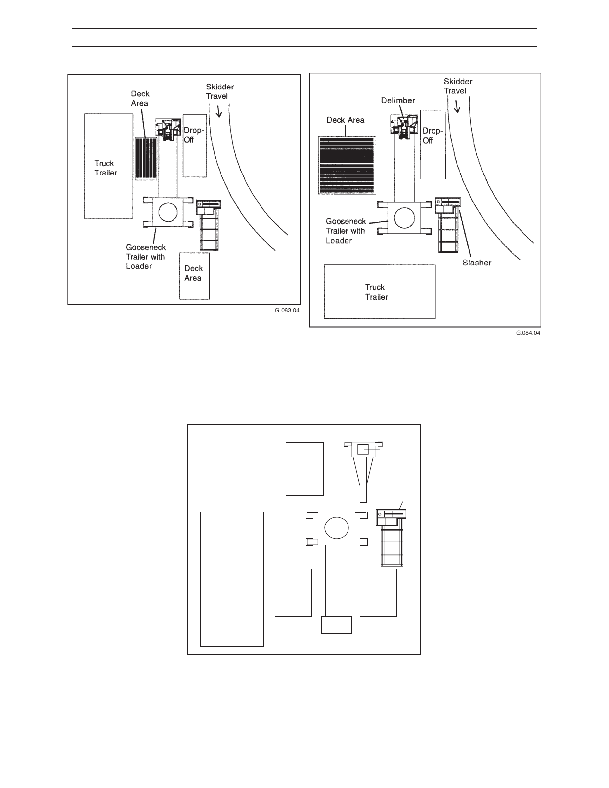
TYPICAL LANDING SET UPS
Cut-to-Length Set Up
Tree Length Set Up
CTR426
Tagalong Set Up
45
1008
Page 28
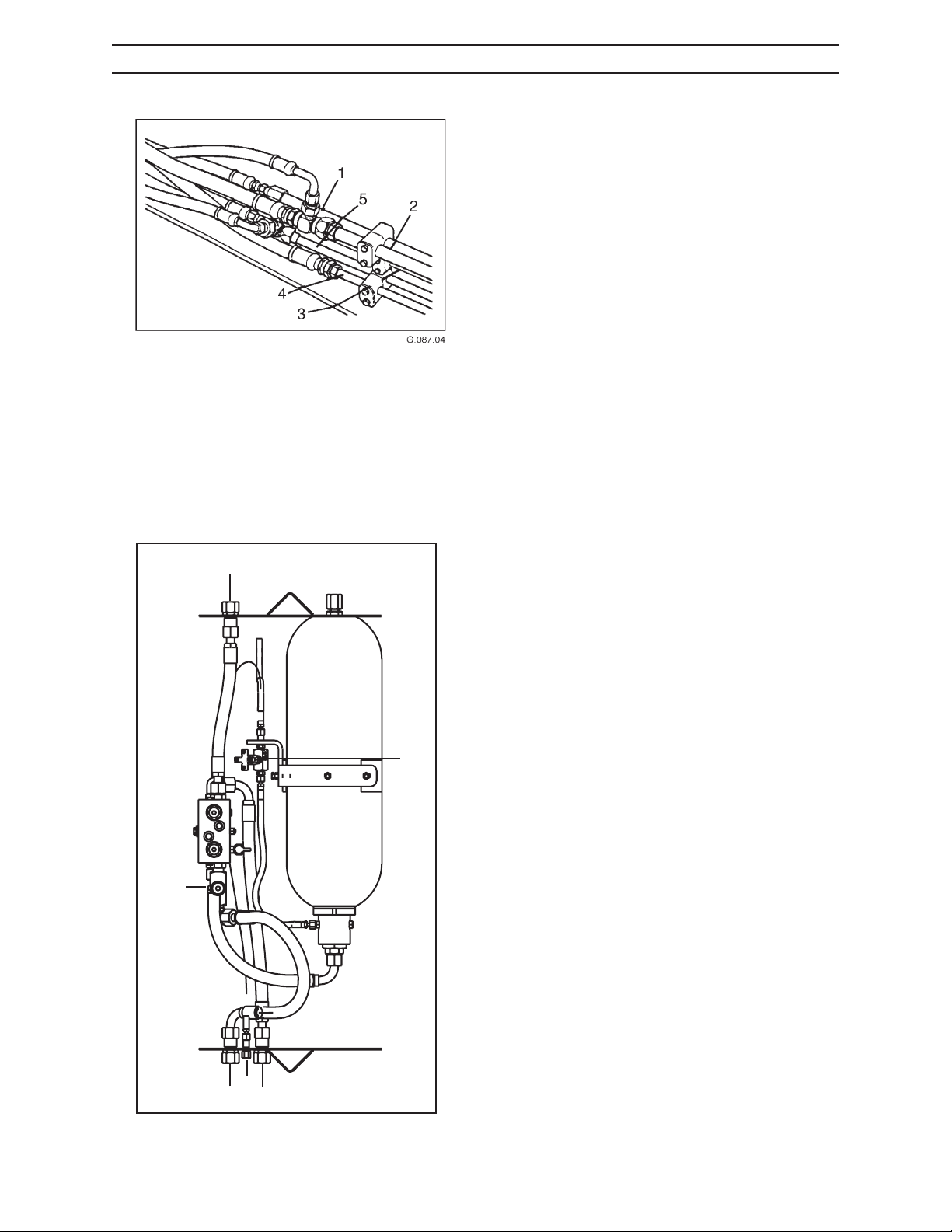
HYDRAULIC CONNECTIONS
CONNECTIONS TO DELIMBER HEAD
1. Saw Pressure
2. Return
3. Saw Bar Up
4. Open Knife Arm Blades
OPERATION
GOOSENECK TRAILER
The conguration on the left is typical for delimbers
mounted on a gooseneck trailer with a loader. The 5
hydraulic hoses from the delimber head (not shown)
are labeled for connection to the 5 hose ttings from
the trailer.
5. Close Knife Arm Blades
1
5
For delimbers mounted on a loader or trailer, remove
the accumulator box cover to access ports that supply
hydraulic pressure to operate the delimbing blades
and topping saw. The ports are numbered in the drawing and listed below:
Description
1. To knife arm open (loader).
2. To return line (loader).
6
3. To delimber knife open.
4. To delimber knife close.
5. Knife open speed control valve.
6. Accumulator drain valve.
CTR426
2
4
3
46
1008
Page 29
OPERATION
NOTICE
NOTICE
HYDRAULIC CONNECTIONS, CONTINUED
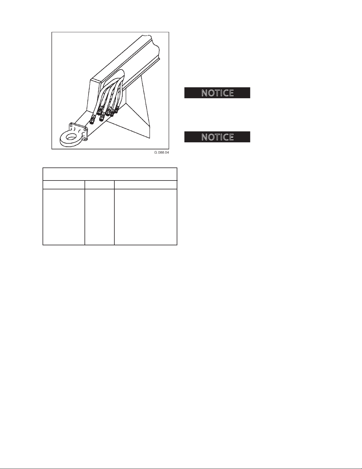
TAGALONG TRAILER CONNECTIONS
LABEL SIZE CONNECTS TO
TAGALONG TRAILER
The conguration on the left is typical for delimbers
mounted on tagalong trailers. The 4 hydraulic hoses
from the delimber head (not shown) are labeled for
connection to the 4 hose ttings from the trailer. The
two 3/8-inch lines are used for air brake lines. See the
chart on the left for hydraulic line labeling.
Incorrectly connected
hydraulic hoses from the delimber head to the mounting unit can cause the knife arm blades and topping saw
functions to operate incorrectly and may cause damage
to hydraulic components.
Warranty may be voided if
hydraulic hoses are damaged due to incorrect hookup.
Tank 1-inch Return
Block 3/4-inch Open/Close Knives
Motor 3/4-inch Saw Pressure
Bar Up 1/2-inch Saw Bar Up
Air Brake (2) 3/8-inch Air Brake Lines
CTR426
47
1008
Page 30
OPERATION
NOTICE
WARNING
WARNING
TOPPING SAW OILER
BLEEDING THE TOPPING SAW OILER SYSTEM
topping saw oil tank is full.
The topping saw oiler system must be bled of air any
time the system runs dry. To rell and bleed the topping saw oiler system, follow the steps on page 4-9.
pressure can penetrate skin and cause severe
personal injury or death. Wear eye and personal
protection equipment (PPE)!
Always use a board or cardboard when checking oil
hoses, lines, and ttings for leaks, cracks, or defects.
Be sure all clamps are in their proper position and
torqued as required and specied. Be sure hoses are
not twisted or touching parts.
DO NOT use hands to search for leaks. Escaping uids
can penetrate skin and enter the bloodstream. Before
disconnecting lines, relieve all pressure.
Before operating, make sure
Fluids escaping under
DO NOT apply pressure to a damaged hose, line, or
tting.
If ANY uid is injected beneath the skin, seek medical
attention immediately. A serious infection or reaction can result without proper medical treatment.
Always close delimber
knives before shutting the unit down. Failure to do
so could result in serious injury or death.
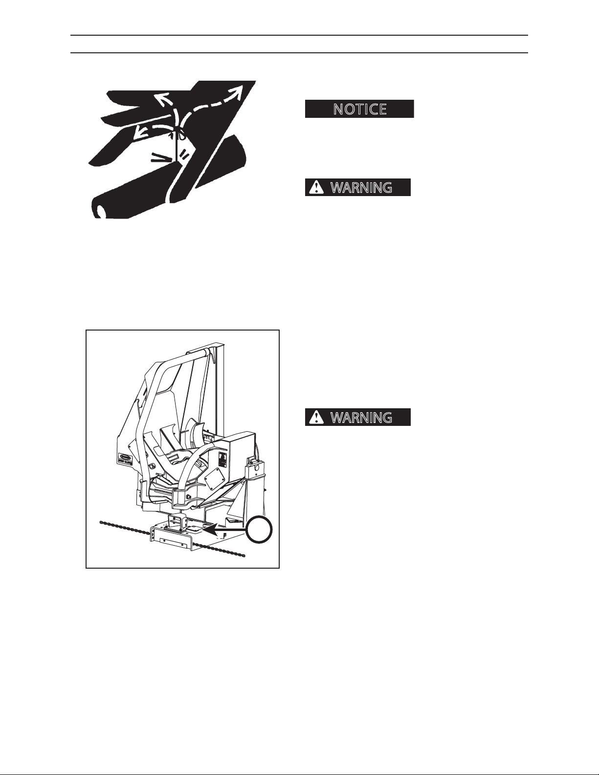
The topping saw oiler provides pressure to the bar
and chain oiler line, feeding chain oil into the saw bar
groove. The topping saw oil tank ller cap is located on
the left side of the delimber base, under topping saw
oiler access door (A).
A
G151.05
The topping saw oil tank capacity is 8.4 gallons (31.75
L). It has been lled with 2 gallons (7.5 L) of bar and
chain oil at the factory, and the topping saw oiler has
been bled and tested.
Caterpillar Forest Products recommends the use of bar
and chain oil because it not only penetrates the saw
chain rivet holes, but also resists being thrown o the
CTR426
48
1008
Page 31
OPERATION
WARNING
NOTICE
TOPPING SAW OILER, CONTINUED
chain.
ber knives before shutting unit down. Discharge
accumulator after shutting unit down and before
performing any maintenance, adjustments or service to the delimber.
Shut engine down, turn key to OFF position and
A
10085OP.05
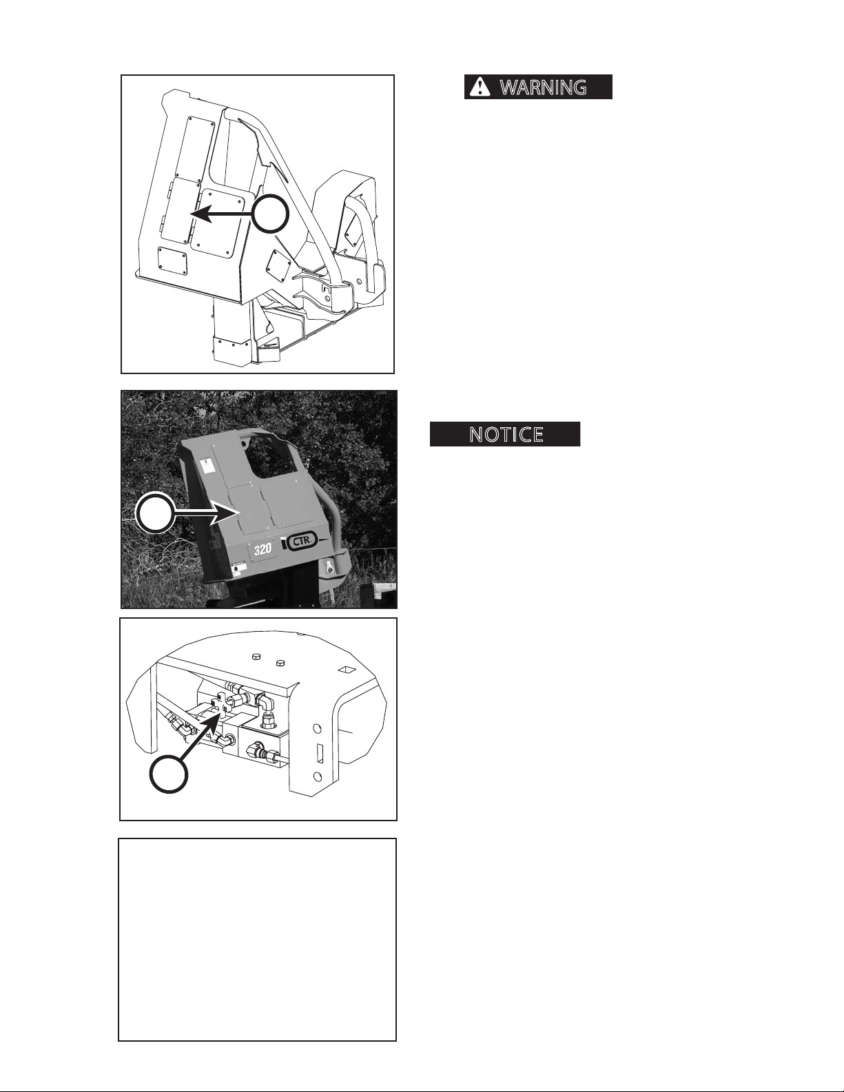
remove key before bleeding the topping saw oiler
system.
1. Remove cover (A) on left side of base.
2. Locate the topping saw oiler.
3. Open needle valve (B), to fully open position.
4. Start engine.
5. Operate BAR DOWN function 3-4 times.
6. Check to see that saw bar and chain are receiving
oil.
7. Shut engine down.
not receiving oil, shut engine down, check oil level
and repeat steps 3-6.
Always close delim-
If the saw bar and chain are
A
8. Close needle valve (B) to the fully closed position.
9. Turn needle valve 1 1/2 turns counter clockwise.
B
100815062OP.05
CTR426
49
1008
Page 32
OPERATION
CAUTION
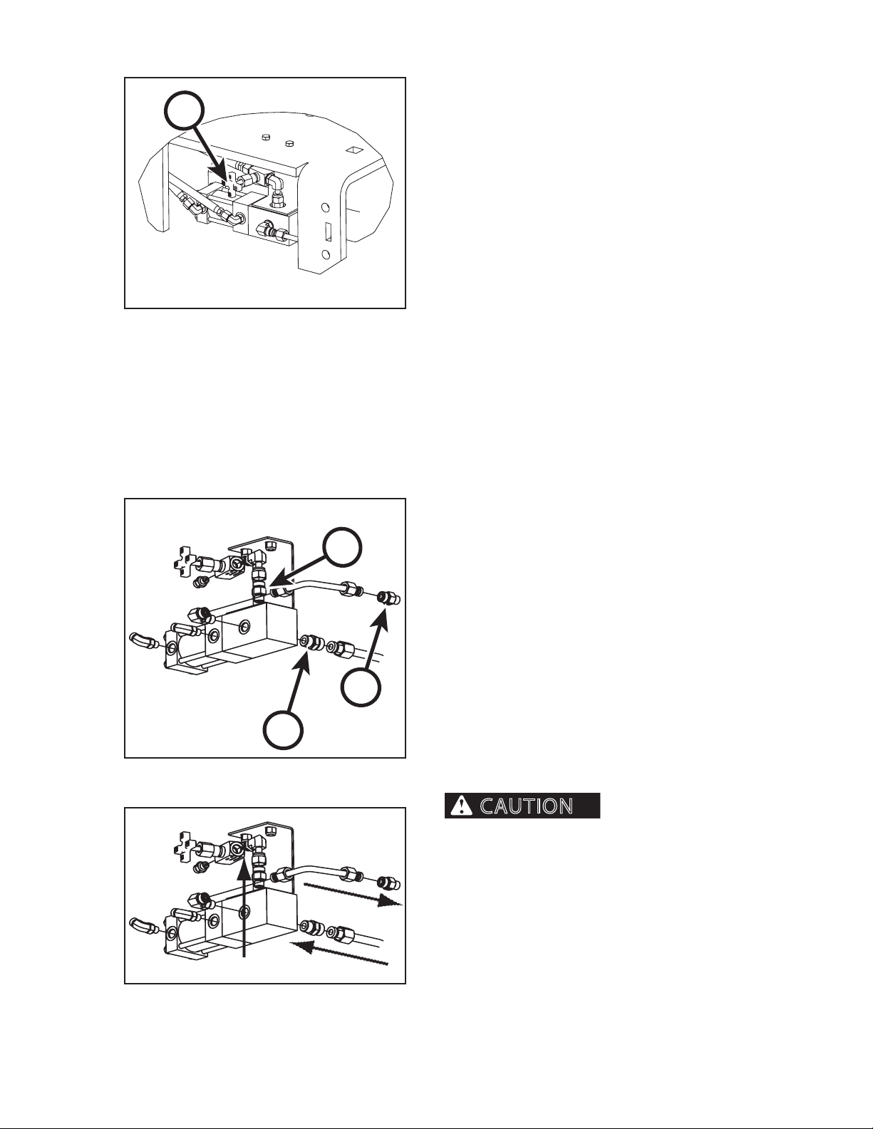
BAR OIL FLOW ADJUSTMENT
A
Caterpillar Forest Products bar and chain oilers are
designed for years of trouble-free operation. To adjust
the oil ow to the bar and chain, follow this procedure:
1. Turn the ow needle valve (A) clockwise to RE-
DUCE oil ow to the bar and chain; counterclockwise to INCREASE oil ow to the bar and chain.
100815062.04
BAR OIL FLOW ADJUSTMENT TROUBLESHOOTING
D
B
C
1008150622.04
If the oiler stops applying oil to the bar and chain:
1. Check oil level in tank; add if necessary.
2. Bleed the system if necessary (see previous).
3. Turn the ow needle valve counterclockwise as
needed to increase oil ow.
4. Check for leaks.
5. Examine check valves (B, C & D):
a. Remove check valves individually from the
oiler system.
b. Clean or replace check valve
d. Reassemble oiler system noting the ow
direction stamped on check valves.
e. Bleed system (see previous).
Installing check valve
in the wrong location or with the ow direction
reversed can cause damage to the oiler system or
personal injury.
1. Check valves are stamped with an arrow.
2. Install according to diagram at left.
CTR426
1008150622.04
410
1008
Page 33
OPERATION
WARNING
WARNING
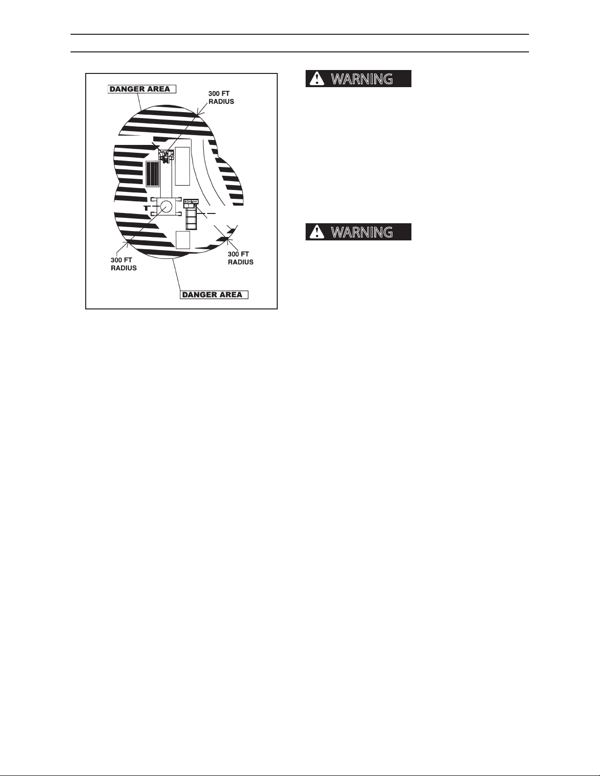
CHARGING THE ACCUMULATOR
danger area of all personnel before any operation
can begin. Failure to do so may result in serious
personal injury or death.
Operator must clear the
DELIMBER
LOADER
SLASHER
GROUND SAW
G.070.04
To ensure proper operation of knife arm blades, accumulator must be fully charged. Engine must be
running to charge accumulator.
Start engine. From loader cab, OPEN and HOLD the
knife arm blades for 2 minutes. The accumulator is now
fully charged.
Always close delimber
knives before shutting unit down. Discharge
accumulator after shutting unit down and before
performing any maintenance, adjustments or
service to the delimber.
CTR426
411
1008
Page 34
OPERATION
WARNING
NOTICE
JOYSTICK BUTTON FUNCTIONS
knives before shutting unit down. Discharge accumulator after shutting unit down and before performing any maintenance, adjustments or service
to the delimber.
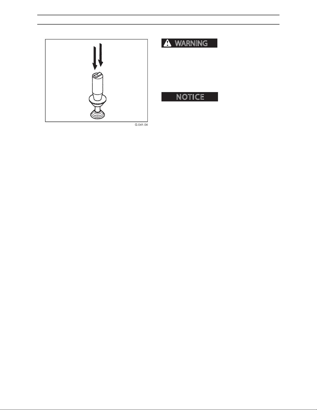
If equipped with joysticks, functions are typically as
follows:
instructions if joystick does not have a rocker switch.
LEFT HAND JOYSTICK ROCKER SWITCH
The left hand joystick rocker switch closes and opens
delimber blades.
To CLOSE delimber blades, depress LEFT side of rocker
switch.
To OPEN delimber blades, depress RIGHT side of rocker
switch.
Always close delimber
Follow loader operation
RIGHT HAND JOYSTICK ROCKER SWITCH
The right hand joystick rocker switch moves the topping saw bar UP and DOWN.
To move topping saw bar DOWN, depress LEFT side of
rocker switch.
To move topping saw bar UP, depress RIGHT side of
rocker switch.
CTR426
412
1008
Page 35
OPERATION
WARNING
WARNING
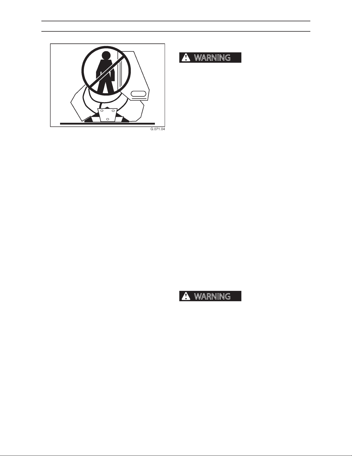
REMOVING TRAPPED LIMBS FROM KNIVES
DELIMBER BLADE SAFETY
Charged accumulator can
close delimber blades resulting in severe personal
injury or death. DO NOT enter the delimber area
without closing delimber blades, shutting engine
down, discharging accumulator and blocking out
tilting in delimber base frame.
FIRST ATTEMPT
1. Remove tree from delimber.
2. Open and close delimber knives to dislodge any
trapped limbs.
3. If this does not clear the trapped limbs, follow
instructions under Second Attempt.
SECOND ATTEMPT
1. Remove tree from delimber.
2. Open knives as far as possible.
3. Run tree back and forth through the open knives
several times to dislodge any trapped limbs.
4. If this does not clear the trapped limbs, go on to
the Third Attempt.
THIRD ATTEMPT
1. Remove tree from delimber.
2. Close knives.
3. Turn loader OFF.
4. Discharge accumulator.
Delimber knives are extremely sharp and will cause severe personal injury
or death.
5. DO NOT ENTER delimbing area if the knives are
still open or partially open because knives will
close once the trapped limbs are removed.
6. Either provide a stable work platform around the
delimber attached to its mounting unit.
CTR426
7. DO NOT ENTER THE DELIMBER KNIFE AREA!
8. Using a rod or similar object, push the trapped
limbs and debris from the knife area.
413
1008
Page 36
OPERATION
CAUTION
NOTICE
Accumulator
Bleed Valve
Pressure
Gauge Port
Knife Arm Blade
Open Cartridge
Knife Arm Blade
Close Cartridge
Knife Arm Open
Speed Control
Cartridge
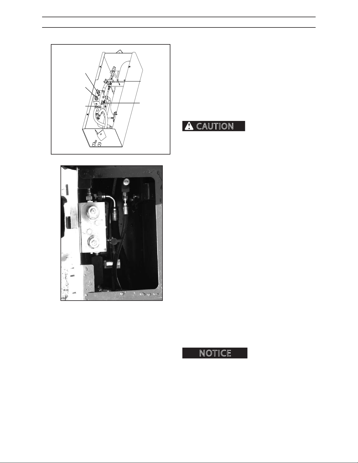
HYDRAULIC SYSTEM ADJUSTMENTS
Delimber hydraulic system adjustments are initially set
by an authorized dealer. If additional adjustments are
required, contact an authorized dealer for assistance,
or follow the instructions outlined here.
Additional ne tuning of the initial settings may be
necessary to optimize performance for a particular
application. Adjustments to the two hydraulic circuits
are required.
The saw circuit controls the saw motor, the bar and
chain oiler and lowers the saw bar.
ow rate of the color coded motor to the loader ow
rate:
Gray - LF (low ow 35-55 gpm)
G.152.02
Black - SF (standard ow 55-90 gpm)
Failure to properly match attachment motor ow
rate to loader ow rate will result in motor failure.
The bar up circuit raises the saw bar and reloads the
bar and chain oiler.
Make sure to match the
There are 6 adjustments that can be made to the delimber to suit the application:
1. Knife arm blade open pressure.
2. Knife arm blade close pressure.
3. Bar down pressure.
4. Bar up pressure.
5. Bar down speed.
6. Auto tensioner pressure.
PREPARING TO MAKE ADJUSTMENTS
Before making any hydraulic adjustments, thoroughly
clean area, record (write down) the current settings of
the ow control valves and pressure valve. The ow
control (color ow) valves have knurled knobs with
color bands to use as a guide for recording the current
settings. Also record the number of turns required to
initially open or close any valve.
Adjustments should be
made AFTER the completion of a cycle, allowing the
person adjusting the valves to observe bar up and down
movements.
Use the following guide for ow control and needle
valves while making adjustments:
OPEN - counterclockwise
CLOSE - clockwise
CTR426
414
1008
Page 37
OPERATION
NOTICE
NOTICE
Accumulator
Bleed Valve
Pressure
Gauge Port
Knife Arm Blade
Open Cartridge
Knife Arm Blade
Close Cartridge
Knife Arm Open
Speed Control
Cartridge
HYDRAULIC SYSTEM ADJUSTMENTS, CONTINUED
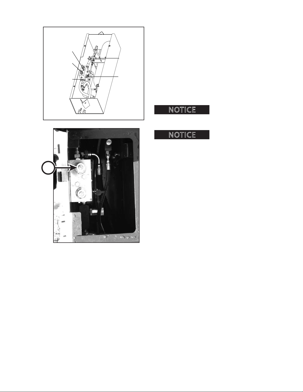
BEGINNING ADJUSTMENTS
1. Loosen the jam nuts on the knife arm blade open
and the knife arm blade close cartridge valves.
2. Using an allen (hex) wrench, turn both cartridge
valves all the way open (counterclockwise). Record
how many complete revolutions it takes to turn
each valve all the way open.
3. Turn the cartridge valves all the way closed, and
then open them 2 complete turns.
Now it is possible to make adjustments designed for
specic timber processing environments.
open/close system pressure above the recommended set-
G.152.02
tings can cause knife arm tubes to break.
pressure adjustment must be set before setting the blade
close pressure.
Setting the knife arm blade
. The knife arm blade open
A
ADJUSTING KNIFE ARM BLADE OPEN PRESSURE
This procedure requires 2 people. Refer to the diagram
on the left for component terminology.
To perform these steps, locate the pressure gauge
port on the manifold block. Remove the plug from the
pressure gauge port and install a pressure gauge with
a rating of 0-3000 psi (0-20,685 kPa).
1. Start the engine.
2. Open the knife arm blades, keeping the knife arm
open button depressed.
3. Turn the adjustment screw (A) clockwise to de-
crease the knife arm blade open pressure.
4. Turn the adjustment screw counterclockwise to
increase the knife arm blade open pressure.
5. The knife arm blade open pressure should be
adjusted to 1500 psi (10,335 kPa). Do not adjust
pressure outside the pressure range.
6. Tighten the jam nut on the knife arm blade open
cartridge valve.
7. Release the knife arm blade open button.
CTR426
415
1008
Page 38
OPERATION
NOTICE
Accumulator
Bleed Valve
Pressure
Gauge Port
Knife Arm Blade
Open Cartridge
Knife Arm Blade
Close Cartridge
Knife Arm Open
Speed Control
Cartridge
HYDRAULIC SYSTEM ADJUSTMENTS, CONTINUED
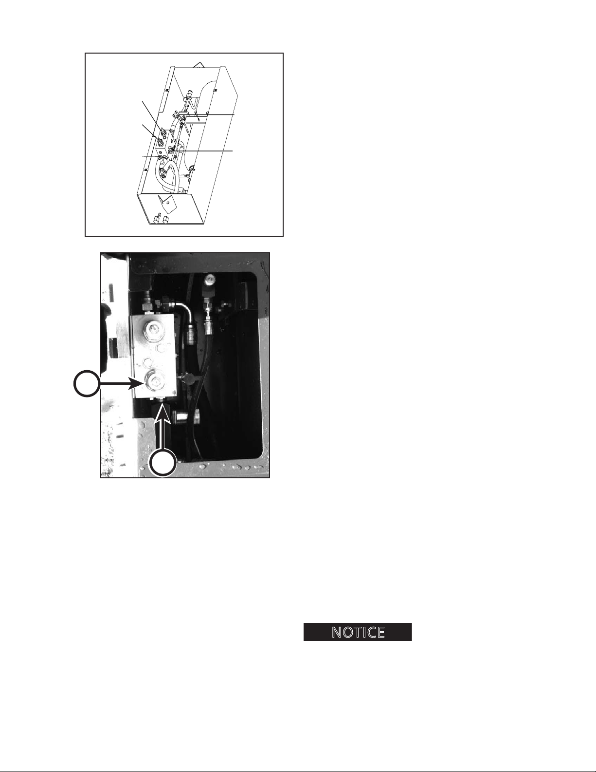
KNIFE ARM BLADE CLOSE PRESSURE
To perform these steps, locate the pressure gauge port
on the manifold block. Discharge the accumulator.
Clean area around the plug, remove the plug from the
pressure gauge port and install a pressure gauge with
a rating of 0-3000 psi (0-20,685 kPa).
1. Start the engine.
2. Loosen the jam nut (A) on the knife arm blade
close cartridge valve.
3. Open the delimber knife arms until the accumula-
tor is fully charged. (See instructions for charging
the accumulator in this section.)
4. Close the delimber knife arm blades.
A
B
G.152.02
5. Adjust the knife arm blade close pressure to
600 psi (4134 kPa).
6. The pressure reading will slowly fall and stop at
the setting of the knife close cartridge valve.
7. Turn the adjustment screw counterclockwise to
decrease the knife arm blade close pressure and
repeat steps 3-6.
8. Turn the adjustment screw clockwise to increase
the knife arm blade close pressure and repeat
steps 3-6.
9. The knife arm blade close pressure should be
adjusted to 600 psi (4134 kPa). Do not adjust pressure outside the pressure range.
10. If the pressure reading is too low, turn the adjust-
ment screw clockwise to increase the knife arm
blade close pressure, and repeat steps 3-5.
11. Tighten the jam nut on the knife arm blade close
cartridge valve.
KNIFE ARM BLADE OPEN SPEED
1. Locate knife arm blade speed control valve (B).
CTR426
2. Loosen set screws.
3. Turn the control valve knob counterclockwise to
increase the knife arm open speed.
4. Turn the control valve knob clockwise to decrease
the knife arm blade open speed.
5. After obtaining desired speed, tighten set screws.
Knife arm blade close speed
is not adjustable.
416
1008
Page 39
OPERATION
NOTICE
NOTICE
Accumulator
Bleed Valve
Pressure
Gauge Port
Knife Arm Blade
Open Cartridge
Knife Arm Blade
Close Cartridge
Knife Arm Open
Speed Control
Cartridge
HYDRAULIC SYSTEM ADJUSTMENTS, CONTINUED
Saw Bar Down
Pressure
Cartridge
SN DE22088 AND LOWER
Saw Bar Down
Pressure
Cartridge
SN DE22089 AND HIGHER
Saw Bar Up
Pressure
Cartridge
Saw Bar Down
Speed Cartridge
10081756.05
Saw Bar
Down Speed
Cartridge
Saw Bar Up
Pressure
Cartridge
10045.OPS.06
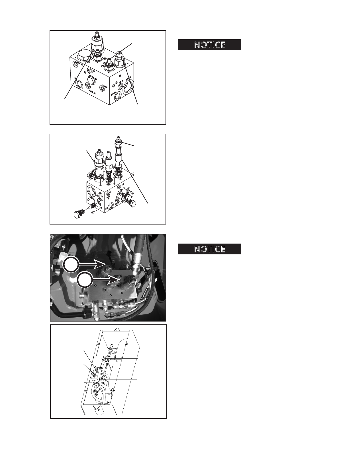
SAW BAR UP PRESSURE ADJUSTMENT
Adjusting the saw bar up
pressure too high will cause the saw bar to slam into the
saw box.
The saw bar up pressure is controlled by the pressure
reducing valve (A) located in the pressure reducing
block.
1. Clean area around gauge port in pressure reduc-
ing block.
2. Install a 0-3000 psi (0-20,685 kPa) pressure
gauge in the gauge port of the pressure reducing
block.
3. Start the power source.
4. Check that the pressure adjustment screw (B)
on the bar down pressure cartridge valve is fully
backed out.
5. Activate the valve to raise the saw bar.
6. Adjust the saw bar up pressure cartridge valve so
that it reads 1800 psi (5,512 kPa).
7. Tighten jam nut on the saw bar up pressure car-
tridge valve.
COMPLETING THE PROCESS
Be sure to tighten set screws on ow control (color
ow) valves, and the jam nuts on the cartridge valves.
CTR426
B
A
G.152.02
Adjusting the saw bar up
pressure too low will cause the delimber knifes to drift
shut.
417
1008
Page 40
OPERATION
NOTICE
CAUTION
NOTICE
Accumulator
Bleed Valve
Pressure
Gauge Port
Knife Arm Blade
Open Cartridge
Knife Arm Blade
Close Cartridge
Knife Arm Open
Speed Control
Cartridge
HYDRAULIC SYSTEM ADJUSTMENTS, CONTINUED
Saw Bar Down
Pressure
Cartridge
SN DE22088 AND LOWER
Saw Bar Down
Pressure
Cartridge
SN DE22089 AND HIGHER
Saw Bar Up
Pressure
Cartridge
Saw Bar Down
Speed Cartridge
10081756.05
Saw Bar
Down Speed
Cartridge
Saw Bar Up
Pressure
Cartridge
10045.OPS.06
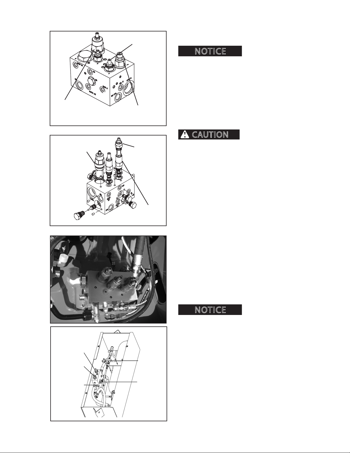
SAW BAR DOWN PRESSURE ADJUSTMENT
Adjusting the saw bar down
pressure too high will cause excessive bar wear.
The bar down pressure can be increased or decreased
to adjust for the type of timber being harvested and
for the operator’s skill level. The objective is to create a
consistent bar down speed as the bar travels through
the wood during cutting.
If the power source cannot provide the correct ow to
the delimber, contact an authorized dealer for additional information.
Make sure to match the
ow rate of the color coded motor to the loader ow
rate:
Gray - LF (low ow 35-55 gpm)
Black - SF (standard ow 55-90 gpm)
Failure to properly match attachment motor ow
rate to loader ow rate will result in motor failure.
This procedure requires 2 people. Refer to the diagram
on the left for component terminology.
1. Clean area around gauge port in pressure reduc-
ing block.
2. Install a 0-3000 psi (0-20,685 kPa) pressure gauge
in the gauge port of the pressure reducing block.
3. Start the engine.
4. Check that the pressure adjustment screw on
the bar down pressure cartridge valve (A) is fully
backed out.
5. Activate the valve to lower the saw bar (saw bar
may not come out of the box) and hold the switch
while reading the bar down pressure from the saw
bar down pressure gauge.
Bar down pressure must not
exceed 650 psi (4482 kPa) or severe damage to the
hydraulic motor will occur.
6. While the loader operator raises and lowers the
saw bar, adjust the bar down pressure cartridge
valve by closing it in 1/4 turn increments until the
pressure gauge reads the new bar down pressure
number, between 400-600 psi (2758-4137 kPa).
CTR426
G.152.02
418
1008
Page 41
OPERATION
NOTICE
Accumulator
Bleed Valve
Pressure
Gauge Port
Knife Arm Blade
Open Cartridge
Knife Arm Blade
Close Cartridge
Knife Arm Open
Speed Control
Cartridge
HYDRAULIC SYSTEM ADJUSTMENTS, CONTINUED
Saw Bar Down
Pressure
Cartridge
SN DE22088 AND LOWER
Saw Bar Down
Pressure
Cartridge
Saw Bar Up
Pressure
Cartridge
Saw Bar Down
Speed Cartridge
10081756.05
Saw Bar
Down Speed
Cartridge
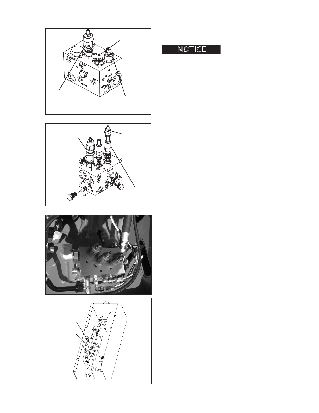
SAW BAR DOWN PRESSURE ADJUSTMENT, CONT.
Optimum bar down pressure
is 550 psi (3790 kPa).
7. Tighten the jam nut on the bar down cartridge
valve.
COMPLETING THE PROCESS
Be sure to tighten set screws on ow control (color
ow) valves, and the jam nuts on the cartridge valves.
SN DE22089 AND HIGHER
Saw Bar Up
Pressure
Cartridge
10045.OPS.06
CTR426
G.152.02
419
1008
Page 42
NOTICE
SN DE22088 AND LOWER
Flow Control
Valve
OPERATION
HYDRAULIC SYSTEM ADJUSTMENTS, CONTINUED
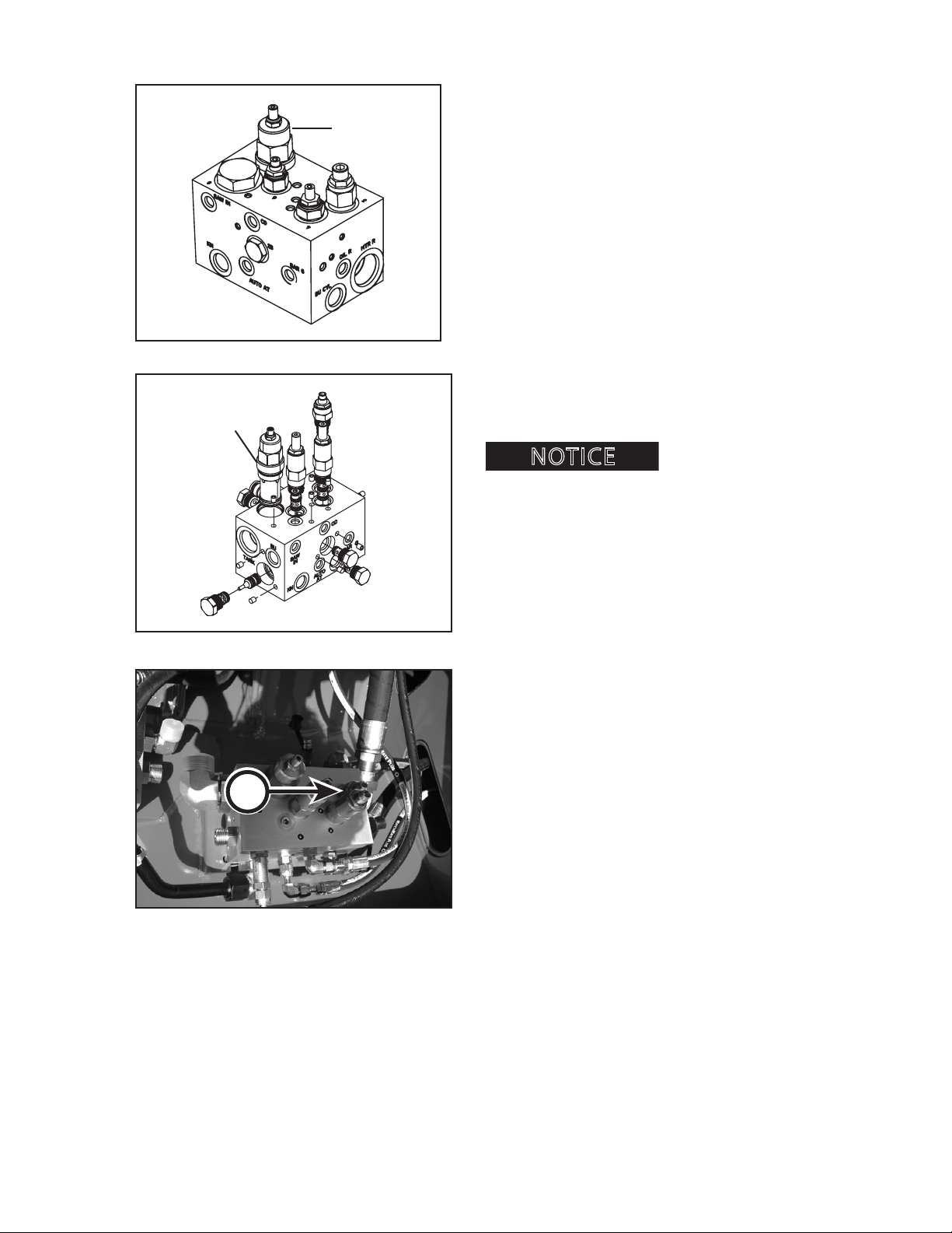
SAW BAR UP SPEED ADJUSTMENT
Flow Control
Valve
The saw bar up speed is controlled by adjusting the
saw bar up control valve. The saw bar up valve controls
the amount of pressure supplied to the bar up cylinder.
To increase the saw bar up speed, turn the ow control
valve (A) clockwise.
To decrease the saw bar up speed, turn the ow control valve counterclockwise.
1. Start the engine.
2. Raise and lower the saw bar 3 times to stabilize
10081756.05
the system.
3. While the loader operator raises and lowers the
saw bar, a second person must adjust the bar
up speed control valve until the bar raises in 1-2
seconds total travel time.
too fast can cause the chain to come o the saw bar.
Setting the saw bar up speed
A
COMPLETING THE PROCESS
Be sure to tighten set screws on ow control (color
ow) valves, and the jam nuts on the cartridge valves.
10045.OPS.06
CTR426
420
1008
Page 43
OPERATION
NOTICE
HYDRAULIC SYSTEM ADJUSTMENTS, CONTINUED
Auto Tensioner
Pressure Valve
SN DE22088 AND LOWER
Auto Tensioner
Pressure Valve
10081756.05
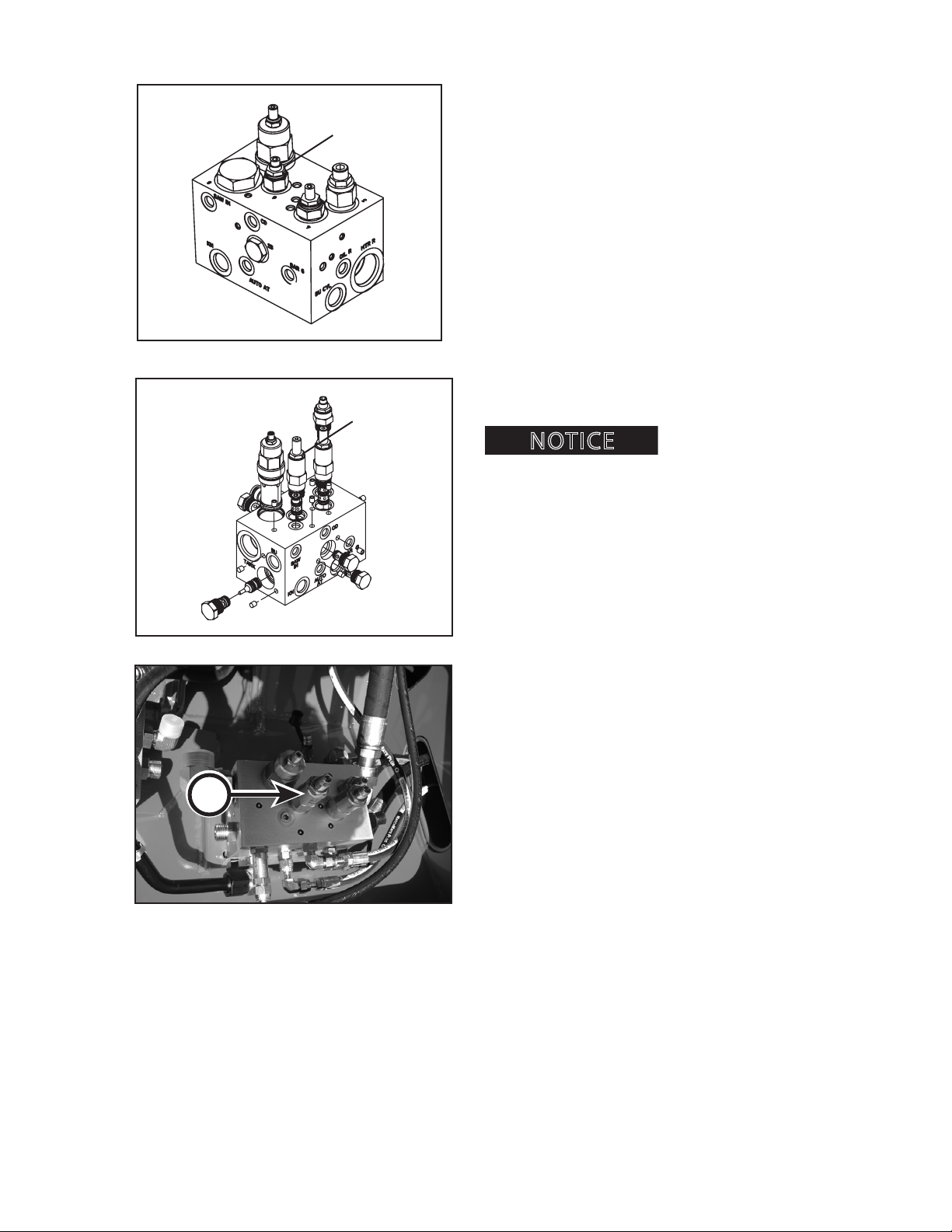
AUTO TENSIONER PRESSURE ADJUSTMENT
The auto tensioner pressure is controlled by adjusting
the auto tensioner pressure control valve. The auto
tensioner pressure meters the hydraulic pressure applied to the auto tensioner.
To increase the auto tensioner pressure, turn the ow
control valve (A) clockwise.
To decrease the auto tensioner pressure, turn the ow
control valve counterclockwise.
1. Start the engine.
2. Raise and lower the saw bar 3 times to stabilize
the system.
3. While the loader operator raises and lowers the
saw bar, a second person must adjust the auto
tensioner pressure until correct setting is reached.
Setting the auto tensioner
pressure too high can cause the chain to break. Setting
the auto tensioner pressure too low can cause the chain
to come o the saw bar. Auto tension pressure must not
exceed 400 psi (2756 kPa) or severe damage or excessive
wear to the saw bar and chain will result.
A
10045.OPS.06
COMPLETING THE PROCESS
Be sure to tighten set screws on ow control (color
ow) valves, and the jam nuts on the cartridge valves.
CTR426
421
1008
0206
Page 44
WARNING
WARNING
A
OPERATION
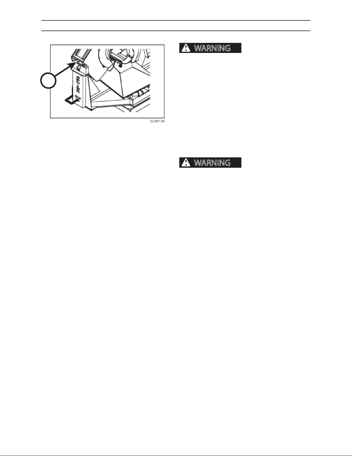
DETACHING THE DELIMBER
Always discharge the accumulator before performing any maintenance or
service on the delimber.
DO NOT detach the delimber for transport. Only
detach the delimber for maintenance or service purposes. Delimbers can be transported when mounted
on their bases.
When detaching the delimber, always use a lifting
harness. Lifting harnesses are available at authorized
dealers.
To prevent equipment damage or personal injury,
when lifting the delimber, use the lifting harness. Another line should be secured to the delimber to help
balance the delimber while it is being lifted.
Equipment damage,
severe personal injury or death can occur if the
delimber is mishandled or dropped. Do not stand
near or under the delimber head while it is being
lifted.
PROCEDURE FOR DETACHING DELIMBER
1. Turn engine o.
2. Remove key.
3. Discharge accumulator (see instructions in this
section).
4. Relieve pressure from hydraulic reservoir.
5. Find hydraulic lines located under access cover on
base.
6. Disconnect and cap both ends of all hydraulic
lines.
7. Disconnect and cap both ends of all bar oiler lines.
8. Remove bolts and pivot blocks (both sides) (A).
9. Using a lifting harness, lift delimber head slightly,
making sure hydraulic lines are not tangled or in
any way preventing the unit from being lifted o
the supports.
10. Lift delimber head until it is clear of the mounting
cradle.
CTR426
422
1008
Page 45
OPERATION
WARNING
WARNING
DISCHARGING ACCUMULATOR
DELIMBER BLADE SAFETY
close delimber blades resulting in severe personal
injury or death. DO NOT enter the delimber area
without closing delimber blades, shutting engine
down, discharging accumulator and blocking out
tilting in delimber base frame.
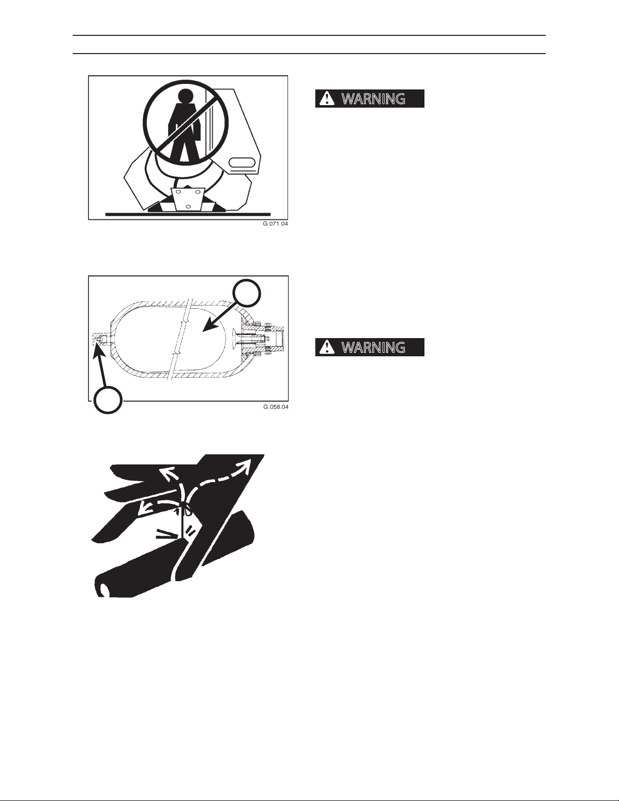
The accumulator cylinder contains a bladder (A). Accumulator pressure is set by pumping nitrogen gas into
the bladder through the nitrogen charge and check
port (B).
DISCHARGING THE ACCUMULATOR
Delimbers mounted on a loader or trailer have hydraulic oil pressure that must be bled from the accumulator
A
before performing any maintenance or disconnecting
any hydraulic lines. If this is not done, the system will
discharge oil under pressure when lines are disconnected or parts are removed.
Charged accumulator can
B
Fluids escaping under
pressure can penetrate skin and cause severe
personal injury or death. Wear eye and personal
protection equipment (PPE)!
Always use a board or cardboard when checking oil
hoses, lines, and ttings for leaks, cracks, or defects.
Be sure all clamps are in their proper position and
torqued as required and specied. Be sure hoses are
not twisted or touching parts.
DO NOT use hands to search for leaks. Escaping uids
can penetrate skin and enter the bloodstream. Before
disconnecting lines, relieve all pressure.
DO NOT apply pressure to a damaged hose, line, or
tting.
If ANY uid is injected beneath the skin, seek medical
attention immediately. A serious infection or reaction
can result without proper medical treatment.
CTR426
423
1008
Page 46
OPERATION
Accumulator
Bleed Valve
Pressure
Gauge Port
Knife Arm Blade
Open Cartridge
Knife Arm Blade
Close Cartridge
Knife Arm Open
Speed Control
Cartridge
DISCHARGING THE ACCUMULATOR, CONTINUED
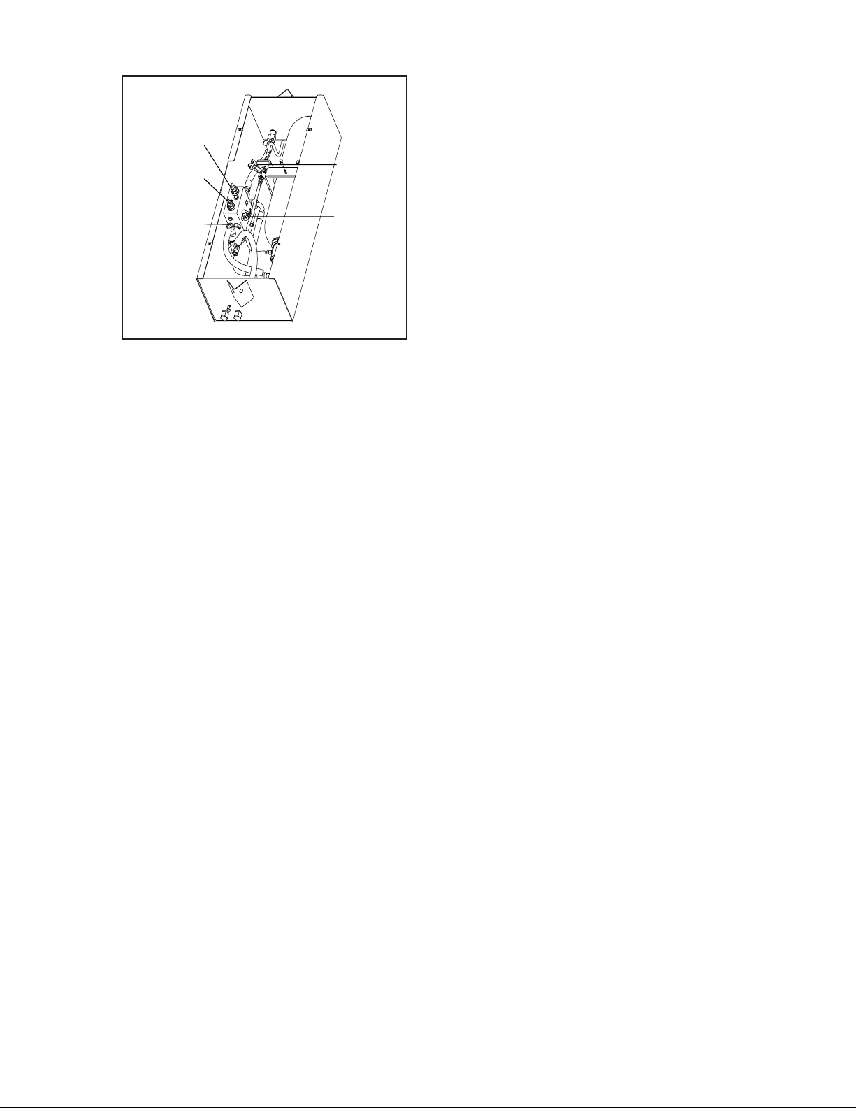
To bleed pressure from the accumulator,
1. Make sure engine is OFF.
2. Open bleed valve in accumulator box by turning
3. Give the accumulator 45 seconds to bleed o
The accumulator bleed valve must be closed for
operation.
G.152.02
the bleed valve handle counterclockwise.
pressure. In a quiet area, the bleed o will be
audible.
CTR426
424
1008
Page 47
LUBRICANTS
NOTICE
LUBRICANTS
HYDRAULIC OIL
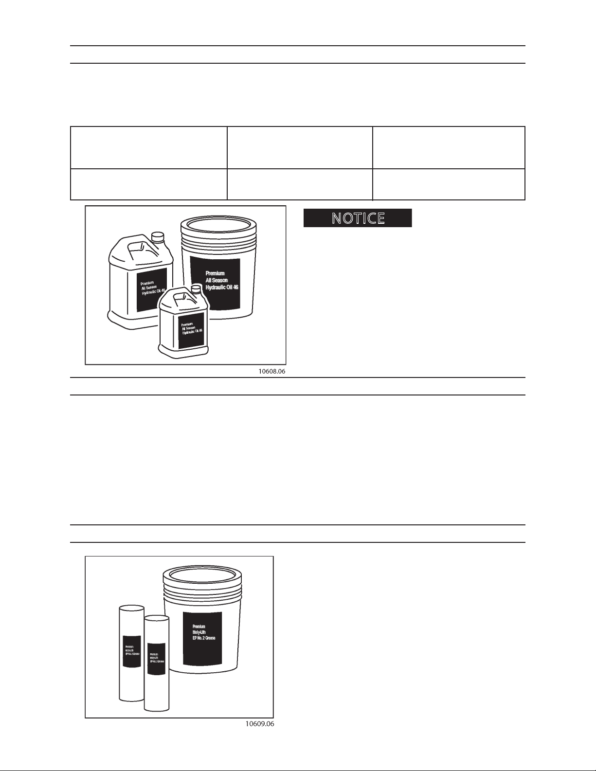
Hydraulic systems have been factory-lled with Premium All-Season Hydraulic Oil 46. Use the following hydraulic
oils for the specicied ambient temperature range.
AMBIENT TEMP AMBIENT TEMP AMBIENT TEMP
25°F TO 80°F 10°F TO 95°F 0°F TO 105°F
32°C TO 27°C 23°C TO 35°C 18°C TO 41°C
Premium All-Season Premium All-Season Premium All-Season
Hydraulic Oil 32 Hydraulic Oil 46 Hydraulic Oil 68
Check with an authorized
dealer for hydraulic fulid recommendations and compatibilities.
Be sure hydraulic uid selection is compatible with the
hydraulic system.
Be sure hydraulic uid selection assistance comes from
a reputable dealer.
Be sure hydraulic specications meet or exceed Premium All-Season Hydraulic Oil specications. See an
authorized dealer.
Be sure to use a mineral-base hydraulic oil.
TOPPING SAW OIL
The topping saw oil tank capacity is 8.4 gallons (31.75
L). It has been factory-lled with 2 gallons (7.5 L) of bar
and chain oil. recommends the use of bar and chain
oil because it penetrates the saw chain rivet holes and
resists being thrown o the chain.
GREASE
All lubricating points use Premium Moly-Lith #2
grease. Use Premium Moly-Lith #2 when lubricating.
CTR426 1008
51
Page 48
LUBRICANTS
NOTICE
STORING LUBRICANTS
Store lubricants in a clean area that will keep them protected from water, dirt or other contamination.
Always use clean containers when handling lubricants.
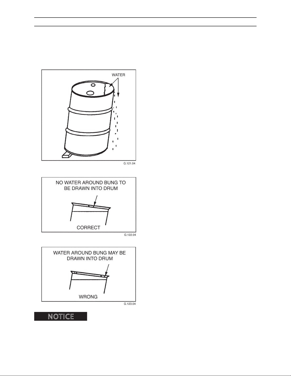
Storing lubricant drums or other containers outdoors is a poor practice. To minimize the harmful eect of unavoidable outdoor storage, a few simple precautions and procedures can be very helpful.
1. Generally, lubricants in containers smaller than
drums (55, 30 and 16 gallon oil drums and 400 and
120 pound grease drums) should never be stored
outdoors. When drums must be stored outdoors, a
temporary shelter or lean-to, or a waterproof tarp
will protect them from rain or snow.
2. Drums should be placed on their sides with the
bungs approximately horizontal. In this position,
the bungs are below the level of the contents
so that breathing of water or moisture is greatly
reduced, and water cannot collect inside the
chine (ridge of drum). For maximum protection,
the drums should be stood on end with the bung
ends down on a well-drained and contained surface. Where all of these approaches are impractical, drum covers can be used. These are available
in metal and plastic.
3. When drums must be stored outdoors with the
bung end up, they should be blocked up with the
bungs parallel to the block to keep water away
from the bung openings.
4. Drums that have a bung on the side should be
stored either on end, or on their side with the
bung down. Regardless of their position, drums
should always be placed on blocks or racks several
inches o the ground to avoid moisture damage.
DISPOSE OF USED FLUIDS PROPERLY.
(such as salt air or industrial pollution), apply Chrome Kote Corrosion Preventive with a sponge to portions exposed to
air. See Storage section for more information.
CTR426
If machine will be stored for an extended period, or stored in a corrosive environment
52
1008
Page 49
MAINTENANCE SAFETY
WARNING
NOTICE
MAINTENANCE SAFETY
BEFORE MAINTENANCE
Maintaining this delimber improperly could result in severe personal injury or
death. Read this manual before performing maintenance. Follow all safety instructions.
Most maintenance procedures described in this section require 2 people. As an added
safety precaution, it is always advisable to have a second person available during any maintenance procedure.
1. Read all safety and maintenance instructions in
this operator’s manual.
2. Position equipment on rm, level ground.
3. Shut engine down.
4. Move controls in all directions to relieve hydraulic
pressure.
5. Discharge accumulator.
G.100.05
6. Remove key from ignition.
PRACTICE SAFE MAINTENANCE
Understand service procedures before doing maintenance. When doing maintenance, keep area around
delimber clean and dry.
DO NOT service delimber while it is operating. Keep
away from power-driven parts. Lower attachment to
the ground. Disengage power. Stop the engine. Move
controls in all directions to relieve hydraulic pressure
and to discharge accumulator. Remove key from ignition. Allow machine to cool down.
Support all raised equipment.
Keep all delimber parts in good condition, and be sure
parts are properly installed. Repair delimber damage
immediately. Replace worn or broken parts. Remove
any buildup of grease, oil or debris.
CTR426
Disconnect battery before adjusting electrical system.
61
1008
Page 50
MAINTENANCE SAFETY
WARNING
WARNING
BEFORE MAINTENANCE
DELIMBER BLADE SAFETY
close delimber blades resulting in severe personal
injury or death. DO NOT enter the delimber area
without closing delimber blades, shutting engine
down, discharging accumulator and blocking out
tilting in delimber base frame.
Charged accumulator can
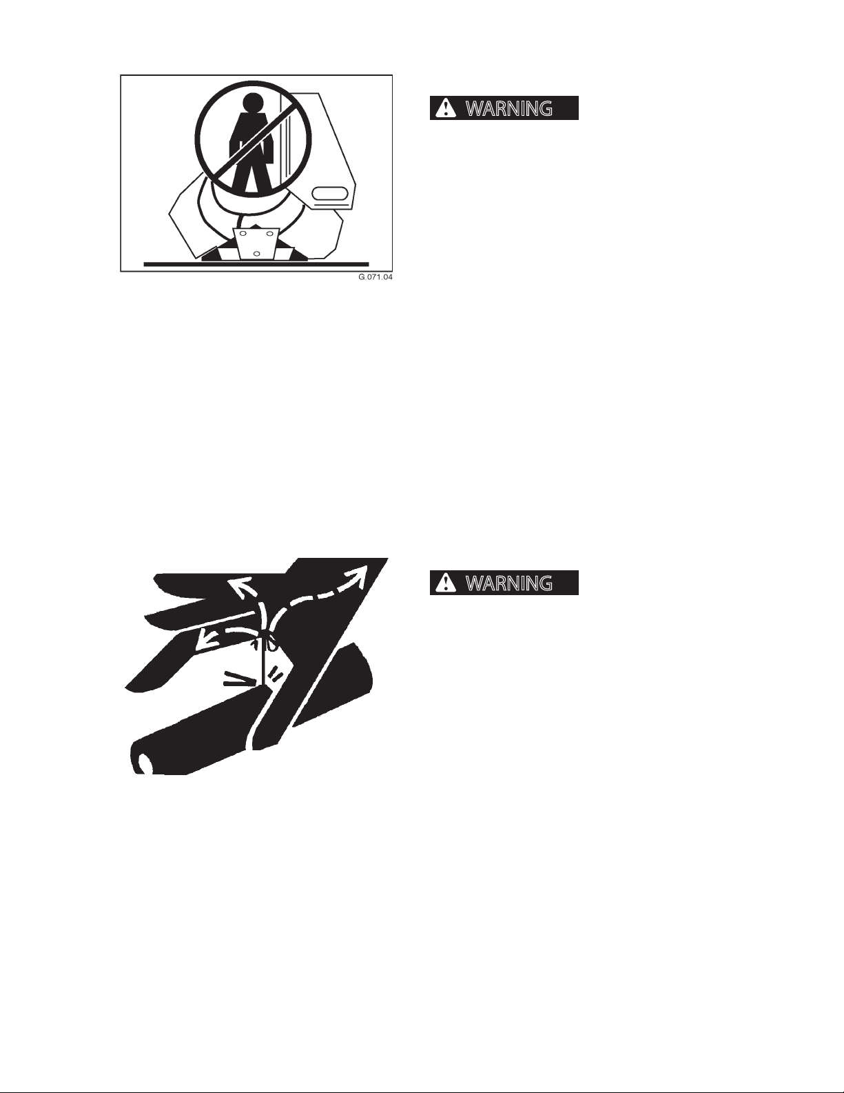
DISCHARGE ACCUMULATOR
Standing or working in
the delimbing knife area or working on the hydraulic system can lead to serious personal injury or
death.
Unless certain that the accumulator is discharged, do
not stand or work in the delimbing knife area.
The accumulator is charged with hydraulic pressure
to close the delimber blades during normal operation. The accumulator can close the delimber blades
without the engine driving the hydraulic pump. Therefore, it is very important that BEFORE entering the
area around the delimber blades, or doing any work
on the hydraulic system, the accumulator MUST be
discharged. If the accumulator is not discharged, the
blades may close.
See Operation section for instructions on discharging
the accumulator.
CTR426
62
1008
Page 51
MAINTENANCE SAFETY
WARNING
WARNING
BEFORE MAINTENANCE
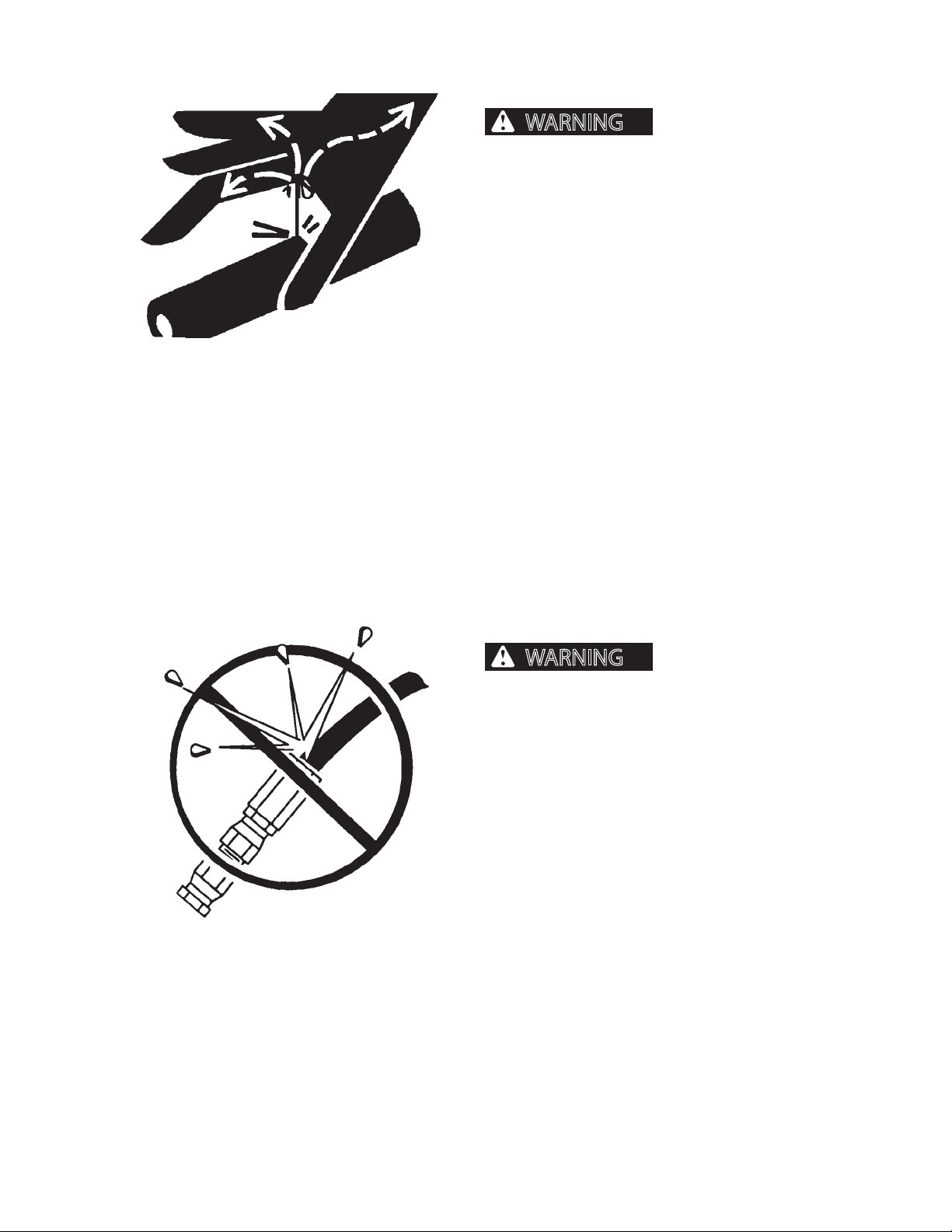
FLUIDS UNDER PRESSURE
pressure can penetrate skin and cause severe
personal injury or death. Wear eye and personal
protection equipment (PPE)!
Always use a board or cardboard when checking oil
hoses, lines, and ttings for leaks, cracks, or defects.
Be sure all clamps are in their proper position and
torqued as required and specied. Be sure hoses are
not twisted or touching parts.
DO NOT use hands to search for leaks. Escaping uids
can penetrate skin and enter the bloodstream. Before
disconnecting lines, relieve all pressure.
DO NOT apply pressure to a damaged hose, line, or
tting.
If ANY uid is injected beneath the skin, seek medical
attention immediately. A serious infection or reaction
can result without proper medical treatment.
Fluids escaping under
HOSES AND FITTINGS
Mismatched brands or
types of hoses and ttings can blow apart and
cause severe personal injury or death.
DO NOT interchange brands or types of hoses and
ttings.
DO NOT install a tting from one manufacturer on a
hose from a dierent manufacturer.
DO NOT install crimp ttings on hoses meant for reusable ttings.
Wear eye and personal protection equipment
(PPE)!
Always use a board or cardboard when checking oil
hoses, lines, and ttings periodically for leaks, cracks or
defects. Be sure all clamps are in their proper position
and torqued as required and specied. Be sure hoses
are not twisted or touching parts.
CTR426
63
1008
Page 52
MAINTENANCE SAFETY
WARNING
WARNING
CAUTION
DURING MAINTENANCE
HOT HYDRAULIC OIL
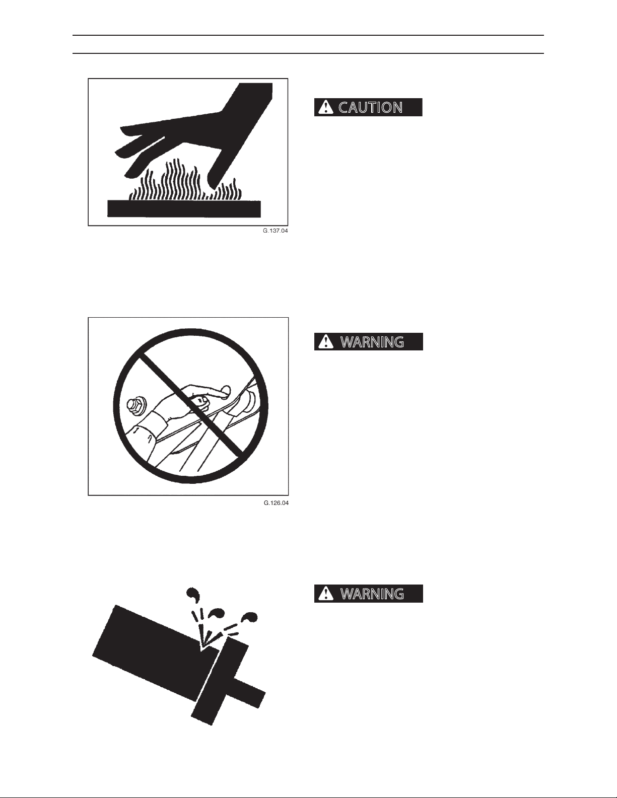
burns. A thermometer is located on the hydraulic
oil tank. DO NOT work on the hydraulic system if oil
temperature exceeds 120°F (49°C).
Hot oil can cause severe
PINCH POINTS
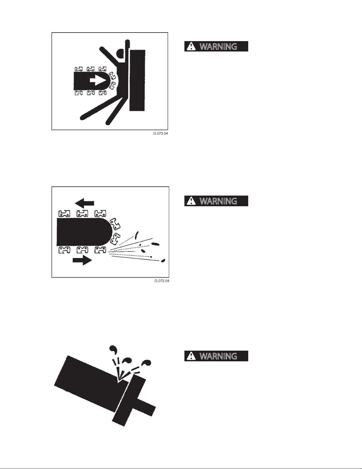
Placing hands or any portion of the body where delimber moves can cause
severe personal injury or death. NEVER place hands
or any portion of the body where injury could occur
if delimber moves. NEVER check pin hole alignments with ngers.
PRESSURE SETTINGS
Excessive hydraulic pressure can cause component or structural failure,
which may result in severe personal injury or
death. Wear eye and personal protection equipment (PPE)!
CTR426
DO NOT exceed factory-adjusted pressure settings.
64
1008
Page 53
MAINTENANCE SAFETY
WARNING
WARNING
WARNING
DURING MAINTENANCE
SAW BAR SAFETY
in the pedestal or delimber can cause the saw bar
to fall. A falling saw bar can cause severe personal
injury or death.
NEVER handle the saw bar when loader is running.
ALWAYS wear personal protection equipment (PPE),
especially gloves, when handling the saw bar.
Loss of hydraulic pressure
SAW OPERATION SAFETY
Flying particles and debris can cause severe injury or death. Keep loader
door closed when operating saw.
To prevent damage from ying debris, align saw bar
away from loader and other equipment. Replace damaged window material.
Do not operate delimber within 300 feet (91 meters) of
personnel or property.
SERVICING CONTROL VALVES, CYLINDERS, PUMPS
AND MOTORS
Increasing relief valve
settings could cause delimber or component failure
resulting in severe personal injury or death. Do not
change pressure settings. Do not switch lines from
one valve to another.
CTR426
Special tools and training are required to service control valves, cylinders, pumps and motors. If these parts
need services, see an authorized dealer.
65
1008
Page 54
MAINTENANCE SAFETY
WARNING
NOTICE
WARNING
DURING MAINTENANCE
SUPPORT COMPONENTS
ber or delimber parts, if a hose breaks or a control
is moved, machine parts such as boom or attachment may fall resulting in serious injury or death.
Provide support for components. DO NOT depend
on hydraulic cylinders for support.
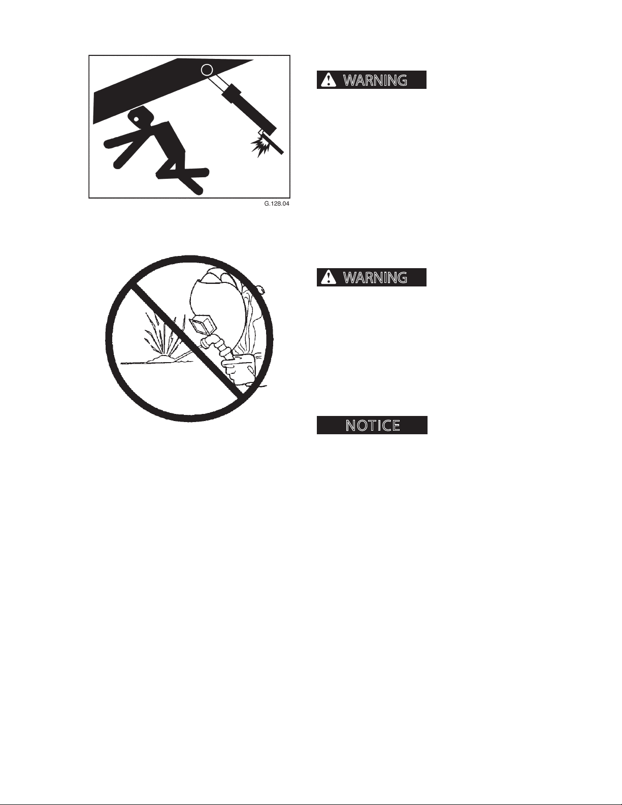
UNAUTHORIZED WELDING
can cause structural failure and/or severe personal
injury or death.
When working on delim-
Unauthorized welding
DO NOT weld on any structural member.
Any unauthorized welding or repair will void
the Warranty.
Once authorized, turn battery disconnect switch OFF
and place welding ground (stinger) as close to the
weld site as possible. Do not allow weld current to pass
through bearings or pivot points.
Welding can cause damage
to the electrical system.
CTR426
66
1008
Page 55
MAINTENANCE SAFETY
AFTER MAINTENANCE
DISPOSING OF WASTE
Follow local, state, federal, and international regulations when disposing of waste. Waste may include, but
is not limited to oil, fuel, coolant, brake uid, lters,
and batteries.
Use leakproof containers when draining uids. Do not
use food or beverage containers. Do not pour waste
on the ground, down a drain, or into any water source.
Clean up all spilled fuel, oil, grease, etc. and dispose of
per local, state, federal, or international regulations.
STORING FLAMMABLE MATERIALS
• Do not smoke where ammable materials are
stored.
• Store fuels and lubricants in properly marked
containers.
• Store oily rags and other ammable materials in
protective containers.
CTR426
67
1008
Page 56

MAINTENANCE SAFETY
NOTES
CTR426
68
1008
Page 57
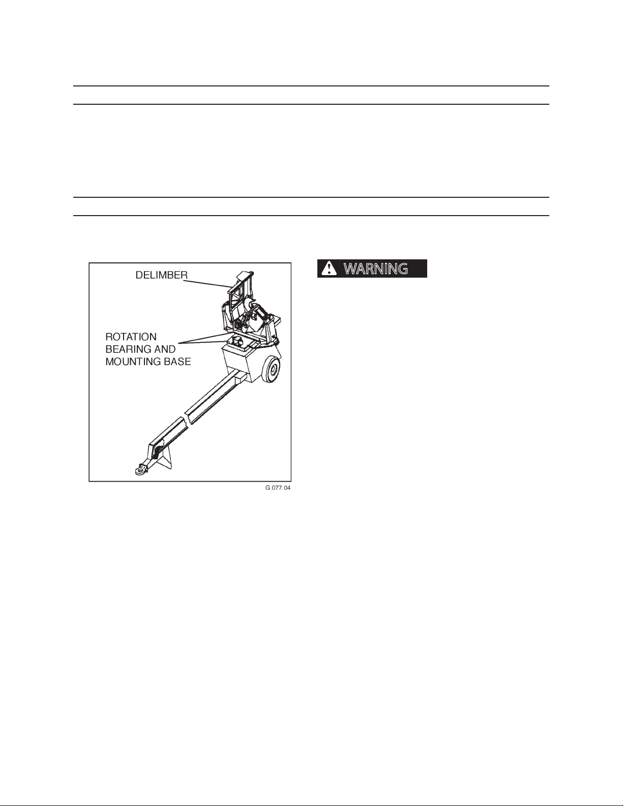
SCHEDULED AND PERIODIC MAINTENANCE SERVICES
WARNING
SCHEDULED AND PERIODIC
MAINTENANCE SERVICES
LUBRICATION NOTICE
Listed maintenance intervals are for normal use applications. When greasing lubrication ttings, if grease is not forced
out of bushing ends with the recommended shots, increase number of shots until grease is forced out. If grease cannot
be forced out, check for blocked grease passageways.
If lubricated areas are dry at the end of a normal operating day, increase frequency of lubricating intervals rather than
increaseing amount of grease used in one lubrication period.
POSITION DELIMBER FOR MAINTENANCE
To avoid serious personal injury or property damage, follow the steps
below before performing any maintenance on this
machine.
1. Shut engine down.
2. Move joystick controls in all directions to relieve
hydraulic pressure and discharge accumulator.
3. Remove key from ignition switch.
CTR426
71
1008
Page 58
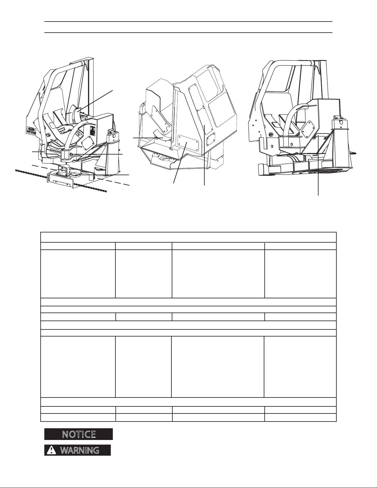
NOTICE
WARNING
14, 18
SCHEDULED AND PERIODIC MAINTENANCE SERVICES
MAINTENANCE CHART
5, 6
15
13
7, 10
14, 18
17
2 , 3, 4, 7, 10
1, 9, 11, 12, 14
Use the KEY # and COMPONENT for locating the proper service and maintenance procedures in this section.
AS REQUIRED
KEY COMPONENT SERVICE SPECIFICATION MATERIAL USED
1. Cylinder Rods Clean and Grease Clean, then apply thin grease coat Prem. Grease
2. Saw Chain Replace See details in section Oregon 11BC or 11H Chain
3. Saw Chain Sharpen See details in section Files
4. Saw Bar Recondition See details in section
5. Delimber Blades Sharpen See details in section Use genuine parts
6. Delimber Blades Replace See details in section Use genuine parts
7. Bar Oil Flow Adjust See details in section
DAILY OR EVERY 10 HOURS
KEY COMPONENT SERVICE SPECIFICATION MATERIAL USED
8. Topping Saw Oiler Fill Check level daily; ll if necessary. Bar and Chain Oil
WEEKLY OR EVERY 50 HOURS
KEY COMPONENT SERVICE SPECIFICATION MATERIAL USED
9. Knife Arm Tubes Lubricate Lubricate until grease is forced out Prem. Grease
10. Topping Saw Cylinder Lubricate Lubricate until grease is forced out Prem. Grease
11. Knife Arm Cylinder Lubricate Lubricate until grease is forced out Prem. Grease
12. Knife Arm Shaft Bearing Lubricate Lubricate until grease is forced out Prem. Grease
13. Feed Roller Shaft Lubricate Lubricate until grease is forced out Prem. Grease
14. Cradle Roller Lubricate Lubricate until grease is forced out Prem. Grease
15. Knife Arm Blades Inspect Inspect for knicks, gaps and rolls.
16. Large Rotation Bearing Lubricate Lubricate with 3-5 shots of grease Prem. Grease
17. Saw Bar Bearing Lubricate Lubricate until grease is forced out Prem. Grease
MONTHLY OR EVERY 250 HOURS
KEY COMPONENT SERVICE SPECIFICATION MATERIAL USED
18. Cradle Roller Adjust See details in section
authorized dealer for diagnosis and repair or replacement.
CTR426
Lubricate with Premium Moly-Lith EP #2 Grease.
Do not weld on structures. Immediately report structural problems (cracks) to an
72
1008
Page 59
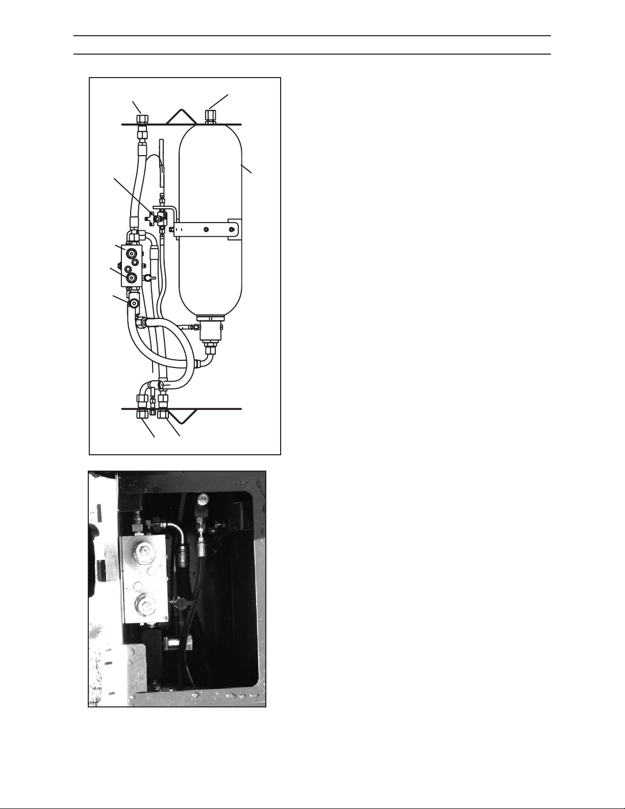
SCHEDULED AND PERIODIC MAINTENANCE SERVICES
HYDRAULIC PRESSURE
For delimbers mounted on a loader or trailer, remove
9
7
1
2
3
4
8
the accumulator box cover to access parts that supply
hydraulic pressure to operate the delimbing blades
and topping saw. The parts are numbered in the drawing and listed below:
Description PSI kPa
1. Nitrogen charge and 315 2172
check port
2. 5-Gallon nitrogen over
hydraulic accumulator
3. Relief cartridge 1700 11.722
for OPEN
4. Relief cartridge 500-700 3448-4827
for CLOSE
5. CLOSE line to
delimber
6. OPEN line to
delimber
7. Safety accumulator
bleed valve
8. Flow control valve
9. Pressure line 2250-3500 15,514-24,133
6
5
G.155.05
CTR426
73
1008
Page 60

SCHEDULED AND PERIODIC MAINTENANCE SERVICES
WARNING
PREPARING FOR SAW BAR AND CHAIN MAINTENANCE
Lowering the topping saw bar by hand can cause severe personal injury or death.
Follow the steps below to perform any chain or bar maintenance.
LOADER MOUNTED DELIMBERS WITHOUT
AUTOBARUP FEATURE
1. Close delimber knives.
2. Depress rocker switch to lower saw bar.
3. Shut loader engine down.
4. Remove key.
5. Discharge accumulator.
6. Perform saw or bar maintenance.
7. Close accumulator bleed valve in accumulator
box.
8. Start loader engine.
9. Depress rocker switch to raise saw bar.
LOADER MOUNTED DELIMBERS WITH AUTOBAR
UP FEATURE
1. Turn toggle switch supplied with auto-bar-up
system to OFF position.
2. Close delimber knives.
3. Depress rocker switch to lower saw bar.
4. Turn loader engine o.
5. Remove key.
6. Discharge accumulator.
7. Perform saw or bar maintenance.
8. Close accumulator bleed valve in accumulator
box.
9. Turn toggle switch to ON position.
10. Start loader engine.
11. Depress rocker switch to raise saw bar.
Keep several chain loops on hand for quick change to save downtime on the job.
Caterpillar Forest Products recommends that chains be trued and sharpened by a saw
CTR426
74
1008
Page 61

SCHEDULED AND PERIODIC MAINTENANCE SERVICES
AS REQUIRED
1. CLEAN AND GREASE CYLINDER RODS
All exposed cylinder rods should be wiped clean when
dirty. After wiping cylinder rods clean, wipe a thin lm
of grease onto the cleaned surfaces.
CTR426
75
1008
Page 62
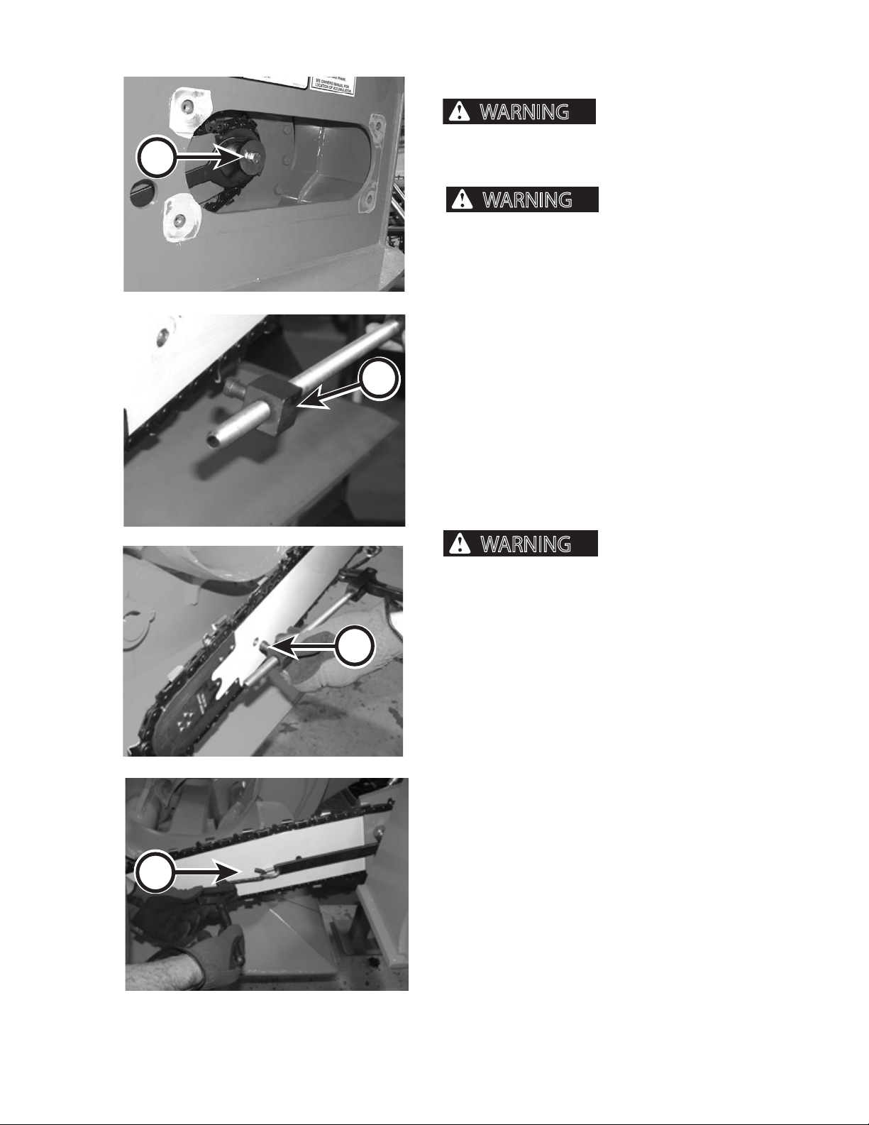
WARNING
A
WARNING
WARNING
SCHEDULED AND PERIODIC MAINTENANCE SERVICES
AS REQUIRED
2. REPLACE SAW CHAIN
Servicing system under
pressure can result in serious personal injury or
death. Always relieve pressure before performing
service.
B
0151.06
141.06
knife arms, turn unit o and discharge the accumulator before performing any maintenance
or service to the delimber. Failure to do so could
result in severe personal injury or death.
Wear eye and personal protection equipment
(PPE)!
1. Lower saw bar.
2. Shut machine down.
3. Remove key.
4. Discharge accumulator.
5. Place collar bar over end of saw bar located in saw
box (A).
6. Insert load binder assembly end (B) into hole on
saw bar (C).
binder assembly is properly engaged in the saw bar
hole before engaging chain removal tool. Failure to
do so could result in severe personal injury.
Always close delimber
Verify that pin on load
D
C
140.06
7. Attach load binder assembly to collar bar (D).
006.06
CTR426
76
1008
Page 63
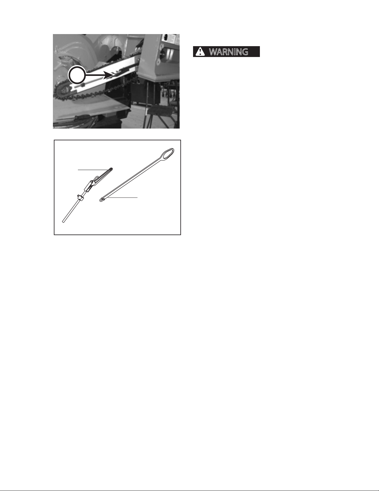
WARNING
E
Load Binder
Assy
SCHEDULED AND PERIODIC MAINTENANCE SERVICES
AS REQUIRED
REPLACE SAW CHAIN, CONT.
pressure can result in serious personal injury or
death. Always relieve pressure before performing
service.
8. Compress saw bar by tightening lever (E) on load
binder assembly.
9. Remove old chain from saw bar and sprocket.
10. Visually inspect saw bar and sprocket for any dam-
age. Replace if damaged.
147.06
11. Lay the new chain out in a loop.
12. Install new chain making sure chain is properly
aligned with the bar and sprocket. If teeth do not
point in the proper direction, op the loop over
and repeat this step.
13. Loosen lever (E) on load binder assembly, remove
chain removal tool.
14. Store chain removal tool in a secure location.
Collar Bar
After the chain has run for approximately 15 minutes,
stop and check the chain tension.
Servicing system under
10083564.06
CTR426
77
1008
Page 64
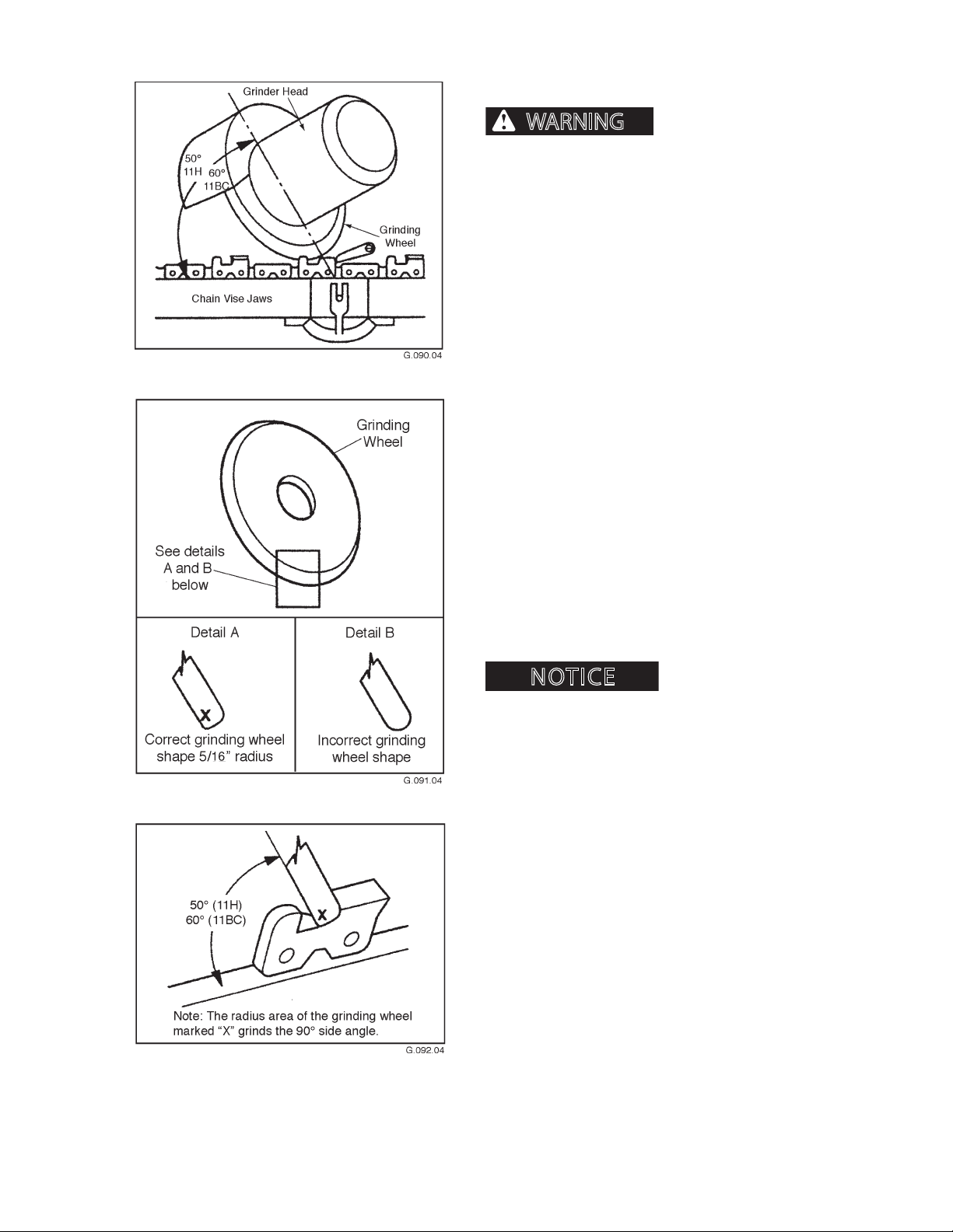
SCHEDULED AND PERIODIC MAINTENANCE SERVICES
NOTICE
WARNING
AS REQUIRED
3. SHARPEN SAW CHAIN
and/or other material can cause severe personal injury or death. Wear personal protection equipment
(PPE) such as a face shield or safety goggles.
Weather, soil and terrain determine how often the
chain requires sharpening. Generally, sharpening is
necessary only once or twice weekly. If the saw strikes
hard foreign objects embedded in logs, extra sharpening may be required.
Filing or cutting chain teeth will shorten teeth and
cause drag teeth to be too long. This will cause the saw
to chatter up and down during operation. To prevent
this, use a at le. Filing one or two strokes on drag
teeth every other sharpening should be sucient.
Although 11BC and 11H type chains may be handled, it is more practical to machine-grind the chain.
Flying debris, tree limbs
MACHINEGRINDING TEETH
Set grinding wheel at 30 degrees for an 11BC chain,
and 40 degrees for an 11H chain to achieve proper top
plate angle.
Tilt grinding wheel 60 degrees for an 11BC and 50 degrees for an 11H chain to vise jaws to achieve proper
side plat angle. Use a maximum 5/16 inch (11 mm)
thick grinding wheel for Oregon 11BC and 11H chains.
Dress grinding wheel often
to maintain correct shape (as shown). Use either rotary
wheel dresser or dressing brick. The radius area of the
wheel marked X grinds the 90 degree side angle.
CTR426
78
1008
Page 65
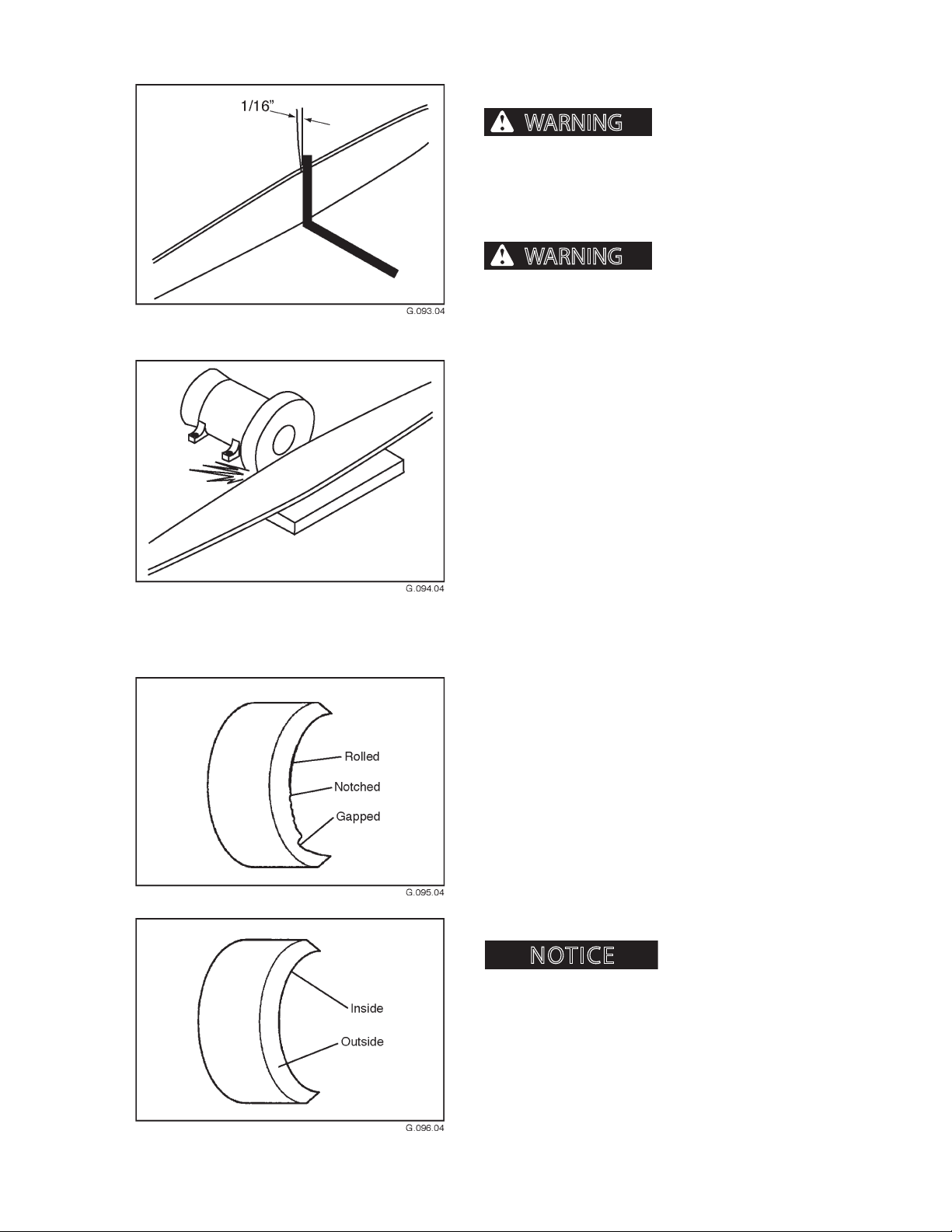
SCHEDULED AND PERIODIC MAINTENANCE SERVICES
NOTICE
WARNING
WARNING
AS REQUIRED
4. RECONDITION SAW BAR
and/or other material can cause severe personal
injury or death. Wear personal protection equipment (PPE) such as a face shield or safety goggles,
leather gloves and protective sleeves at all times
around blades.
knife arms, turn unit o and discharge the accumulator before performing any maintenance or service to the delimber. Failure to do so could result in
severe personal injury or death.
1. Discharge accumulator.
2. Remove chain (see replace saw chain earlier in this
section) and saw bar. After saw bar is removed,
place bar on a smooth, at surface.
3. Place a square against the saw bar. Note the
distance between saw bar and square. If the distance is greater than 1/16 inch (1.5 mm), repair is
needed.
Flying debris, tree limbs
Always close delimber
4. Using a disc sander, grind the rails evenly. Be care-
ful not to distort the normal curve of the saw bar.
5. SHARPEN DELIMBER KNIFE ARM
BLADES
1. Discharge accumulator.
2. Check knife arm blades weekly for gapped, rolled
or notched edges. Small nicks, gaps and rolls can
be easily removed with an 8-inch or 10-inch at
mill bastard le.
3. Sharpen blades as is done for an ax or bladed
cutting tool. The blades are made of an alloy steel
that tends to self-sharpen, causing edges to wear
thin. This may cause edges to roll, dulling the
blades. Blades should need ling once a month.
Do not sharpen knife arm
blades unless absolutely necessary.
CTR426
4. When blades require sharpening, le the outside
to a keen edge using the recommended at le.
After a keen edge is achieved on the outside,
touch up the inside. DO NOT put a heavy sharpening on the inside. Remember, touch up only.
79
1008
Page 66
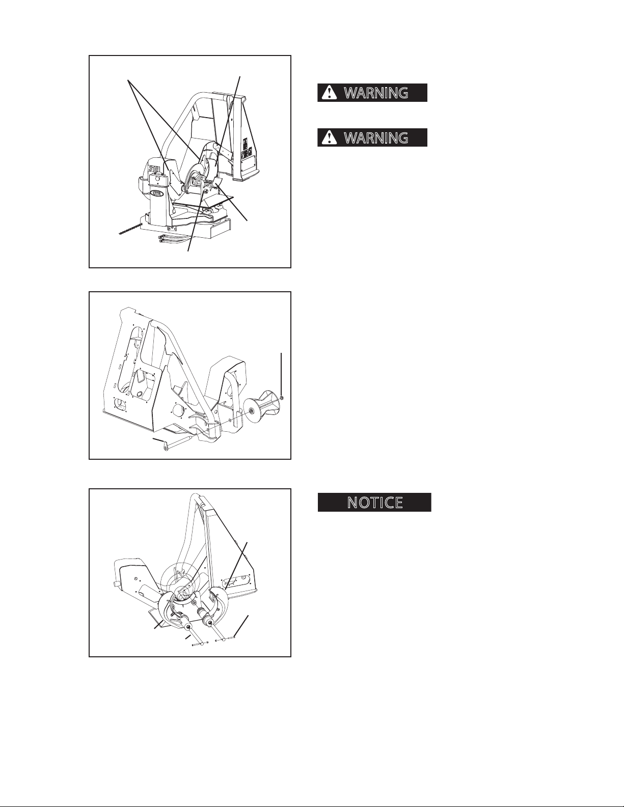
SCHEDULED AND PERIODIC MAINTENANCE SERVICES
NOTICE
WARNING
WARNING
AS REQUIRED
Knife Arm Access Covers
Shaft & Collar
FIG. 1
Blade Arm Assemby
Weldment
Bottom Knife/
Chip Breaker
100822841.05
1 1/2” Roller
Retaining Nut
6. REPLACE DELIMBER KNIFE ARM
BLADES
Equipment damage,
severe personal injury or death can occur if delimber lower blade arms are mishandled or dropped.
Always close delimber
knife arms, turn unit o, block out tilting on base
and discharge the accumulator before performing
any maintenance or service to the delimber. Failure
to do so could result in severe personal injury or
death.
1. Remove knife arm access covers, see Fig. 1.
2. The blade arm assembly to be removed must be
securely supported before proceeding to the next
step. Doing so will ensure the blade arm assembly
does not fall or shift its position when the pivot
shaft is moved.
3. Access knife arm cylinder through the knife arm
access cover. Disconnect grease lines from pin
assembly and knife arm. Disconnect knife arm
cylinder from the damaged blade arm assembly.
Roller Pin
Knife Arm
Assembly
Pivot
Shaft
FIG. 2
FIG. 3
10082284.05
Knife Arm
Assembly
5/8” Bolt &
Nylock Nut
100822871.05
4. Locate shaft collar which is secured to the blade
arm pivot shaft by a 5/8 inch bolt and nylock nut.
The collar is located on the end of the shaft going
through the hole in the bottom knife/chip breaker
weldment. Remove the 5/8 inch bolt and nylock
nut, see Fig. 3.
5. Locate 1 1/2 inch delimber roller retaining nut.
Loosen 1 1/2 inch delimber roller retaining nut
and remove roller pin, see Fig. 2.
The roller must be securely
supported.
6. Remove roller.
7. Drive pivot shaft through hole in the shaft sup-
porting plate located near the roller assembly.
Once the shaft clears the hole located in the weldment wall, it can be pulled through the blade arm
assembly from the opposite end of the shaft.
8. Remove blade arm assembly by sliding the gear
end of the blade arm assembly through the knife
arm access cover.
CTR426
710
1008
Page 67
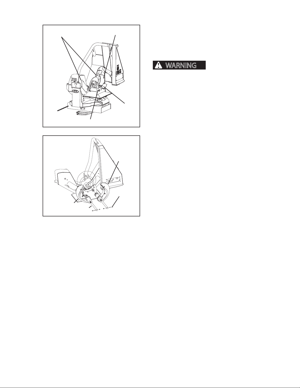
WARNING
Knife Arm Access Covers
SCHEDULED AND PERIODIC MAINTENANCE SERVICES
Shaft & Collar
FIG. 1
Blade Arm Assemby
Weldment
Bottom Knife/
Chip Breaker
100822841.05
AS REQUIRED
6. REPLACE DELIMBER KNIFE ARM BLADES, CON
TINUED
REASSEMBLING DELIMBER BLADE ARMS
(Typical for either right or left arm replacement)
Equipment damage, severe personal injury or death can occur if delimber
lower blade arms are mishandled or dropped.
1. The blade arm assembly must be securely sup-
ported before proceeding. Doing so will ensure
the blade arm assembly does not fall or shift its
position when the pivot shaft is reinstalled.
2. Reinstall blade arm assembly through knife arm
access cover.
3. Slide pivot shaft through hole in bottom knife/
chip breaker weldment, blade arm assembly, and
through appropriate hole in the shaft supporting
plate.
Knife Arm
Assembly
Pivot
Shaft
FIG. 2
Knife Arm
Assembly
5/8” Bolt &
Nylock Nut
100822871.05
4. With arms of both blade arm assemblies open and
resting on timing plates, raise new blade arm assembly.
At this point it should be possible to close and
reopen opposite blade arm assembly without any
restriction of movement. Move to the opposite
side of the unit and raise the newly installed blade
arm assembly. Both blade arm assemblies must be
able to close and reopen without any restrictions.
5. Reconnect knife arm cylinder to blade arm assem-
bly. Reconnect grease line to pin assembly and
knife arm.
6. Reconnect shaft collar, located on the end of the
shaft that goes through hole in bottom knife/chip
breaker weldment. Replace the 5/8 inch bolt and
nylock nut.
CTR426
711
1008
Page 68
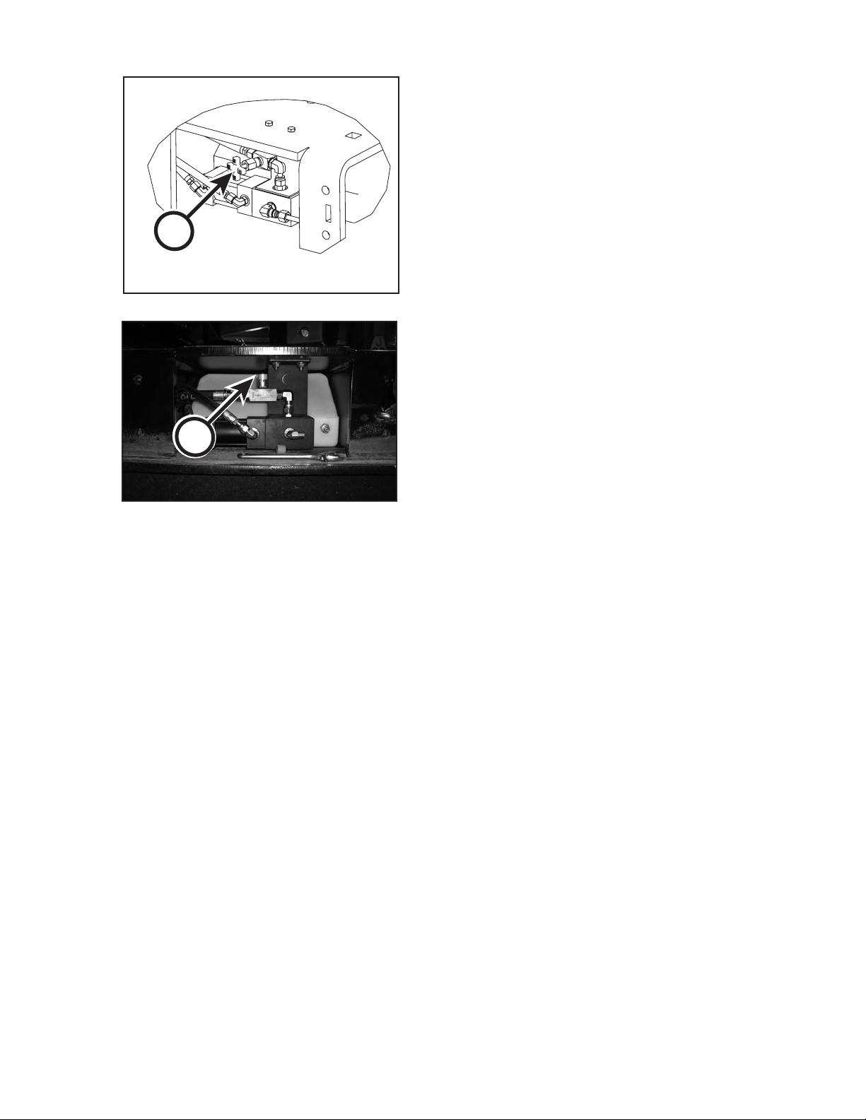
A
SCHEDULED AND PERIODIC MAINTENANCE SERVICES
AS REQUIRED
7. ADJUST BAR OIL FLOW
If it is necessary to adjust the oil ow to the bar and
chain, do the following:
1. Turn ow needle valve (A) clockwise to REDUCE
oil ow to the bar and chain; counterclockwise to
INCREASE oil ow to the bar and chain.
100815062.04
A
CTR426
712
1008
Page 69
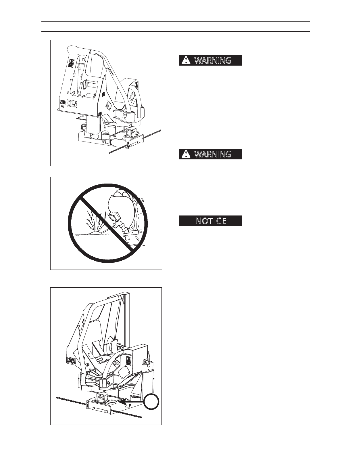
SCHEDULED AND PERIODIC MAINTENANCE SERVICES
WARNING
WARNING
NOTICE
DAILY OR EVERY 10 HOURS
PERFORM A DAILY VISUAL INSPECTION
Failure to perform a daily inspection of machine
can result in machine damage and severe personal
injury or death.
In addition to the required daily inspection outlined in
Pre-Start Inspection section perform a daily inspection
of the following components:
• Structures • Load-bearing items
• Hoses • All mountings
• Cradle Rollers • Saw bar and chain
2.05
can cause structural failure and/or severe
personal injury or death. DO NOT weld on any
structural member. Any unauthorized welding
or repair will void the warranty.
Unauthorized welding
G020.05
Immediately report any structural problems (cracks)
to an authorized dealer for diagnosis and repair or
replacement.
Unauthorized welding can
cause damage to the electrical system.
8. CHECK OIL LEVEL FOR TOPPING SAW
OILER
The topping saw oil tank ller cap is located on the left
side of the delimber toward the top, under topping
saw access cover (B).
Tank capacity is 8.4 gallons (31.75 L).
The topping saw oiler system must be bled of air any
time the system runs dry. To bleed the system, see
page 4-8 of this manual.
CTR426
B
G.151.05
713
1008
Page 70
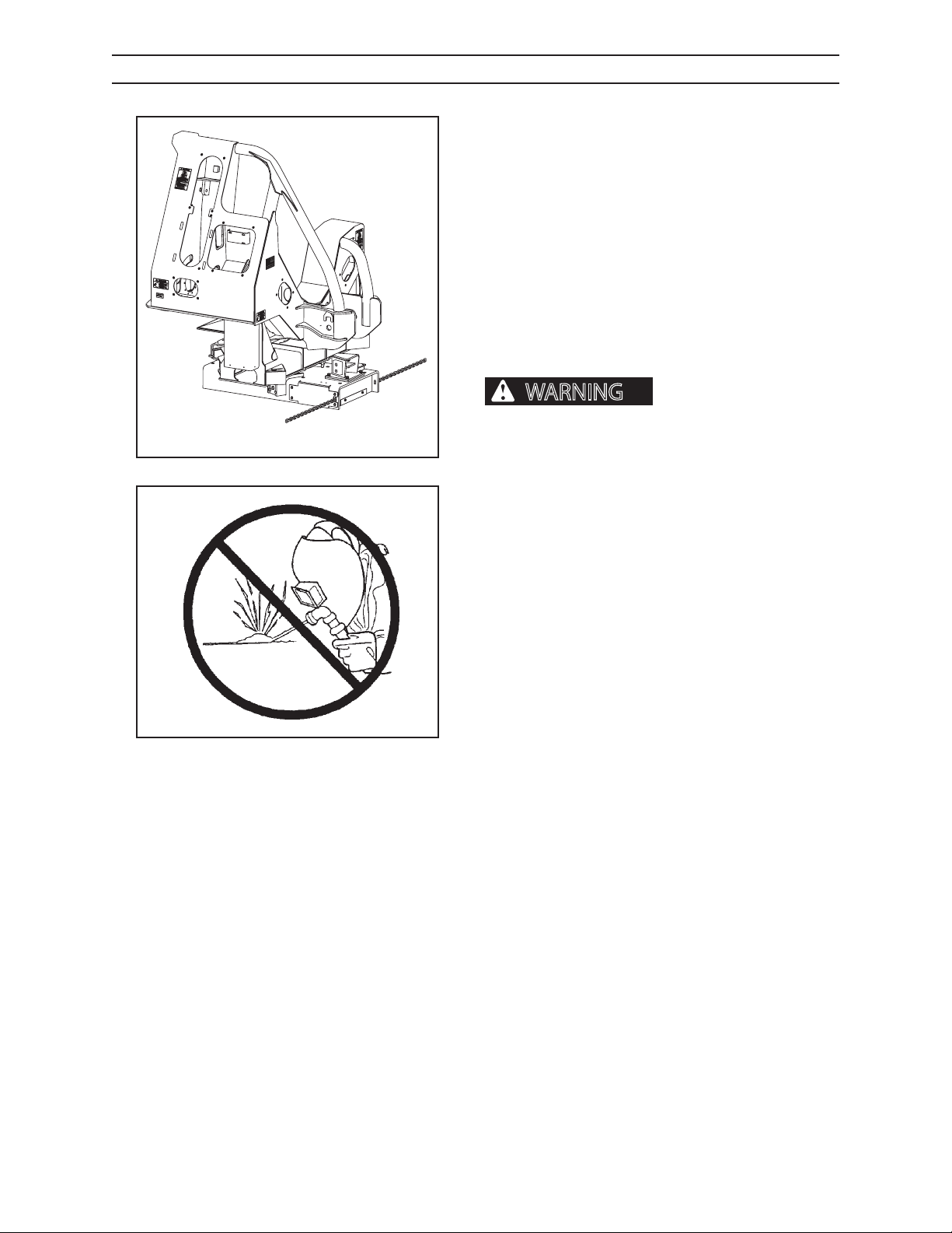
SCHEDULED AND PERIODIC MAINTENANCE SERVICES
WARNING
WEEKLY OR EVERY 50 HOURS
PERFORM A WEEKLY INSPECTION
INSPECTION GUIDELINES
1. Clean structure thoroughly. Remove all dirt, mud,
grease, oil, debris, and snow.
2. Look for rust lines in paint and missing or cracked
paint. These are indications of crack sites.
3. Inspect all welds.
4. Check all cylinders and pin keeper retainers for
broken fasteners. If broken or damaged, replace
with new fasteners.
can cause structural failure and/or severe personal
injury or death. Immediately report structural
problems (cracks) to your authorized dealer for
2.05
diagnosis and repair or replacement.
Unauthorized welding
G020.05
DO NOT weld on any structural member. Any unauthorized welding or repair will void your warranty.
Once authorized, turn battery disconnect switch OFF
and place welding ground (stinger) as close to the
weld site as possible. Do not allow weld current to pass
through bearings or pivot points.
6. Inspect safety decals. Replace safety decals
immediately if they are damaged, missing, or
hard to read. Contact your authorized dealer for
replacement safety decals. Authorized dealers will
provide free replacement safety decals if you give
them a valid serial number for your machine.
CTR426
714
1008
Page 71
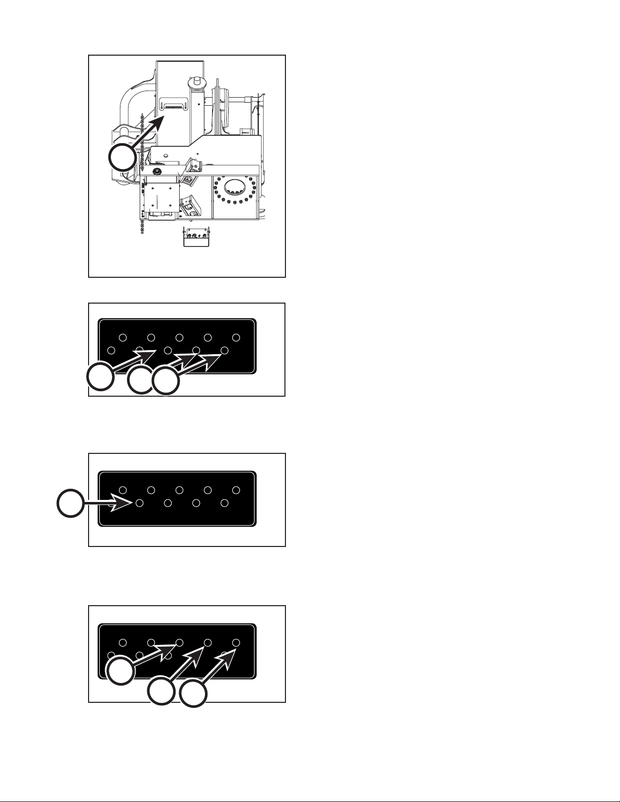
SCHEDULED AND PERIODIC MAINTENANCE SERVICES
ROTATIONAL
BEARING
SAW
BEARING
KNIFE #4
PIN ROD END
KNIFE #3
PIN ROD END
KNIFE #2
PIN ROD END
KNIFE #2
TUBE
KNIFE #3
TUBE
KNIFE #4
TUBE
SAW CYL
ROD END
CRADLE
PIVOT
10065080 12/04 Rev B 01/06
ROTATIONAL
BEARING
SAW
BEARING
KNIFE #4
PIN ROD END
KNIFE #3
PIN ROD END
KNIFE #2
PIN ROD END
KNIFE #2
TUBE
KNIFE #3
TUBE
KNIFE #4
TUBE
SAW CYL
ROD END
CRADLE
PIVOT
10065080 12/04 Rev B 01/06
ROTATIONAL
BEARING
SAW
BEARING
KNIFE #4
PIN ROD END
KNIFE #3
PIN ROD END
KNIFE #2
PIN ROD END
KNIFE #2
TUBE
KNIFE #3
TUBE
KNIFE #4
TUBE
SAW CYL
ROD END
CRADLE
PIVOT
10065080 12/04 Rev B 01/06
WEEKLY OR EVERY 50 HOURS
A
View from Underneath Delimber
LUBRICATE DELIMBER
Lubricate delimber using the Lubrication Bank (A).
G13804
9. LUBRICATE KNIFE ARM TUBES
Lubricate knife arm tubes (B, C & D) with Premium
Moly-Lith #2 grease until grease is forced out.
B
C
D
10065080
10. LUBRICATE TOPPING SAW CYLINDER
Lubricate topping saw cylinder (E) with Premium MolyLith #2 grease until grease is forced out.
E
10065080
11. LUBRICATE KNIFE ARM CYLINDER
Lubricate knife arm cylinder (F, G & H) with Premium
Moly-Lith #2 grease until grease is forced out.
G
CTR426
H
F
10065080
715
1008
Page 72
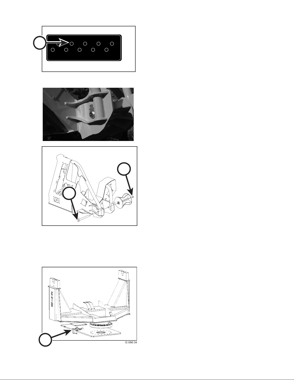
ROTATIONAL
BEARING
SAW
BEARING
KNIFE #4
PIN ROD END
KNIFE #3
PIN ROD END
KNIFE #2
PIN ROD END
KNIFE #2
TUBE
KNIFE #3
TUBE
KNIFE #4
TUBE
SAW CYL
ROD END
CRADLE
PIVOT
10065080 12/04 Rev B 01/06
A
SCHEDULED AND PERIODIC MAINTENANCE SERVICES
WEEKLY OR EVERY 50 HOURS
12. LUBRICATE SAW BEARING
Lubricate saw bearing (A) with Premium Moly-Lith #2
grease until grease is forced out.
10065080
13. LUBRICATE FEED ROLLER SHAFTS
B
Lubricate feed roller shafts (B & C) with Premium MolyLith #2 grease until grease is forced out.
C
10082284.05
14. LUBRICATE CRADLE ROLLERS
Lubricate cradle rollers (D) with Premium Moly-Lith #2
grease until grease is forced out.
CTR426
D
716
1008
Page 73
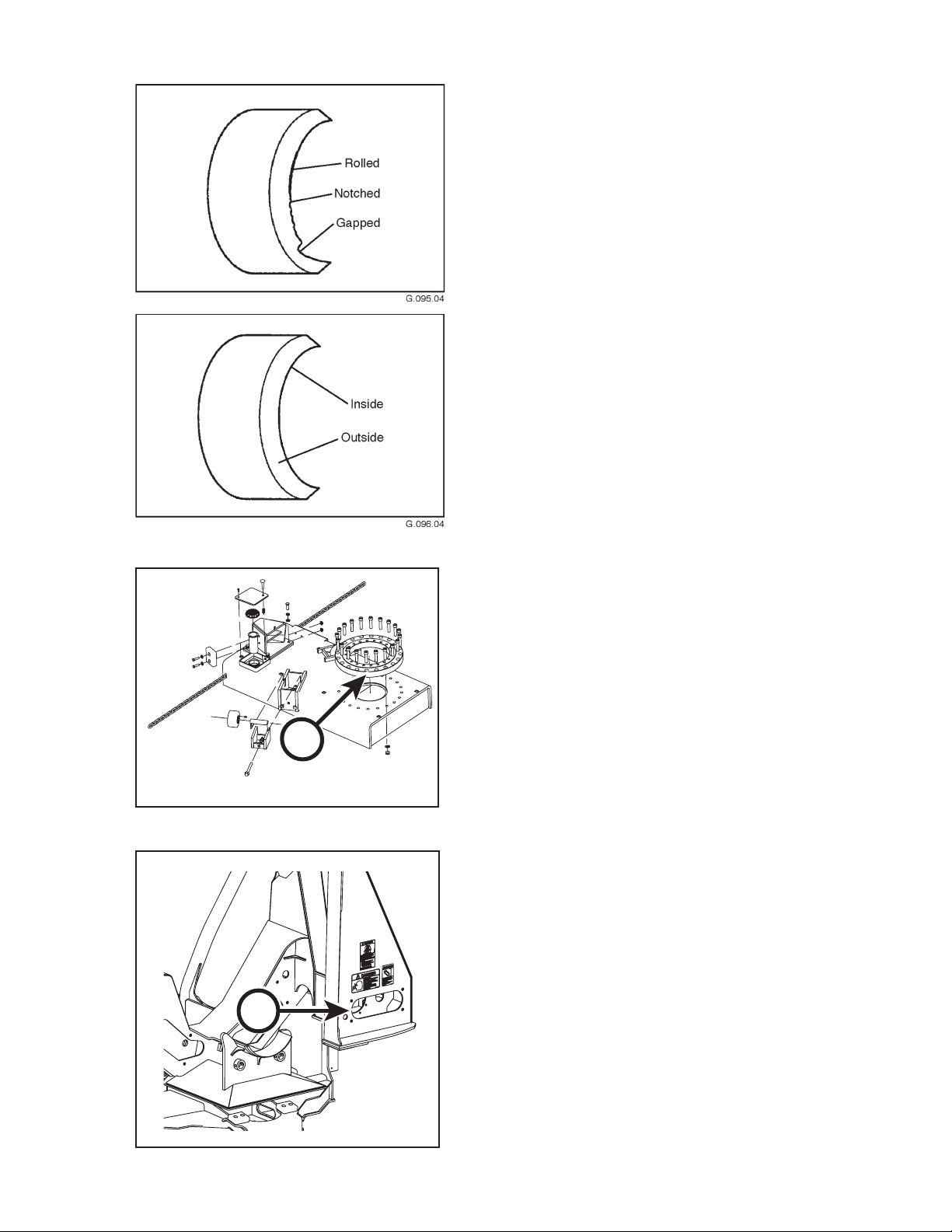
SCHEDULED AND PERIODIC MAINTENANCE SERVICES
WEEKLY OR EVERY 50 HOURS
15. INSPECT KNIFE ARM BLADES
Inspect knife arm blades for gapped, rolled, or notched
edges. Small knicks, gaps and rolls can be easily removed with an 8 or 10-inch at mill bastard le.
Touch up blades as is done for an ax or bladed cutting
tool. Blades should need ling once a month. Blades
are made of alloy steel that tends to self-sharpen, causing edges to wear thing. This may cause blade edges
to roll, dulling the blades.
C
16. LUBRICATE LARGE ROTATION
BEARING
Lubricate large rotation bearing (B) weekly with Premium Moly-Lith #2 grease, 3-5 shots. If delimber is used
intermittently or infrequently, less frequent lubrication
intervals are appropriate.
B
10081430.04
17. LUBRICATE SAW BAR BEARING
Lubricate saw bar bearing (C) weekly with Premium
Moly-Lith #2 grease until grease is forced out. If delimber is used intermittently or infrequently, less frequent
lubrication intervals are appropriate.
CTR426
G14304
717
1008
Page 74
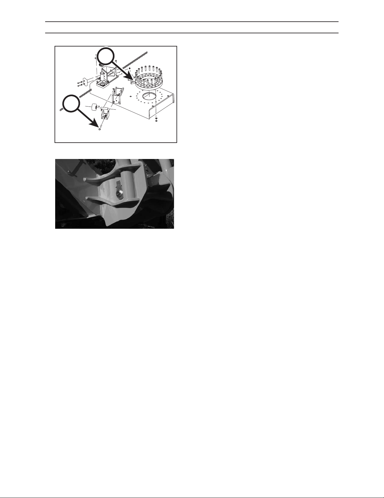
SCHEDULED AND PERIODIC MAINTENANCE SERVICES
MONTHLY OR EVERY 250 HOURS
A
A
18. ADJUST CRADLE ROLLERS
Adjust cradle rollers using the support roller adjustment bolts (A) located beneath the roller mounting
brackets. Adjust the roller to make contact only. Turn
bolt clockwise to raise roller, clockwise to lower roller.
10081430.04
CTR426
718
1008
Page 75
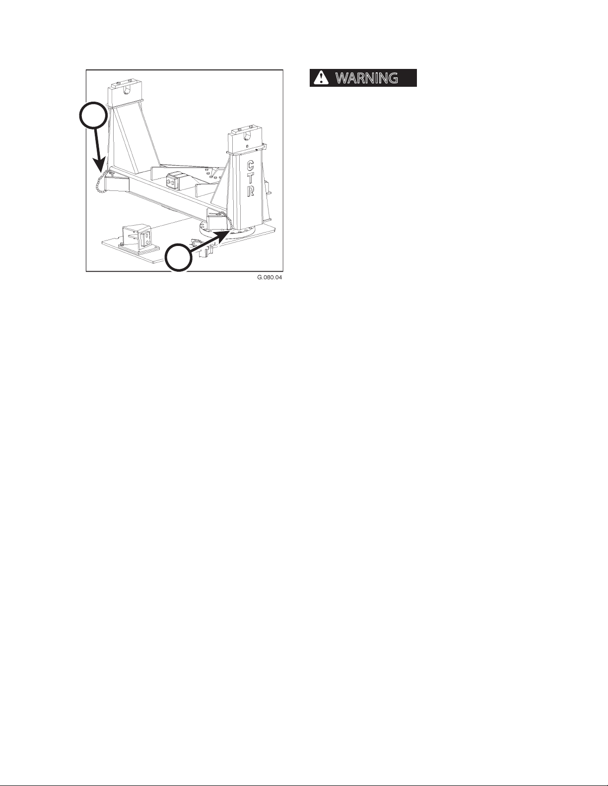
WARNING
A
TRANSPORTING
Failure to follow these important safety rules could result in serious personal
injury or death.
• Remove any obstacles from trailer oor.
• Always use a ramp of proper height, loading angle
and strength.
• Load and unload trailer on level ground.
• Properly chain load to trailer bed.
• During transport, observe height clearance of
obstructions such as overhead bridges.
B
During transport, the delimber cradle is secured to the
subbase with transport securing chains. These chains
must be hooked to the cradle before transport (A and
B). If the chains are not attached, the delimber head
can rotate freely, which could cause damage to the
cradle mount and the delimber.
81
1008CTR426
Page 76

NOTES
CTR426
82
1008
Page 77

STORAGE
NOTICE
NOTICE
STORAGE
PREPARING DELIMBER FOR STORAGE
If possible, store delimber under cover and out of weather, in well-ventilated area. Block
tires to prevent accidental machine movement.
If delimber will be stored for an extended period or stored in a corrosive environment
(such as salt air or industrial pollution), using a sponge, apply Chrome Kote Corrosion Preventive to portions exposed
to air. Also apply Chrome Kote Corrosion Preventive to all wiring connections. Reapply Chrome Kote Corrosion Preventive every 3 months while delimber remains in storage.
1. Top o the hydraulic system with hydraulic uid.
2. Remove saw bar and saw chain. Submerse chain in a container of chain oil or engine oil to prevent rust.
3. Wash down saw bar with kerosene or a nonammable solvent to remove tree sap and gum. Scrape out any
material packed in saw bar groove with a piece of 0.122 thickness stock. Oil saw bar and wrap in oiled craft
paper.
4. Clean and lubricate exposed saw bars, guide arm and blade arm cylinder rods with a light lm of grease.
5. Lubricate bearings and ttings as directed in Scheduled and Periodic Maintenance Services section.
6. Store the delimber in an area away from corrosive chemicals or fumes.
CTR426
91
1008
Page 78

STORAGE
TAKING DELIMBER OUT OF STORAGE
1. Clean machine and attachments thoroughly.
2. Check all uid levels. If low, check for leaks. Add uids as required.
3. Start machine. Cycle all hydraulic functions several times.
4. Check condition of all hoses and connections.
5. Review this operator’s manual.
Chrome Kote Corrosion Preventive is compatible with hydraulic oil and seal materials. It does not have to be
removed when taking machine out of storage. When using a dierent brand of corrosion preventive, be sure to
check manufacturer’s recommendations on whether it should be removed prior to operation.
CTR426
92
1008
Page 79
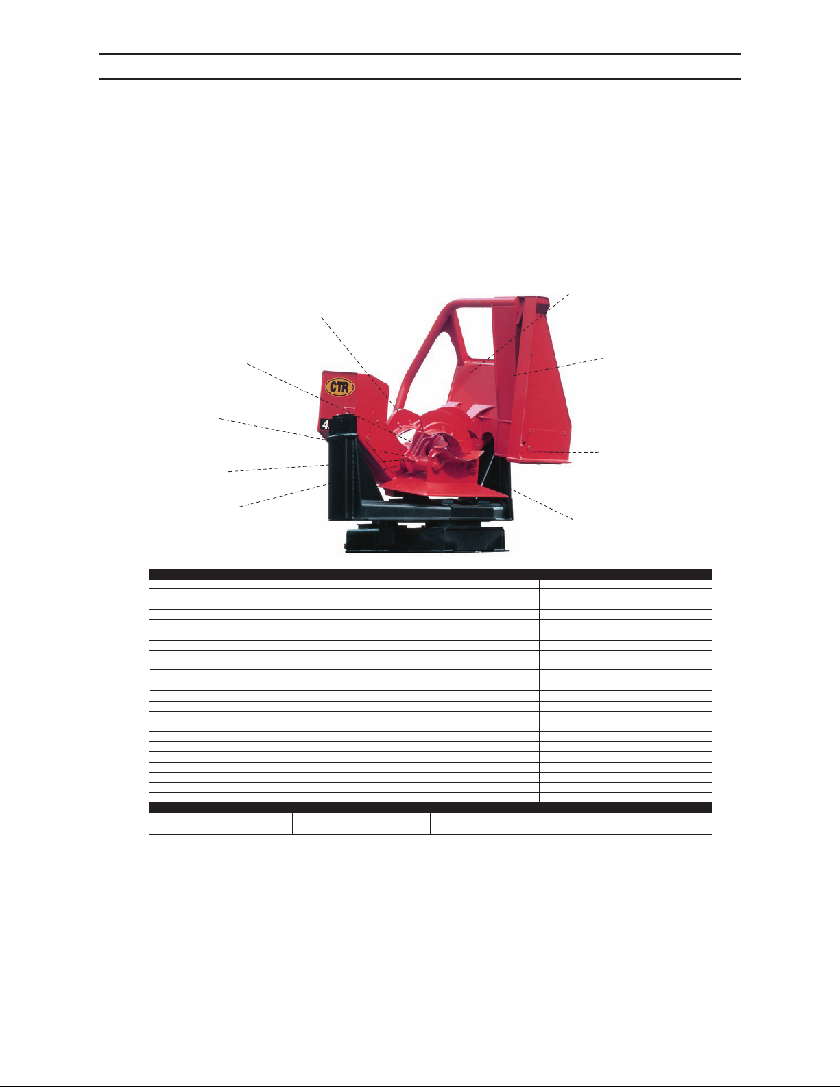
SPECIFICATIONS
C T R 4 2 6 D E L I M B E R
CTR 426 DELIMBER SPECIFICATIONS
CTR 426 DELIMBER APPLICATIONS
Small, Medium & Large Softwoods
X
Medium Hardwoods
X
smetS elpitluMsdoowdraH egraL
X
26”
(1) 21” wide x 16” diameter
NA
4
14”
Standard
55 gpm low ow; up to 90 gpm standard ow
44”
X
Optional
Auto-tension
3/4
66
Automatic, 8.25 Gallon Reser voir Capacity
Bore -- 2” with Cushions, Rod -- 1”
Direct
4” Case Hardened, 9 Teeth
22” Diameter
83”, Length, 86” Width, 99.7” Height
H-D Rotating Cradle, Pins -- 3” Diameter
7500 Lbs. with Accumulator Box
Hydraulic cushions in the
three knife blade cylinders
increases knife life.
Four knife design opens wide for
increased stem capacity and handles
tree diameters up to 24”.
Larger throat opening (26” nominal) 34 3/8”
at top and 21 1/2” at bottom for easier and
quicker loading.
5” diameter knife blade tubes pivoting
on 1 7/8” shafts for increased strength.
Centralized lubrication
allows easier maintenance
from ground level.
Improved cradle design and bearing
attachment to uniformly transfer
stress loads.
One piece tubular log guide and boxed
steel frame is more rigid for increased
strength.
Topping saw with auto
tensioner design developed
to maintain production and
minimize maintenance.
Knives sharpened on both sides
to allow pull/push delimbing and
increased production.
THE CTR 426 DELIMBER.
The new CTR 426 delimber contains design improvements and enhancements that will improve production, reliability, and
component life. The knife design with 26” throat is ideal for multiple stem softwood, large pine and medium size hardwood
applications. The 426 delimber also features a 44” topping saw with Auto-tensioner System that increases production and
minimizes chain maintenance.
Throat Opening
Nose Rollers
Throat Rollers
Number Knives
Alloy Steel Blades
Hydraulic Self-tensioning Blade Feed
Required Flow from Loader
Roller Tip Saw Bar
Topping Saw Motor
Standard
Low Flow
Oregon Brand 11H Bar Chain
Pitch
Drive Links
Chain Oiler
Knife Cylinders
Saw Drive
Drive Sprocket
Rotating Bearing
Frame Dimensions
Mounting Base
T
otal Weight
SPECIFICATIONS
CTR 426 DELIMBER
CTR RESERVES THE RIGHT TO CHANGE SPECIFICATIONS WITHOUT NOTICE TO FOLLOW ITS POLICY OF
CTR426
CONSTANTLY IMPROVING PRODUCTS.
101
1008
Page 80
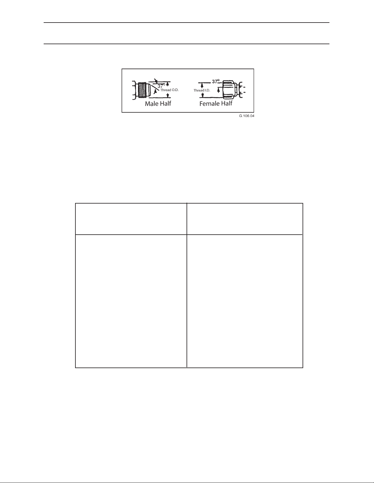
SPECIFICATIONS
HYDRAULIC CONNECTION TORQUE SPECIFICATIONS
SAE 37° FLARE CONNECTION
HOW CONNECTION WORKS:
This connection seals on two mating 37° seats.
HOW TO TIGHTEN CONNECTION:
Use a torque wrench to rotate and tighten nut. Turn nut to value shown in table below.
TORQUE
DASH SIZE THREAD SIZE INCHLBS NEWTONMETERS
-3 3/8 - 24 8-9 11-12
-4 7/16 - 20 11-12 15-16
-5 1/2 - 20 14-16 19-21
-6 9/16 - 18 18-20 25-27
-8 3/4 - 16 36-39 49-53
-10 7/8 - 14 57-63 77-84
-12 1 1/16 - 12 79-88 108-118
-14 1 3/16 - 12 83-92 113-124
-16 1 5/16 - 12 108-113 147-153
-20 1 5/8 - 12 127-133 172-180
-24 1 7/8 - 12 158-167 215-225
-32 2 1/2 - 12 245-258 332-350
The above torque values are good for:
• machined adapters and hose ttings
• ared tubed (with sleeve and nut)
• universal radius ared tubes
CTR RESERVES THE RIGHT TO CHANGE SPECIFICATIONS WITHOUT NOTICE TO FOLLOW ITS POLICY OF
CONSTANTLY IMPROVING PRODUCTS.
CTR426
102
1008
Page 81
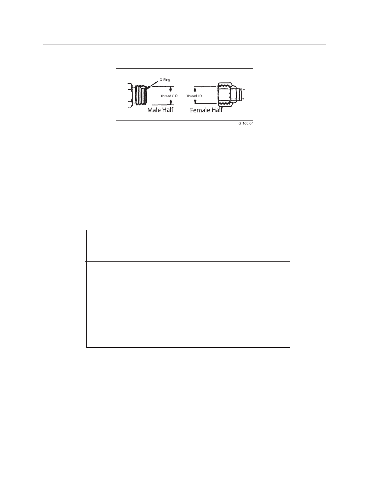
SPECIFICATIONS
HYDRAULIC CONNECTION TORQUE SPECIFICATION
ORING FACE SEAL CONNECTION
HOW CONNECTION WORKS
This connection seals with an o-ring on the male against a at surface.
HOW TO TIGHTEN CONNECTION
Use a torque wrench to rotate and tighten nut. Turn nut to value shown in table below.
TORQUE
DASH SIZE THREAD SIZE INCHLBS NEWTONMETERS
-4 9/16 - 18 19 26
-6 11/16 - 16 31 42
-8 13/16 - 16 46 62
-10 1-14 71 96
-12 1 3/16 - 12 91 123
-16 1 7/16 - 12 130 176
-20 1 11/16 - 12 171 232
-24 2 -12 210 285
Make sure the o-ring does not fall out of the male end before connection is made.
Proper lubrication helps.
CTR RESERVES THE RIGHT TO CHANGE SPECIFICATIONS WITHOUT NOTICE TO FOLLOW ITS POLICY OF
CONSTANTLY IMPROVING PRODUCTS.
CTR426
103
1008
Page 82
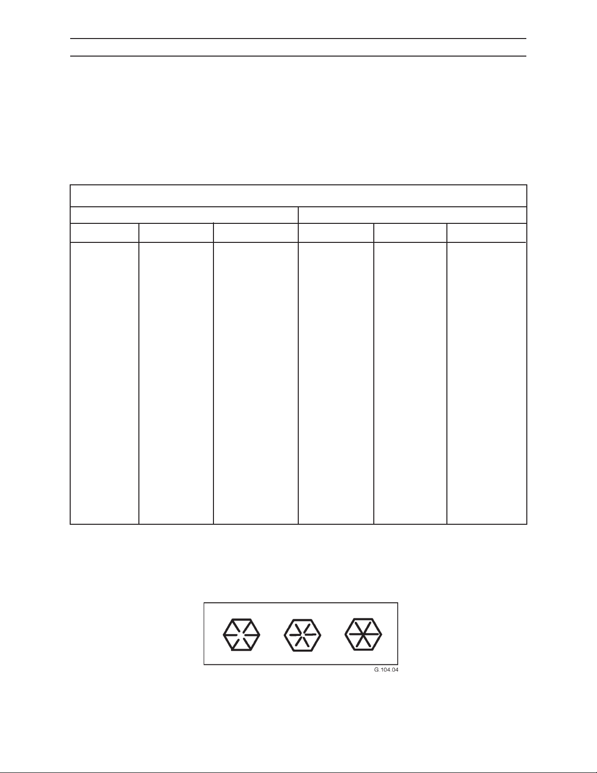
SPECIFICATIONS
TORQUE CHART FOR FASTENERS
This torque chart applies to lubricated threads for bolts, capscrews, and studs.
These specications do not apply to self-locking nuts or capscrews. To obtain proper torque, do not use lock
washers. Hardened at washers are recommended.
GRADE 8 FASTENERS
COARSE THREAD FINE THREAD
Nominal Size Torque (ft-lbs) Torque (N•m) Nominal Size Torque (ft-lbs) Torque (N•m)
1/4 - 20 8-9 11-12
5/16 - 18 17-19 23-26
3/8 - 16 33-36 45-49
7/16 - 14 52-57 71-77
1/2 - 13 76-84 103-114
9/16 - 12 105-115 142-156
5/8 - 11 162-178 220-241
3/4 - 10 266-294 361-399
7/8 - 9 437-483 593-655
1 - 8 646-714 876-968
1 1/8 - 7 912-1008 1237-1367
1 1/4 - 7 1292-1428 1752-1936
1 1/2 - 6 2242-2478 3040-3360
1 3/4 - 5 3048-3688 4133-5001
2 - 4 1/2 4610-5096 6251-6910
1/4 - 28 9-10 12-14
5/16 - 24 19-21 26-28
3/8 - 24 35-37 46-50
7/16 - 20 53-58 72-79
1/2 - 20 86-94 117-128
9/16 - 18 124-136 168-184
5/8 - 18 171-189 232-256
3/4 - 16 304-336 412-456
7/8 - 14 475-525 644-712
1 - 12 703-777 953-1054
1 1/8 - 12 979-1081 1328-1466
1 1/4 - 12 1425-1575 1932-2136
1 1/2 - 12 2527-2793 3427-3787
1 3/4 - 12 4004-4424 5429-5999
2-12 6116-6760 8293-9167
Use these torque values unless otherwise specied. Exceptions are noted where applicable. SAE Grade 8 fasteners (A.S.T.M. A354, Grade BD) are made from quenched and tempered medium carbon steel. Grade 8 fasteners
have 6 equally spaced radial lines embossed on the head of the fastener (see illustration below).
CTR RESERVES THE RIGHT TO CHANGE SPECIFICATIONS WITHOUT NOTICE TO FOLLOW ITS POLICY OF
CONSTANTLY IMPROVING PRODUCTS.
CTR426
104
1008
Page 83
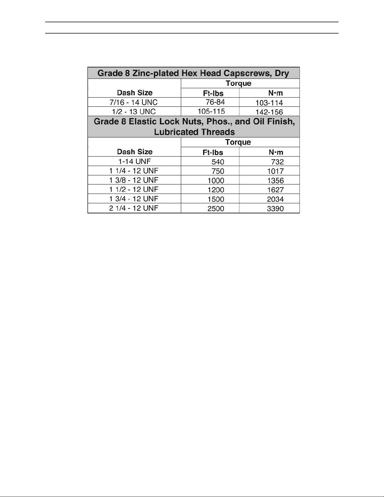
SPECIFICATIONS
CYLINDER TORQUE SPECIFICATIONS
G.103.04
CTR RESERVES THE RIGHT TO CHANGE SPECIFICATIONS WITHOUT NOTICE TO FOLLOW ITS POLICY OF
CONSTANTLY IMPROVING PRODUCTS.
CTR426
105
1008
Page 84

SPECIFICATIONS
NOTES
CTR RESERVES THE RIGHT TO CHANGE SPECIFICATIONS WITHOUT NOTICE TO FOLLOW ITS POLICY OF
CONSTANTLY IMPROVING PRODUCTS.
CTR426
106
1008
Page 85
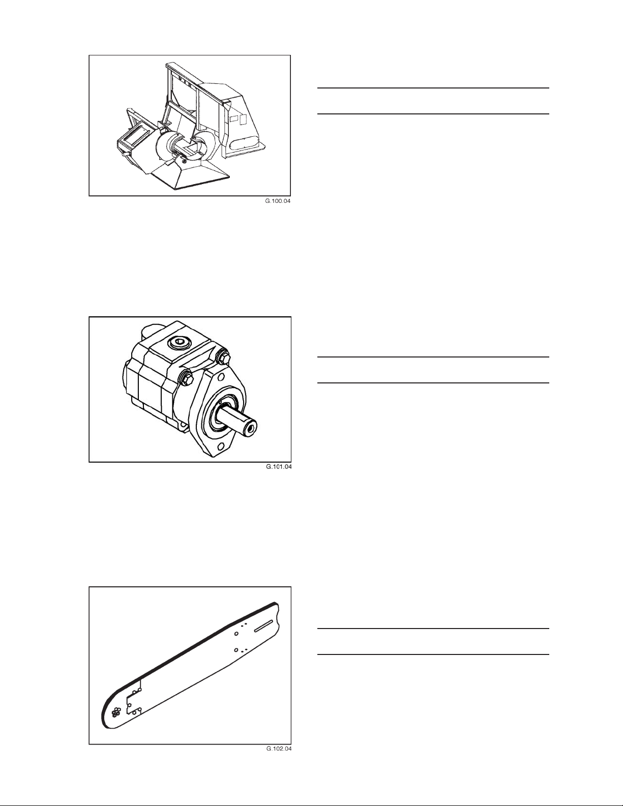
SERIAL NUMBERS
SERIAL NUMBERS
Delimber model and serial number
Topping saw motor model and serial number
Saw bar and chain model and serial numbers
CTR426
111
1008
Page 86

SERIAL NUMBERS
NOTES
CTR426
112
1008
Page 87

MATERIAL SAFETY DATA SHEETS
MSDS
Federal Occupational Safety and Health Administration (OSHA) Standard 29 CFR 1910.1200, and in some cases
state and local right-to-know laws may required specic material safety data sheets (MSDS) be made available
to employees before operating this equipment. This may include information on substances contained in this
equipment such as antifreeze, brake uid, battery acid, hydraulic uid, and R-134A refrigerant (if machine is
equipped with air conditioning).
Caterpillar Forest Products will provide, free of charge, MSDS that apply to this machine. Simply request them
from an authorized dealer.
To ensure a prompt response to an MSDS request, include return address (including zip or postal code) and machine model number and serial number with request.
121
1008CTR426
Page 88

NOTES
CTR426
122
1008
Page 89

GLOSSARY
Accumulator - A device that stores uid to assure a
constant supply at working pressure in a hydraulic
system.
Bleed - To purge air from a hydraulic line or system.
Chain Pitch - The distance between any two adjacent
links in a saw chain, the measurement being half
the distance from the front rivet hole center of one
link to the front rivet hole center of the next.
Chain Tooth - A one-piece link having a depth gauge
projection ahead of the cutting edge.
Crimp Fitting - A hose coupling press-tted to the
hose by deforming the metal.
Danger Area - The area around the delimber to be
kept clear of all personnel except machine operators in cabs.
Delimb - To remove tree limbs, leaving the tree stem.
Depth Gauge - The part of a saw chain tooth that
controls the depth of the cut, also called a “stop” or
“drag.”
Drive Link - The part of the saw chain driven by the
sprocket.
Goal Post - A nickname given to the delimber stem
guide because it resembles a football goal post.
Hydraulic - Operated by water or other liquids in mo-
tion or under pressure.
Journal - The portion of a shaft or axle containing a
plain bearing.
Joystick - Originally an airplane control, now any stick-
type hand control.
Knuckleboom Loader - A loader with a exibly-joint-
ed boom.
Pedestal - A base for mounting something such as a
delimber.
Remote Control - A unit consisting of a transmitter
and receiver combination.
Slash - What remains of a tree after removal of the
marketable part.
Stem - Tree removed from its stump.
Stump - The part of a tree left in the ground after
removal of the stem.
Tie Strap - The chain link connecting the drive link to
the cutter.
Topping Saw - A saw that cuts o the tree top after
stem is delimbed.
Grapple - A device used to pick up and hold stems for
processing.
Grapple Skidder - A machine used to move logs or
slash.
131
1008CTR426
Page 90

NOTES
CTR426
132
1008
Page 91

CALIFORNIA
Proposition 65 Warning
Diesel engine exhaust and some of
its constituents are known to the
State of California to cause cancer,
birth defects, and other reproductive harm.
Battery post terminals and related
accessories contain lead and lead
components, chemicals known
to the State of California to cause
cancer and reproductive harm. Wash
hands after handling.
CAT, CATERPILLAR, their respective logos and "Caterpillar Yellow," and the POWER EDGE trade dress as well as
corporate and product identity used herein, are trademarks of Caterpillar and may not be used without permission.
2008 Caterpillar
©
All Rights Reserved
Printed in the U.S.A.
Page 92

 Loading...