

Page 1
Page 2
CONTENTS
TE CH N IC AL CH AR A CT ER IST IC S.. .. .. .. ... .. . .. .. ... .. .. .. ... .. . .. .. ... .1
BOD Y SIZE .. ..... ..... ..... ..... ..... ..... ..... ..... ..... ..... ..... ..... ..... ..... ..... ..... ..1 -2
MAI N PARTS N AME .... .. ... ..... ..... ..... ..... ..... ..... ..... ..... ..... ..... ..... ..... ..2
I N S TA LL ATI ON R E Q U I R EM EN T.. .. .. .. .. .. .. .. .. .. .. .. .. .. .. ... . . . . . 3
INSTAL LATI ON PROCE DURE S.... .... ..... .... ..... .... .. ... .... .. ... ..4- 5- 6-7 -8
OP ER ATI NG I NSTRU CT IO N.. .. .. ... .. .. ..... .. ..... .. .. ... .. .. ... .. .. ...9- 10 -11
MAI NT EN AN CE ... .. .. .. . . . ... .. .. .. . . ... .. .. .. . . . .. .. .. .. .. ... .. .. .. .. ... .. .. 12
IM PORTA NT SA FE TY INS TR UC TI ONS.. .... .. .. ..... .... .. .. ..... .... .. 14 -1 5
TRO UBLE SH OOTIN GS... ..... ..... ..... ..... ..... ..... ..... ..... ..... ..... ..... ..... ..16
TO R EP LA CE L IGH T B ULB .. .. .. . .. .. .. .. ... .. .. .. ... .. .. .. ... .. .. .. .. .. . 12
I MP O RT AN T N OT I C E. . . .. . . .. . . .. . . .. . . .. . . .. . . .. . . .. . . .. . . .. . . .. .. 13
READ AND SAVE THESE INSTRUCTIONS MANUAL
Pl ea se no te t hat t hi s pro du ct is m ar ked w it h thi s sy mbo l:
Ac co rdi ng t o Wa s te o f El ect ri cal a nd E lec tr oni c Eq uip me nt
(W EE E) di re cti ve , W EE E sh oul d be s epa ra tel y co lle ct ed an d
tr ea ted . If a t any t im e in fu tu re yo u ne ed to d is pos e of t his
pr od uct , Pl eas e do N OT di sp ose o f th i s pr od u ct w it h hou se h old
wa st e. Pl ea se se nd t his p ro duc t to W EEE c ol l ec ti n g po in ts wh er e
av ai lab le .
16
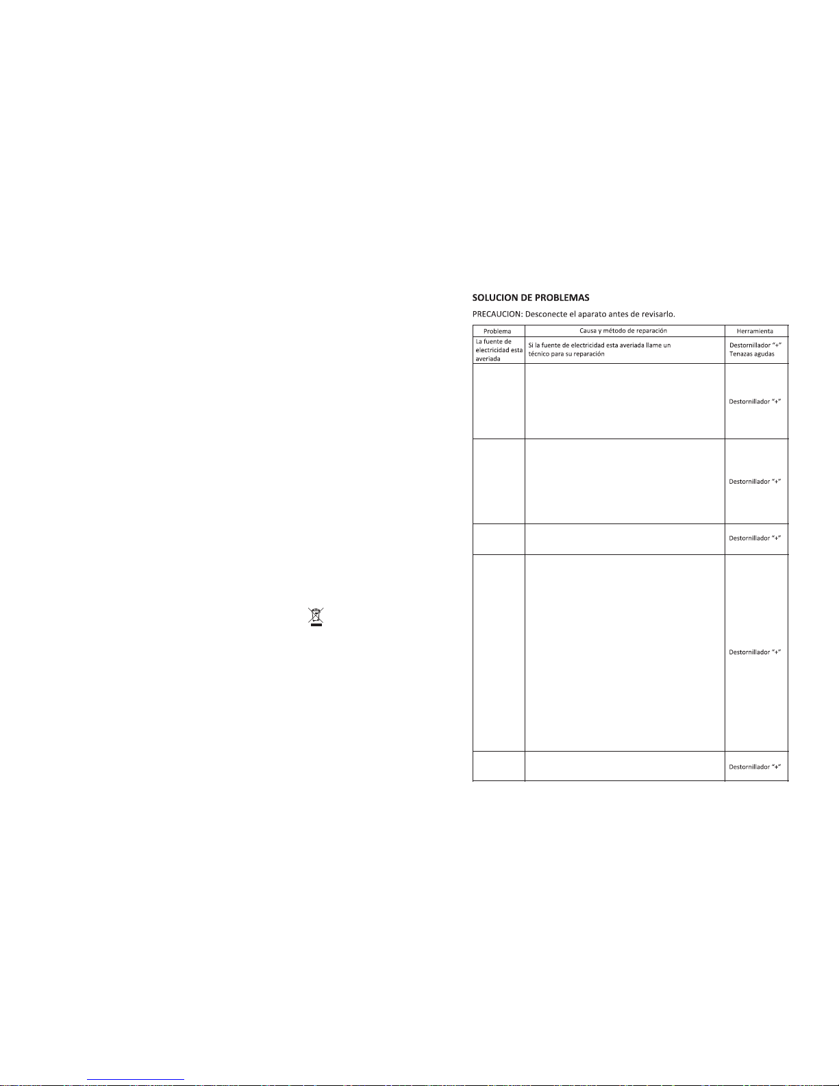
Poca
Pote ncia
de su cción
El mo tor no
arr anc a
Vib racio n
de
la un idad
Gra n rui do
Bom billo n o
fun ciona
a) El m otor no f uncio na, ree mpl ace con u n nue vo
mot or.
b) El i nterr upt or de c ont rol no fun ciona ,reem place
con u n nuevo i nterru pto r.
c) La c apaci tanci a no fu ncion a, reem pla ce una
nue va capa cit anc ia.
a) La i nstal aci ón no está s ufici entem ente firme .
Rev ise y e ste segu ro que es tá firme lo su ficie nte .
b) El v entil ado r no func iona, e ntonc es no e sta
bal ancea do. Ree mpl ace un nu evo motor.
c) El m otor no e stá firm e. Reví selo e in stálel o
suf icien tement e firme .
a)Si a lguna s parti culas c aen den tro d el
b)so plado r. Revi se y límp ielo.
a) La d istan cia d esde la c amp ana has ta la c oci na
es mu y grand e. Es te se gur o que l a distan cia sea d e
650 -700m m.
b) Ha y muc has ven tan as o pu ertas e n la co cin a, la
con vec ció n de aire e s muy g rande. C ierre a lguna s
pue rtas o ve ntan as, par a dismi nuir la c onvecc ión
del a ire.
c) Ha y exi sten cia de po co vien to en el tu bo de
esc ape. Ha cer que l a salid a del tub o de esca pe
que de haci a abajo .
d) Di sminu ción de l a tasa de a rranqu e.Ree mplac e
un nu evo mot or o ca pacitanc ia. D ebido a q ue la
cam pana se s itúa en cima de l a ventan a, la mej or
sol ución e s poner t res cap as de a lguna e speci e de
tab la en la pa rte de atr ás de la ca mpa na para c ubr i
el hu eco de la v entana .
Ree mpl ace con u na nueva l ampar a led.
Page 3
1
Dea r consu mer,
Tha nks for y our pur chase o f our coo ker hoo d and we ho pe we can f ully
sat isfy al l of your n eeds. P lease r ead ent ire ins truct ions ca reful ly befo re
pro ceedi ng to obt ain the b est res ults of u sing th e cooke r hood.
Mod el no.: □P CH796 DR □PCH7 94DR □PC H760R □P CH762 DR
□PCH 767DR □P CH797 DR
Tota l pow er: □190 W □15 4W
Thr ee spee d motor : □150W
LED l ights : □2×2W Norm al li ghts: □2×2 5W
Volta ge: 11 0~120 V Fre que ncy: 60 HZ
Fil ter: □6- layer f ilter
Con trol: □3 speed □3sp eed Pus h butto n
□PCH 990R □PC H960R □P CH896 IR
□158 W
Hig hly-s ensit ive tou ch vide o switc h
TECHN IC AL CH ARACT ER IS TI CS
BODY SI ZE
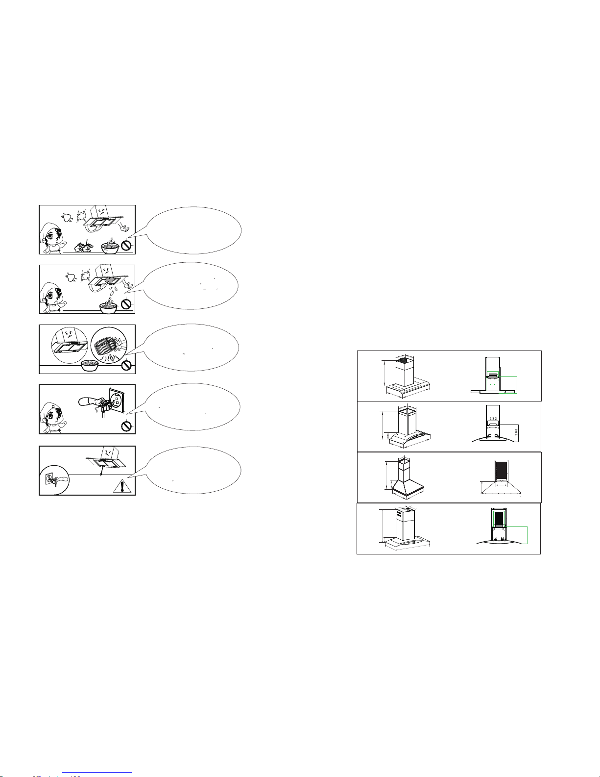
PCH 760R 63 160不带 方 边15 0风 机
597
487
189
530-920
186
213
200
180
A
B
PCH76 2DR 66 8S (6 0) /GS 14
295
285
509-900
59
475
595
PCH 794DR
30
0
283
895
480
500-880
PCH 767DR 6 88(60 )/GS1 4
15
Glo ve
Use un gu ante de p rotec cion
autes d e empez ar a limp iar la
campa na. Rem ueva lo s
compo nente s suave mente
duran te la lim pieza .
Nunca l ave el in terru ptor de
contr ol con ag ua u otro l iquid o
para ev itar qu e el liqu ido
pueda c ausar u n dano el ectri co
en el apa rato.
La limp ieza de l venti lador
del mot or debe s er hech a
por una p erson a calif icada .
Ponga m ucha at encio n para
evita r danos e n el vent ilado r
duran te su lim pieza .
Nun ca desc onect e el cabl e de
cor rient e con su ma no
hum eda par a evita r el ries go
de un a desca rga ele ctric a.
Desco necte l a campa na
extra ctora d e la fuen te de
elect ricid ad si el ap arato n o
se va a usa r por un la rgo
perio do de tie mpo.
595
480
48
483-873
283
300
A
B
232
339
341
232
A
B
A
B
Page 4
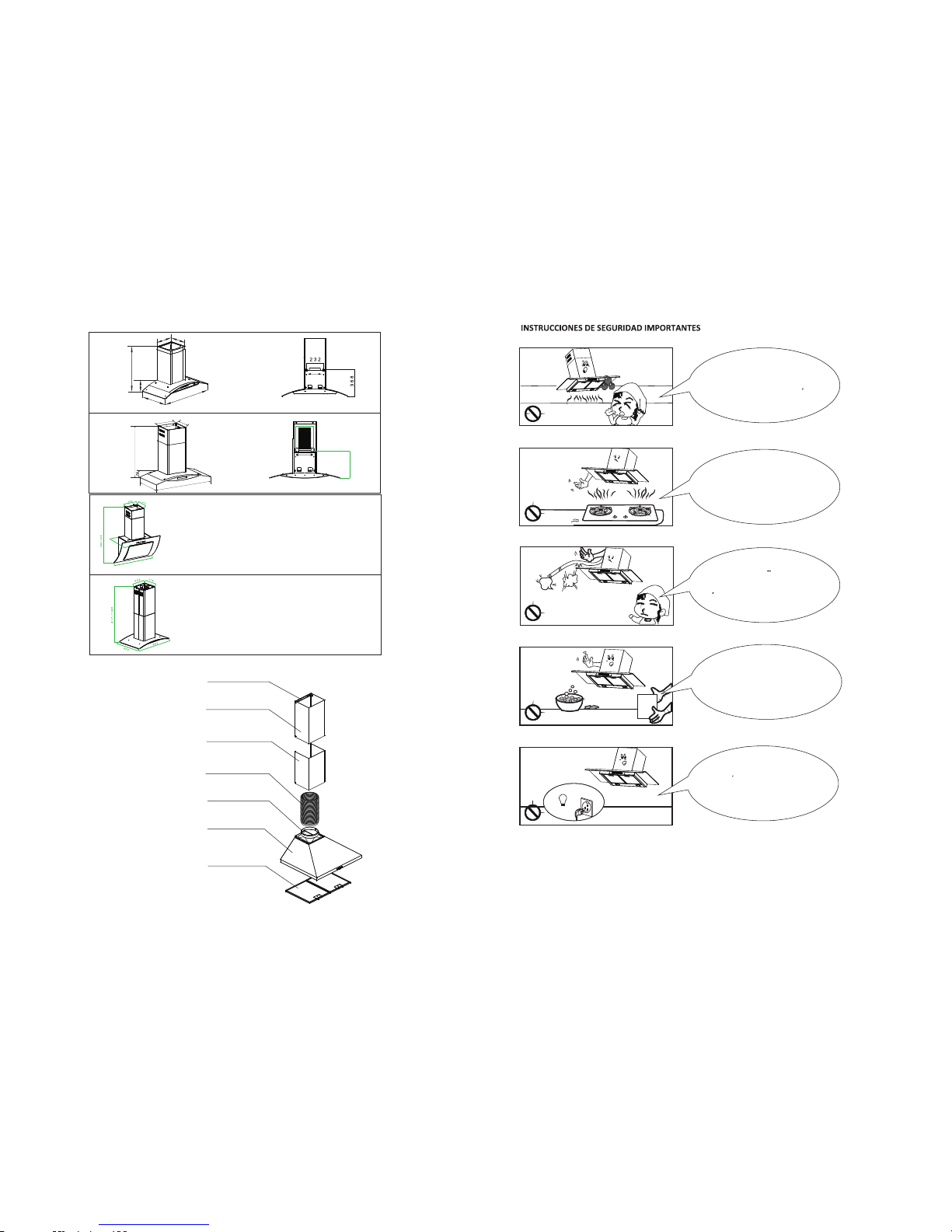
PCH 797DR 6 88/GS 14
895
480
500-880
300
283
341
232
A
B
A
B
PCH 796DR
300
283
525-920
115
475
895
2
MAIN PARTS NAME
Inne r teles copic -duct
Oute r teles copic -duct
Alum inium f ilter
Exha ust pip e
Bott om cove r
Duc t brack et
Air ou tlet
14
Man ual
Limpie la campana de
acuerdo a las instrucciones
dadas para evitar incendios.
La bombilla debe ser reemplazada
por un tecnico calificado. Use
bombillas de vatios igualeso
menores al estipulado.
En caso de danos al cable de
corriente, solicite a un
tecnico que lo repare.
No conecte la salida de
aire a chimeneas ni
ductos de combustion
de gas
No permita que arde fuego
(llamas) bajo la campana
595/8 95
Page 5
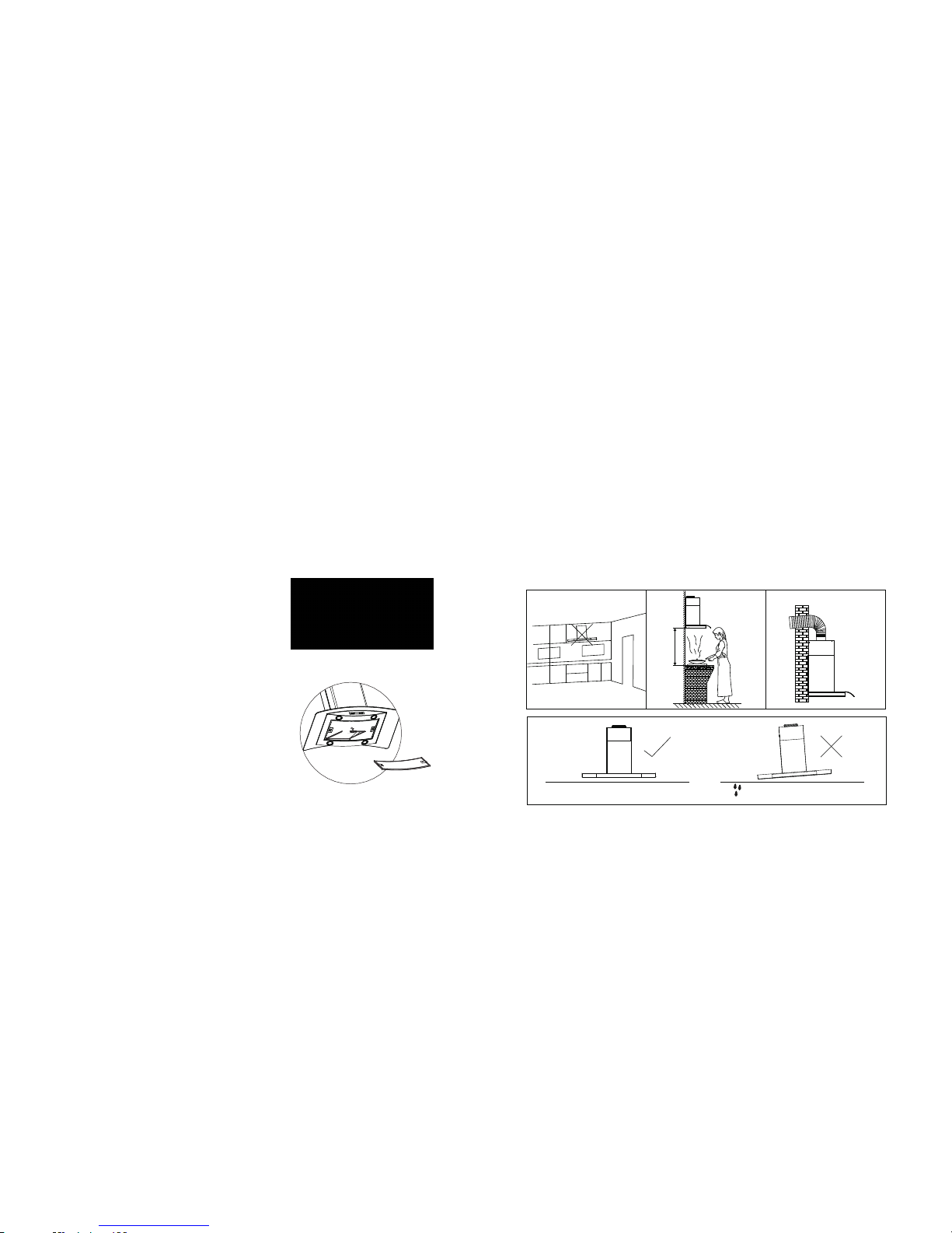
INSTAL LATION REQUIREMENT
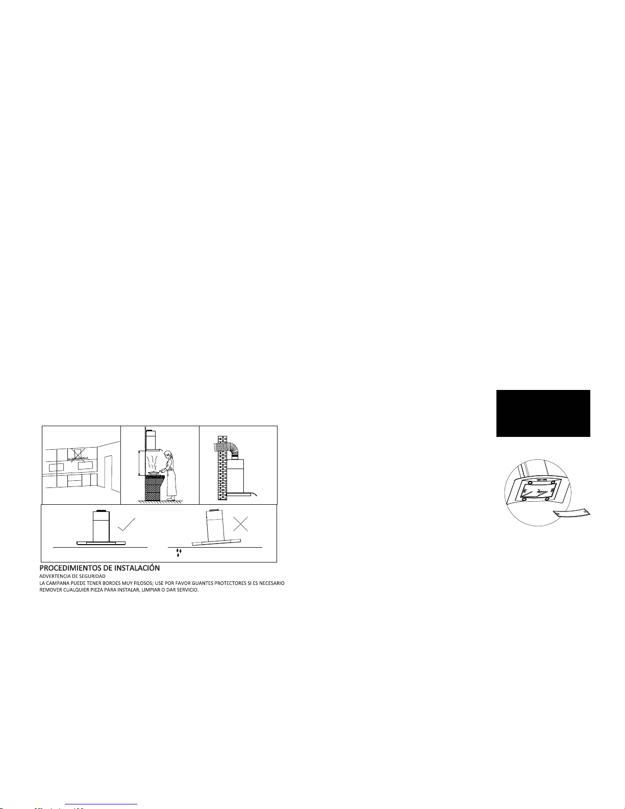
1. Do no t ins tall the co oke r hood w her e there are m any do ors or wind ows in other to av oid to
effe cti ng th e exha ust e ffic ien cy of the hoo d caused by a ir convec tio n. (F ig. 1)
2. Inst all the cooker h ood right abov e the ho b. The reco mme nde d dist ance bet ween the ho b and
the lo wer edge of the co oker hood P CH 760R,P CH7 62D R,P CH7 67D R,PCH79 7DR,PC H79 4DR
PCH 79 6DR and PCH 896I R is min imu m 650 mm and m axi mum 700mm . (Fi g. 2)
The recomme ned d ist anc e bet wee n the h ob an d the lower edge of the c ook er ho od
of PCH 990R and PC H 960 R is minim um 350mm and maximum 400mm.(F ig. 2)
3. In ord er to get the o ptimum pe rfo rma nce , do not e lon gate the ex hau st pip e too long, and tr y
to mak e the b end of exha ust p ipe le ss an d biggest , ens ure the con nec tio n is air pro of. (Fi g. 3)
4. Aft er hang ing the u nit on th e wall, e nsure t he hood i s level a nd vert ical. (Fig. 4 )
5. Th e air out le t mus t no t be co nnect ed to chi mney fl ues or co mbust ion gas
duc ts. The a ir outl et m ust u nd er no c ircum stanc es be con necte d to vent i-
lat ion duc ts for ro om in whi ch fuel -burn ing app lianc es are in stall ed.
LEVEL
Fig .4
LEAN
650~7 00mm/
350-4 00mm
Fig .1 Fig .2 Fig .3
INSTAL LATION PROCEDURES
SAF ETY WAR NIN G
HOO D MAY HAVE VERY SHAR P EDG ES; PLE ASE WEA R
PRO TECTI VE GLOV ES IF IT IS N ECESS ARY TO RE MO VE ANY
PARTS FO R INSTAL LIN G, CLEA NING OR S ERVICI NG.
6.The c oo ke r hood can be i ns ta lled eith er i n Re -circul at io n mode or Duc ti ng
mode. Al l th e mo dels al re ad y in stall c ha rc oa l filte rs i n re -c ircul at io n mo de.
If you wa nt d uc ting mode , th en t ake out the c ha rc oal fitle rs .
3
13
*Fig
Es acons ej ab le l la ma r a un a pe rs on a de s er vi ci o ca li fi cada y autorizada para
limpia r pe ri ód ic am en te e l en sa mb le i nt er no ; as í se ri a una gran m ej or a pa ra
el rendimien to d e lo s pr od uc to s.
Nota: si por a lg un a razón, no usa la campana , el a ce it e pu ed e qu e se d ep os it e
la super fi ci e y fi lt ro d e la c hi me ne a y pu ed a in ic ia rs e un g ot eo p ro du ci en do
fuego en la misma.
Nota: Ante s de rea li za r el m an te ni mi en to o e l re em pl az o de l a lá mp ar a,
descon ec te l a ca mp an a de l a fu en te p ri nc ip al ( de sp eg ue e l en ch uf e de l só ca te ).
Modo duc ci ón
No neces it a in st al ar f il tr os d e ca rb ón , po se e
escape e xt er io r. Si pu ed e ub ic ar u n es ca pe
exte ri or e nt on ce s le s ug er im os q ue s el ec ci on e
este mod o pa ra un mejor rendimiento.
Cualquie ra q sea el modo que usted sel ec ci on e
sea el de recirculac ió n o el d e du cc ió n, f il tr os
de caset e ne ce si ta n se r li mp ia do s to do l os m es es ,
pero puede que varíe el patrón de uso tambié n. E n
caso de qu e un a gran cantidad de aceit e se a us ad o pa ra cocinar, igual debe ser
limpia do c ad a se ma na p or n oc he . Fi lt ro s pu ed en s er f ác il me nt e limpiados, solo
póngalos e n un a so lu ci ón d e ja bó n y ag ua c al ie nt e, l im pi án do lo s co n un c ep illo
y enjuagán do lo s co n ag ua c or ri en te d el g ri fo , lu eg o sé qu el o co n un p añ o se co .
Rearme los filtros apropiadamente, s áq ue lo s y co ló qu el os m ed ia nt es
instru cc io ne s, p re si on an do e l se gu ro d el f il tr o ha ci a at rá s pa ra l ib er ar e l fi lt ro
de la ranura.
Nota Imp or ta nt e
A
Modo de re ci rc ul ación
Cheque e qu e el f il tr o de c ar bó n ac ti va do e st én a ju st ad os a pr op ia da me nt e, a sí
las impureza s pu ed en s er e fe ct ivamente abs or bi da s.
La campana funcionara mejor a la velocidad de segundo o más baja a modo de
tener ti em po s uf ic ie nt e pa ra l a fi lt ración del aire. Los f il tr os d e ca rb ón n o
pueden s er r eu ti li za do s, n ec es it an s er c am bi ad os p er iódicamente. La vida útil
de los fil tr os d e ca rb ón s on a pr ox im ad am en te 3 a 4 m es es . Si n em ba rg o, s i la
campana es u sa da p or m ás d e 4 ho ras en un día y se usa u na g ran cantidad de
acei te m ie nt ras cocina pue de q ue e l fi lt ro d e ca rb ón
requiera cambios más frecuentes.
El fil tro de c ar bó n ti en e qu e se r ca mb ia do
tan pronto sea sat urado. Ellos pueden ser
fácilm en te r ee mp la za do s, g ir án do lo s en
sentid o an ti h orario para sacarlos y hora ri o
para colocarlos.
Nota: El uso d e fi lt ro s de c ar bó n op ci on al o m od o du cc io n se d ej a al i ns ta la do r.
Page 6
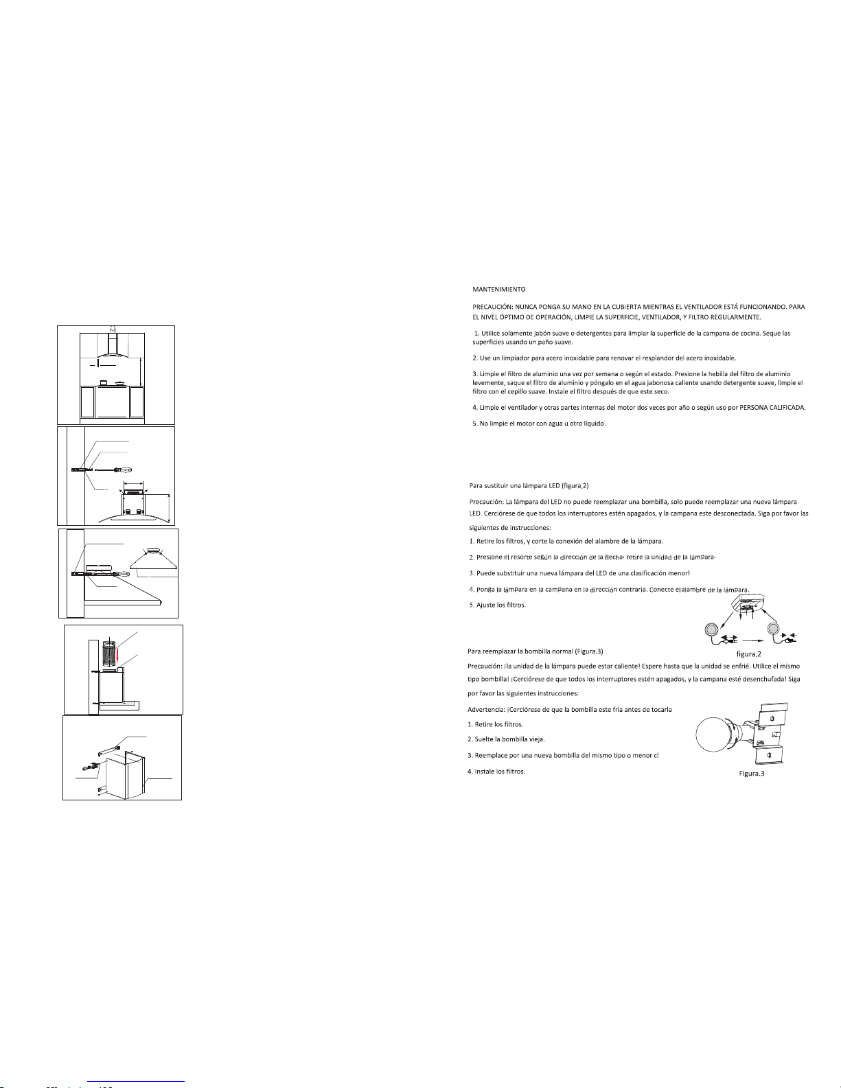
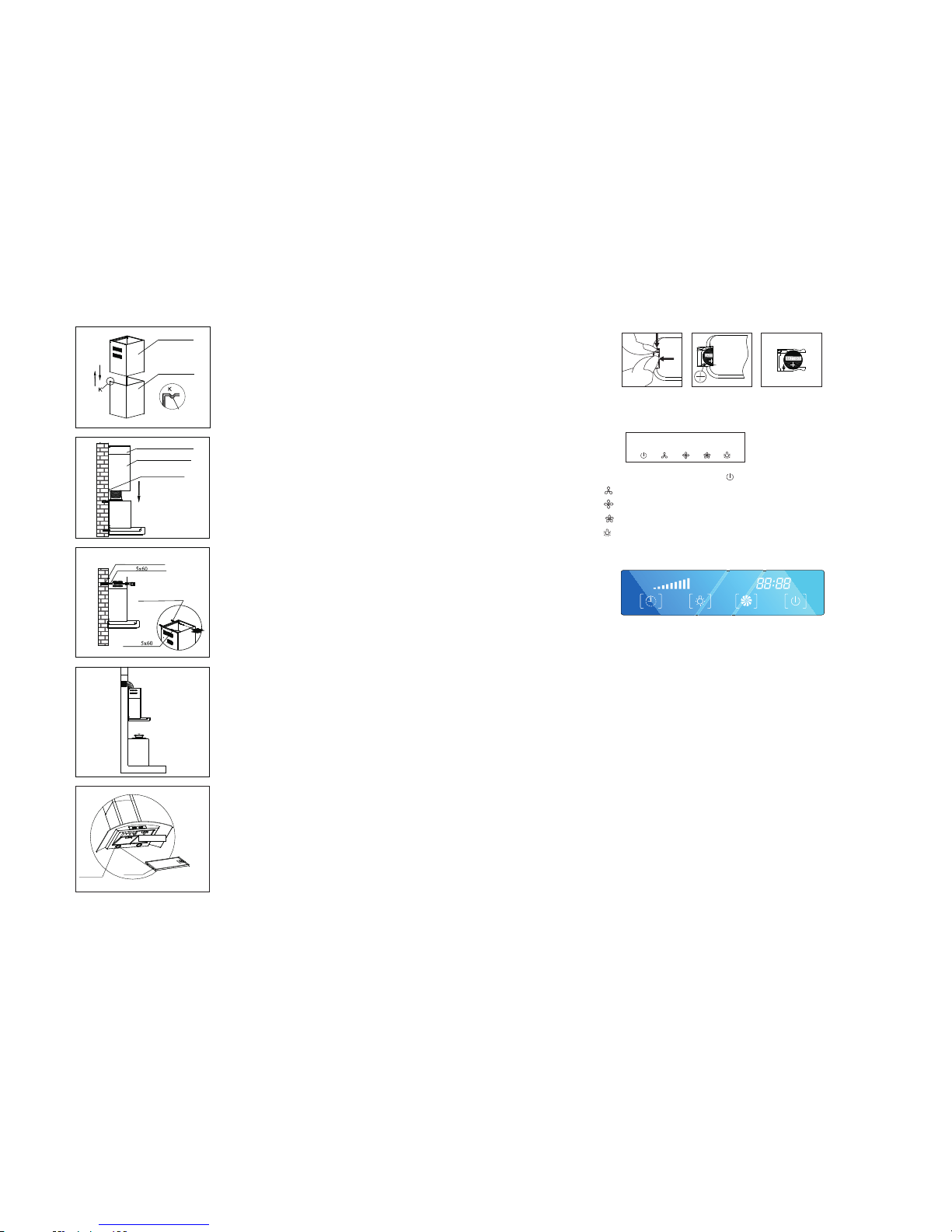
INS TALLATI ON FO R MODEL PC H7 60R,P CH 762DR ,P CH794 DR ,PCH7 96 DR,
PCH 767DR ,PCH7 97DR
Wood Sc rew
5x60
Expa nding Tu be
Hook
232mm
diffe rent
B
A
Step 2:
Accor di ng t he space be tw ee n the hole
A&B,d ri ll 2 h oles in lev el o n th e wall with
8mm in di am et er and 60-7 0m m in d epth.
Press t he 2 e xp anding tu be p ro vided int o
the hol es . Tig hten the 2 wo od s cr ews of
5x60m m wh ic h supplie d to ge ther with t he
hood to t he e xp anding tu be .M ake sure it i s
fixed e no ug h and canno t be m ov e.Hang th e
cooke r ho od o n the 2 wood sc re ws ,make
sure it i s to b e le vel and sta bl e.
Exha ust pip e
Air ou tlet
Step 3:
Take o ut t he cooker h oo d fr om the cart on
and put i t on a h or izontal w or k ta ble gentl y.
Fix the r ed uc erpipe in to t he a ir outlet o f th e
inner d uc t, a nd then fix t he e xh aust pipe i nt o
the top o f re du cer,make sur e it i s co nnected
to the re du ce r tightly.
Step 4:
Match in g th e bracket t o th e ho les of the
inner d uc t an d fix it well w it h M4
screw s.
Step 1:
Pleas e pu t th e cooker ho od o n th e wall and
mark th e po si tion wher e yo u wa nt to insta ll .
We rec ommend th e he ig ht from the h ob t o
the low er e dg e of the hood s ho ul d be from
650mm t o 70 0m m.
10mm
650- 700mm
Brac ket
Inne r duct
M4 Scre w
A
B
Expa nding Tu be
Back o f the hoo d
5x60
Wood Scr ew
4
12
Page 7
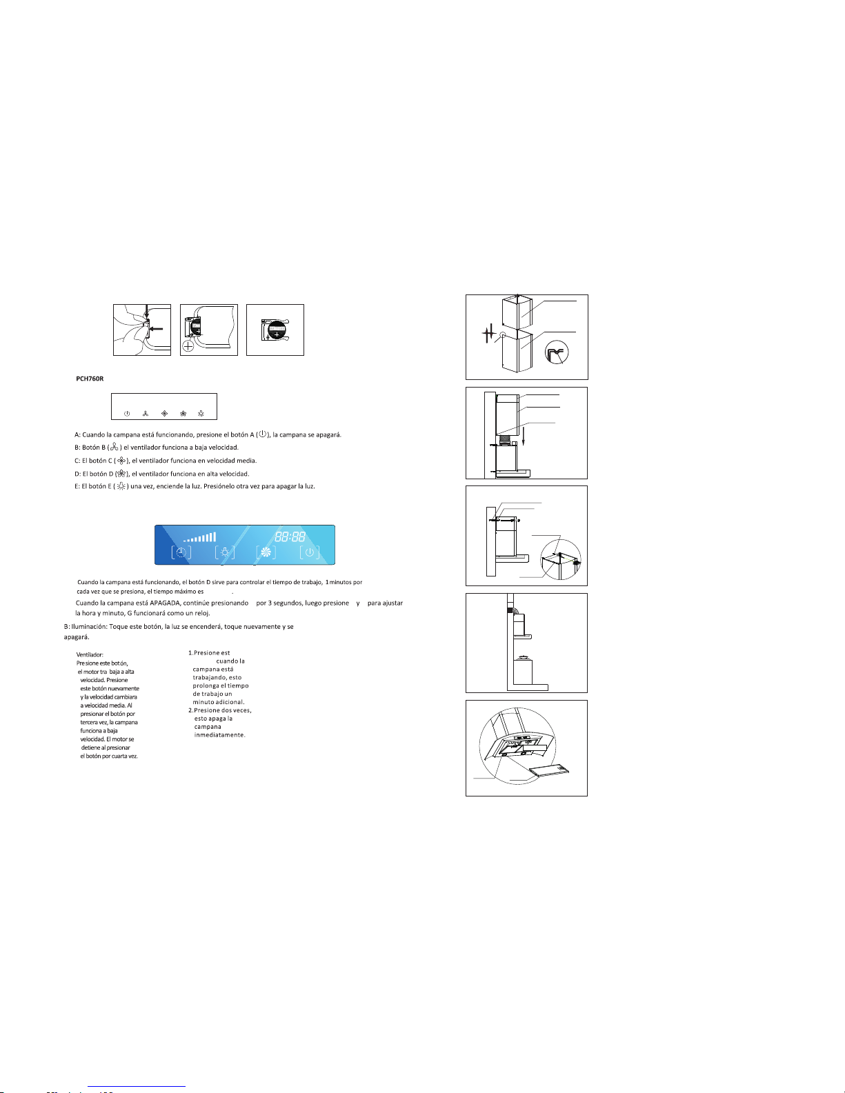
5
Step 5:
Inser t th e in ner duct in to t he o uter
duct . Pl ea se k indly not e th at t he
inner d uc t mu st fix to the o ut er d uct ’s
orien ta ti on slot.
Step 6:
Put the o ut er d uct to the un it b od y,
and use t wo M 4x 10 screws to f ix t he
outer d uc t to t he unit bod y.
Step 8:
Exten d th e ai r outlet of t he e xh aust
pipe ou t- of -door. Try to m ak e the
bend of t he e xh aust pipe i s mo re t han 120。.
Step 9:
Insta ll g re ase filte r. Ma tc h the fix p in t o
the fix h ol e an d button th e fi lt er gently a s
the dir ec ti on of arrow A.
Fix pi n
Fix ho le
A direc tion
Inne r duct
Oute r duct
K
K
Orie ntati on Slot
Inne r duct
Oute r duct
fix sc rews
5x60
Wood Scr ew
Expa nding Tu be
5x60
Wood Scr ew
Expa nding Tu be
Step 7:
1. Draw t he i nn er duct up to t he
suita bl e hi gh, mark on t he w al l two keyho le
of the ou te r du ct bracke t wi th a p en .
2. Put do wn t he i nner duct g en tl y, dri ll
the key ho le s in 60-70m m de pt h on the
horiz on ta l level usi ng 8 mm d rill.
3. Pres s th e ex panding t ub e pr ovided in to
the hol es .
4. Matc hi ng t he inner du ct w it h the holes ,
tight en t he i nner duct c ov er w ith two 5x6 0
wood sc re w pr ovided
A: Reloj
1.
PCH896I R
A
B C D
A B C D E
Pic 1 Pic 2 Pic 3
60 mi nu to s
2.
A
B
C
C:
D:
Page 8
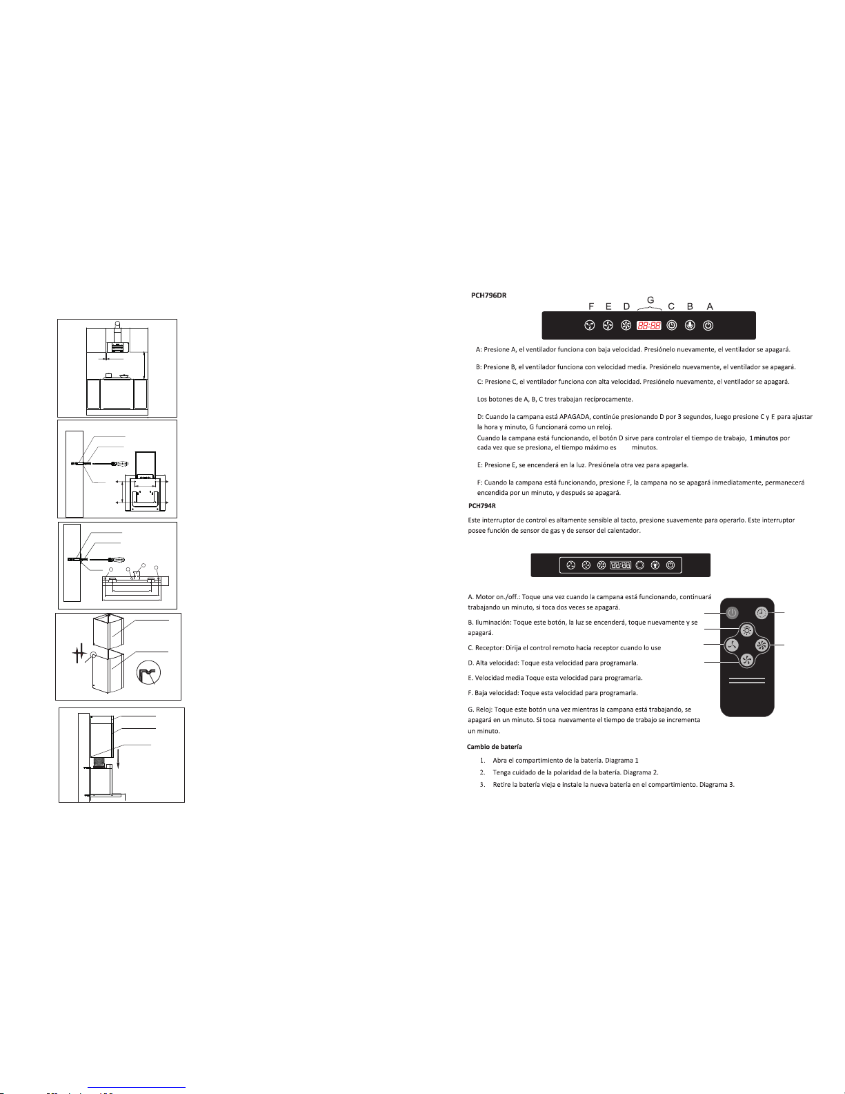
Wood Scr ew
5x60
Expa nding Tu be
Hook
A B
C
D
306
310
Step 1:
Pleas e pu t th e cooker ho od o n th e wall and
mark th e po si tion wher e yo u wa nt to insta ll .
We rec ommend th e he ig ht from the h ob t o
the low er e dg e of the hood s ho ul d be from
350mm t o 40 0m m.
10mm
350- 400mm
Insta ll at ion For Mod el P CH 990R ,P CH 9 60 R
Step 2 Fo r Mo de l PCH 990R ,P CH 9 60 R
Drill h ol es i n the wall us in g a 8 mm d rill bit. Us e
three s cr ew s to fit the ho ok o n th e wall in the s cr ew
holes 1 ,2 ,3 . Then use on e M4 X1 0 screw fit t he
appli an ce o n the screw h ol e 4 to m ake sure th e
appli an ce i s fixed and c an n ot b e moved!
3
2
165
229
250
40
Wood Scr ew
5x60
Expa nding Tu be
Hook
1
4
Inne r duct
Oute r duct
K
K
Orie ntati on Slot
Inne r duct
Oute r duct
fix sc rews
Step 3:
Inser t th e in ner duct in to t he o uter duct .
Pleas e ki nd ly note tha t th e in ner duct
must fi x to t he o uter duct ’s o ri en tation
slot.
Step 4:
Put the o ut er d uct to the un it b od y, and u se
two M4x 10 s cr ewsto fix t he o ut er duct to
the uni t bo dy.
6
10
F
A
B
E
D
G
ABCDEF
&PC H990R &PCH9 60R
59
Page 9
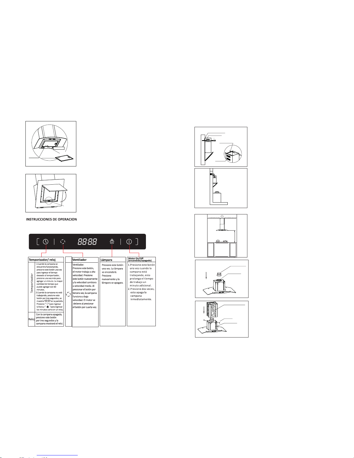
Step 6:
Exten d th e ex haust pip e to t he v ent-pip e of
your bu il di ng or to outs id e. Tr y to make the
bend of t he e xh aust pipe i s mo re t han 120°.
5x60
Wood Sc rew
Expa nding Tu be
5x60
Wood Sc rew
Expa nding Tu be
Step 5:
1.Ext en d th e inner chi mn ey t o the heigh t
which y ou w an t . And mark t he t wo h ol es of
the inn er c hi mney’s hook o n th e wa ll.
2. Put do wn t
he inne r du ct c over gent ly, u sin0- 70 m m
depth o n th e wa ll which yo u ma rk ed just now.
3. Pres s th e ex panding t ub e in to the hole s.
4.Ext en d th e inner chi mn ey a nd tighen i t to t he
expan di ng t ubes with t wo 5 x6 0 wood scre w .
g 8mm dri ll t o dr ill two hol es i n
6
7
Insta ll at ion For Mod el P CH 896I R
650- 750mm
Step 1:
Fix the p os it ion of the ch im ne y in accord an ce
with th e re co mmended h ei gh t between
650mm t o7 50 mm from the h ob a nd t he lower
edge of t he c hi mney.
Air o utlet
Red ucer fo r
φ120 o ut-le t
Low support frame
Screws
Blower box assembly
Ste p 3:
Aim ing the Low supp ort f ram e to the holes
on the blow er bo x ass emb ly , fix it tig htl y.
The n pull out th e exh aus t pipe to the l eve l
of the low su ppo rt fr ame .
Step 2:
Take o ut o f the chimn ey f ro m the carto n
box and r em ov e the filte r,t he n pu t it on a
horiz on ta l work tabl e ge nt ly. Fi x th e
reduc er t o th e airout le t if n ee ded .
Other wi se f ix the exha us t pi pe into the a ir
outle t, ma ke sure is co nn ec ted tight ly.
9
Segu ro
Pas o 9
Instale el fil tr o pi ramidal, inser ta nd o lo s
seguros en los h ue co s y em pu je s ua ve me nt e
en la dirección A para adecuarlo.
A
Direc ción
Prec aución an tes de co cinar :
Par a lo s mo de lo s PC H9 90 R& PC H960R:
Cuando coc in e, n o ne ce si ta a br ir e l pa ne l de
acero . Si usted qui er e ab ri r el p an el
cuando lim pi e el m is mo, solo ábralo como
muestra la figura s ig ui endo la dirección que
muestra la fe cha. Note que el panel no puede
cerrarse por sí solo despu és d e ab ri rl o.
vidr io
Agujero de
fijaci nó
Perno de fijaci nó
PCH 762DR Y P CH767 DR Y PCH7 97DR
Page 10
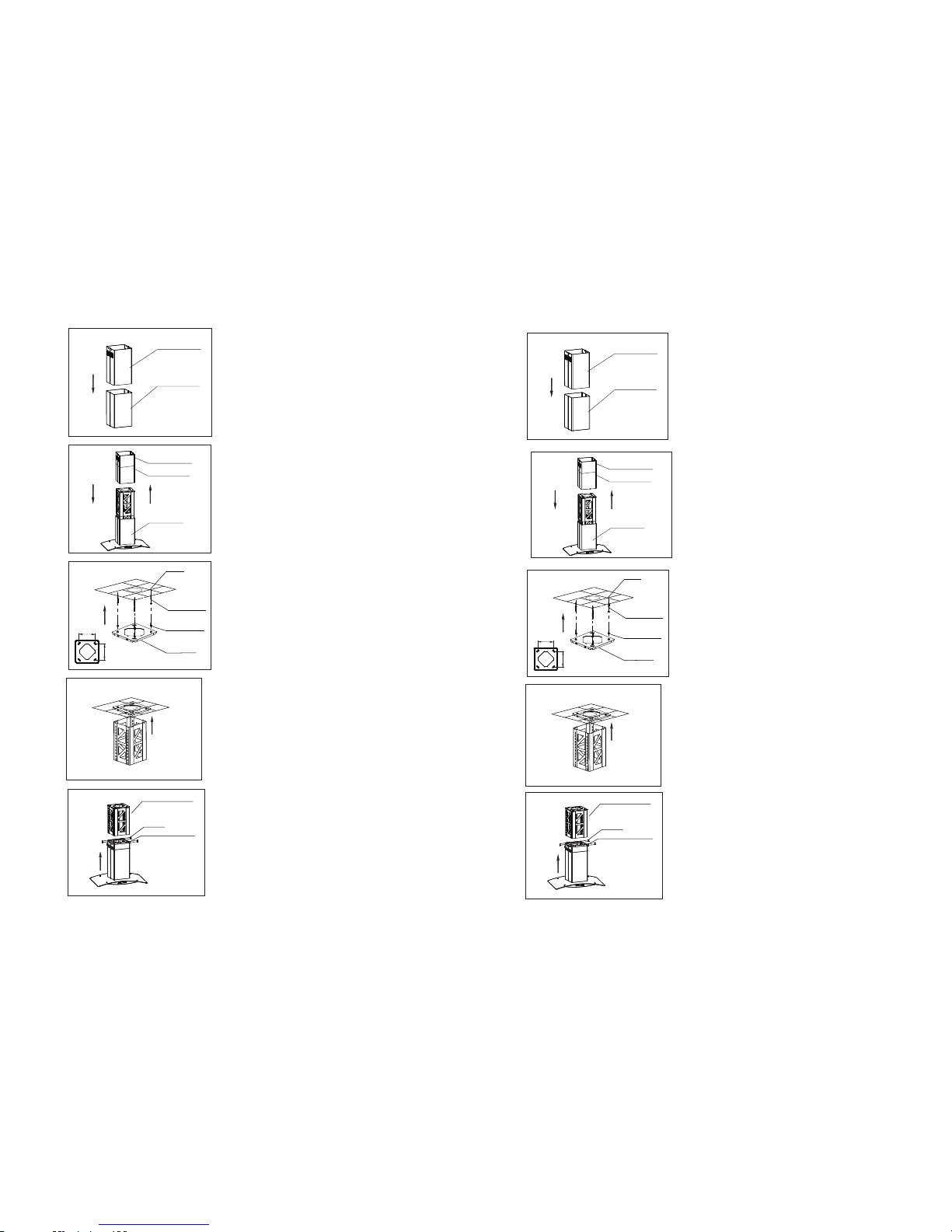
8
Upp er duct c over
Low d uct cov er
Step 4:
Inser t th e up per duct co ve r in to the low
duct co ve r.
Blower box assembly
Low d uct cov er
Upp er duct c over
Step 5:
Put the up pe r an d lo w du ct c ov er o n th e
blower box a ss embly.Then pull out the
exhaust pipe to th e le ve l of t he u pp er
duct cover.
Ceiling
Expanding Rubber
Expanding Screws
Ceiling cover
238
238
Step6 :
As per th e sc re w positio ns o n th e Upper
suppo rt f ra me, drill 4 h ol es ( about φ8 mm) ,
then fi ll t he E xpandin g Ru bb er into the
holes . Aim in g the hol es o n th e ce iling c ov er,
fix the c ei li ng cover wi th t he e xpandin g
screw s ti gh tly and mak e su re i t is firm.
Step 7:
Put upp er s up port fram e un de r the ceili ng
cover. U se s cr ews to fi x th e up pe r suppo rt
frame t o th e ce iling cov er.
Step 8:
Shift t he c om plete chi mn ey , to make the
low sup po rt f rame cove r th e up per suppo rt
frame . Adj us t its hei gh t. F ix i t tight ly w it h
8 pcs M4x 10 s cr ews and mak e su re t hey are
firm.
Upper support frame
Screws
Low support frame
8
Pas o 7
Ubique e l so po rt e su pe ri or d eb aj o de l a
cubier ta d el t ec ho y u ti li ce t or ni ll os p ar a
fijarl o.
Pas o 8
Desl ic e la c hi me ne a de m an er a ta l qu e cu bra
el sopor te f ij ad o en e l pa so a nt er io r.
Sopo rte sup erior
Tornil los
Sopo rte mas b ajo
Techo
Tubo de ex pansi nó
Tubo de ex pansi nó
Cubi erta de l techo
238
238
Pas o 6
En referencia a la posición de los torni ll os e n
el sopor te s up er io r, per fore 4 huecos
(alrededor d e 8 mm d e di ám et ro ), l ue go l le ne
con las piez as d e go ma s ex pa nd ib le s en l os
mismos . Ap un te l os h ue co s en l a cu bi er ta d el
techo, ármela con los tornil lo s ex pa nd ib le s
de manera tal que quede firme.
Pas o 5
Pon ga l a cu bi erta del ducto inferior y
superi or a nt es a rm ad a en ci ma d e la c aj a de
soplad o en sa mb la da . Lu eg o ha le l a tu be rí a
de gas has ta e l ni vel de l du ct o su pe ri or.
Cubierta del ducto externo
Cubierta del ducto inter no
Ensa mblaj e de la
caja d el venti lador
Cubierta del ducto inte rno
Cubierta del ducto externo
Pas o 4
Inserte la cub ie rt a de l du ct o su pe ri or e n la
cubier ta d el d uc to i nfer io r.
Page 11
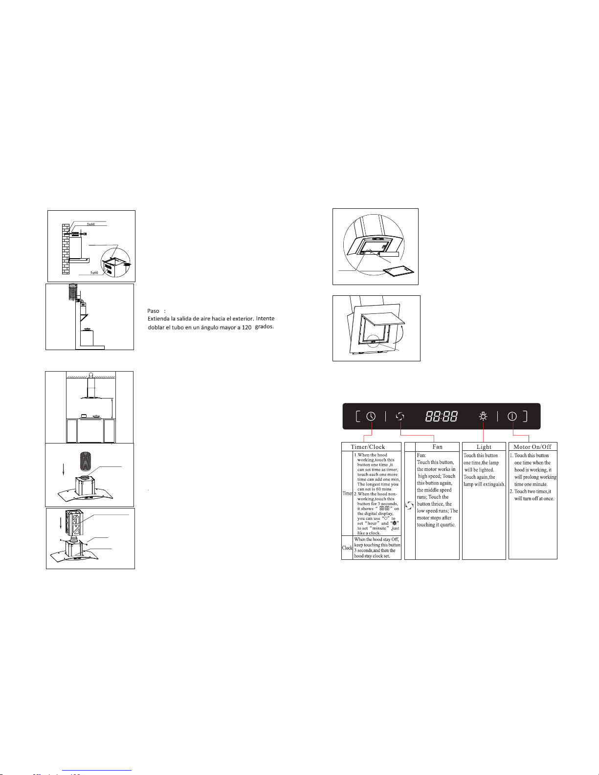
9
Step 9:
Insta ll p yr amidica l fi lt er. Matc h th e fi x pi n
to the fi x ho le a nd button t he f il ter gentl y as
the dir ec ti on of arrow A.
Filt er
Fix ho le
A direc tion
Cautio n be fore c ooking:
FOR P CH 99 0R,PC H96 0R:
Whe n coo king, no ne ed open the gl ass p anel.
If yo u wan t to op en th e panel when c lea n,
jus t ope n like this pi ctu re in the
arr ow po sitio n tig htly.Note that t he pa nel
can ’t fi x its elf after op eni ng.
lock
OPERATIO N IN ST RU CT IO N
PCH 762DR & P HC767 DR & PHC7 97DR
7
Pas o 2
Saque la chi me ne a de l a ca ja y q ui te e l fi lt ro ,
luego póng al o so br e un a ta bl a de t rabajo
horizontal s uavemente. Arme la t ub er ía d e
gas dent ro de la s al id a de a ir e, e st e se gu ro
de que est é co ne ct ad a fu er te d e ma ne ra tal
que qued e ap re ta da .
sali da de air e
Pas o 3
Apunte e l so po rt e in fe ri or a l os h ue co s en l a
caja de sopl ad o en sa mb la da , y lu eg o ár me la
de manera que quede apretada. Luego hale
la tuber ía d e ga s ha st a el n iv el d el s op or te
inferior.
Sopo rte infe rior
Tornil lo
Ensa mblaj e de la
caja d el venti lador
Tubo de ex pansi nó
Tornil lo de mad era
Tubo de ex pansi nó
Tornillo de madera
Pas o 5:
1)Extiend a la c ub ie rt a in te rn a a la a ltura
deseada. Ma rq ue d os o ri fi ci os d el gancho del
ducto int er no e n la p ar ed .
2)Pon ga l a cu bi er ta d el ducto inte rn o
suave me nt e us an do u na b roca de 8 mm para
perfo ra r do s or if ic io s de 60-70 mm de
profu nd id ad e n la p ar ed q ue usted acab a de
marcar.
3)Presi on e lo s tu bo s de e xp an si ón dentro de
los orifici os
4)Extiend a el d uc to e xt er no y a pr ie te los dos
tornillos d e ma de ra 5 x6 0 de ntro de los t ub os
de expansió n.
INSTALAC IO N PA RA MODELO S PC H8 96 IR
650- 700mm
Pas o 1:
Por f av or p onga la cam pa na e n la p ar ed y
marque la p os ic ió n en l a qu e la d es ea i nstalar.
Rec om en da mo s qu e la a lt ura des de l a es tu fa
hasta la pa rt e in fe ri or d e la c am pana debe ser
entre 650 m m ha st a 70 0 mm .
6
Page 12
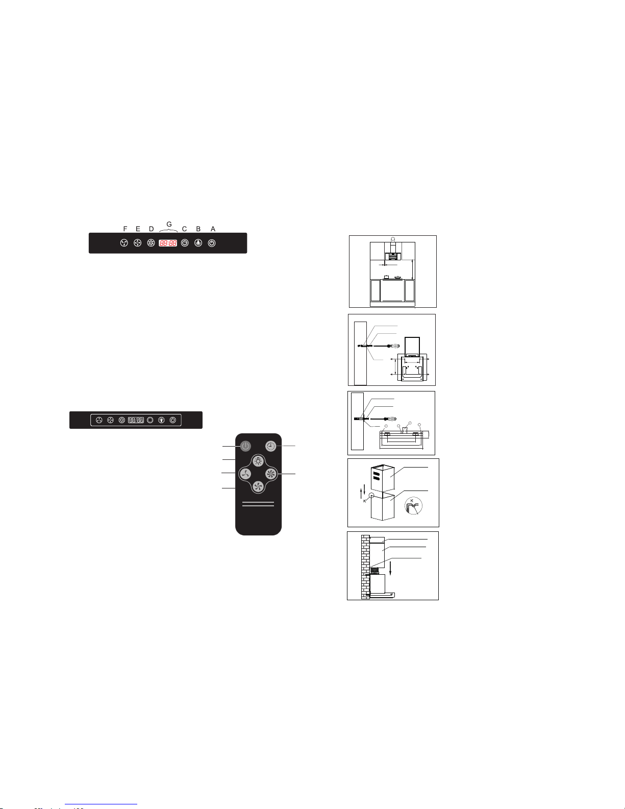
PCH 796DR &PCH9 90R&P CH960 R
A: Touch A , the fa n runs at t he low sp ee d. Pr ess it ag ain, th e fan tur ns off.
B: Touch B, t he f an ru ns at the m id spee d. Pres s it agai n, the fa n turns o ff.
C: Touch C, t he f an ru ns at the h igh spe ed. Pre ss it aga in, the f an turn s off.
A、B、C thr ee bott ons int eract .
D: Wh en the ho od s tay O FF, ke ep t ouc hing D 3s , and the n touch C a nd E to adj ust hou r
and m inute , at that t ime, G ju st like a c lock.
Whe n the hoo d is oper ating , t ouch D to c ontro l worki ng time o f hood, 5 m inute s per
one t ouch, t he long est sta y ON time i s 60 minu tes.
E: Touch E, t or n on th e light . Press i t again , turn of f the l ight.
F: Wh en the ho od i s ope ra tin g , touch F, t he ho od will n ot be OFF a t once, i t will st ay
one m inute , and the n be OFF.
PCH 794DR
This switch is highly-sensitive touch control, use your figure touch the key-press slightly to operate it.
And this switch with gas sensor and heater sensor function.
F
A
B
E
D
G
A. Motor on/off: Touch one time when the hood in working, it will
continue working one minute, touch again two times it will turn off.
B. Lighting: Touch this button, the light will be lighted, touch
again the light will be extinguish.
C. Receiver: Direct the remote control at the receiver when use.
D. High speed: Touch this speed, the motor will work in high speed.
E. middle speed: Touch this speed, the motor will work in middle speed.
F. Low speed: Touch this speed, the motor will work in low speed.
,
G. Timer: touch this button one time when it s in working condition,
it will turn off in one minute. Touch one more time, one more minute
working time increased.
chang e of e le ctron
1.Open the electron cover,refer to pic 1.
2.When open,pls pay attention to the anode and cathode,refer to pic 2.
3.Take out the old electro and fix the new one and make sure the anode is as pic 3.
ABCDEF
10
6
Cubierta del ducto inter no
Cubierta del ducto externo
Ranu ra de
orie ntació n
Cubierta del ducto inter no
Cubierta del ducto externo
Tornillos de fijaci n
para el ducto externo
ó
Pas o 3:
Pon ga e l du ct o in te rn o en el ducto ext er no .
Teng a en c ue nt a que el ducto in te rn o de be
fijarse de ac ue rd o a la r an ura d e or ie nt ac ió n.
Pas o4 :
Pon ga e l du ct o ex te rn o en la carca sa d e la
unidad. Use d os t or ni ll os M 4x 10 p ara fij ar e l
ducto exter io r a la u ni da d.
3
2
165
229
250
40
Tubo de ex pansi nó
5x60
Tubo de ex pansi nó
Sopo rte
1
4
Paso 2
Perfore agujeros en la pared usando un perforador
de 8mm de diámetro. Use tres tornillos para fijar la
campana en la pared en los agujeros 1, 2, 3. Luego
use un tornillo M4X10 para fijar la campana en el
agujero 4, de manera de estar seguro de que no se
va a mover.
5x60
Sopo rte
A B
C
D
306
310
Tubo de ex pansi nó
Tubo de ex pansi nó
10mm
350- 400mm
Paso 1:
Por f av or p onga la cam pa na e n la p ar ed y m ar que
la posición e n la q ue l a de se a in st al ar.
Rec om en da mo s qu e la a lt ura des de l a es tu fa
hasta la part e in fe ri or d e la c am pana debe ser
entre 350 m m ha st a 40 0 mm .
INSTALAC IO N PA RA MODELO S PC H9 90 R& PC H9 60 R
Page 13
Pic 1 Pic 2 Pic 3
A B C D E
A : When t he ho od is ope ratin g, pres s butto n A( ), th e hoo d wi ll be o ff.
B :Pr ess but ton B( ),th e fan run s at the lo w speed .
C: Pr ess but ton C( ), t he fan ru ns at the m id spee d.
D :Pr ess but ton D( ), t he fan ru ns at the h igh spe ed.
E: Pr ess but ton E( ) on ce, tur n on the li ght. Pr ess it ag ain, tu rn off th e light .
PCH 760R
PCH896I R
A: Ti mer
1. When t he h oo d is w or ki ng, touch this butt on o ne t im e, t he h ood will
each one mo re t im e ca n ad d 1 mi nute, the longest t im e yo u ca n se t is 6 0
minutes .
2. When t he h oo d is n on -w orking, touch thi s bu tt on 3 s ec on ds, you can
use “Ligh ti ng ”a nd “ Sp eed”button to set tim e li ke a c lo ck ,“Lighting”
can set hou r, “Spe ed ” ca n se t mi nu te.
B: Lighti ng
Touc h th is b ut ton one time, the lam p wi ll b e li gh ted; Tou ch a ga in , th e
lamp will e xt in gu is h.
C: Spee d
Touc h th is b ut ton, the motor work s in h ig h sp ee d, touch this butto n
again, th e mi dd le s pe ed r uns; touch the butt on t hr ic e, t he l ow speed
runs; the m ot or s to ps a ft er
touchin g it q ua rt ic .
D: On/ Of f
This gene ra l On / Off button, t ou ch t hi s bu tton first before y ou t ou ch
other but to ns ; to uc h th is button when the ho od i s wo rk in g, t he motor
stops run ni ng , li gh ts t urn off .
A
B C D
11
5
Pas o 5:
Pon ga e l du ct o interno en el ducto externo.
Teng a en c ue nt a qu e el d uc to i nt er no d eb e
fijars e de a cu er do a l a ranura de o rientación.
Ducto i ntern o
Ducto e xtern o
Ranu ra de
orie ntació n
Pas o6 :
Pon ga e l du ct o externo en la carcasa de la
unidad. Us e do s to rn il lo s M4 x1 0 pa ra f ij ar
el ducto ext er io r a la u ni da d.
Pas o 7:
1)Exti en da l a cu bi er ta i nt er na a l a al tu ra
desead a. M ar qu e do s or if ic io s de l ga nc ho
del ducto inte rn o en l a pa re d.
2)Pon ga l a cu bierta del ducto interno
suavemente usando una broca de 8 mm
para perfor ar d os o ri fi ci os d e 60 -70 mm de
profundidad en la pared que usted acaba
de marcar.
3)Presio ne l os t ub os d e ex pa ns ió n de nt ro d e
los orif ic io s
4)Exti en da e l du ct o ex te rn o y ap ri et e lo s do s
tornil lo s de m ad era 5x60 den tro de l os
tubos de exp an si ón .
Cubierta del ducto intern o
Cubierta del ducto externo
Tornillos de fijaci n
para el ducto externo
ó
Tubo de ex pansi nó
Torni llo de ma dera
Tubo de ex pansi nó
Tornillo de madera
Pas o 8:
Extien da e l tu bo d e es ca pe a l tu bo d e
ventilación de su ed if ic io o h ac ia e l ex te ri or.
Trat e de h ac er u n do bl ez d el t ub o de
ventilación de más d e 12 0° .
Pas o 9:
Instale el fil tr o. Po ng a el p er no de fijación en
el ori fi ci o de f ij ac ió n y pr es io ne e l ga nc ho d el
filt ro suavemente en dirección a la flec ha A .
Agujero de
fijaci nó
Perno de fijaci nó
Direc ción
Page 14
MAINTENANCE
CAU TION: N EVER PU T YOU R HAND IN TO TH E AREA HO USING W HILE
THE FA N IS OP ERATING .
FOR T HE OPTI MA L LEVE L OF OP ERATION , CLEAN T HE RA NGE HOO D
SUR FACE, FAN , AND FI LTER R EGU LARLY.
1. Us e only mi ld soap o r deter gent so lu tio ns t o cle an the co oker ho od surf ace. Dr y
sur faces u sing so ft clot h.
2. Us ing a sta inles s steel c leane r to brin g the glo w back in to a stai nless s teel fi nish.
3. Cl ean the a lumin ium fil ter onc e a week or a ccord ing to us e statu s. Pres s the buc kle
of th e alumi nium fi lter sl ightl y, ta ke of f the alu mi niu m fi lte r and put i t into wa rm soap y
wat er usin g mild de terge nt, wip e th e fil te r wit h soft br ush. Re place t he filt er afte r it is dry.
4. Cl ean the m otor fa n and oth er insi de part s once ha lf year o r accor ding to u se by
QUA LIFIE D PERSO N.
5. DO N OT clea ning mo to r wit h wa ter o r other l iquid .
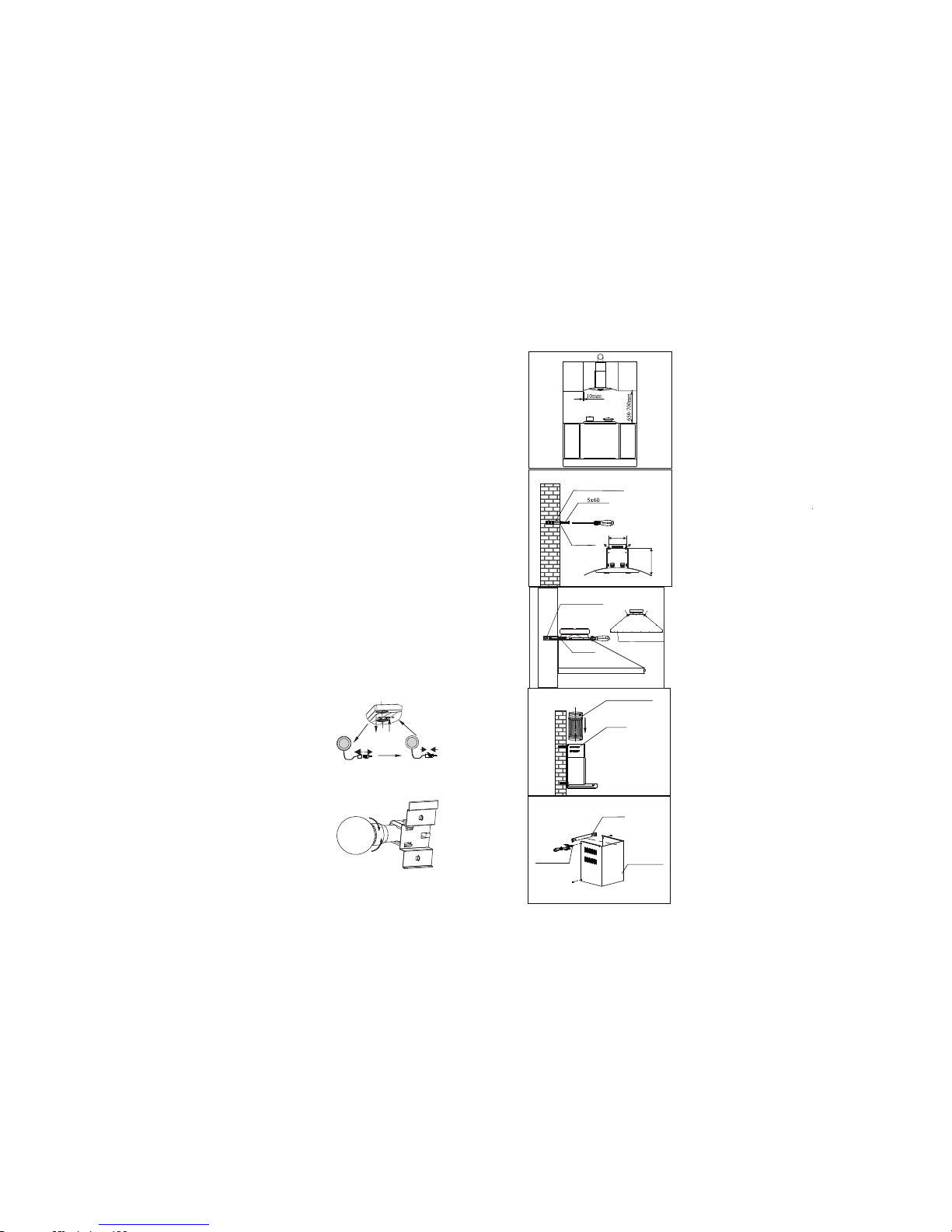
TO RE PL AC E LA MP
Cau tion: L ED lamp c an not re place a n ew bulb , just ca n repla ce a new LE D Lamp.
Mak e sure al l the con trol sw itche s are off , and he co ok er ho od i s unp lugge d!
Ple ase fol low bel ow inst ructi ons:
1.Ta ke out th e filte rs , and c ut off th e wire co nnect io n of th e lamp.
2.P ress th e sprin g accor ding to t he arro w direc tion, t hen
you c an take o ff the la mp unit .
3.You c an repl ace a new L ED lamp u nit no mo re then r ating !
4. Th en put th e la mp un it t o the h ood in re verse d irect ion. Co nnect t he wire o f the lam p.
5. Fi t on the fi lters .
To repl ac e nor mal lam p bulb( Pic.2 )
Cau tion :l amp uni t may be ho t! Wait unt il the un it is coo l.
And u se the sa me type l ight bu lb!
Mak e sure al l the con trol sw itche s are off , and the c oo ker h oo d is un plugg ed! Ple ase fol low
bel ow inst ructi ons:
Warn ing : Make su re the bu lb is coo l befor e you tou ch it!
1.Ta ke out th e filte rs .
2.L oose th e old lig ht bulb .
3.R eplac e a new lig ht bulb w hich is t he same t ype no mo re
tha n ratin g!
4.F it on the f ilter s.
To repl ac e LED lamp (P ic.1)
Pic .2
Pic .1
12
4
INSTALAC IO N PA RA MODELO S PC H7 60 R, PC H7 62 DR,PCH794 DR ,P CH 79 6D R,
PCH767DR, PC H7 97 DR
Pas o 1:
Por f av or p on ga l a ca mp an a en l a pa re d y
marque la posici ón e n la q ue l a de se a in st al ar.
Recomendamos que la altura desde la estufa
hasta la par te i nferio r de l a ca mp an a de be s er
entre 650 mm has ta 7 00 m m.
Pas o 2:
Marque los cuatro aguj eros e n la p ared d e la
forma que aparece en esta fi gu ra. Tala dr e 4
agujeros de 8 mm de diám et ro y 6 0- 70 m m de
profundidad en la pared donde usted los
marcó. Presione lo s 4 tu bo s de e xp an si ón
dentro de los ag uj er os . Ap ri et e lo s 4 to rn il lo s
de madera de 5x60 mm que se proveen dentro
de los tubos d e ex pa ns ió n. A se gú re se q ue
esté n su fi ci en te me nt e ap re ta do s y qu e no s e
puedan mover.
232mm
B
A
Tubo de ex pansi ón
Tornil lo de mad era
Gan ch o
Pas o 3:
Fije el tubo d e es ca pe ( 15 3 mm d iá me tr o de
lado) al cie rr e.
Pas o 4:
Fije el ganc ho d el d uc to i nt er no c on l os
tornil lo s M4.
Tubo de e scape
Cier re
Sopo rte
Tornil lo M4
Duct o interi or
A
B
Expa nding Tu be
Back o f the hoo d
5x60
Wood Scr ew
Page 15
*Fig
It’s adv is ab le to cal l qu al if ied &au th or iz ed Serv ic e pe rs on for pe ri od ic ally
clean in g th e interna l as se mbly;sa me w ou ld be great ly i mp rove the
perfo rm an ce of the pro du ct s.
Note: -i f du e to any reas on i f yo u don’t u se t he cooker h oo d ,o il/fat ma y
depos ed o n th e filter& su rf ace of the ch im ne y if may star t dr ip ping&ca n ca us e
the fir e al so .
Note: - be fo re carryi ng o ut t he mainte nc e cl eaning or r ep la cing the la mp ,
disco nn ec t the cooke r ho od f rom the mai n su pp ly(remo ve t he p lug from th e
socke t. )
Re-ci rc ul ation Mod e
Check t ha t ac tivated c ha rc oal filte rs a re f itted pro pe rl y, so th at t he i mp urite s
can be ef fective ly a bs orbed.
The coo ke r ho od better t o be o pe rated at th e se co nd or lowes t sp ee d so that
suffi cient tim e is a va ilable fo r th e fi ltratio n of t he a ir.The act iv at ed charco al
filte rs c an n’t b e re -u sed&nee ds p er iodical c ha ng e.The lif e of t he a ctivate d
charc oa l fi lters are a bo ut 3 t o 4 months. Ho we ver if the co ok er h ood is used
more th an 4 h ou rs a day&la rge amoun t of o il i s used whil e co ok ing then
charc oa l fi lter may re qu ir e more freq ue nt r eplacem en t.
*The ch ar co al filter h av e to b e changed a s so on
as they s at ur eated.T he y ca n be eaily re pl ac ed
by turn in g th em anti clo ck wi se for remo vi ng
&cloc kw is e to fefit th em . Fi g.
Ducti ng M od e
No need i ns ta ll charco al f il ter,exhaus t ou ts ide.
If you si de c an e xhaust ou ts id e,then we s ug ge st
you cho os e th is mode for b et te r perform an ce .
Whate ve r re -circul at io n Mode or duc ti ng m ode
you cho os e, Cassett e fi lt ers need to b e cl ea ned
evey on e mo nt h.But thi s ma y va ry on usage
patte rn a ls o.In case l arge amou nt o f oi l is used
for coo ki ng , same has to b e cl ea ned every w ee k
/fort ni gh t. Filter s ca n be e asily cle an ,j ust put the m
in a soap s ol ut ion of hot wa te r& clean wit h a br us h
&then r in se u nder a runn in g ta p water&w ap e wi tha dry clo th .R efix the fi lt er s
prope rl y. Instr uc ti on s for rem ov in g &f or refi t Pu sh t he f ilter l oc k ba ck ward to
relea se t he f ilter fro m th e sl ot.
NOTE: Us e of o ptional c ha rc oal filte r or d uc ting mode i s le ft t o the insta ll er.
IMPORT AN T NOTICE
13
A
3
LEVEL
Fig .4
LEAN
650~7 00mm/
350-4 00mm
Fig .1 Fig .2 Fig .3
Nivel ad o Incli na do
1. No instal e la c am pa na e xt ractora donde haya mu ch as p ue rt as o v en ta na s,
esto es de bi do p ara evitar afectar la efic ac ia d el e xt ractor cau sa da p or e l fl uj o
de aire(Fig. 1).
2. Instale la camp an a co rr ec ta me nt e en ci ma d el t op e de c oc in a. L a di st an ci a
recomendad a en tr e el t op e y el b or de m ás b aj o de l a ca mp an a pa ra m od el os
PCH760 R, PC H7 62 DR ,P CH 79 4D R, PC H7 96 DR ,P CH 767DR,PCH797DR,PC H8 96 IR
es de 650mm a 70 0 mm ( Fi g. 2 ). L a di st an ci a
recomendad a en tr e el t op e y el b or de m ás b aj o de l a ca mp an a pa ra m od el os
PCH990 R, PC H9 60 R es d e 35 0m m a 40 0m m (F ig . 2) .
3. Pa ra u n fu nc io na mi en to o pt im o, n o al ar gu e el t ub o de e sc ap e de ma si ad o,
por lo que int en te d ob la r el t ub o de e sc ap e me no s y el m ás g ra nd e pa ra l og rar
que la conex ió n se a he rm ét ic a (F ig . 3) .
4. Después de colgar la un id ad e n la p ar ed , as eg úr es e qu e la c am pa na e st e
vertical y nivelada.
5. El ducto de a ire no se de be c on ec ta r a lo s tu bo s de l a ch im en ea o l os
conducto s de l ga s de c om bu st ió n. E l du ct o de a ir e no s e de be c on ec ta r ba jo
ninguna ci rcunst an ci a a lo s co nd uc to s de v en ti la ci ón p ar a un a ha bi ta ci ón e n el
cual exi st a al gú n ap arato de combu st ió n.
6. La campana pu ed e se r in st al ad a de c ua lq ui er m an er a, ya sea modo
recirculación o de duccion . Todo s lo s mo de lo s fu er on r ec ie nt em en te i ns talados
con filt ro s de c ar bó n en m od o re ci rc ul ac ió n. S i us te d qu ie re m od o du cc io n,
entonc es q ui te l os f il tr os d e ca rb ón .
Requis it os d e in stalación
Page 16
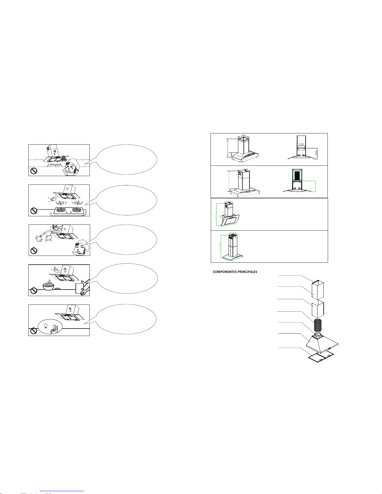
Man ual
Do clea n the hoo d
corre ctly in a ccord ance
with in struc tion st ated or it
might c ause th e possi bility
of fire a ccide nt
To replace t he bulb
shoul d be unde rtake n by a
quali fied el ectri cian or a
compe tent pe rson. Alw ays
use the b ulb no mo re
than ra ting.
IMPORTANT SAF ET Y INS TR UC TI ON S:
In case o f any
damag e to powe r cable ,
repla ce the br oken ca ble with
a new one b y quali fied pe rson.
Do not co nnect t he air
outle t to chim ney flu es or
combu stion g as duct s.
Do not le ave nak ed
flame s under t his hoo d
14
2
PCH 797DR 6 88/GS 14
895
480
500-880
300
283
341
232
A
B
A
B
PCH 796DR
300
283
525-920
115
475
895
595/8 95
Ducto telescopico interno
Ducto telescopico externo
Filtro de aluminio
Tubo de escape
Cubierta inferior
Soporte del ducto
Salida de aire
Page 17
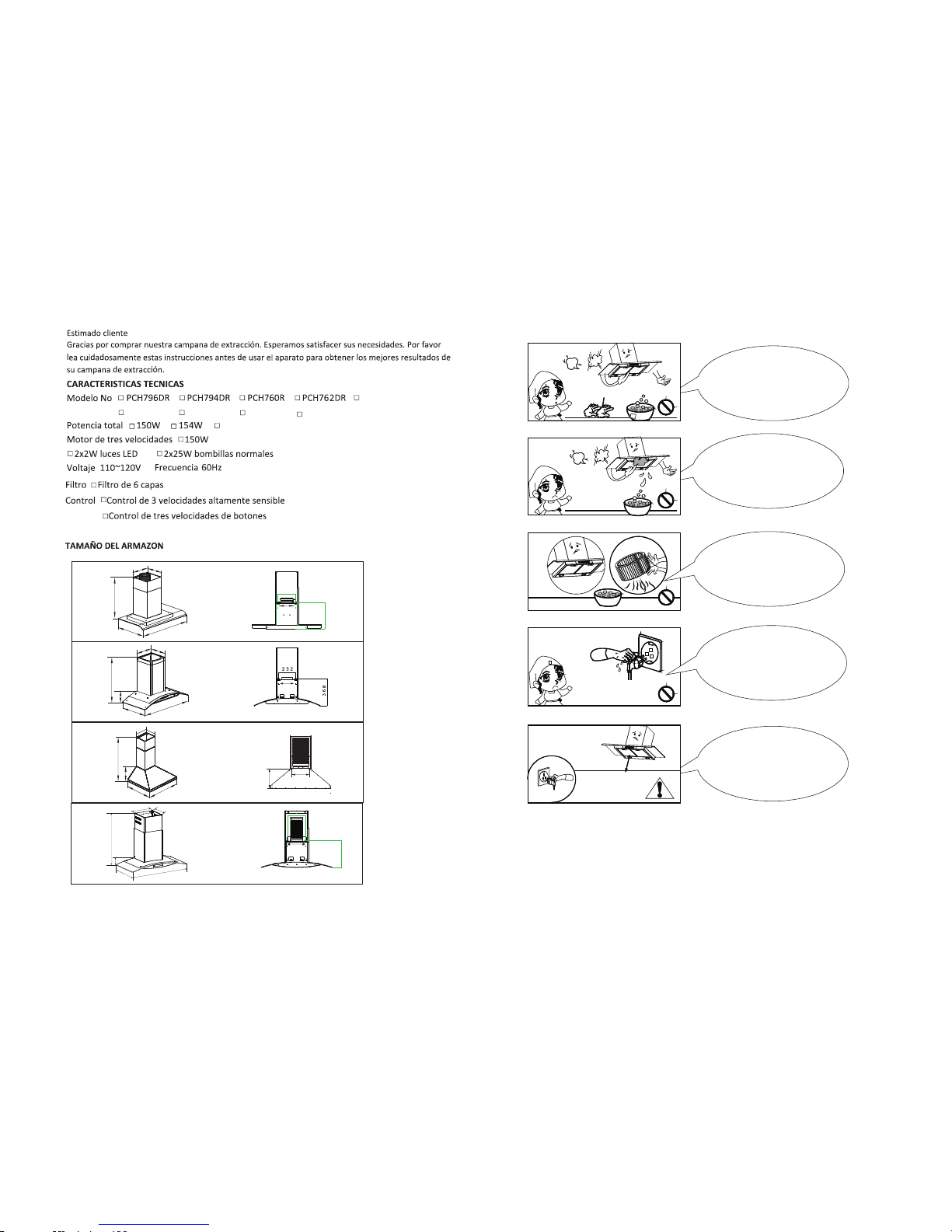
Dress t he prot ectiv e
glove b efore y ou star t to
clean t he hood . Remov e the
compo nents g ently d uring
carry ing out t he
clear ance.
Never w ash the
contr ol swit ch with w ater
or othe r kind of l iquid t o avoid
the liq uid mig ht caus e
elect rical p roble m to
the hoo d.
To clean the m otor
fan sho uld be un derta ken
by a qual ified p erson , pay top
atten tion to a void an y distortion
of the fa n durin g carry ing
out the c leara nce.
Nev er pull t he plug
out o f the pow er supp ly by
wet h and to av oid the
pos sibil ity of el ectri c
sho ck.
Disco nnect t he
cooke r hood fr om the
power s upply i f this ap pliance
will no t be used f or
a long ti me.
Glo ve
15
1
PCH 760R 63 160不带 方 边15 0风 机
597
487
189
530-920
186
213
200
180
A
B
PCH76 2DR 66 8S (6 0) /GS 14
295
285
509-900
59
475
595
PCH 794DR
30
0
283
895
480
500-880
PCH 767DR 6 88(60 )/GS1 4
595
480
48
483-873
283
300
A
B
232
339
341
232
A
B
A
B
PCH 767DR
PCH 797DR
PCH 990R
158 W
PCH 896IR
Page 18
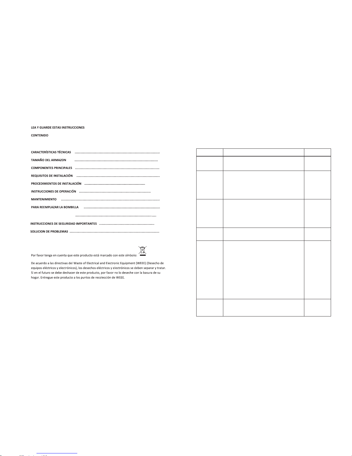
STATUS
CAUSE AND METHOD OF REPAIRING
The p ower
sup ply is
dam aged
If the po wer sup ply is da maged,please cal l
techn ician s to repa ir.
the
The mot or does
not run
a) The motor was broken, repla ce a new mo tor
assem bly.
b) The switch control was brok en, rep lace a ne w
switc h contr ol.
c) The capacitance was broke n, repl ace a new
capac itanc e.
a) The installation is not fir m enoug h. Chec k it and
make su re the ho od is fir m enough.
b)The f an is bro ken, so i t is not balance. Repl ace a
new mot or asse mbly.
c) The motor does not firm enoug h. Chec k it and
insta ll it fir mly eno ugh.
a) Some o ther th ings dr op to the blower. Check and
clean i t.
a) The distance from the cooke r hood to t he gas
cooke r is too bi g. Make s ure the distance is ab out
650-7 00mm.
b) There are many windows or doo rs in the k itche n,
the air c onvec tion is t oo big. Close some doo rs or
windo ws, sma ller th e air convection.
c) There have some other pour wi nd to the e xhaus t
pipe. M ake the e xhaus t pipe’s exit to dow nwards.
d) The run rate of motor decreas e obvio usly. Repl ace
a new mot or or cap acita nce. Because of the co oker
hood is s et upon t he wind ow, the bes t solut ion is
that pu t one thr eeply b oard on the back of the
cooke r hood fo r cover ing the hollow of wind ow.
Bulb do es not
work
Repla ce with a n ew LED la mp assembly.
TOOL
"+" t ype
Scr ewdri ver
Sha rp Pinc ers
"+" t ype
Scr ewdri ver
"+" t ype
Scr ewdri ver
"+" t ype
Scr ewdri ver
"+" t ype
Scr ewdri ver
"+" t ype
Scr ewdri ver
The uni t body
shake
Big noi se
Sucti on not so
power ful
TROUBL E SH OOTINGS
CAUTI ON : Di sconnec t th e po wer suppl y be fo re servic in g.
16
9- 1 0 -1 1
12
12
14 - 1 5
16
1
1- 2
2
3
4- 5 - 6- 7 -8
Nota Imp or ta nt e
13
 Loading...