

Page 1

Alarm Cards
Reference Guide
Publication 999-001967
Revision A1
Release 3.9
October 1999
Page 2

Running Head
Trademarks:
5ESS
DMS-100 and DMS-200 are trademarks of Northern Telecom.
Nortel is a trademark of Northern Telecom.
HyperTerminal is a registered trademark of Microsoft
Premisys is a registered trademark of Premisys Communications, Inc.
SLC is a registered trademark of Lucent Technologies
Windows 3.1 and 95 are registered trademarks of Microsoft
All other trademarks and registered trademarks are the property of their respective holders.
FCC Registration number:
1H5SNG-73866-DD-E (integral CSU)
B468NR-68618-DM-E (internal modem)
is a registered trademark of Lucent Technologies
Model No.
Canadian Certification number : 1932 5217 A
Canadian DOC Load number: 5
Ringer Equivalence Number: 0.2A (internal modem)
Approvals:
UL listed to UL# 1459 Second Edition, Third Edition
CSA listed to C22.2 No. 950-M89
COPYRIGHT
©
1992-1999 Premisys Communications, Inc. All rights reserved.
This publication is protected by federal copyright law. No part of this publication may be
copied or distributed, transmitted, transcribed, stored in a retrieval system, or translated into
any human or computer language in any form or by any means, electronic, mechanical,
magnetic, manual or otherwise, or disclosed to third parties without the express written
permission from the manufacturer.
The manufact urer makes no representation or warranties with r espect to the contents hereof
and specifically dis claims any implied warran ties of merchantabil ity or fitness for a par ticular
purpose. Further, the manufacturer reserves the right to revise this publication and to make
changes from time to time in the contents her eof without obligatio n from the manufacture r to
notify any person of such revision or changes.
Page 3

Produ ct Description
The Alarm C ards
systems. Each card also receives alarms report ed by external devi ces. Each card has switches
for outbound alarms, and sensors that detect incoming alarms from the external equipment.
allow the system to report alarms to external alarm annunciators and other
Alarm Cards
ALR ALR 4+4 (8401), ALR 4+3PF (8402), ALR 28+14 (8403)
•
Using this Alarm Card Reference Guide
This Alarm Card Refe rence Guide as sists tech nicians with
configuration, and troubleshooting information for the Alarm
Chapter 1.
Alarm Card
switch settings, conne ctor pinouts ,
Cards.
Page 4

Running Head
Model No.
Page 5

Contents
Chapter 1 Alarm Cards
1.1 Introduction ....................................................................................................1-1
1.2 Alarm Card Descriptions ................................................................................1-1
1.2.1 ALR 4+4 Card Description (8401).............................................................1-1
1.2.1.1 Card Jumpers/Switch Settings................................................................1-2
1.2.2 ALR 4+3PF Card Description (8402)........................................................1-2
1.2.2.1 Card Jumpers/Switch Settings................................................................1-2
1.2.3 ALR 28+14 Card Description (8403).........................................................1-4
1.2.3.1 Card Jumpers/Switch Settings................................................................1-4
1.2.3.2 Installing the Alarm Card.......................................................................1-9
1.3 Alarm Card User Screens and Settings ........................................................1-10
1.3.1 Alarm Filter Screen Sensor Setting..........................................................1-10
1.3.2 ALR 4+4 and ALR 4+3PF Card Main Screens........................................1-12
1.3.3 ALR 28+14 Card Screens and Settings....................................................1-14
1.3.4 Alarm Sensor Screen................................................................................1-14
1.3.5 Alarm Switch Screen ................................................................................1-16
1.3.6 Voice Screen...................................................................................... ......1-18
1.4 Alarm Card Error Messages .........................................................................1-22
1.5 Alarm Card Troubleshooting .......................................................................1-22
Contents
Alarm Cards
i
Page 6

Running Head
Contents
Model No.
ii
Alarm Cards
Page 7

Figures
Figures
1-1 ALR 4+3PF Card.................................................................................................................1-3
1-2 ALR 28+14 Card Settings....................................................................................................1-5
1-3 Active and Passive Alarm Sensor Modes............................................................................1-7
1-4 Jumper Pair Assignments.....................................................................................................1-8
1-5 Jumper Installation for Active Mode...................................................................................1-8
1-6 Jumper Installation for Passive Mode..................................................................................1-9
1-7 Alarm Filter Screen............................................................................................................1-11
1-8 ALR 4+4 and ALR 4+3PF Card Main Screen...................................................................1-12
1-9 ALR 28+14 Alarm Sensor Screen.....................................................................................1-14
1-10 ALR 28+14 Alarm Switch Screen.....................................................................................1-16
1-11 ALR 28+14 Voice Screen..................................................................................................1-18
Alarm Cards
iii
Page 8

Running Head
Figures
Model No.
iv
Alarm Cards
Page 9

Tables
Tables
1-1 ALR 4+4 and ALR 4+3PF Card Main Screen Actions...................................................1-12
1-2 ALR 4+4 and ALR 4+3PF Card Option Settings and Defaults ......................................1-13
1-3 ALR 28+14 Alarm Sensor Screen Actions......................................................................1-15
1-4 ALR 28+14 Alarm Sensor Option Settings and Defaults................................................ 1-15
1-5 ALR 28+14 Alarm Switch Screen Actions.....................................................................1-17
1-6 ALR 28+14 Alarm Switch Option Settings and Defaults ...............................................1-17
1-7 ALR 28+14 Voice Screen Actions.................................................................................. 1-19
1-8 ALR 28+14 Voice Option Settings and Defaults............................................................1-19
Alarm Cards
v
Page 10

Running Head
Tables
Model No.
vi
Alarm Cards
Page 11

Alarm Cards Introduction
Chapter 1
Alarm Cards
1.1 Introduction
This chapter provides installation, configuration, and troubleshooting information for the
Alarm cards. These cards are labeled as the ALR 4+4 (8401), ALR 4+3PF (8402), and ALR
28+14 (8403) Cards on their faceplate ejectors.
The Alarm cards allow the system to report alarms to external alarm annunciators and other
systems. Each card also receives alarms report ed by external devi ces. Each card has switches
for outbound alarms, and sensors that detect incoming alarms from the external equipment.
Only one Alarm card can reside in the integrated access system at a time. These cards are
discussed below.
Each card has two alarm notificat ion modes. The "Switch/Act On" (outbound) func tion allows
you to report inte rnal system alar ms to external devices, such as bu zzers, bells, and lights. The
"Sensor/T rig On" (inbound ) function allows you to receive externa l alarms through sens ors on
the card.
1.2 Alarm Card Descriptions
1.2.1 ALR 4+4 Card Description (8401)
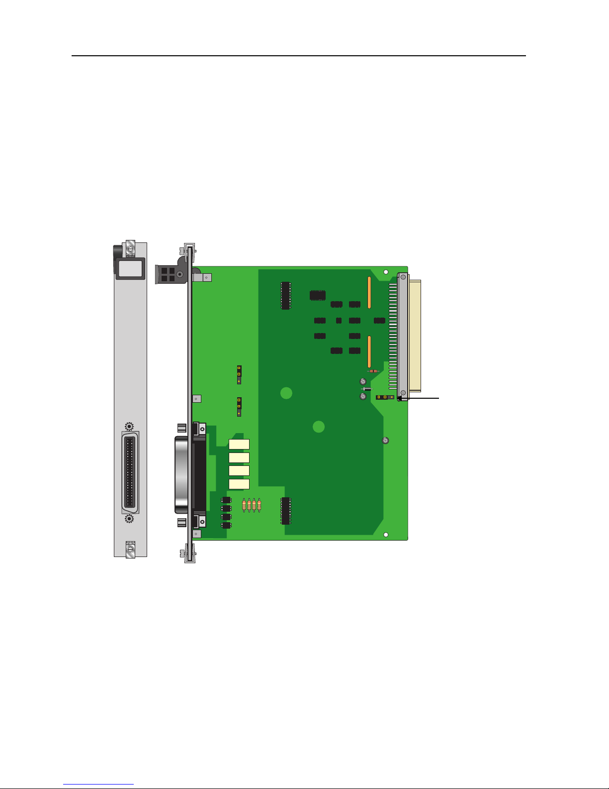
The ALR 4+4 Card has four outbound alarm switches and four inbound alarm sensors. The
outbound switches report internal alarms to external devices by triggering form-C relay
contact closures (120 VAC, 0.5A). The inbound sensors report extern al alar ms to the sys tem.
All external alarms reported by sensors are listed in the alarm history file.
An integrated access system with an ALR 4+4 Card can respond to four external alarms for
control of environmental and securi t y condit i ons, and also provide four internal alarms to
outside alarm indicators. For example, a critical alarm can illuminate a red light at the office.
Each inbound alarm sensor has the capability of responding to one external condition. The
alarms appear on the screen in the al arm sect ion, showi ng the al arm as a SENSOR ala rm and
includes the slot number and sensor number of the condition (e.g., SENSOR U7-4).
The inbound alarm sensors can be optioned to utilize either 12V or 48V. Both JP1 and JP2
jumpers should be set for the proper voltage. The inbound sensors are isolated from ground.
Alarm Cards
1-1
Page 12
Running Head
Alarm Card Descriptions Alarm Cards
Model No.
Each outbound "floating" relay has normally open contacts and normally closed contacts. It
responds to major , crit ical, minor, and inf ormational alarms, and a ctivates an ex terna l device.
T wo relays are provided for e ach Alarm Card port. The relays are dual-pole, double-thro w. See
Figure 1-1.
1.2.1.1 Card Jumpers/Switch Settings
The US/Euro jumper pair on t he ALR 4+4 car d must be con figured to t he same set ting as t hat
of the chassis. The factory default setting for cards and chassis is US position.
ALR
4+4
US/Euro
Jumpers
P
1
Figure 1-1. ALR 4+4 Card
1-2
Alarm Cards
Page 13
Alarm Cards Alarm Card Descriptions
1.2.2 ALR 4+3PF Card Description (8402)
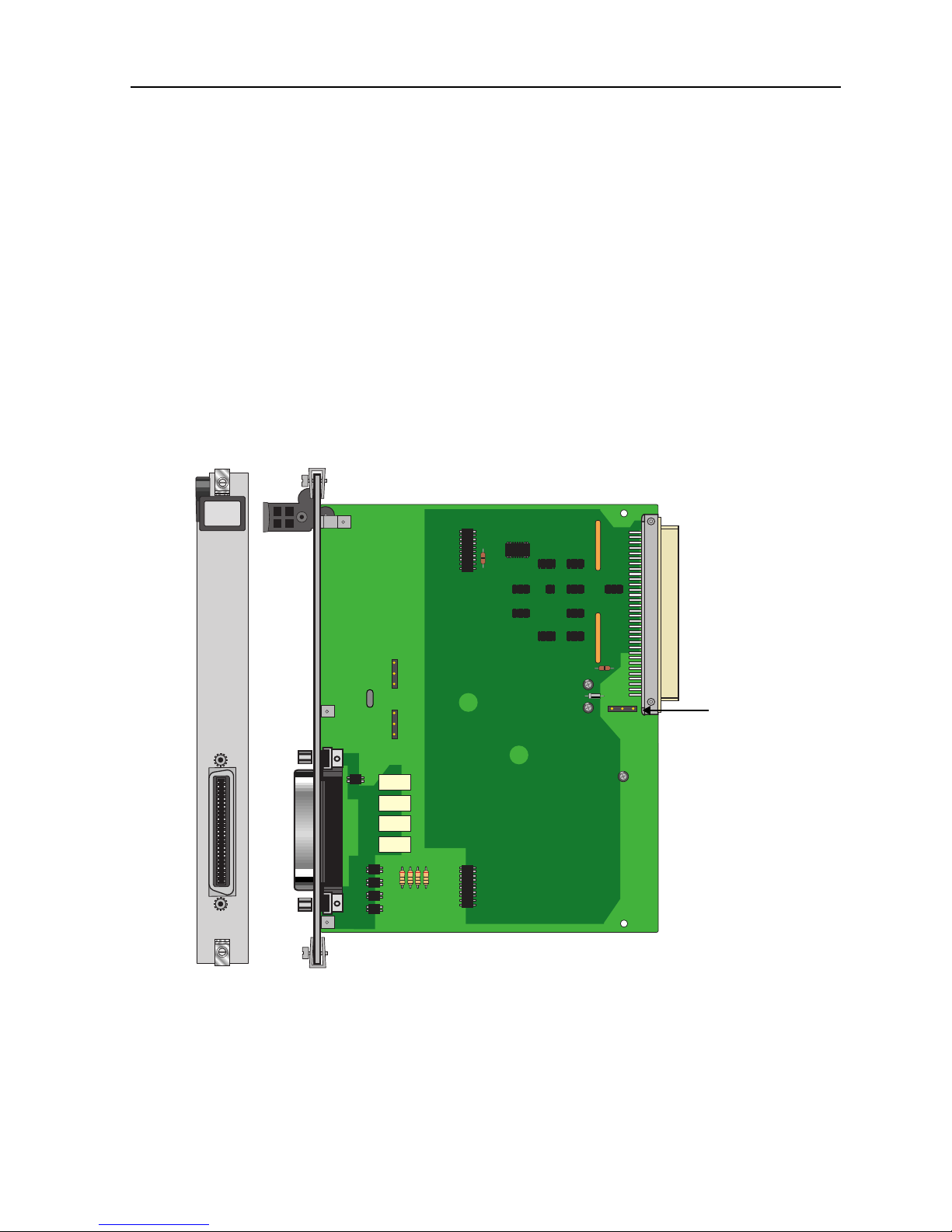
The ALR 4+3PF Card has four outbound switches and three inbound sensors. This card is
similar to the ALR 4+4 Card, except tha t its fourth alarm port can only be used as an
alarm to show the system power unit has failed. The ALR 4+3PF Card is especia lly helpful in
locations where a loss of power to any system units is a critical problem. See Figure 1-2.
outbound
A -48 VDC power source is optional with this card.
AC-to-DC Converter or an external source.
1.2.2.1 Card Jumpers/Switch Settings
There are US/EURO jumper settings with the ALR 4+3PF card.
ALR
4+3PF
It may be provided by either an
US/Euro
Jumpers
P
1
Alarm Cards
Figure 1-2. ALR 4+3PF Card
1-3
Page 14

Running Head
Alarm Card Descriptions Alarm Cards
Model No.
1.2.3 ALR 28+14 Card Description (8403)
The ALR 28+14 Card has 28 sensors for incoming external alarms. Each sensor controls its
own alarm. The card also uses 14 switches to control external devices, and provides a single
FXS voice port.
The sensors allow you to connec t up t o 28 e xterna l devi ces t o the card. The se sen sors ma y be
powered either externally or from the alarm card. They are divided into two groups, with 14
sensors per group. Each sensor group is routed thr oug h one of t w o Amphenol jacks, and you
can control the voltag e to each gr oup by operat ing a volta ge control switch on the al arm card.
Detailed i nstructions for sensor contr ol are provided later in this chapter.
The switches allow the card to control up to 14 external devices. As with the sensors, the
switches are divided between the two Amphenol connectors into two groups of seven swi tches
each. Twelve of the switch es are Form C (open or clo sed bas ed on us er inp ut), on e i s Form A
(always open), and one is Form B (always closed). One of th e swit ches can also be set to tr ip
if a system power failure occurs. Instructions for switch control are provided later in this
chapter.
The alarm informatio n can also be transmit ted to a central site via SNMP or other user-defined
parameters.
1.2.3.1 Card Jumpers/Switch Settings
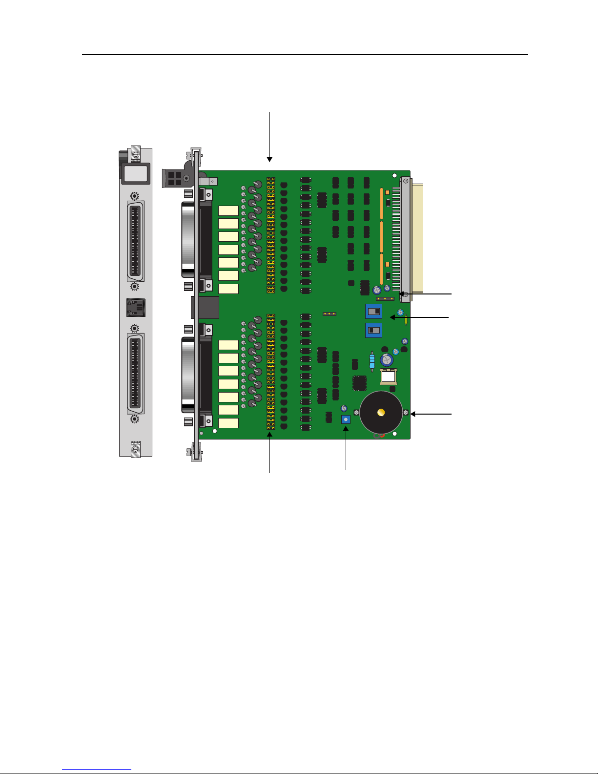
The ALR 28+14 Card has numerous jumper an d other settings, as shown in Figure 1- 3. These
settings are discussed in the following paragraphs.
1-4
Alarm Cards
Page 15
Alarm Cards Alarm Card Descriptions
Alarm Sensor Jumpers for Connector J4
ALR
28+14
P
2
US/Euro
P
3
Jumper
Voltage
Control
Switches
P
1
Onboard
Buzzer
Alarm Sensor Jumpers for
Buzzer Volume Control
Connector J3
Figure 1-3. ALR 28+14 Card Settings
Audible Alarm Buzzer Volume Setting
The ALR 28+14 Card has an on-board buzzer for audible alarms. You can set the buzzer to
activate when a particular sensor detects an incoming alarm. The buzzer volume is set by a
control dial marked VOL, which you can adjust with a small screwdriver.
Alarm Cards
1-5
Page 16

Running Head
Alarm Card Descriptions Alarm Cards
Model No.
U.S./European Voltage Jumpers
You can co nfigur e the ALR 28+14 Ca rd for e ither U.S. or Europea n opera tion b y moving the
jumpers located on JP64. One jumpe r is provid ed for each al arm sensor on the card. Ins erting
a jumper on the left-si de two pi ns select s U.S. volt ages. Inse rting th e jump er on the r ight-si de
two pins selects European voltages. All jumpers should be set to the same position, and this
setting should match t he configuration of t he system chassis for the card to work properl y . The
factory default jumper setting is US.
Voltage Control Switches
Use switches S1 and S2 t o control the volt age suppl ied to ea ch group of active sensors. W hen
either switch is set to SYS, the board supplies +12 and -12 VDC power to the sensor group
associated with th at Amphen ol connec tor. Whe n a swi tch i s set to BAT, t he AL R 28+14 Card
supplies external telco power to the sensors in that group.
You can set the switches individually (i.e., one can be set to SYS and the other to BAT).
However, this will affect all 14 sensors in the respective group.
Switch S1 controls the sensor s on the J3 (lower) connec tor, and swi tch S2 controls the se nsors
on the J4 (upper) connector.
The factory default setting for the voltage control switches is
SYS
.
1-6
Alarm Cards
Page 17
Alarm Cards Alarm Card Descriptions
Alarm Sensor Jumpers
Each sensor is associated with a pair of jumpers that control whether the sensor is powered
from the card (acti ve mode) or an ext ernal device (passive mo de). The pass ive mode provide s
2500V of isolation. Figure 1-4 shows these options.
Current Source
Active Mode
External Device
Alarm Card
Current
Source
Passive Mode
External Device
Alarm Card
Figure 1-4. Active and Passive Alarm Sensor Modes
The jumpers are separated int o two groups of 14 j umper pairs. The upp er group is associ ated
with the sensors on the uppe r amphenol connector (J4), and the lower g roup is associated wit h
the sensors on the lower amphenol connector (J3). The jumper pair sensor assignments are
silk-screened on the card. The jumpers for sensor 1 are indicated as SI1, and the jumpers for
sensor 28 are indicated as SI28. One of these sensor groups is detailed in Figure 1-5.
Alarm Cards
1-7
Page 18
Running Head
Alarm Card Descriptions Alarm Cards
Model No.
Positive (+)
Vol t a ge
Negative (-)
JP3
JP4
PASV
ACTV
Voltage
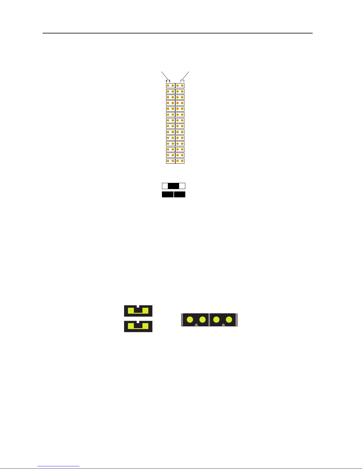
1516 17 1819 22 23 25 26 272820SI 21 24
Figure 1-5. Jumper Pair Assignments
The outside pin of each jumper pair carries a voltage, while the inside pins are passive. The
outside (left) p ins for the jumper pairs in columns JP1 and JP3 c arry positiv e (+) volt ages, and
the outside (ri ght) pins for t he jumper pairs in columns JP2 a nd JP4 carry nega tive (-) volt ages.
The default setting for all jumper pairs is the active mode, a s shown in Figure 1- 6. The sensors
are powered by the ALR 28+14 Card. This setting provides surge protection for the sensors.
Earlier V ersion Later V ersion
Figure 1-6. Jumper Installation for Active Mode
To set the jumper pair to the passive mode, remove both jumpers and then place a single
jumper across the pair , as sh own in Figure 1-7. This provides full isolati on (to 2500V) for the
sensor .
1-8
Alarm Cards
Page 19

Alarm Cards Alarm Card Descriptions
Earlier V ersion Later V ersion
Figure 1-7. Jumper Installation for Passive Mode
The jumper pairs t h at co rrespond to each s ens or are numbered accordi ngly. For example, the
jumper pairs for se nsor 1 2 are in ro w SI12 o f the lower ju mper gr oup (co lumns J P1 a nd JP2) .
Similarly, the jumper pairs that correspond to sensor 25 are in row SI25 of the upper jumper
group (columns JP3 and JP4).
Power Failure Notification
If a system power failur e occurs, swit ch 1 can act as a fai l-safe switch to activate a de vice that
notifies an operator. For th is to occ ur, you must install a j umper on jumpe r pair JP63 near t he
center of the card. The contact for switch 1 will close if the system loses power, establishing
a circuit that can be used to power an external warning device. The current source must be
provided by the external device.
1.2.3.2 Installing the Alarm Card
The Alarm card can be installed in any user card slot. These slots are U1 to U8 on the
two-sided chassis and front-loading chassis with power supplies on top, and P1 to P4 or W1
to W4 on the front-loading chassis with power supplies on the side.
Alarm Cards
1-9
Page 20
Running Head
Alarm Card User Screens and Settings Alarm Cards
Model No.
1.3 Alarm Card User Screens and Settings
1.3.1 Alarm Filter Screen Sensor Setting
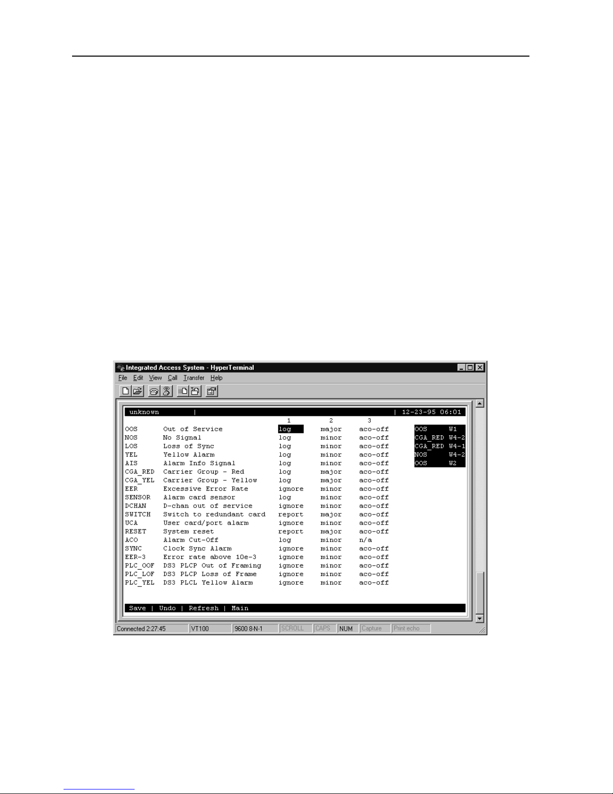
First, make sure the master setting for all alarm senso rs is set properly as the SENSOR vari able
in the Alarm F ilter Screen. To set this variable, first select
Screen, then choose
In this menu, use the arrow keys to highlight the first column of the SENSOR line. Pressing
<Enter> displays the optio ns
highest-level option for all alarm card sensors. If this variable is set to
conditions on the alarm card will be ignored
report
.
Filters
. This will display a list of alarm filters, as shown in Figure 1-8.
ignore, log
, and
report
, even if you set them up individually to
Alarms
. The option chosen here will act as the
from the System Main
,
ignore
any alarm
log
or
Likewise, if you set this variable t o
other than
SENSOR variable be set to
will be logged but not rep orted. For this reason, it is cru cial that the
ignore
report
, all sensors on the Alarm card that are set to anything
log
(see Figure 1-8).
1-10
Figure 1-8. Alarm Filter Screen
Alarm Cards
Page 21
Alarm Cards Alarm Card User Screens and Settings
1.3.2 ALR 4+4 and ALR 4+3PF Card Main Screens
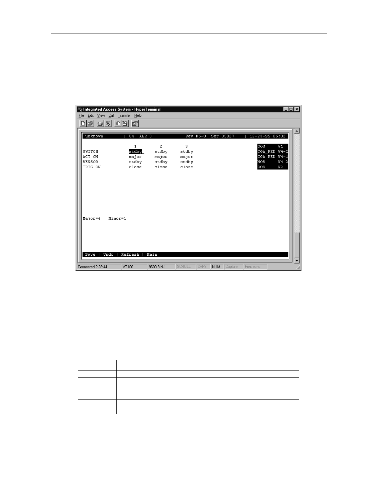
Figure 1-9 shows the ALR 4+4 and ALR 4+3PF Card Main Screen. To go to this screen,
highlight the Alarm card in the System Main Screen and press <Enter>.
Alarm Cards
Figure 1-9. ALR 4+4 and ALR 4+3PF Card Main Screen
The bottom highligh ted line of the s creen shows seve ral actions that you can perform from this
screen. To perform an action, simply press the uppercase letter on your keyboard that
corresponds to the d esire d ac tion. Table 1-1 lists these actions, and Tab le 1-2 s ummarize s th e
card configurat ion option settings and default values. Each paramete r is also described i n t h e
following paragraphs.
Table 1-1. ALR 4+4 and ALR 4+3PF Card Main Screen Actions
Action Function
Save Saves changes to settings.
Undo Returns all settings to the last saved state.
Refresh Updates certain time-related information fields that are not automatically
updated on screen (i.e., alarm data).
Main Returns to the System Main Screen. If changes are made to settings and
not saved, you will be prompted to save or los e changes.
1-11
Page 22

Running Head
Alarm Card User Screens and Settings Alarm Cards
Model No.
Table 1-2. ALR 4+4 and ALR 4+3PF Card Option Settings and Defaults
Parameter User Options Default
SWITCH stdby actv stdby
ACT ON minor major any minor
SENSOR stdby actv stdby
TRIG ON close open close
SWITCH
The Switch setting indicates that the outbound alarm switch is
actv
(on) or
stdby
(off).
ACT ON
The Act On parameter defines the type of system alarm that will cause the switch to trigger.
Program each alarm s witch to trigger on
and critical) alarms, or
alarm message.
any
(information and minor) alarms,
minor
major
(major
SENSOR
The Sensor setting indicates the inbound alarm sensor is
actv
(on) or
stdby
(off).
TRIG ON
The Trigge r On pa rame ter def i nes if the sensor should report an external alarm up on se nsi ng
the opening (
) or the closure (
open
) of the C-form contact to which it is connected.
close
MAJOR =
The Major = accumulation register shows the current number of reported alarms designated
as Major or Critical.
MINOR =
The Minor = accumulation register shows the current number of reported alarms designated
as Minor or Informational.
1-12
Alarm Cards
Page 23
Alarm Cards Alarm Card User Screens and Settings
1.3.3 ALR 28+14 Card Screens and Settings
1.3.4 Ala rm Sensor Screen
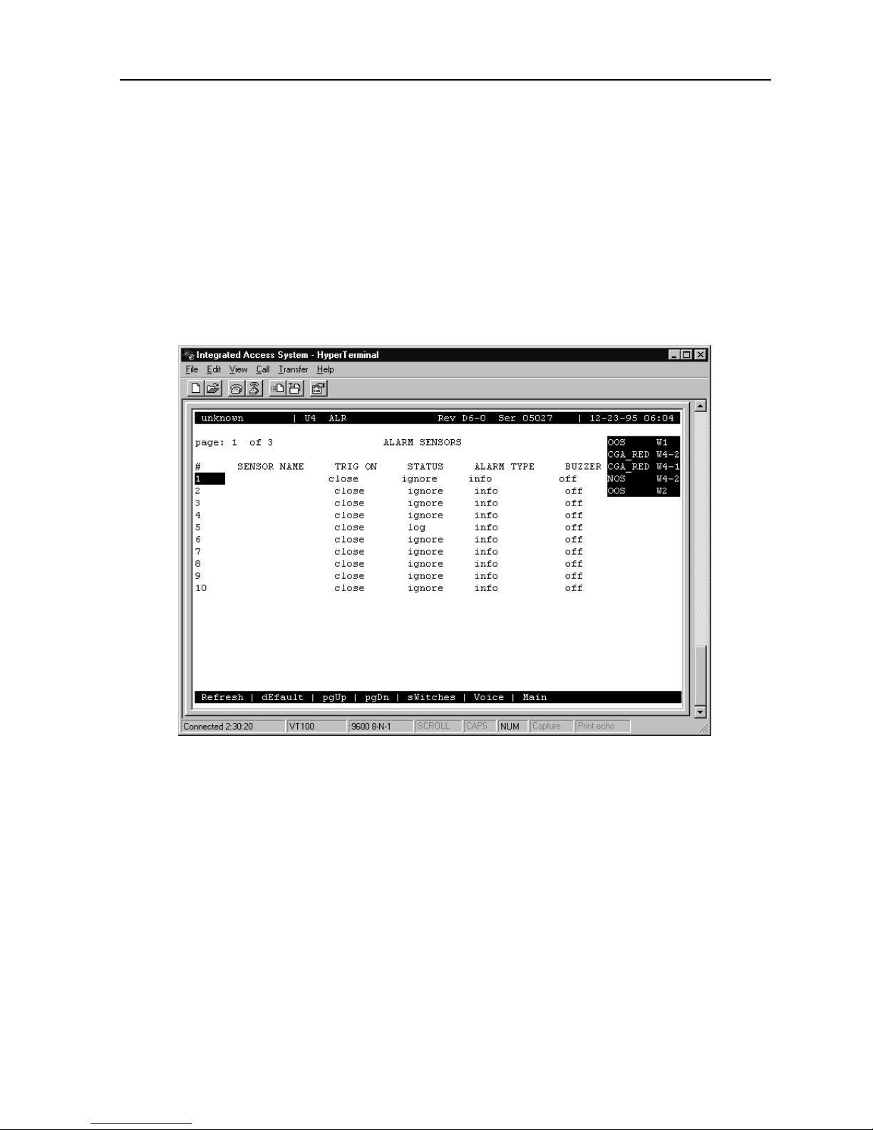
Figure 1-10 shows the first (p age 1) of thr ee Alarm Sen sors Scr een for the ALR 28+14 Car d.
These are the main screens for that card. The first two screens each list 10 sensors, and the
third screen similarly lists 8 sensors. You must give each sensor a name that corresponds to
the incoming alarm, then set each variable for every sensor as described in this section.
Figure 1-10. ALR 28+14 Alarm Sensor Screen
The bottom highligh ted line of the s creen shows seve ral actions that you can perform from this
screen. To perform an action, simply press the uppercase letter on your keyboard that
corresponds to the desired action. For example, to go to the next screen page, type u (
command). Table 1-3 lists these actions, and Table 1-4 lists the configuration option settings
and default values. These parameters are described in the following paragraphs.
Alarm Cards
pgUp
1-13
Page 24

Running Head
Alarm Card User Screens and Settings Alarm Cards
Model No.
Table 1-3. ALR 28+14 Alarm Sensor Screen Actions
Action Function
Refresh Redraws the screen.
dEfault Returns all settings to the d e fau lt state.
pgUp Returns to the previous screen page.
pgDn Goes to the next screen page.
sWitches Displays the Alarm Switch Screen.
Voice Displays the Voice Screen.
Main Returns to the System Main Screen. If changes are made to settings and not
saved, you will be prompted to save or lose change s.
Table 1-4. ALR 28+14 Alarm Sensor Option Settings and Defaults
Parameter User Options Default
# [Alarm Sensor number 1-28] fixed
SENSOR NAME [user-input sensor name] blank
TRIG ON close open close
STATUS ignore log report ignore
ALARM TYPE info minor major crit minor
BUZZER off on off
SENSOR NAME
A user input field of up to six (6) characters to identify the specific alarm. Note that the sensor
name is a local identifier, and is not transmitted with alarm conditions.
TRIG ON
The Trigge r On pa rame ter def i nes if the sensor should report an external alarm up on se nsi ng
the opening (
value is
close
) or the closure (
open
.
) of the contact to which it is connected. The default
close
STATUS
This value indicates what acti on should be taken in the event of an alar m for each individual
sensor. This variable ma y be set to
Reported alarms are also logged by the system. The default value is
the alarm in the ala rm r egi st er, or to
log
ignore
report
.
the alarm.
1-14
Alarm Cards
Page 25
Alarm Cards Alarm Card User Screens and Settings
ALARM TYPE
This user-definable parameter indicates the severity of the incoming alarm. The options are
info, minor, major
, and
. The default value is
crit
minor
.
BUZZER
This variable indicates whether the on-board buzzer should be activated when the sensor
indicates an alarm. The default value is
off
.
1.3.5 Alarm Switch Screen
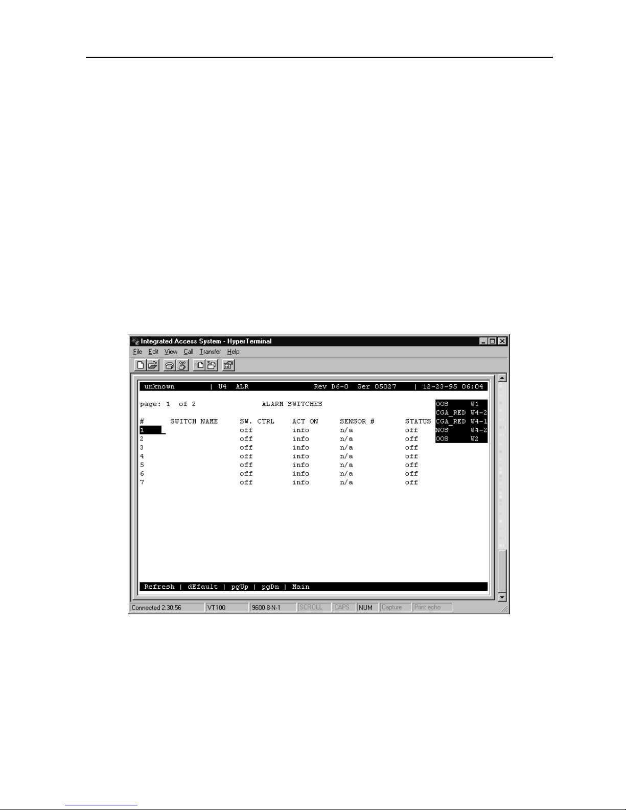
Figure 1-11 shows the first of two Alarm Switch Screens. Each screen (page) lists seven
switches. To go to this screen, press “w” (
sWitches
command) in the Alarm Sensor Screen.
Figure 1-11. ALR 28+14 Alarm Switch Screen
The bottom highligh ted line of the s creen shows seve ral actions that you can perform from this
screen. To perform an action, simply press the uppercase letter on your keyboard that
corresponds to the d esired action . For example, to go to the next scr een page, press “u” (
command). Table 1- 5 lis ts t hese a ctions, a nd Table lists the configuration op tion s etti ngs an d
defaults for the alarm switches. These parameters are described in the following paragraphs.
Alarm Cards
pgUp
1-15
Page 26

Running Head
Alarm Card User Screens and Settings Alarm Cards
Model No.
Table 1-5. ALR 28+14 Alarm Switch Screen Actions
Action Function
Refresh Updates certain time-related information fields that are not automatically
updated.
dEfault Returns all settings to the d e fau lt states.
pgUp Returns to the previous page.
pgDn Goes to the next page.
Main Returns to the Alarm Sensor Screen.
Table 1-6. ALR 28+14 Alarm Switch Option Settings and Defaults
Parameter User Options Notes Default
# Alarm Switch number 1 to 14 fixed
SWITCH Name User-defined switch name blank
SW. CTRL off on act_on act_on
ACT ON info minor major crit sensor major
SENSOR # n/a 1 to 28 1 n/a
STATUS off on displayed
Notes:
1. Sensor numbers are as si gnab le onl y if th e ACT ON par amet er is set to sen sor numbe r
to 28. The default setting is 1.
1
SWITCH NAME
A user-defined field up to six characters identifies the specific switch. Note that the switch
name is a local identifier; it is not transmitted with alarm conditions.
SW. CTRL
This variable indicates the initial state of the switch. The possibilities are
unconditio nally turns the switch off), on (which unconditionally turns the switch on) or
act_on
(which relies on the state of the switch). The default value is
off
As mentioned previously, 12 of the switches are Form C (which may be either open or cl osed),
one is Form A (always open), and one is Form B (always closed).
In the even t of system power failure, switch 1 can be use d as a fail-safe switch to activ ate a
device that notifies the user. In order for this to occur, a jumper must be set on jumper pair
JP63. located towards the center of the car d. The contact for switch 1 will close if the sy st em
loses power, establishing a ci rcu it tha t c an be use d to power an external warni ng device. The
current source must be provided by the external device.
.
(which
off
1-16
Alarm Cards
Page 27

Alarm Cards Alarm Card User Screens and Settings
ACT ON
This parameter defines the condition that will cause the switch to trigger. You can program
each alarm switch to trigger o n
trigger can also be assigned to a parti cular
you to indicate the nu mber of the senso r that will tri gger the alarm. Th e default value i s
info, minor, major
sensor
SENSOR #
, or
. When
alarms. Alternatively, the switch
crit
is selected, SENSOR # allows
sensor
major
.
When the ACT ON field is set to
number of the sensor that will trigger the switch. The default value is
STATUS
This is a display-only field; you cannot edit it.
1.3.6 Voice Screen
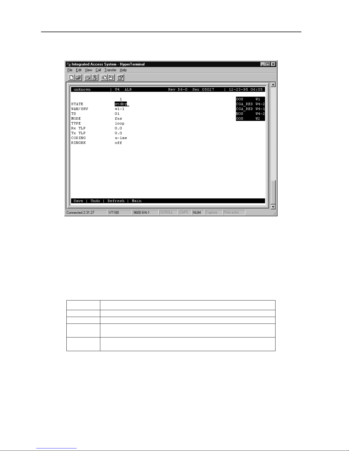
An RJ-11 FXS voice port is located on the ALR 28+14 Card between the two Amphenol
connectors. The i nitial Voice Screen fo r this port is sh own in Figure 1-12. To go to this screen,
press “v” (
command) in the Alarm Sensor Screen.
Voice
, you can enter a value from 1 to 28, indicating the
sensor
.
n/a
Alarm Cards
1-17
Page 28
Running Head
Alarm Card User Screens and Settings Alarm Cards
Model No.
Figure 1-12. ALR 28+14 Voice Screen
The bottom highlighted l ine of the screen sh ows several acti ons that you can perfo rm from the
Voice Screen. To perform an action, simply press the uppercase letter on your keyboard that
corresponds to the d esire d ac tion. Table 1-7 lists these actions, and Tab le 1-8 s ummarize s th e
configuration option settings and default values. These parameters are described in the
following paragraphs.
Table 1-7. ALR 28+14 Voice Screen Actions
Action Function
Save Saves changes to settings.
Undo Returns all settings to the last saved state.
Refresh Updates certain time-related information fields that are not automatically
updated on the screen (e.g., alarm data).
Main Returns to the Alarm Sensor Screen. If changes are made to settings and no t
saved, you will be prompted to save or lose change s.
1-18
Alarm Cards
Page 29

Alarm Cards Alarm Card User Screens and Settings
Table 1-8. ALR 28+14 Voice Option Settings and Defaults
Parameter User Options Default
STATE stdby actv stdby
WAN/SRV none w1-1 through w4-2 none
TS 1 to 24 1 to 31 n/a
MODE fxs plar fxs
TYPE loop d3-m1 d4-m1 d3-m2 d4-m2 d3-m3
d4-m3
RX tlp -10.0 to +2.0 -5.0
TX tlp -10.0 to +5.0 2.0
coding u-law a-inv a-law u-law
ringbk off on off
ST ATE
The State setting determines whether th e port is active or inactive. An inactive port does not
occupy a time slot on a WAN link. Set the State setting to
not using or have not yet configur ed. Set it to
default value is
stdby
.
(active) for ports that are ready for use. The
actv
stdby
loop
(standby) for ports you are
WAN/SRV
The WAN setting identifies the WAN link assigned to this port. The default value is
none
.
TS
The TS setting identifies t he time slo t on the WAN link to which this port is assigned. Values
range from 1 to
links that are programmed for
refer to your cross-connect map for the WAN link. The default value is
System Configuration and Operation
for T1 links and 1 to
24
cas
for E1 links. Time slot 16 is not available on E1
31
or
signaling. For a display of the available time slots,
ccs
. See Chapter 4,
n/a
for more information regarding cross-connect maps.
MODE
The Mode setting sh ould be determined by the type of equi pment to which you are connecting
the port. All options use two- wire balanced connections . The
option allows you to connect a telephone to the system.
The
(private line automatic ringdown) option provides point-to-point unswitched
plar
connections between two telephone sets. This configuration is usually not attached to an
exchange or switch; rather, it provides a “hot line” between two locations.
(Foreign Exchange - Statio n)
fxs
Alarm Cards
1-19
Page 30

Running Head
Alarm Card User Screens and Settings Alarm Cards
Model No.
TYPE
The T ype sett ing matches t he signaling behavior of the FXS equipment and the remote s witch.
The
only available when the MODE settin g is
are
(Loop-start) option, which is used with POTS stations and simple PBX trunks, is
loop
d3-m1, d4-m1, d3-m2, d4-m2, d3-m3
. If the MODE s etting is
fxs
, and
d4-m3
.
, the TYPE options
plar
CAUTION!
Before activating thi s port, verify the behavior expected by both the stat ion and remote central
office equipment, and make sure the system is properly configured.
Rx TL
The Receive Transmission Level Point setting controls the amount of gain or attenuation
added to signals after they are decoded to analog signals. To increase the signal level, set the
RX TLP setting to a positive nu mb er (i. e., t he l arger the number, the more gain is adde d) . To
decrease the signal leve l, set the RX TLP setting to a negative number (i.e., the more negative
the number, the more the signal level is decreased). For example, an incoming signal at -5
dBm can be increased to -3 dBm by setting RX TLP to +2 dB. Accept able val ues range fr om
-10.0 dB
to
+2.0 dB
. The default value is -
5.0
.
Tx TLP
The Transmit Transmission Level Point setting controls the amount of gain or attenuation
added to signals aft er they are recei ved from the local a nalog port and befor e they are encod ed
to digital PCM signals. To increase the signal level, set the TX TLP setting to a negative
number (i.e., the more negative the number, the more gain is added). To decrease the signal
level, set the TX TLP settin g to a positive number (i. e., the more positive the number , the more
the signal level i s decr eased) . For ex ample, an in coming s ignal at -5 dBm can be incre ased t o
-2 dBm by setting TX TLP to -3 dB. Acceptabl e value s range f rom
default value is +
2.0
.
-10.0 dB
to
+5.0 dB
. The
CODING
The Coding setting sets the PCM companding method used for a port. In general, in the
T1/North American enviro nment use
(inverted A-law) or
a-inv
coding default is dete rmined by the type of c ard in the WAN port you select. The default value
is
limitations, but should be read as "mu-law.").
(Note: On the syst em screens, "u" i s used in place of "µ" because of ASCII character
u-law
a-law
coding;
coding. In the E1/Int ernat ional enviro nment, use
µ-law
provides greater 1s den sity than
a-inv
a-law
. The
1-20
Alarm Cards
Page 31

Alarm Cards Alarm Card User Screens and Settings
RINGBK
The ringback setting specifies whether a ringback tone is generated by the system and sent
towards the network. This option should be turned on when the network does not provide an
audible ringing tone to the calling party. The default value is
off
.
Alarm Cards
1-21
Page 32

Running Head
Alarm Card Error Messages Alarm Cards
Model No.
1.4 Alarm Card Error Messages
Refer to Appendix B in the System Reference Guide for further information on Error
Messages regarding this car d.
1.5 Alarm Card Troubleshooting
Alarm card problems could indicate a number of possible causes. Typically, a problem is
indicated by the loss of an incoming alarm signal on a sensor port or the lack of a contact
closure/open in response to an internal alarm. Steps designed to isolate the source of the
problem and return the card to normal operation are detailed below. When troubleshooting
Alarm card problems, you should follow this general sequence:
1. Veri fy tha t the US/ EUR jumper i s corr ectly posit ioned on the Alar m card t o match t he
US/EUR jumper on the chassis. Also ve rify that th e voltage level selected is the same on
JP1 and JP2.
2. Verify that the Alarm card sensor filter (SENSOR) is set to either
Alarm Filters Menu. This men u is ac cessed by select ing "Alarms" from the Main Screen
(not the Alarm Card Screen) , and then selecti ng "Filters." Column 1 lists the filter setting
(ignore, log, or report). You can change the filter setting by highlighting the item you
wish to change and pressin g the <Enter> key. Use the arrow keys to highlight a new filter
setting and press the <Enter> key again. If you are satisfied with your selections,
remember to "Save" before exiting the screen. If you make any changes and then attempt
to exit the screen wit hout sa ving, you will be prompted "Ok to l ose chan ges (y/ n)?" You
must select "y" or "n". If you select "y", any changes will be lost and all selections will
revert to the last saved state.
3. On the Alarm card menu, verify that the switch/senso r in question is s et to active (
If set correc tl y a nd the problem is wit h a s w it ch (contact), go to st ep 4. If the prob lem is
with a sensor, go to step 6.
4. Verify that the amphenol cable is connected correctly to the Alarm card. At a
cross-connection point between the Alarm card and the external “scan point”, open the
circuit under test. Conne ct a Volt-Ohmmeter set to read resist ance acros s the Alarm card
contact in question. If no alarm of the type (Major, Minor or Any) that the contact is
programmed to act upon is pre sent, and it is a n ormally open (NO) c ontact, the met er will
read infinite resi stance. I f you a re te sting a normal ly clo sed (NC) contac t, the meter wi ll
read 0 ohms resistance.
log
or
report
in the
).
actv
5. Generate an alarm of the type (Major, Minor or Any) that the contact is programmed
to act upon. The Volt-Ohmmeter should detect a resistance change from 0 to infinite or
infinite to 0, dependi ng on the type of contact ( NO or NC) . If no c hang e i s det ec te d, t he
switch port may be defective.
1-22
Alarm Cards
Page 33

Alarm Cards Alarm Card Troubleshooting
6. Verify the amphenol cable is connected correctly to the Alarm card. At a
cross-connection point between the Alarm card and the external equipment, open the
circuit under test. Connect a short across the Alarm card sensor input in question. A
SENSOR alarm should be reported. If no alarm is reported, the sensor port may be
defective.
If the Alarm card is determined to be faulty, replace it and return the faulty unit for
7.
repair to the location specified by your distributor.
Note:
Refer to the Alarm Card Filters table located in the System Configuration and
Operation Chapter of the System Reference Manual.
Alarm Cards
1-23
Page 34

Running Head
Alarm Card Troubleshooting Alarm Cards
Model No.
1-24
Alarm Cards
 Loading...