

Page 1
Installation and service of this product should be conducted b y a trained
personnel to avoid bodily injury from electric shock or heavy object
Observe ESD (Electrostatic Discharge) practices during integration to avoid
possible damage to the board and / or other components
FlacheSAN2-D5 Quick Guide
Version 1.00 – 2017.09.18
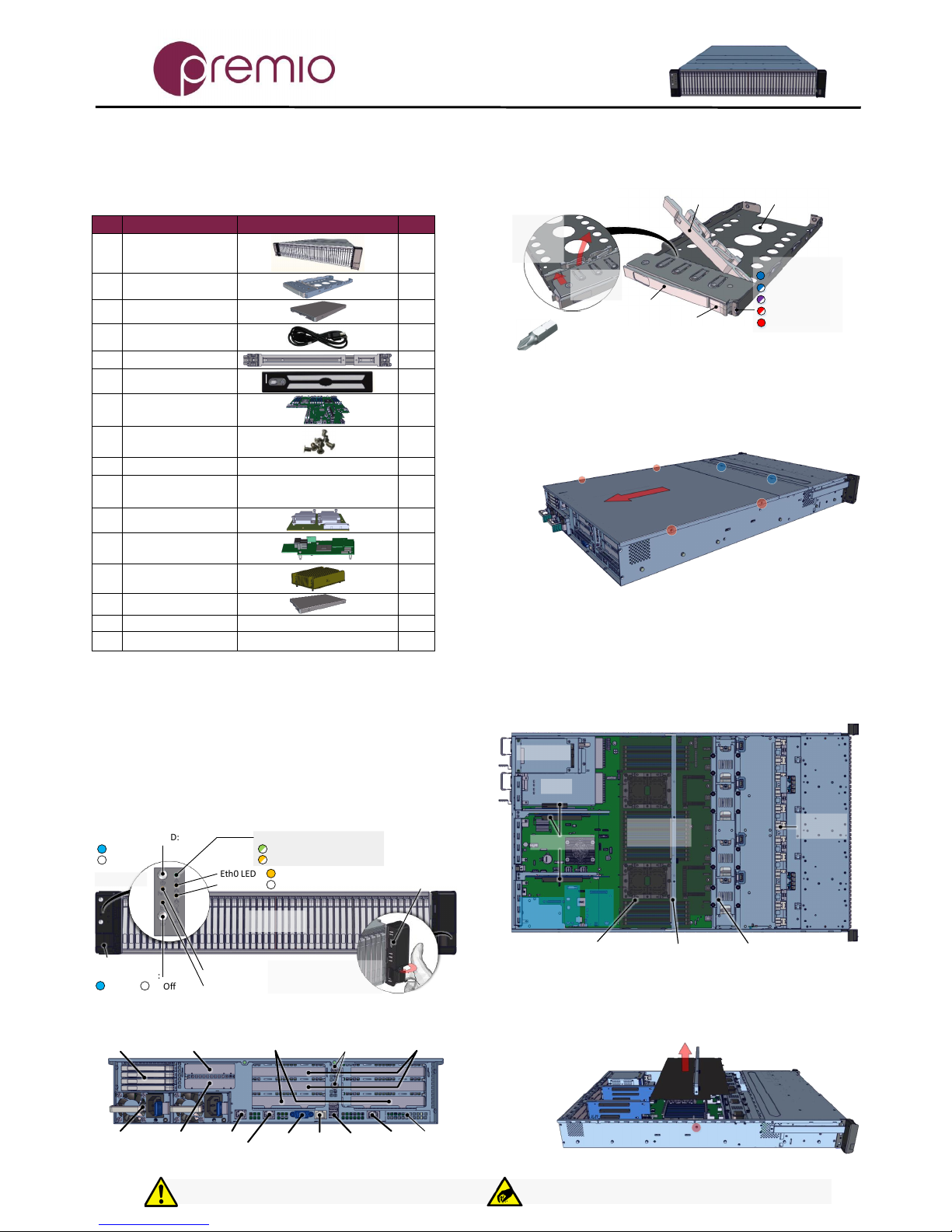
1. Check the content of the box. Please confirm that
your package contains the following:
#
Description
Image / Description
Qty
1
2U 48-Bay Enclosure
1
2
2.5” Drive Trays
48+4
3
Storage SSD (opt.)
48
4
Power Cable*
2
5
Rail Kit (optional)
1
6
Bezel (optional)
1
7
Intel S2600WT MB
(preinstalled)
1
8
6#32 IH#1 Screw Set
for MB / Riser*
1 set
9
IO Cards (optional)
1 set
10
SFF 8087-8643 cable
(preinstalled)
Used for IO cards, optionally
installed by order
12
11
IO Module (opt.)
1
12
RAID Module
(optional)
1
13
Heat sink
2
14
OS Disk (optional)
1-4
15
This quick guide
1
16
Packaging
1 set
* Inside the accessories box. If any items are missing, please contact
your authorized reseller or sales representative
2. Get familiar with the unit.
FlacheSAN2-D5 is a 48x 2.5” 7mm SSD based storage server in
a 2U space, supporting dual Skylake processors powered by
Intel S2600WF motherboard, 6x rear Gen3 x8 FH PCIe cards,
2x LP PCIe cards, and 4-Bay 2.5” canister.
Front view of the unit
Power Button / LED:
System Status LED:
Eth0 LED:
Eth1 LED
USB Port
(Blink) System Healthy
System On
System Off
Link UP /Act
Link Down
Front Panel
ID Button / LED:
Ear Handle
NMI Button
Reset Button
ID On
ID Off
Turn the ear handle
inwards and use the index
finger to pull the unit
48x 2.5"
Drive Bay
(Blink) System Degraded
Rear view of the unit
4x 2.5" Disk
Bay for OS
PSU
LP PCIe Slot
Gen2 x4, x8 mech
LP PCIe Slot
Gen3 x8, x8 mech
FH FL PCIe Slots
Gen3 x8, x16 mech
FH HL PCIe Slots
Gen3 x8, x8 mech
NIC 1
NIC 2
VGA
Port
RJ45
Serial
USB 3.0
Ports
IPMI
Port
IOM
Slot
Expander
Serial Ports
Drive Tray
2.5" 7mm
HDD / SSD
Tray
Drive Lock
(unlocked position)
Tray Latch
Tray Handle
Drive Status LED:
(Solid) Drive Online
To unlock the drive lock:
1. Push the
drive lock
latch
inwards
2. Then pull
it upwards
(Blink) Drive Activity
(Fast Blink) Drive Locate
(Slow Blink) Rebuild
(Solid) Drive Fail
Tool-less drive tray is best used for SSDs.
It is recommended to apply M3 screws when installing HDDs
3. Remove the top cover by removing the 4 screws
on the sides of the unit. Remove additional screws (blue
circles) to open the middle top cover (for fan module access).
Slide the covers towards the back of the unit.
4. Inspect the internal components of the chassis.
FlacheSAN2-D5 system by default comes with Intel S2600WF
Skylake motherboard, an air duct, fan modules, backplanes,
IO cards for 48x SSDs with internal mini-SAS cables. Upon
request, optional items such as ROC Module, OS disk, BBU can
be provided. Note the locations of each component.
Backplane
x4
Rear 4-Bay
PSU
Fan Module x4
Motherboard
S2600WF
Air Duct IO Card Support Bar
Riser Card x3
OCP
Module
SAS
Mod
30mm M.2
5. Remove air duct assembly from the chassis.
Remove two screws from the sides of the unit (red circle) and
pull the air duct / IO card support bar assembly up.
Thank you for your purchase of FlacheSAN2-D5, a 2U 48-Bay Skylake DP Storage Server!
Page 2
FlacheSAN2-D5 Quick Guide
For more information please visit our website at www.premioinc.com
Copyright © 2017, Premio Inc. All rights reserved.
1. Push the tray by the
latch all the way into the
drive bay to ensure a
complete insertion
2. Secure the drive tray
installation by placing the
tray handle to the lock
position
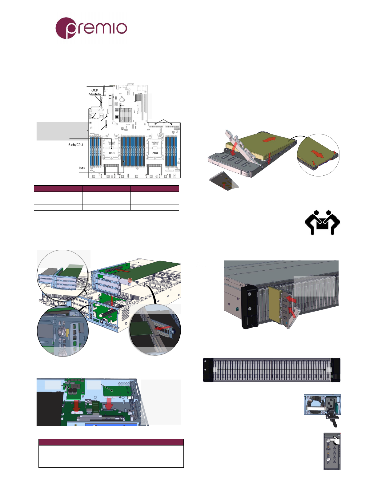
6. Install CPUs, memory (not included) and heat sinks
to their respective slots. Please be aware of each
component’s installation requirements. For details, refer to
S2600WF motherboard TPS. Replace the air duct once
finished.
Two LGA3647-0 (Socket P)
Intel Xeon Scalable (Platinum,
Gold, Silver, Bronze) CPUs
TDP up to 205W
24 DIMMs, 2/ch, 6 ch/CPU
RDIMM, LRDIMM DDR4
1.5TB max (Gold, Plat),
768GB (Silver, Bronze CPU)
2666 MT/s, 1.2V
Start populate on blue slots
first: A,B,C (3 DIMMs);
A,B,D,E (4 DIMMs) and so on
Riser Slot 1
Riser Slot 2
Riser Slot 3
SAS
Module
OCP
Module
PSU Connectors
Riser Card 1 and 2 are Gen3
x24 divided into 3 slots each
Riser Card 3 slots are Gen2
x4 and Gen3 x8
Riser Card 1 is associated
with CPU1
Riser Card 2 and 3 are
associated with CPU2
C624
M.2
M.2
RMM4
Riser Slot 1
Riser Slot 2
Riser Slot 3
Top Slot: CPU 1
Top Slot: CPU 2
Top Slot: CPU 2
Middle Slot: CPU 1
Middle Slot: CPU 2
Bottom Slot: CPU2
Bottom Slot: CPU2
Bottom Slot: CPU2
7. Install IO cards (optional) into PCI-e riser cards.
The unit has two PCIe riser card assemblies. The left assembly
holds five PCIe IO cards for CPU2, the right assembly is for
three PCIe IO cards for CPU1. See below for installation:
2. Remove the IO card slot cover and insert IO card to
PCIe slot on the riser, secure with screw (red circle)
1. Remove the tool-less riser
card assembly by pulling it
upwards and release from hook
(yellow highlight below)
3. Loosen the thumbscrew and
open the card guide bracket
5. Close the card guide bracket
and secure the thumbscrew
4. Replace riser card assembly to motherboard PCIe
slot. Insert the hooks (yellow highlight) to their slots
To install SAS module or OCP module, removal of PCIe riser
card is recommended. See below for instruction:
OCP
Module
SAS
Module
1. Remove the cut off
from the rear panel if
necessary
2. Insert the module to
the connector
3. Secure it with stand
off and screws
Below is the list of compatible SAS and OCP modules:
Compatible SAS Modules
Compatible OCP Modules
RMS3AC160, RMS3CC040, RMS3CC080,
RMS3HC080, RMS3JC080, RMS3VC160,
RMSP3AD160F, RMSP3CD080F,
RMSP3HD080E, RMSP3JD160J
I357T4OCPG1P5
X527DA4OCPG1P5
X557T2OCPG1P5
X527DA2OCPG1P5
8. Put the top cover. Once we are finished with the
internals of the system, close the top of the chassis.
9. Remove drive trays from the enclosure (if no SSDs
are installed already).
10. Install drives into trays. Follow the diagram
closely. SSDs can be provided and installed by request.
1. Slide the drive in with the
IO connector side head first
to the back of the tray
4. Snap in the
hinge back to
lock position
3. Snug the
other end of
the drive into
the tray
2. Make
sure that
the drive
goes
underneath
the hooks
To remove the disk, do the steps in reverse.
Poke from the bottom hole to help release the disk.
11. Place the unit to the rack. Refer to Rail Kit
Installation Guide on how to mount the
enclosure.
Caution: At least two people are required to
lift a fully populated chassis
12. Install the populated drive trays into the
enclosure with the drives properly secured to the hard drive
trays.
13. Drive mapping incrementally goes from left to right
depending on the connection to the IO cards.
481
14. Plug in the power cords to the
AC receptacles on the back of the unit and
secure it with the cable tie.
15. Press the power button on the front
of the unit after connecting a monitor and input
devices, and get ready for software installation.
 Loading...