

Page 1
Installation and service of this product should be conducted b y a trained
personnel to avoid bodily injury from electric shock or heavy object
Observe ESD (Electrostatic Discharge) practices during integration to avoid
possible damage to the board and / or other components
eDrawer4048S Quick Guide
Version 3.70 – 2017.02.07
1. Check the Content of the box. Please confirm that your
package contains the following:
#
Description
Image / Description
Qty
1
eDrawer4048S
Enclosure
1
2
Motherboard
Asrock DP motherboard
1 3 CPU and memory
Intel E5 and DDR4
2 sets
4
Heatsink
2
5
Internal SAS cables
4x SFF8643, 1x SFF8087
1 set
6
2.5” Drive Trays
4
7
Rail Blade
1 set
8
Power Cable*
2
9
Serial Cable*
1
10
Side Handles*
2
* Inside the accessories box. Box may consist of screw sets for rail kit or
drives. If any items are missing, please contact your reseller or sales rep.
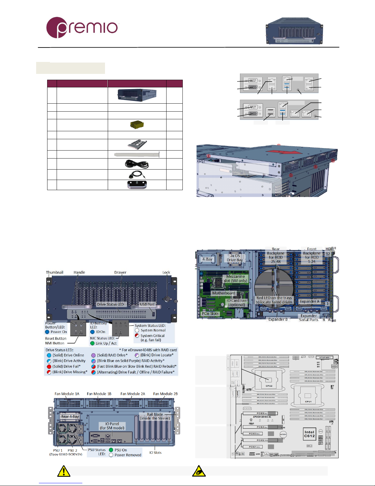
2. Get Familiar with the Unit.
eDrawer4048S is a storage server supporting dual Intel processor and
front drawer 48x 3.5” HDDs, rear 4x 2.5” drive, and 2x 2.5” OS disk in a
4U space. A choice of Asrock motherboard (EP2C612D16C-4L – with 4x
GbE or EP2C612D16SM – with additional PCIe slots) and cabling are
preinstalled. Other motherboard model, IO cards, CPU, and memory can
be preinstalled upon request.
Front view of the unit
Rear view of the unit
Rear IO Panel
ID Button
GLAN1
Asrock EP2C612D16SM
VGA Port
USB2.0
COM Port
IPMI LAN
Asrock EP2C612D16C-4L
GLAN3
USB3.0
GLAN4
IPMI
GLAN1
GLAN2
USB3.0
VGA Port
COM Port
ID ButtonGLAN2
(4L Model)
(SM Model)
3. Remove the Top Cover of the unit as indicated.
1. Remove 5 screws (red circles) securing
the top cover + fan module assembly
2. Remove the top cover + fan module assembly:
Slide the cover assembly towards the rear
Lift the cover assembly off the enclosure
4. Inspect the Inside of the unit. Internal components
comprise of an Asrock motherboard, 1x SFF8087 for rear 2.5” 4-Bay, a
bracket for 2x 2.5” OS disks, 4x SFF8463 SAS cables for 48-Bay and an
optional IO card fan. Front backplane and Fan 1A/2A are routed to
Expander A; rear backplane, rear 4-Bay, and Fan 1B/2B are routed to
Expander B. All fans are controlled by MB. SM model is shown below.
5. Install Motherboard Components (CPU, heatsink,
memory). Below are motherboard diagrams for EP2C612D16C-4L and
EP2C612D16SM. For other motherboards, refer to their respective TPS.
Asrock EP2C612D16C-4L
Two LGA2011 (Socket
R3) processor sockets
Support for one or two
Intel Xeon E5-2600/4600
&v3 series processors
Intel C612 chipset
16 DIMM slots
Quad Channel tech
Supports DDR4
2133/1866/1600
RDIMM and LRDIMM
32GB, 16GB, 8GB,
4GB RDIMM; 64GB,
32GB LRDIMM
PCIE3 (x8), PCIE4
(x16, x8 if PCIE3 is
utilized), PCI6 (x16)
linked to CPU1
PCIE1 (x8), PCIE2
(x16, x8 if PCIE1 is
utilized) link to CPU2
X16 / x8
x8
x16
x8
X16 / x8
Thank you for your purchase of Premio eDrawer4048S Dual Processor Storage Server System!
Page 2
eDrawer4048S Enclosure Quick Guide
For more information please visit our website at www.Premioinc.com
Copyright © 2017,Premio Inc. All rights reserved.
Two LGA2011 (Socket
R3) processor sockets
Support for one or two
Intel Xeon E5-2600/4600
&v3 series processors
Intel C612 chipset
16 DIMM slots
Quad Channel tech
Supports DDR4
2133/1866/1600
RDIMM and
LRDIMM
32GB, 16GB, 8GB,
4GB RDIMM; 64GB,
32GB LRDIMM
All PCIe slots are x8
PCIE1, PCIE2, PCIE6
connected to CPU1
PCIE3, PCIE4, PCI5
connected to CPU2
Asrock EP2C612D16SM
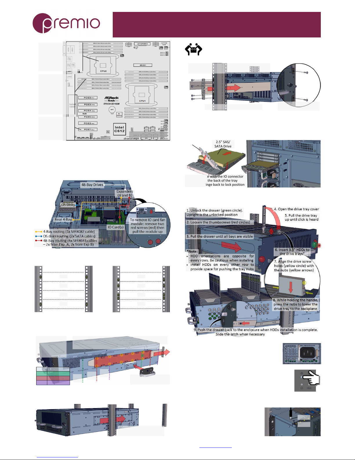
6. Setup Internal Cable Connection. Below is a
recommended connection: OS disks to motherboard on-board SATA
port, rear 4-Bay connected to Expander B then to IO card, 48-Bay disks
to Expanders to HBA/RAID IO card. Install IO cards to PCIe slots using full
height brackets. Close the top cover after finished.
7. Prepare the Rack by installing square nuts:
1U
2U
3U
4U
Front
1U
2U
3U
4U
Rear
8. Prepare the Rails by removing it from the enclosure and
adjust the rail sleeve, as necessary, subject to the depth of your rack:
1. Remove screw
(green circle) to
remove the rail
blade from the
sleeve
2. To adjust rail sleeve, remove the sleeve screws
(yellow circles) and place to desired position (see table).
Pos. Rack Depth
3. Install the handles
to move unit to the lift
*default
Position #2 is the default (sleeve highlighted red).
2*
31" - 35"
Pos.
#2*
Pos.
#1
Pos.
#3
28" - 32"1
3 34" - 38"
9. Install the Unit to the Rack as follows:
1. Using a lift, slide the
unit into the rack half way
Use side handles to help carry the unit to a table or a rack
lift. Side handles are not to be used for rack mounting. At
least two people are recommended for mounting process.
2. Insert the rail blade into the sleeve from the
rear side of the rack. Secure with screws
4. Secure the front side
of the unit with screws
3. Slide the system all the way in
10. Install 2.5” Disks to 4-Bay Drive Trays as
necessary. SSD and HDD may be sold separately. M3 screws are
required if using HDD. Apply screws to bottom side of the drive tray.
Slide in drive with the IO connector
side first to the back of the tray
Snap the hinge back to lock position
Drive Lock
2.5" SAS/
SATA Drive
11. Install 3.5” Drives to the enclosure as illustrated:
12. Plug in the Power Cords to
the AC receptacles on the back of the unit.
13. Press the Power Button on the
front of the unit and wait about 30 seconds for the unit
to be ready.
14. Access the Serial Console (when necessary) by
connecting a serial audio cable to the
one of the console ports. Pull out the
drawer for serial port access. See
picture for detail. Use a terminal
console with baud set 38400, 8, N, 1, N.
Type “help –a” for a list of commands.
Exp. A
Exp. B
 Loading...