

Page 1
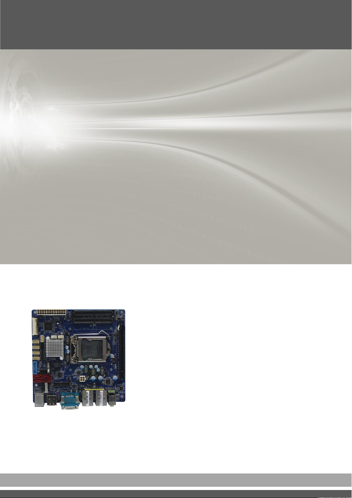
USER’S
MANUAL
CT-XSL01 Series
Mini-ITX Industrial Motherboard
Page 2

CT-XSL01 | User’s Manual
Table of Contents
Prefaces …………………………………………………….……………………………………………. 04
Revision …………………………………………………………………………………………..……………….………..04
Disclaimer ………………………………………………………..…….…….………………………….……………….. 04
Copyright Notice …………………………………….…………………….…………………………………………… 04
Trademarks Acknowledgment …………..………………………………………………………...................04
Environmental Protection Announcement …………………………….………………….……………….. 04
Safety Precautions ………………………………………….……………………………….…………….………….. 05
Technical Support and Assistance …………………………………….…………….…………….…………….06
Conventions Used in this Manual ………………………………………………………………….….………..06
Package Contents …………………………………………………………………………………………….…………07
Ordering Information …………………………………….……………………………………….……….………… 07
Optional Accessory …………...……………………………………..................................................... 07
Chapter 1 Product Introductions ………………………………………………………..… 08
1.1 Overview ……………………….………………………………..………….………………..……….. 09
1.1.1 Key Feature ………….……………………………………….……….…..………..…....... 09
1.2 Hardware Specification ….………………………….....…………….…………..…..………… 10
1.3 Block Diagram ………………………..……………………..…………………………………..…… 11
1.4 Board Dimensions …………………………..…………………………..………..……….………. 12
Chapter 2 Jumper and Connectors ……..…………………..………………………..…. 13
2.1 Switch and Connector Locations ……………………………………..…….…..……..….... 14
2.1.1 Top View ……………………………………………………………………....……………… 14
2.1.2 Bottom View ……………………………………………………………………....……….. 15
2.1.3 Back Panel View …………………………………………………………………………….. 15
2.2 Connector Definition …………………………………………….……….…….………............ 16
2.3 Jumpers Definition ………….……………............................................................. 29
Chapter 3 Features & Interface …………..………………………………………..……… 31
3.1 General Purpose Input & Output (GPIO) ……………………………………………….... 32
3.1.1 GPIO Configuration ………………………………………………………………………... 32
3.2 Watchdog Timer ……………………………….…………………………………..………………... 33
3.2.1 Board Design ……………………………………………………………………….………… 33
3.2.2 Psuedo Code ……………………………………………………………………….……….. 34
Chapter 4 BIOS Setup …………..……………………………………………….……..……… 36
4.1 BIOS Introduction ………………………………………..…….…………………………..…….... 37
4.2 Main Setup ………………………………………..…….…………….…………………………….... 38
4.2.1 System Date …….……………………………………………..……..………….……….... 38
4.2.2 System Time ………..…………………………………………..……….………..………... 38
4.3 Advanced Setup ………………………………………………………..…………………..……….. 39
4.3.1 Trusted Computing ……………….…………..…….………..…..……………..……... 40
4.3.2 ACPI Settings ……………….………..…………………………….………………..……... 41
4.3.3 AMT Configuration ………………….….………..………………..……………..……... 42
4.3.4 PCH FW Configuration ……………….………..………………..……………..……... 42
4.3.5 Super IO Configuration ……………….………..………………..……………..……... 43
4.3.6 Hardware Monitor ……………….………..………………………….……..…..……... 46
4.3.7 Serial Port Console Redirection ……………….………..……………..…..……... 47
4.3.8 CPU Configuration ……………….………..……….…………..………..……..……... 47
4.3.9 Intel TXT Information ……………………….…….……..…..…………………..……...49
4.3.10 SATA Configuration …………….………..………………………..…………..……... 50
2
Page 3

CT-XSL01 | User’s Manual
4.3.11 Network Stack Configuration ……………………………….……………..……...51
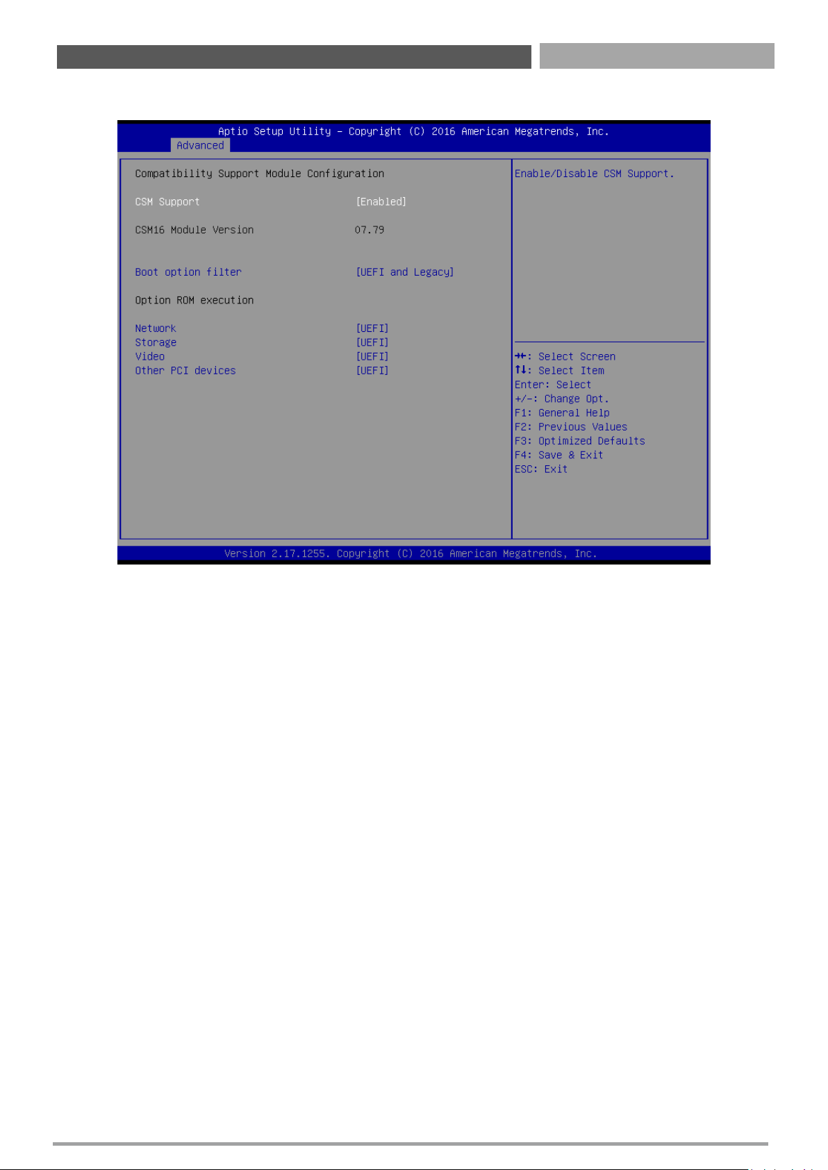
4.3.12 Compatibility Support Module Configuration .……………….……..……... 52
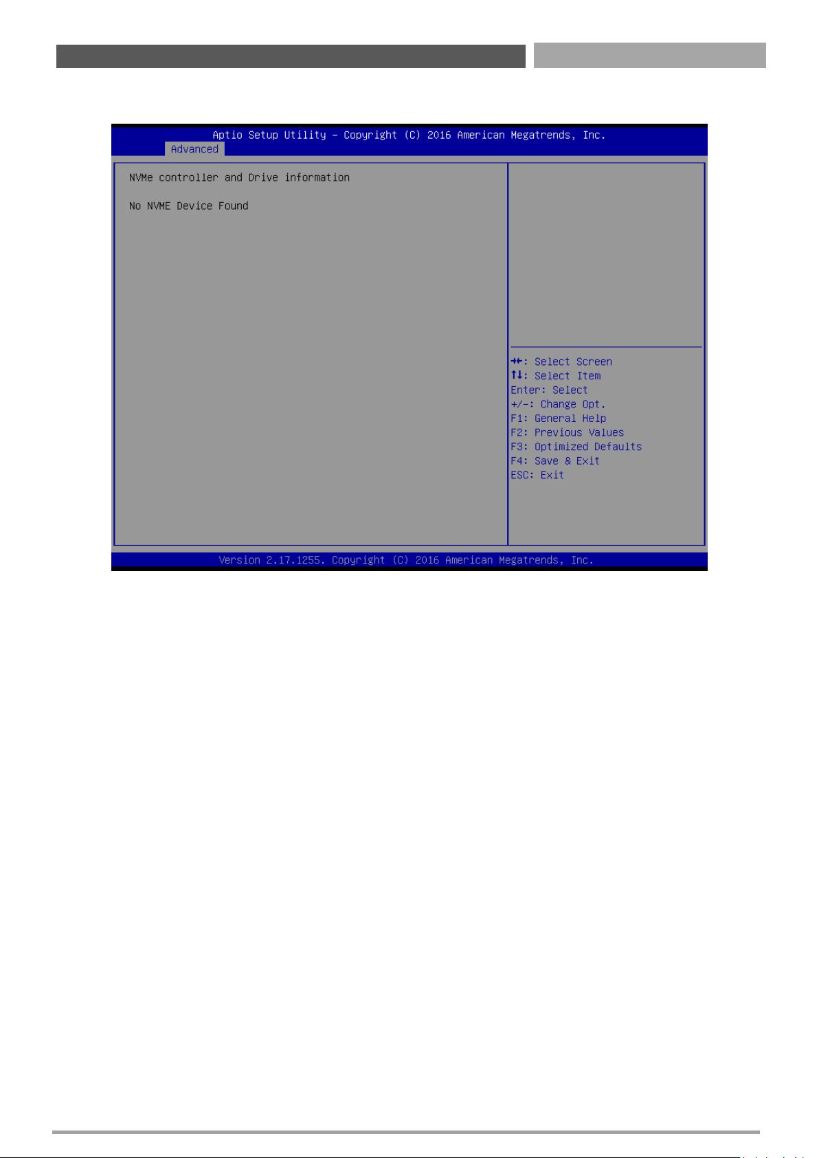
4.3.13 NVMe Configuration …………………………………………………………….……... 53
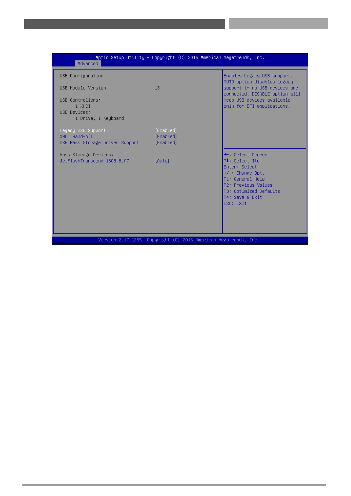
4.3.14 USB Configuration ………………………….……………………………….…………... 54
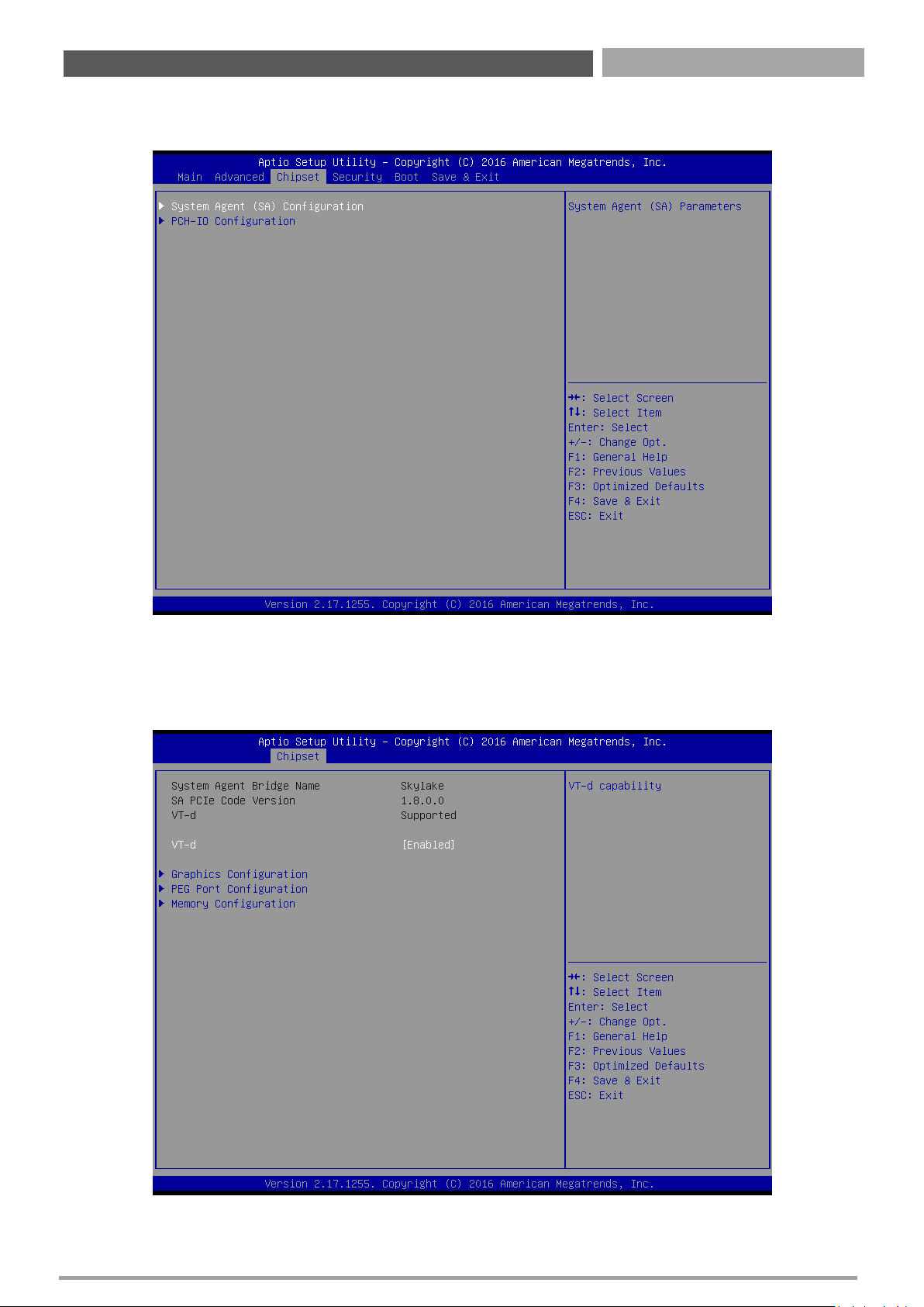
4.4 Chipset …………...……….………………….…..….…..…………..…………………………..….... 55
4.4.1 System Agent Configuration ………………….…………..……………..………….. 55
4.4.2 PCH-IO Configuration ………….…………………………………..…………………….. 59
4.5 Security …………...……….………………….…..….…..………………………..……..…………... 62
4.5.1 Administrator Password …….…………………………………..….………………….. 62
4.5.2 User Password …….……………………………….………………..….………………….. 62
4.6 Boot …………...……….….………………….…..…………………………..………....……………... 63
4.6.1 Setup Prompt Timeout ………………………..…………..……………………………..63
4.6.2 Bootup NumLock State ………………………………………………..………………… 63
4.6.3 Quiet Boot ………………………….……………………….…………………..…...………. 63
4.6.4 Boot mode select [UEFI] …………………………..…………………………………... 63
4.6.5 Boot Option Priorities …………………………..……………………….………….…... 63
4.6.6 UEFI USB Key Drive BBS Priorities ……………………………..…..………….…... 63
4.7 Save & Exit …………...……….….………………………………………..…………..……………... 64
4.7.1 Save Changes and Reset …………………..…………..……………………………….. 64
4.7.2 Discard Changes and Reset ……………………………………..……..……………… 64
4.7.3 Save Changes and Reset …………………………….………………..…..…...………. 64
4.7.4 Restore Defaults …………………………………………..……………..………………... 64
4.7.5 Launch EFI Shell from Filesystem Device ……………………..………………... 64
3
Page 4
CT-XSL01 | User’s Manual
4
Revision
Disclaimer
All specifications and information in this User’s Manual are believed to be accurate and up to date. Premio
Inc. does not guarantee that the contents herein are complete, true, accurate or non-misleading. The
information in this document is subject to change without notice and does not represent a commitment on
the part of Premio Inc.
Premio Inc. disclaims all warranties, express or implied, including, without limitation, those of
merchantability, fitness for a particular purpose with respect to contents of this User’s Manual. Users must
take full responsibility for the application of the product.
Copyright Notice
All rights reserved. No part of this manual may be reproduced or transmitted in any form or by any means,
electronic or mechanical, including photocopying, recording, or information storage and retrieval systems,
without the prior written permission of Premio Inc. Copyright © Premio Inc.
Trademarks Acknowledgment
Intel®, Celeron® and Pentium® are trademarks of Intel Corporation.
Windows® is registered trademark of Microsoft Corporation.
AMI is trademark of American Megatrend Inc.
IBM, XT, AT, PS/2 and Personal System/2 are trademarks of International Business Machines Corporation
All other products and trademarks mentioned in this manual are trademarks of their respective owners.
Environmental Protection Announcement
Do not dispose this electronic device into the trash while discarding. Please recycle to minimize pollution
and ensure environment protection.
Prefaces
Revision
Description
Date
1.0
Manual Released
2016/10/18
Preface
Page 5

CT-XSL01 | User’s Manual
5
Safety Precautions
Before installing and using the equipment, please read the following precautions:
Put this equipment on a reliable surface during installation. Dropping it or letting it fall could
cause damage.
The power outlet shall be installed near the equipment and shall be easily accessible.
Turn off the system power and disconnect the power cord from its source before making any
installation. Be sure both the system and the external devices are turned OFF. Sudden surge
of power could ruin sensitive components. Make sure the equipment is properly grounded.
When the power is connected, never open the equipment. The equipment should be opened
only by qualified service personnel.
Make sure the voltage of the power source is correct before connecting the equipment to the
power outlet.
Disconnect this equipment from the power before cleaning. Use a damp cloth. Do not use
liquid or spray detergents for cleaning.
Avoid the dusty, humidity and temperature extremes.
Do not place heavy objects on the equipment.
If the equipment is not used for long time, disconnect it from the power to avoid being
damaged by transient over-voltage.
The storage temperature shall be above -40°C and below 80°C.
The computer is provided with a battery-powered real-time clock circuit. There is a danger of
explosion if incorrectly replaced. Replace only with the same or equivalent type
recommended by the manufacturer.
If one of the following situation arises, get the equipment checked be service personnel:
• The power cord or plug is damaged.
• Liquid has penetrated into the equipment.
• The equipment has been exposed to moisture.
• The equipment does not work well or it cannot work according the user’s manual.
• The equipment has been dropped and damaged.
• The equipment has obvious signs of breakage.
Preface
Page 6
CT-XSL01 | User’s Manual
6
Technical Support and Assistance
1. Visit the C&T Solution Inc website at www.premioinc.com where you can find the latest information
about the product.
2. Contact your distributor, our technical support team or sales representative for technical support if
you need additional assistance. Please have following information ready before you call:
Model name and serial number
Description of your peripheral attachments
Description of your software (operating system, version, application software, etc.)
A complete description of the problem
The exact wording of any error messages
Conventions Used in this Manual
Preface
This indication alerts operators to an operation that, if not strictly observed,
may result in severe injury.
WARNING
This indication alerts operators to an operation that, if not strictly observed,
may result in safety hazards to personnel or damage to equipment.
CAUTION
This indication provides additional information to complete a task easily.
NOTE
Page 7

CT-XSL01 | User’s Manual
7
Package Contents
Before installation, please ensure all the items listed in the following table are included in the package.
Item
Description
Q’ty
1
CT
-XSL01 Mini-ITX Industrial Motherboard 1
2
I/O Port Bracket
1
3
SATA Cable
1
Preface
Ordering Information
Model No. Product Description
CT-XSL01
Mini-
ITX Industrial Motherboard with LGA 1151 Socket for 6th Gen. Intel®
Core™ i7/i5/i3 Processor, Q170 PCH
Page 8

Chapter 1
Product Introductions
Page 9
CT-XSL01 | User’s Manual
9
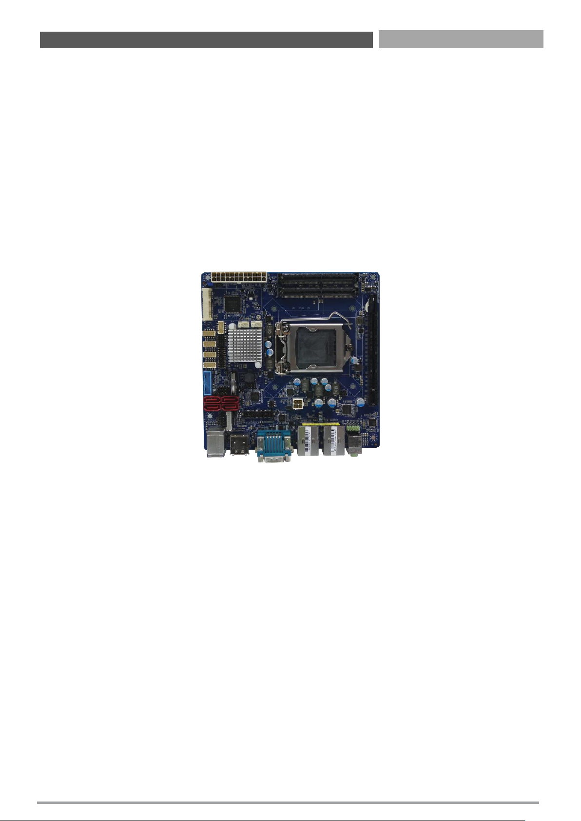
1.1 Overview
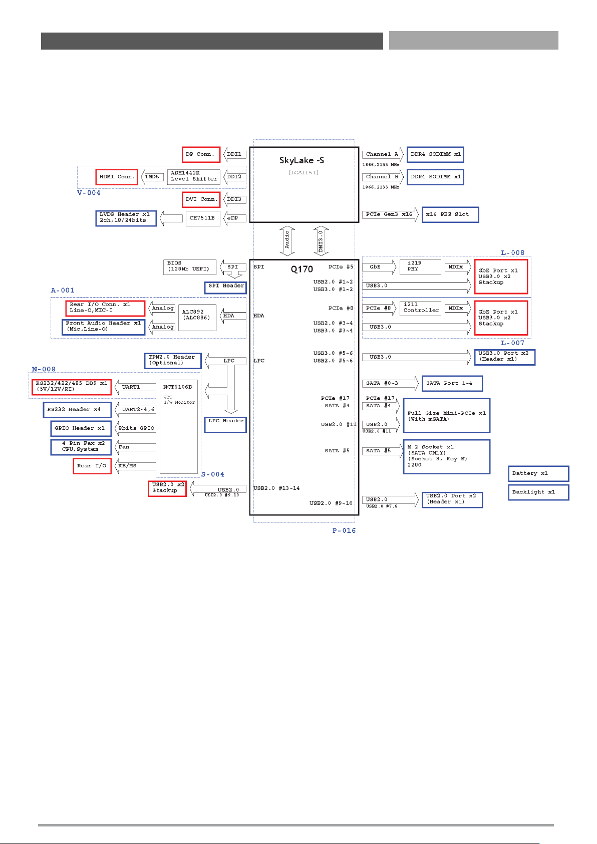
CT-XSL01 is a mini-ITX industrial motherboard with LGA1151 socket to support Intel 6thGeneration
Core i7/i5/i3, Celeron, and Pentium Processor. Two DDR4 SODIMM memory sockets enables a
maximum of 32GB. The Intel 9thGeneration Graphic integrated with the processor supports three
independent displays from the DVI, DisplayPort, HDMI, or LVDS onboard.
The I/O interface of the board gives the users rich connectivity. It supports 2x Gigabit Ethernet,
USB3.0/2.0, COM, GPIO, SATA, mSATA, M.2 for various different applications. The mini PCIe and
PCIex16 slots also enables flexibility and expandability.
Chapter 1: Product Introductions
1.1.1 Key Features
Intel® 6th Gen. Core™ i7 / i5/ i3 Processor (LGA1151) with Q170 PCH
2x DDR4 SO-DIMM support up to 32GB
2x Intel® GbE supporting Wake-on-LAN and PXE
Supports triple displays from DVI / DisplayPort / HDMI / LVDS
Supports 1x PCIe x16, 1x Mini PCIe
Supports 1x mSATA (shared by 1x Mini PCI Express), 1x M.2, and 4x SATA 6.0Gb/s
Supports up to 5x COM port, 6x USB 3.0, 4x USB 2.0
1x 8-bit GPIO (4-in / 4-out)
Support Intel® AMT 11.0
Supports TPM 2.0 (optional)
Page 10

CT-XSL01 | User’s Manual
10
1.2 Hardware Specification
Chapter 1: Product Introductions
System
• Processor: LGA 1151 socket supporting 6th Gen
Intel® Core™ i3/i5/i7 Desktop Processor
- Intel® Core™ i7-6700TE, Quad Core, up to 3.4
GHz
- Intel® Core™ i5-6500TE, Quad Core, up to 3.3
GHz
- Intel® Core™ i3-6100TE, Dual Core, 2.7 GHz
• System Chipset: Intel® Q170 PCH
• LAN Chipset:
- 1x Intel® I219LM GbE PHY
- 1x Intel® I211AT GbE controller
• Audio Codec: Realtek ALC892 HD Audio Codec
• Memory: 2x 260-Pin DDR4 1866/2133MHz SODIMM
• Max. Size: 32GB
• BIOS: AMI uEFI 128MB SPI flash
• Watchdog:
- Software Programmable Supports 1~255 sec.
- System Reset
• TPM: TPM2.0 supported (optional)
• iAMT: Intel® AMT 11.0 supported
Display
• Chipset: Intel® 9th Generation Graphic
• Interface: 1x DVI-D, 1x 2-ch 24-bit LVDS, 1x
DisplayPort, 1x HDMI
• Multiple Display: Triple Display
Storage
• SATA: 4 x SATA 6.0Gb/s
• mSATA: 1x mSATA (shared by 1x Mini PCI Express)
• M.2: 1x M.2 (M-Key, Type: 2280)
Expansion
• Mini PCI Express: 1x Full-size Mini PCIe
• PCI Express: 1x PCIe x16
Rear I/O
• Display: 1x DVI-D, 1x DisplayPort, 1x HDMI
• COM: 1x RS-232/422/485
• USB: 4x USB 3.0, 2x USB 2.0
• LAN: 2x RJ45
• Audio: 1x Line-out, 1x Mic-in
• PS/2: 1x PS/2 KB/MS
Internal I/O
• Display: 1x 2-ch 24-bit LVDS
• COM: 4x RS-232
• USB: 2x USB 3.0, 2x USB 2.0
• SATA: 4 x SATA 6.0Gb/s
• Audio: 1x Front panel audio
• GPIO: 1x 8-bit GPIO (4-in/4-out)
• Others:
- 1x LPC
- 1x Front panel
- 1x CPU fan
- 1x System fan
Operating System
• Windows: Windows 10, Windows 8.1, WES8.1,
Windows 7, WES7
• Linux: Linux kernel 4.X
Power
• Power Connector: 2x12-pin and 2x2-pin power
connector
• Power Input: ATX power
• Management: ACPI 5.0 compliant
Mechanical & Environment
• Form Factor: Mini-ITX
• Dimension: 170mm x 170mm
• Operating Temp.: 0°C ~ 60°C
• Storage Temp.: -40°C ~ 80°C
• Relative humidity: 10% ~ 90% relative humidity,
non-condensing
Page 11
CT-XSL01 | User’s Manual
11
1.3 Block Diagram
Chapter 1: Product Introductions
Page 12

CT-XSL01 | User’s Manual
12
1.4 Board Dimensions
Unit: mm
Chapter 1: Product Introductions
Page 13

Chapter 2
Jumper and Connectors
Page 14
CT-XSL01 | User’s Manual
14
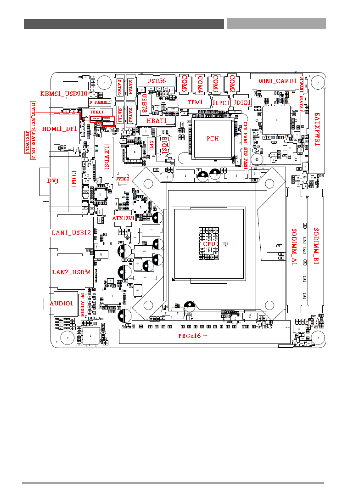
2.1 Switch & Connector Locations
2.1.1 Top View
Chapter 2: Jumper & Connectors
Page 15
CT-XSL01 | User’s Manual
15
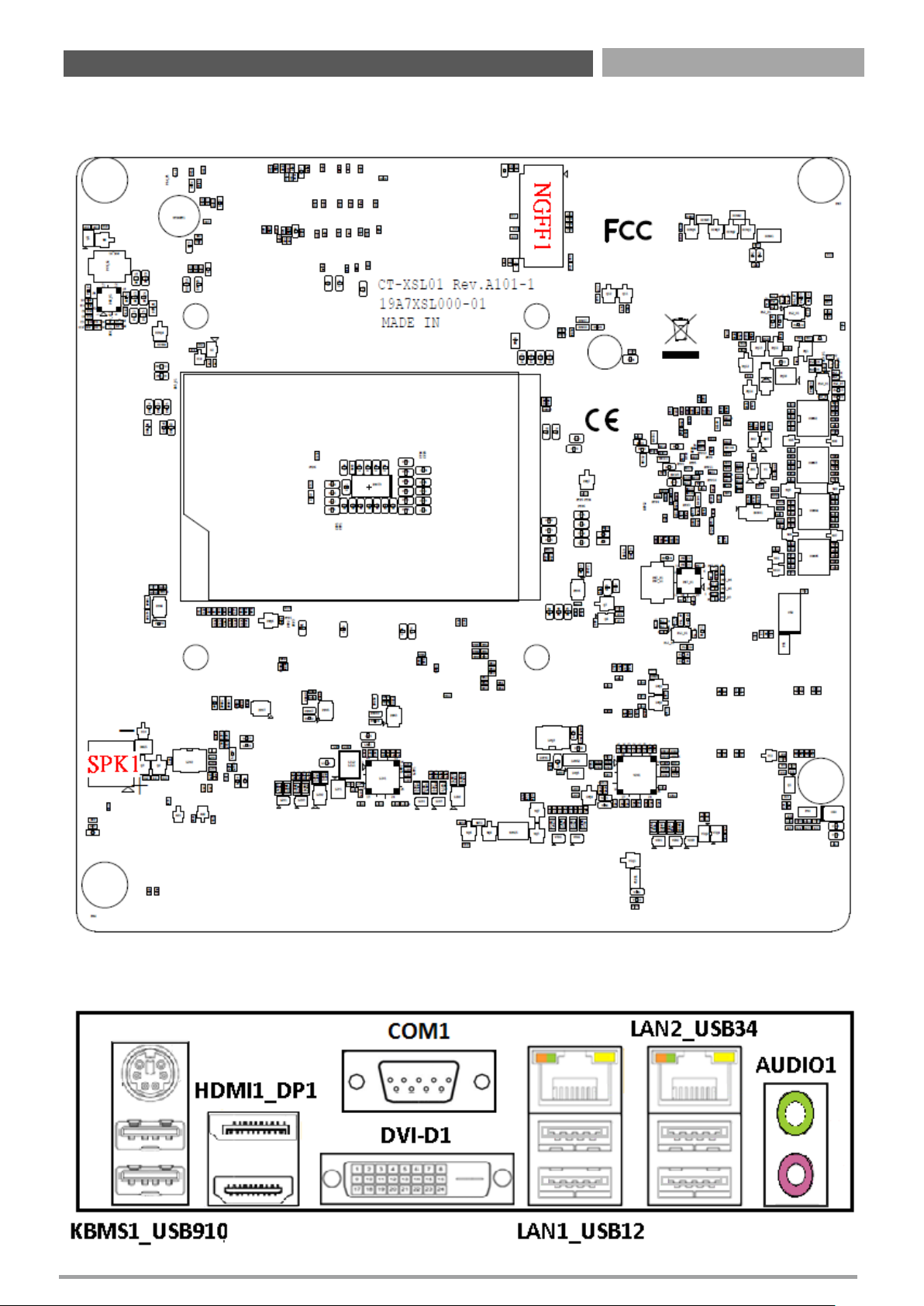
2.1.2 Bottom View
2.1.3 Back Panel View
Chapter 2: Jumper & Connectors
Page 16
CT-XSL01 | User’s Manual
16
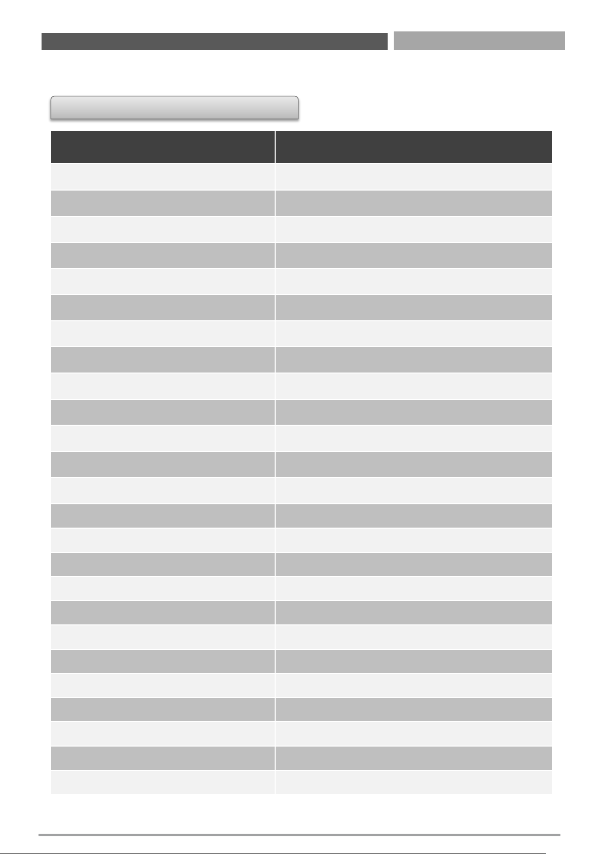
2.2 Connectors Definition
List of Connectors
Connectors Location Definition
KBMS1_USB910
PS/2
and USB2.0 Ports
HDMI1_DP1
HDMI
and DisplayPort Ports
DVI
-D1
DVI
-D Connector
COM1
Serial
Port
LAN1_USB12
LAN1
and USB3.0 Ports
LAN2_USB34
LAN2
and USB3.0 Ports
AUDIO1
Line
-out Jack and Microphone Jack
PCIEX
16_1
PCI
-Express X16 Slot
JLVDS1
LVDS
Connector
JBKL1
Panel
Power Connector
USB
78
Front
Panel USB2.0 Header
SATA
1, SATA2, SATA3, SATA4
SATA
Connector
COM2, COM3, COM4, COM5
Serial
Port Connector
FP_AUDIO1
Front
Panel Audio Header
CPU_FAN
1, SYS_FAN1
FAN
Connector
F_PANEL
1
Front
Panel Header
EATXPWR
1
Main
Power Supply Connector
ATX12V1
Processor
Power Supply Connector
JLPC1
Debug
Header
SPI1
SPI
Header
JDIO
1
GPIO
Connector
TPM
1
TPM
Header
MINI_CARD
1_1
Mini
PCI-Express / mSATA Socket
NGFF
1
M.2
Socket
USB
56
USB3.0
Connector
Chapter 2: Jumper & Connectors
Page 17
CT-XSL01 | User’s Manual
17
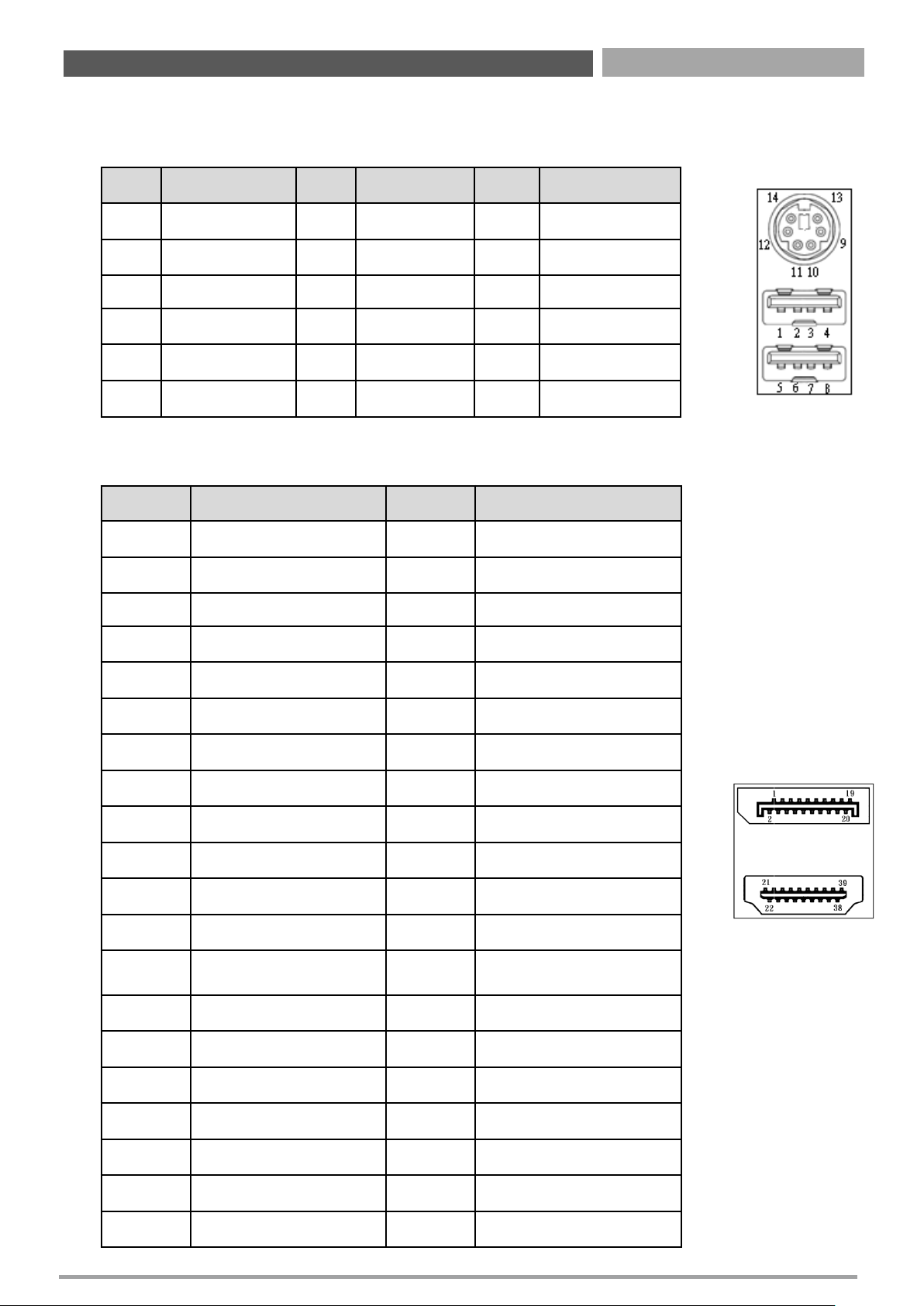
KBMS1_USB910: PS/2 and USB2.0 Ports
Connector Type: 6-pin Mini-DIN and dual USB 2.0 ports
Pin Definition Pin Definition Pin Definition
1 +5V_DUAL 5 +5V_DUAL 9 GND
2 USB2_D10- 6 USB2_D9- 10 KB_DATA
3 USB2_D10+ 7 USB2_D9+ 11 MS_DATA
4 GND 8 GND 12 +5V_DUAL
13 KB_CLK
14 MS_CLK
HDMI1_DP1: HDMI and DisplayPort Ports
Pin Definition Pin Definition
1 DP_DP0 21 HDMI_DP2
2 GND 22 GND
3 DP_DN0 23 HDMI_DN2
4 DP_DP1 24 HDMI_DP1
5 GND 25 GND
6 DP_DN1 26 HDMI_DN1
7 DP_DP2 27 HDMI_DP0
8 GND 28 GND
9 DP_DN2 29 HDMI_DN0
10 DP_DP3 30 HDMI_CKP
11 GND 31 GND
12 DP_DN3 32 HDMI_CKN
13
DP / HDMI Singnal
Switch
33 NC
14 GND 34 NC
15 DP_AUXP 35 HDMI_DDC_CLK
16 GND 36 HDMI_DDC_DATA
17 DP_AUXN 37 GND
18 DP_Hot Plug 38 HDMI_PWR
19 GND 39 HDMI_Hot Plug
20 DP_PWR
Chapter 2: Jumper & Connectors
Page 18
CT-XSL01 | User’s Manual
18
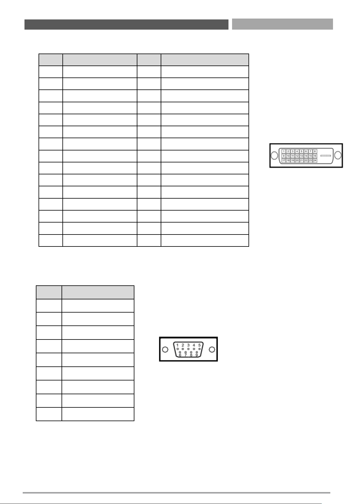
DVI-D1: DVI-D Connector
Pin Definition Pin Definition
1 DVI_TX2- 16 DVI Hot Plug
2 DVI_TX2+ 17 DVI_TX0-
3 GND 18 DVI_TX0+
4 NC 19 GND
5 NC 20 NC
6 DVI_DDC_CLOCK 21 NC
7 DVI_DDC_DATA 22 GND
8 NC 23 DVI_CLK+
9 DVI_TX1- 24 DVI_CLK-
10 DVI_TX1+ C1 NC
11 GND C2 NC
12 NC C3 NC
13 NC C4 NC
14 +5V C5 GND
15 GND
COM1: Serial Port
Connector Type: 9-pin D-Sub
Pin Definition
1 DCD1
2 RXD1
3 TXD1
4 DTR1
5 GND
6 DSR1
7 RTS1
8 CTS1
9 RI1
Chapter 2: Jumper & Connectors
Page 19
CT-XSL01 | User’s Manual
19
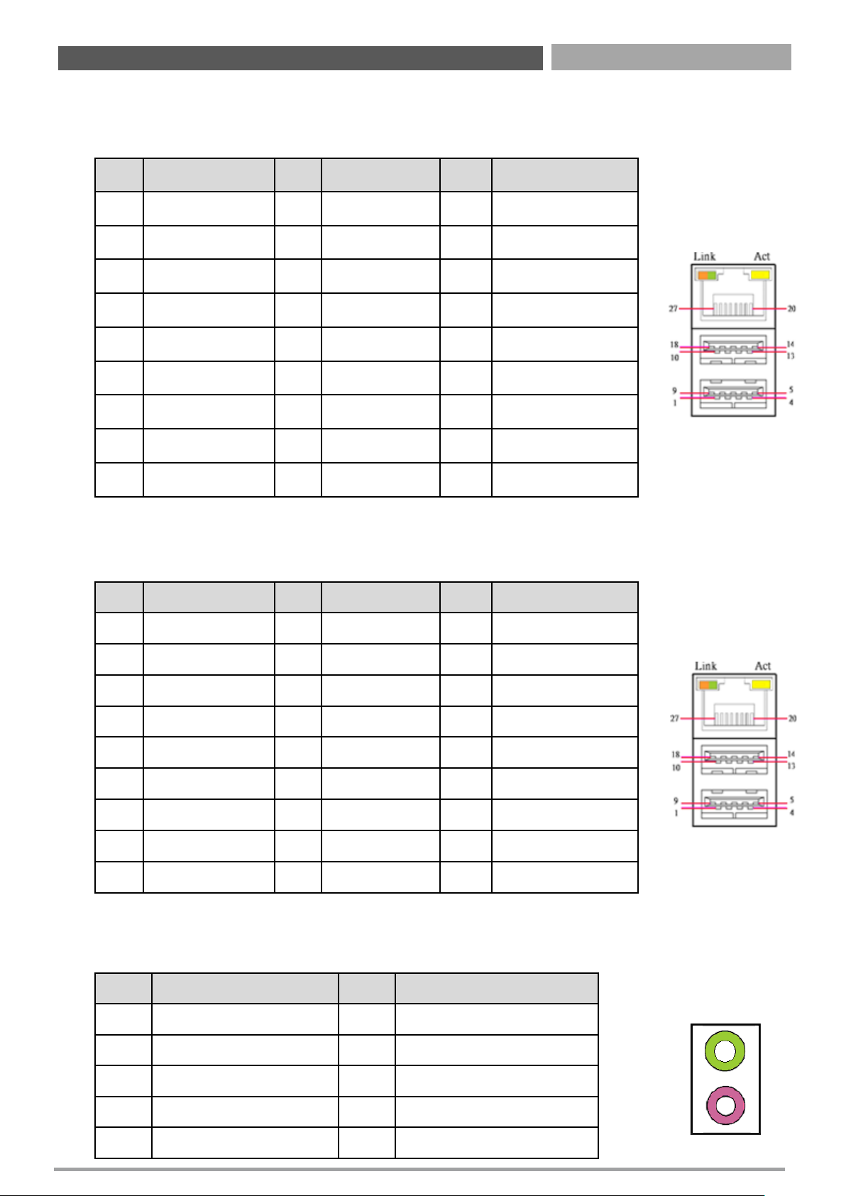
LAN2_USB34: LAN2 and USB3.0 Ports
Connector Type: RJ45 port with LEDs and dual USB3.0 ports
Pin Definition Pin Definition Pin Definition
1 +5V 10 +5V 20 LAN2_MDI0P
2 USB2_D3- 11 USB2_D4- 21 LAN2_MDI0N
3 USB2_D3+ 12 USB2_D4+ 22 LAN2_MDI1P
4 GND 13 GND 23 LAN2_MDI2P
5 USB3_RX3- 14 USB3_RX4- 24 LAN2_MDI2N
6 USB3_RX3+ 15 USB3_RX4+ 25 LAN2_MDI1N
7 GND 16 GND 26 LAN2_MDI3P
8 USB3_TX3- 17 USB3_TX4- 27 LAN2_MDI3N
9 USB3_TX3+ 18 USB3_TX4+
AUDIO1: Line-out Jack (Green) and Microphone Jack (Pink)
Connector Type: 5-pin Phone Jack
Pin Definition Pin Definition
1 GND 22 LINE-OUT_L
2 MIC-IN_L 23 GND
3 GND 24 LINE-OUT_Jack Detect
4 MIC-IN_Jack Detect 25 LINE-OUT_R
5 MIC-IN_R
LAN1_USB12: LAN1 and USB3.0 Ports
Connector Type: RJ45 port with LEDs and dual USB3.0 ports
Pin Definition Pin Definition Pin Definition
1 +5V 10 +5V 20 LAN1_MDI0P
2 USB2_D1- 11 USB2_D2- 21 LAN1_MDI0N
3 USB2_D1+ 12 USB2_D2+ 22 LAN1_MDI1P
4 GND 13 GND 23 LAN1_MDI2P
5 USB3_RX1- 14 USB3_RX2- 24 LAN1_MDI2N
6 USB3_RX1+ 15 USB3_RX2+ 25 LAN1_MDI1N
7 GND 16 GND 26 LAN1_MDI3P
8 USB3_TX1- 17 USB3_TX2- 27 LAN1_MDI3N
9 USB3_TX1+ 18 USB3_TX2+
Chapter 2: Jumper & Connectors
Page 20
CT-XSL01 | User’s Manual
20
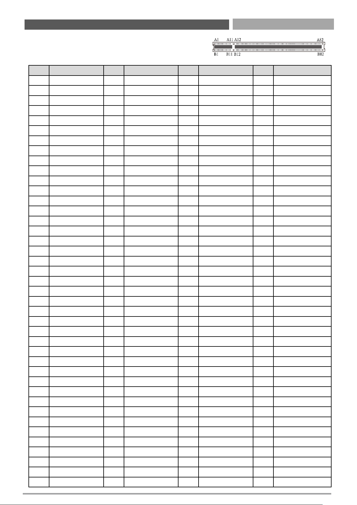
PCIEX16_1: PCI-Express X16 Socket
Connector Type: PCI-Express X16 Slot
Pin Definition Pin Definition Pin Definition Pin Definition
A1
PRSNT#1
A42
GND
B1
+12v
B42
HSOn(6)
A2
+12v
A43
HSIp(6)
B2
+12v
B43
GND
A3
+12v
A44
HSIn(6)
B3
+12v
B44
GND
A4
GND
A45
GND
B4
GND
B45
HSOp(7)
A5
JTAG2
A46
GND
B5
SMCLK
B46
HSOn(7)
A6
JTAG3
A47
HSIp(7)
B6
SMDAT
B47
GND
A7
JTAG4
A48
HSIn(7)
B7
GND
B48
PRSNT#2
A8
JTAG5
A49
GND
B8
+3.3v
B49
GND
A9
+3.3v
A50
RSVD
B9
JTAG1
B50
HSOp(8)
A10
+3.3v
A51
GND
B10
3.3Vaux
B51
HSOn(8)
A11
PWRGD
A52
HSIp(8)
B11
WAKE#
B52
GND
A12
GND
A53
HSIn(8)
B12
RSVD
B53
GND
A13
REFCLK+
A54
GND
B13
GND
B54
HSOp(9)
A14
REFCLK-
A55
GND
B14
HSOp(0)
B55
HSOn(9)
A15
GND
A56
HSIp(9)
B15
HSOn(0)
A56
GND
A16
HSIp(0)
A57
HSIn(9)
B16
GND
B57
GND
A17
HSIn(0)
A58
GND
B17
PRSNT#2
B58
HSOp(10)
A18
GND
A59
GND
B18
GND
B59
HSOn(10)
A19
RSVD
A60
HSIp(10)
B19
HSOp(1)
B60
GND
A20
GND
A61
HSIn(10)
B20
HSOn(1)
B61
GND
A21
HSIp(1)
A62
GND
B21
GND
B62
HSOp(11)
A22
HSIn(1)
A63
GND
B22
GND
B63
HSOn(11)
A23
GND
A64
HSIp(11)
B23
HSOp(2)
B64
GND
A24
GND
A65
HSIn(11)
B24
HSOn(2)
B65
GND
A25
HSIp(2)
A66
GND
B25
GND
B66
HSOp(12)
A26
HSIn(2)
A67
GND
B26
GND
B67
HSOn(12)
A27
GND
A68
HSIp(12)
B27
HSOp(3)
B68
GND
A28
GND
A69
HSIn(12)
B28
HSOn(3)
B69
GND
A29
HSIp(3)
A70
GND
B29
GND
B70
HSOp(13)
A30
HSIn(3)
A71
GND
B30
RSVD
B71
HSOn(13)
A31
GND
A72
HSIp(13)
B31
PRSNT#2
B72
GND
A32
RSVD
A73
HSIn(13)
B32
GND
B73
GND
A33
RSVD
A74
GND
B33
HSOp(4)
B74
HSOp(14)
A34
GND
A75
GND
B34
HSOn(4)
B75
HSOn(14)
A35
HSIp(4)
A76
HSIp(14)
B35
GND
B76
GND
A36
HSIn(4)
A77
HSIn(14)
B36
GND
B77
GND
A37
GND
A78
GND
B37
HSOp(5)
B78
HSOp(15)
A38
GND
A79
GND
B38
HSOn(5)
B79
HSOn(15)
A39
HSIp(5)
A80
HSIp(15)
B39
GND
B80
GND
A40
HSIn(5)
A81
HSIn(15)
B40
GND
B81
PRSNT#2
A41
GND
A82
GND
B41
HSOp(6)
B82
RSVD#2
Chapter 2: Jumper & Connectors
Page 21
CT-XSL01 | User’s Manual
21
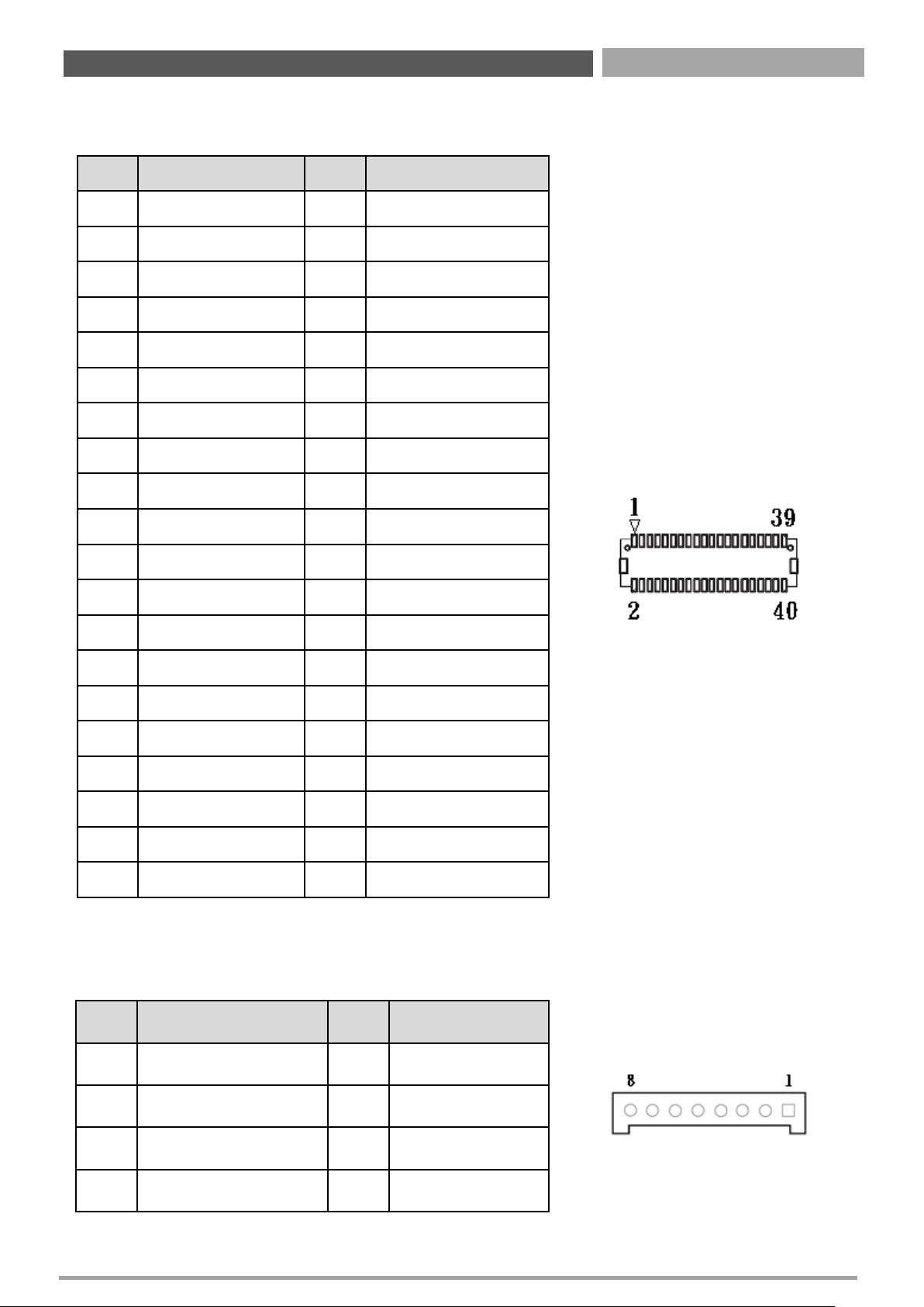
JLVDS1: LVDS Connector
Connector Type: 2x20-pin pitch1.25mm LVDS connector
Pin Definition Pin Definition
1 VDD_LVDS 2 VDD_LVDS
3 GND 4 GND
5 VDD_LVDS 6 VDD_LVDS
7 LVDS_A0- 8 LVDS_B0-
9 LVDS_A0+ 10 LVDS_B0+
11 GND 12 GND
13 LVDS_A1- 14 LVDS_B1-
15 LVDS_A1+ 16 LVDS_B1+
17 GND 18 GND
19 LVDS_A2- 20 LVDS_B2-
21 LVDS_A2+ 22 LVDS_B2+
23 GND 24 GND
25 LVDS_A_CLK- 26 LVDS_B_CLK-
27 LVDS_A_CLK+ 28 LVDS_B_CLK+
29 GND 30 GND
31 DDC_CLK 32 DDC_DATA
33 GND 34 GND
35 LVDS_A3- 36 LVDS_B3-
37 LVDS_A3+ 38 LVDS_B3+
39 VDD_+12V 40 NC
JBKL1: Panel Power Connector
Connector Type: 1X8-pin Wafer, 2.0mm pitch
Pin Definition Pin Definition
1 Backlight Enable 6 GND
2 Backlight Control 7 GND
3 Backlight Power 8 Brightness UP
4 Backlight Power 9 Brightness Down
Chapter 2: Jumper & Connectors
Page 22
CT-XSL01 | User’s Manual
22
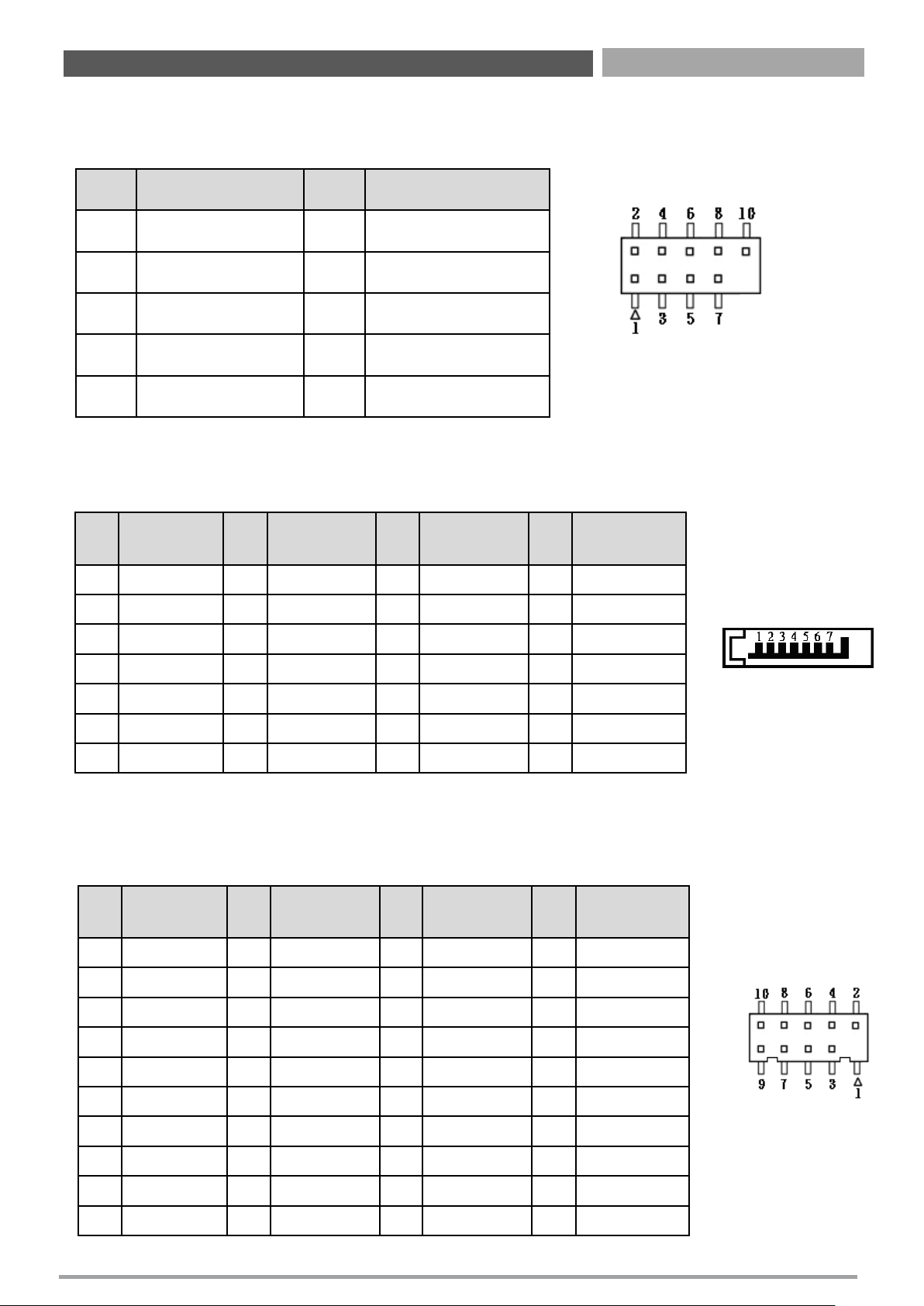
USB78: Front Panel USB2.0 Header
Pin Header Type: 2X5-pin header, 2.54mm pitch
Pin Definition Pin Definition
1 +5V 2 +5V
3 USB2_D7- 4 USB2_D8-
5 USB2_D7+ 6 USB2_D8+
7 GND 8 GND
9 NC 10 GND
SATA1, SATA2, SATA3, SATA4: SATA Connector
Pin
SATA1
Definition
Pin
SATA2
Definition
Pin
SATA3
Definition
Pin
SATA4
Definition
1 GND 1 GND 1 GND 1 GND
2
SATA_TXP0
2
SATA_TXP1
2 SATA_TXP2 2 SATA_TXP3
3
SATA_TXN0
3
SATA_TXN1
3
SATA_TXN2
3 SATA_TXN3
4 GND 4 GND 4 GND 4 GND
5
SATA_RXN0
5
SATA_RXN1
5
SATA_RXN2
5 SATA_RXN3
6
SATA_RXP0
6
SATA_RXP1
6
SATA_RXP2
6 SATA_RXP3
7 GND 7 GND 7 GND 7 GND
COM2, COM3, COM4, COM5: Serial Port Connector
Connector Type: Connector Type: 2X5-pin Wafer, 2.0mm pitch
Pin
COM2
Definition
Pin
COM3
Definition
Pin
COM4
Definition
Pin
COM5
Definition
1 DCD2 1 DCD3 1 DCD4 1 DCD5
2 DSR2 2 DSR3 2 DSR4 2 DSR5
3 RXD2 3 RXD3 3 RXD4 3 RXD5
4 RTS2 4 RTS3 4 RTS4 4 RTS5
5 TXD2 5 TXD3 5 TXD4 5 TXD5
6 CTS2 6 CTS3 6 CTS4 6 CTS5
7 DTR2 7 DTR3 7 DTR4 7 DTR5
8 RI2 8 RI3 8 RI4 8 RI5
9 GND2 9 GND3 9 GND4 9 GND5
10 NC NC NC NC
Chapter 2: Jumper & Connectors
Page 23
CT-XSL01 | User’s Manual
23
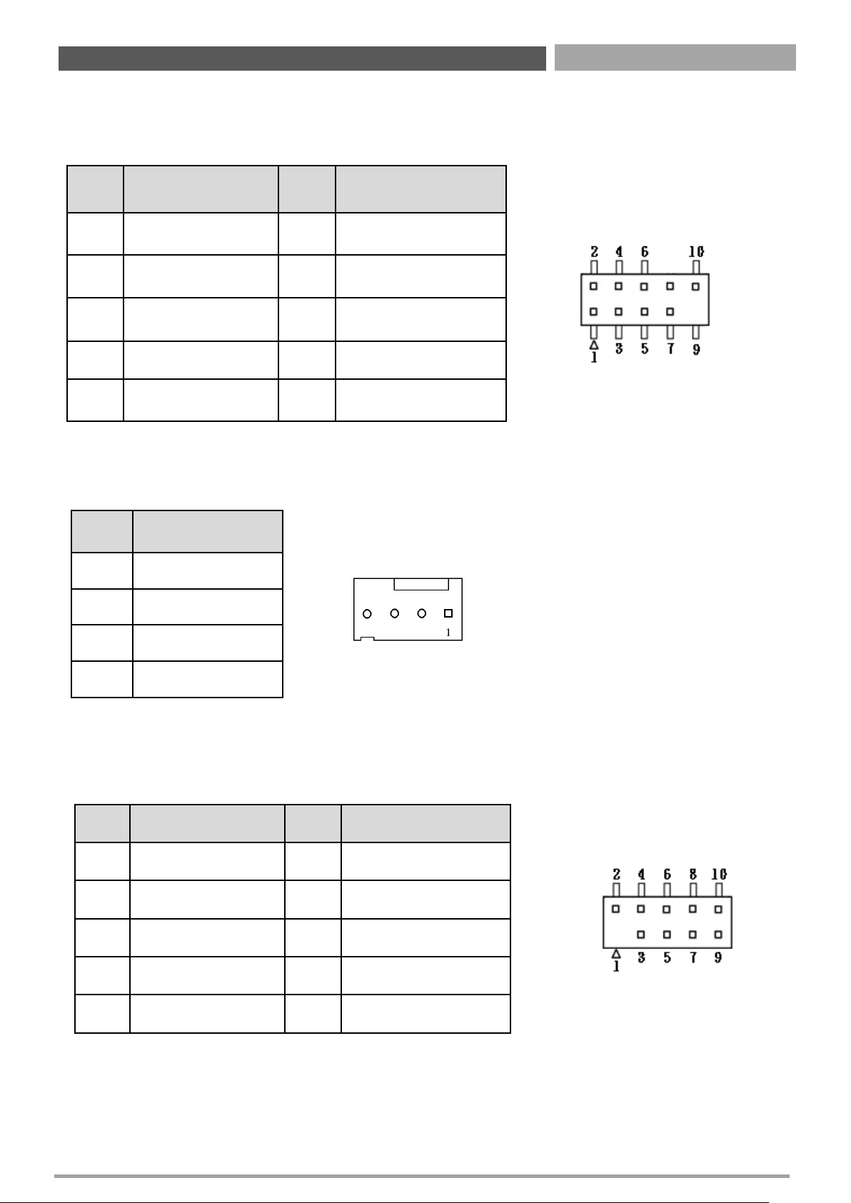
Pin Definition Pin Definition
1 MIC2-IN_L 2 GND
3 MIC2-IN_R 4
PRESENCE#
(Dongle present)
5 LINE2-IN_R 6
MIC2-IN
SENSE_RETURN
7 Jack Detect 8 NC
9 LINE2-IN_L 10
LINE2-IN
SENSE_RETURN
CPU_FAN1, SYS_FAN1: FAN Connector
Pin Definition
1 GND
2 +12V
3 FAN Tachometer
4 FAN PWM
F_PANEL1: Front Panel Header
Pin Header Type: 2X5-pin header, 2.54mm pitch
Pin Definition Pin Definition
1 NC 2 NC
3 GND 4 RESET
5 POWER SWITCH 6 GND
7 SUSPEND LED - 8 HDD LED -
9 POWER LED + 10 HDD LED +
Chapter 2: Jumper & Connectors
Page 24
CT-XSL01 | User’s Manual
24
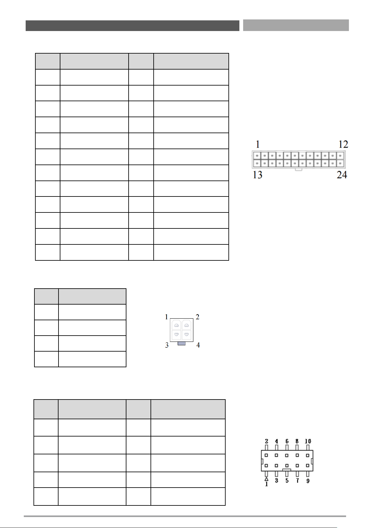
EATXPWR1: Main Power Supply Connector (24pin)
Pin Definition Pin Definition
1 +3.3V 13 +3.3V
2 +3.3V 14 -12V
3 GND 15 GND
4 +5V 16 PS-ON
5 GND 17 GND
6 +5V 18 GND
7 GND 19 GND
8 PWRGD 20 -5V
9 +5VSB 21 +5V
10 +12V 22 +5V
11 +12V 23 +5V
12 +3.3V 24 GND
ATX12V1: Processor Power Supply Connector (4pin)
Pin Definition
1 GND
2 GND
3 +12V
4 +12V
Pin Definition Pin Definition
1 GND 2 +3.3V
3 LPC_AD3 4 NC
5 LPC_AD2 6 RESET
7 LPC_AD1 8 CLK_24MHz
9 LPC_AD0 10 LPC_FRAME#
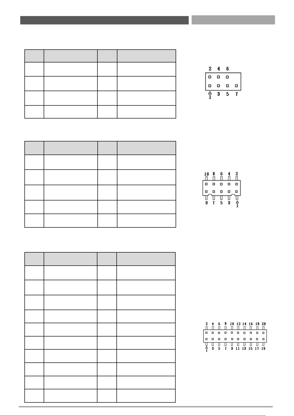
JLPC1: Debug Header
Pin Header Type: 2X5-pin header, 2.0mm pitch
Chapter 2: Jumper & Connectors
Page 25
CT-XSL01 | User’s Manual
25
SPI1: SPI Header
Pin Header Type: 2X4-pin header, 2.0mm pitch
Pin Definition Pin Definition
1 +3.3V 2 GND
3 SPI_CS# 4 SPI_CLK
5 SPI_MISO 6 SPI_MOSI
7 HOLD# 8 NC
JDIO1: GPIO Connector (8 bits)
Connector Type: Connector Type: 2X5-pin Wafer, 2.0mm pitch
Pin Definition Pin Definition
1 +5V 2 GND
3 GPO0 4 GPI0
5 GPO1 6 GPI1
7 GPO2 8 GPI2
9 GPO3 10 GPI3
TPM1: TPM Header
Pin Header Type: 2X10-pin header, 2.0mm pitch
Pin Definition Pin Definition
1 CLK_24MHz 2 GND
3 LPC_FRAME# 4 NC
5 RESET 6 NC
7 LPC_AD3 8 LPC_AD2
9 +3.3V 10 LPC_AD1
11 LPC_AD0 12 GND
13 NC 14 NC
15 +3.3V_DUAL 16 SERIRQ
17 GND 18 GND
19 LPC_PD# 20 NC
Chapter 2: Jumper & Connectors
Page 26
CT-XSL01 | User’s Manual
26
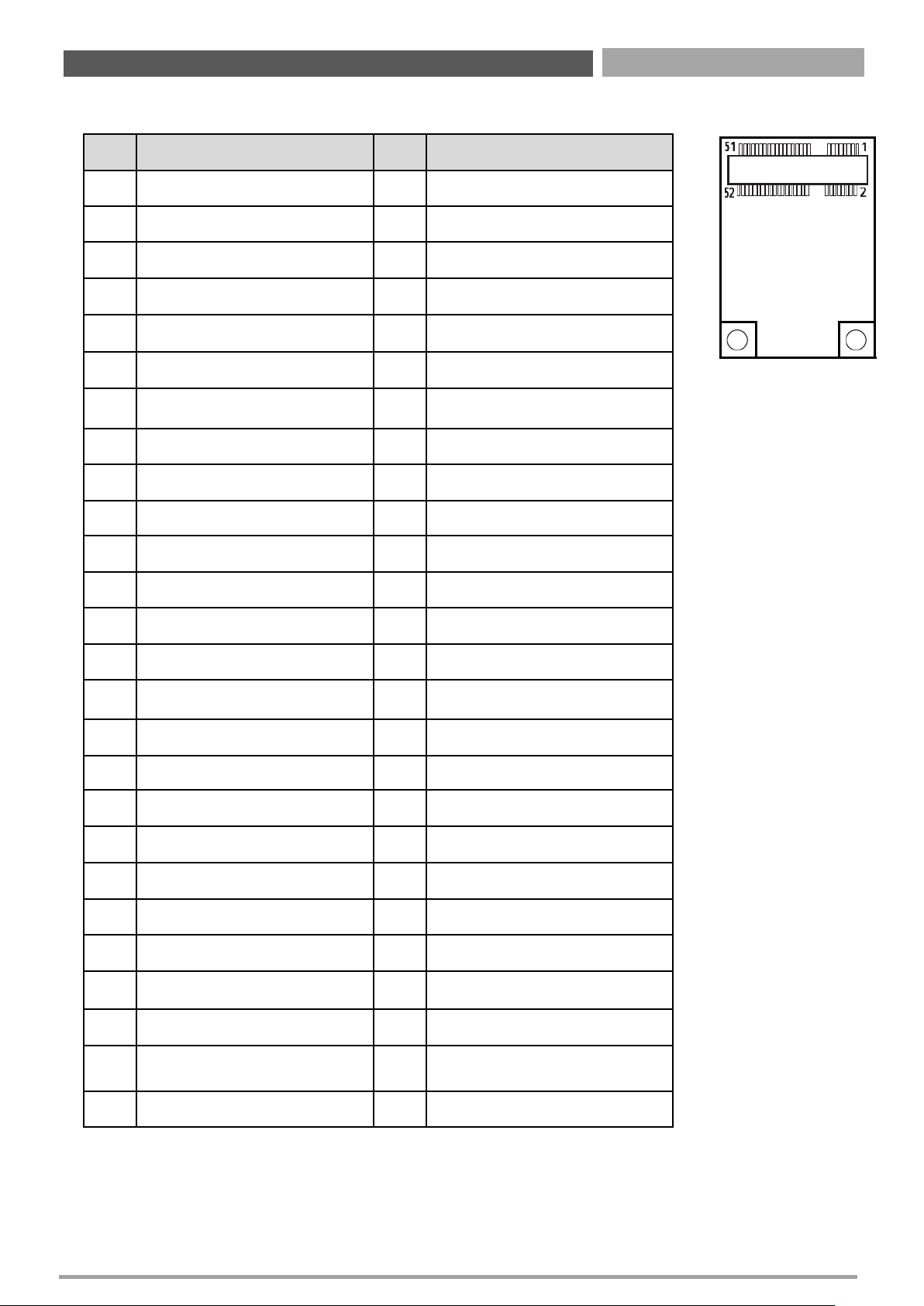
MINI_CARD1_1: Mini PCI-Express / mSATA Socket
Pin Definition Pin Definition
1 WAKE# 27 GND
2 +3.3VSB 28 +1.5V
3 NC 29 GND
4 GND 30 SMB_CLK
5 NC 31 MINIPCIE_TXN (SATA_TXN4)
6 +1.5V 32 SMB_DATA
7 CLKREQ# 33 MINIPCIE_TXP (SATA_TXP4)
8 NC 34 GND
9 GND 35 GND
10 NC 36 USB2_D11-
11 MINIPCIE_CLKN 37 GND
12 NC 38 USB2_D11+
13 MINIPCIE_CLKP 39 +3.3V
14 NC 40 GND
15 GND 41 +3.3V
16 NC 42 NC
17 NC 43 GND
18 GND 44 NC
19 NC 45 NC
20 NC 46 NC
21 GND 47 NC
22 RESET 48 +1.5V
23
MINIPCIE_RXN (SATA_RXN4)
49 NC
24 +3.3V 50 GND
25 MINIPCIE_RXP (SATA_RXP4) 51 Presence Detection
26 GND 52 +3.3V
Chapter 2: Jumper & Connectors
Page 27
CT-XSL01 | User’s Manual
27
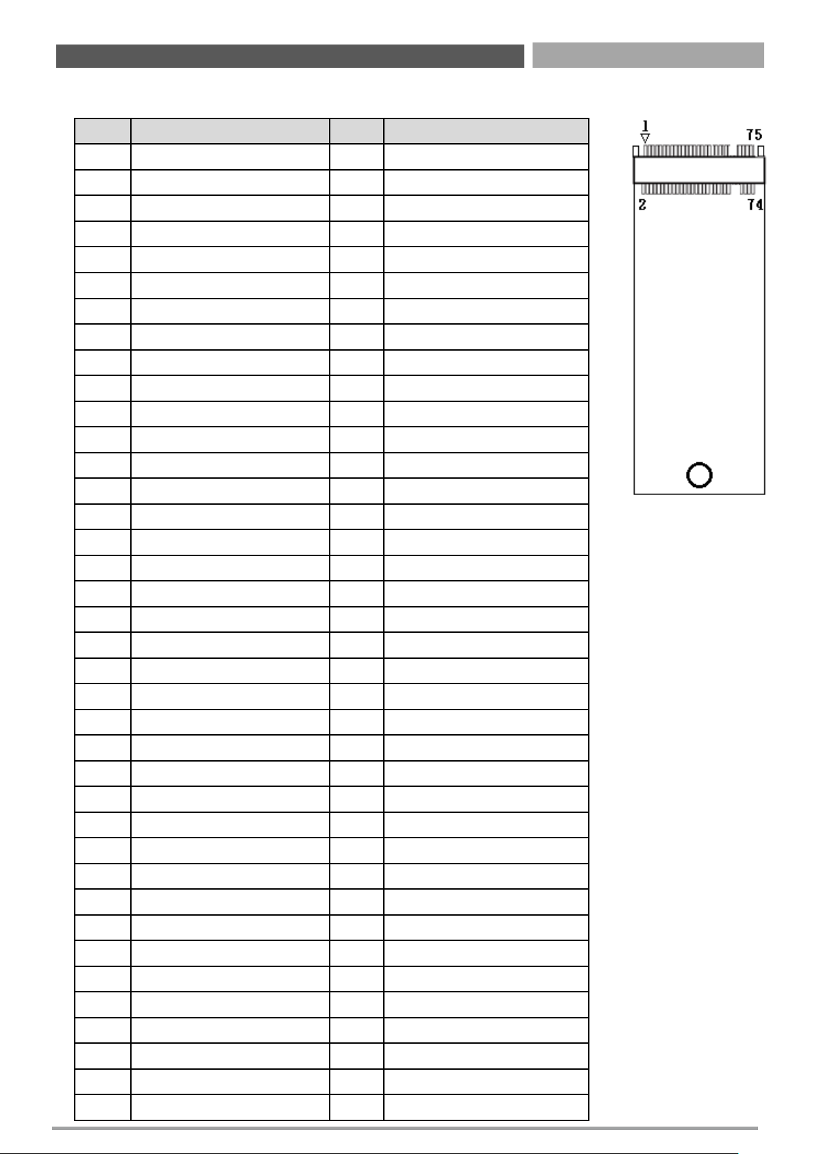
NGFF1: M.2 Socket
Pin Definition Pin Definition
1 GND 2 +3.3V
3 GND 4 +3.3V
5 NC 6 NC
7 NC 8 NC
9 GND 10 NC
11 NC 12
+3.3V
13 NC 14
+3.3V
15 GND 16
+3.3V
17 NC 18
+3.3V
19 NC 20
NC
21 GND 22
NC
23 NC 24
NC
25 NC 26
NC
27 GND 28
NC
29 NC 30
NC
31 NC 32
NC
33 GND 34
NC
35 NC 36
NC
37 NC 38 SATA_DEVSLP
39 GND 40
NC
41 SATA_RXP5 42
NC
43 SATA_RXN5 44
NC
45 GND 46
NC
47 SATA_TXN5 48
NC
49 SATA_TXP5 50 RESET
51 GND 52 M2_CLKREQ#
53 M2_CLKN 54 WAKE#
55 M2_CLKP 56
NC
57 GND 58
NC
59 NC 60 NC
61 NC 62 NC
63 NC 64 NC
65 NC 66 NC
67 NC 68 PCH_SUSCLK
69 SATA/PCIE_Detection 70
+3.3V
71 GND 72
+3.3V
73 GND 74
+3.3V
75 GND 76
Chapter 2: Jumper & Connectors
Page 28
CT-XSL01 | User’s Manual
28
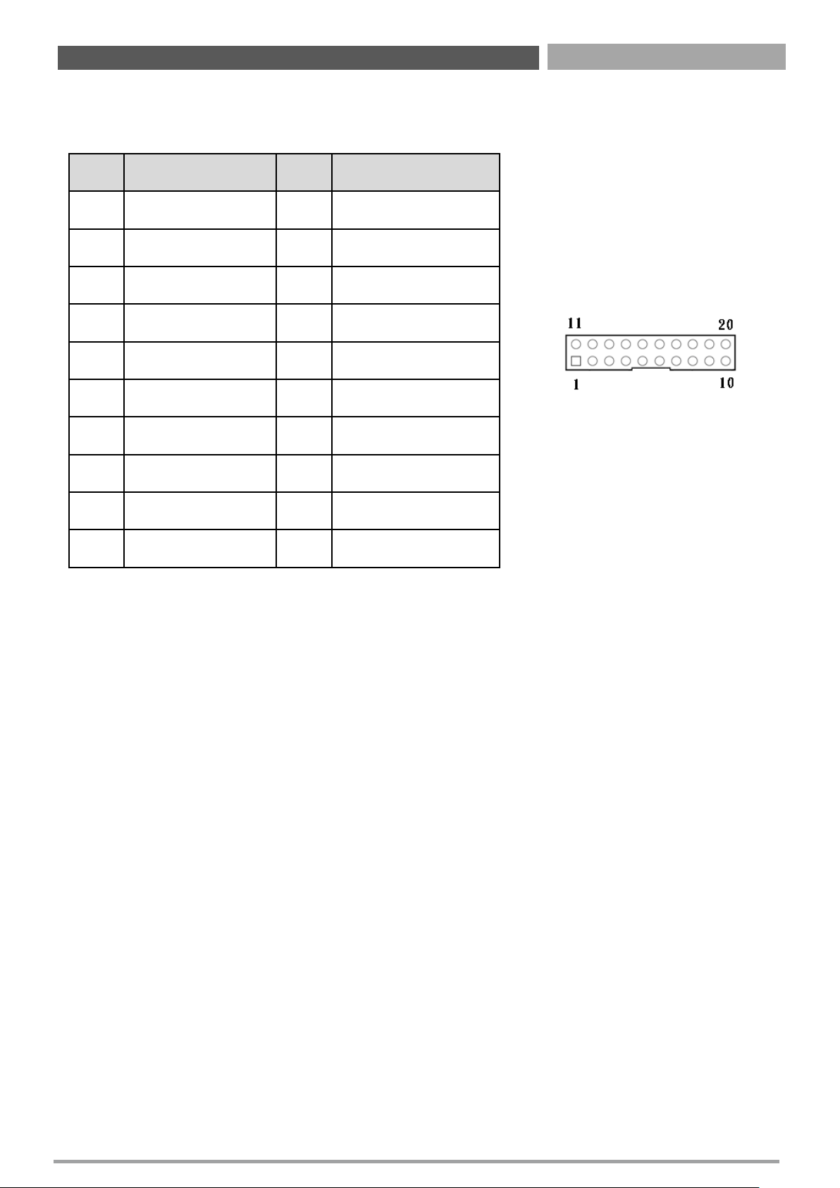
USB56: USB3.0 Connector
Connector Type: 2X10 20-pin box header, 2.0mm pitch
Pin Definition Pin Definition
1
+5V_DUAL
11
USB2_D6+
2 USB3_RX5- 12 USB2_D6-
3
USB3_RX5+
13
GND
4 GND 14 USB3_TX6+
5
USB3_TX5-
15
USB3_TX6-
6 USB3_TX5+ 16 GND
7
GND
17
USB3_RX6+
8 USB2_D5- 18 USB3_RX6-
9
USB_D5+
19
+5V_DUAL
10 NC 20 NC
Chapter 2: Jumper & Connectors
Page 29
CT-XSL01 | User’s Manual
29
2.3 Jumpers Definition
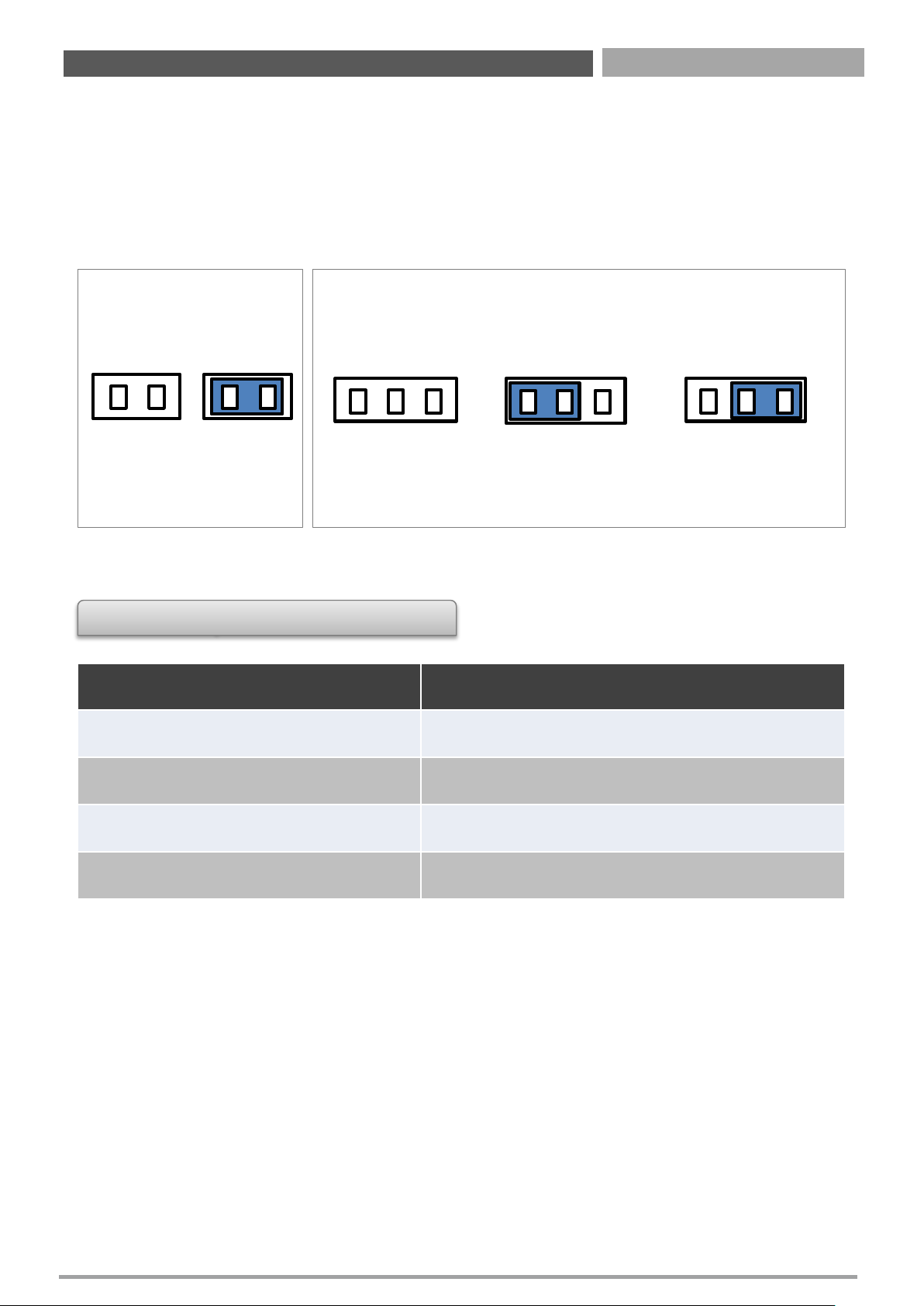
When setting the jumpers, ensure that the jumper caps are placed on the correct pins.
When the jumper cap is placed on both pins, the jumper is short. If you remove the
jumper cap, or place the jumper cap on just one pin, the jumper is open. Refer to below
for examples of the 2-pin and 3-pin jumpers when they are short (on) and open (off).
List of Jumpers
Connectors Location Definition
JLVDS2
Backlight
Power Select Header
JPSON
1
AT
/ ATX Mode Select Header
CLCMOS
1
Clear
CMOS Select Header
JSATA
1
Mini
PCI-Express / mSATA Select Header
1
2
Open
1 2
Short
Two-Pin Jumpers
1
2 3
Pins 1 and 2 are
short
1
2
3
All pins are open
1
2 3
Pins 2 and 3 are
short
Three-Pin Jumpers
Chapter 2: Jumper & Connectors
Page 30
CT-XSL01 | User’s Manual
30
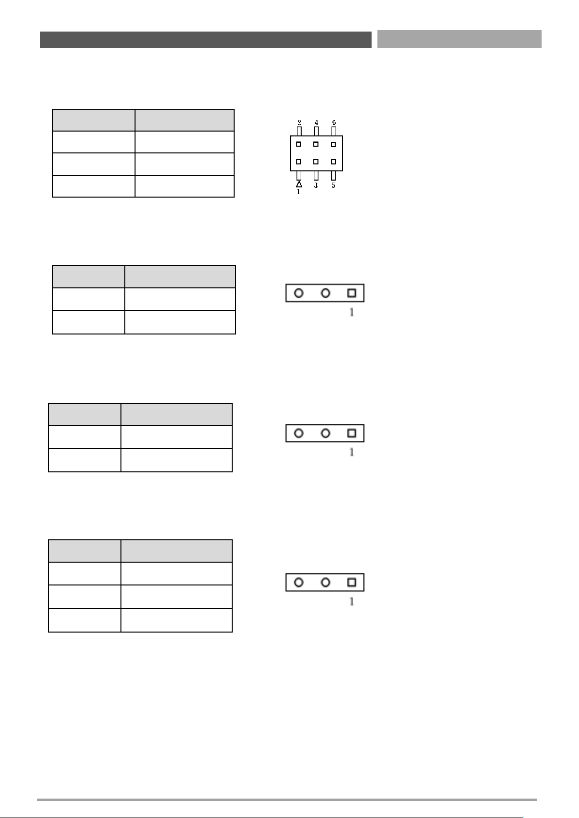
JLVDS2: Backlight Power Select Header
Pin Header Type: 2X3-pin header, 2.0mm pitch
Pin Definition
1-3 (Short) +5V
3-5 (Short) +3.3V
3-4 (Short) +12V
JPSON1: AT / ATX Mode Select Header
Pin Header Type: 1X3-pin header, 2.54mm pitch
Pin Definition
1-2 (Short) ATX Mode
2-3 (Short) AT Mode
CLCMOS1: Clear CMOS Select Header
Pin Header Type: 1X3-pin header, 2.0mm pitch
Pin Definition
1-2 (Short) Normal
2-3 (Short) Clear CMOS
JSATA1: Mini PCI-Express / mSATA Select Header
Pin Header Type: 1X3-pin header, 2.0mm pitch
Pin Definition
1-2 (Short) Auto
2-3 (Short) mSATA
NC Mini PCI-Express
Chapter 2: Jumper & Connectors
Page 31

Chapter 3
Features & Interface
Page 32
CT-XSL01 | User’s Manual
3.1 General Purpose Input Output (GPIO)
GPI and GPO pins may be implemented as GPIO. GPI and GPO pins may be implemented as SDIO.
3.1.1 GPIO Configuration
Board Design
Notes
1. Output pin default setting is “HIGH”
The GPIO function is provided by Nuvoton NCT6106D, and it can be accessed through its GPIO
index/data port. To access the GPIO register, write index to the index port, and then read/write from/to
data port. The configuration on the CT-XSL01 is described as below.
32
Chapter 3: Features & Interface
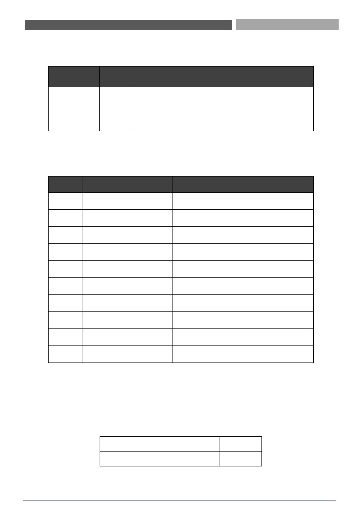
Signal I/O Description
GPO[0:3] O
General purpose output pins. Upon a hardware reset, these
outputs should be low.
GPI[0:3] I
General purpose input pins. Pulled high internally on the
Module.
Pin# GPIO# Default Configuration
1 ― +5V
2 ― GND
3 SIO_OUT0 GPO0
4 SIO_IN0 GPI0
5 SIO_OUT1 GPO1
6 SIO_IN1 GPI1
7 SIO_OUT2 GPO2
8 SIO_IN2 GPI2
9 SIO_OUT3 GPO3
10 SIO_IN3 GPI3
SIO_CONFIG_INDEX_PORT 0x2Eh
SIO_CONFIG_DATA_PORT 0x2Fh
Page 33
CT-XSL01 | User’s Manual
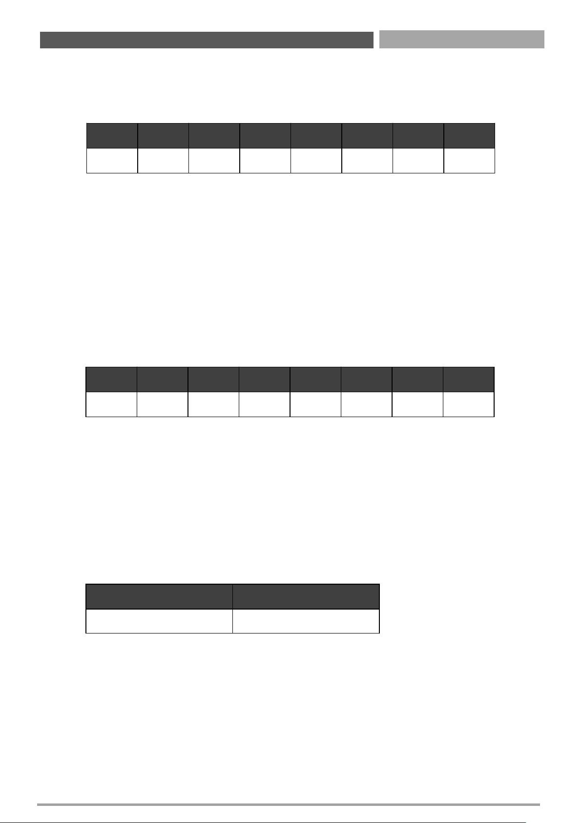
Registers Description
GPIO I/O Select
I/O Register: 0xEC
Note.
Bit X = 0 means Input Mode
Bit X = 1 means Output Mode
The GPIO function is provided by Nuvoton NCT6106D, and it can be accessed through its GPIO
index/data port. To access the GPIO register, write index to the index port, and then read/write from/to
data port. The configuration on the CT-XSL01 is described as below.
GPIO I/O Select
Data Register: 0xED
Note.
Bit X = 0 outputs 0 when in output mode
Bit X = 1 outputs 1 when in output mode
3.2 Watchdog Timer
3.2.1 Board Design
The Watchdog Timer (WDT) is implemented by Nuvoton NCT6106D.
33
Chapter 3: Features & Interface
Bit 7 Bit 6 Bit 5 Bit 4 Bit 3 Bit 2 Bit 1 Bit 0
GPO3 GPO2 GPO1 GPO0 GPI3 GPI2 GPI1 GPI0
Bit 7 Bit 6 Bit 5 Bit 4 Bit 3 Bit 2 Bit 1 Bit 0
GPO3 GPO2 GPO1 GPO0 GPI3 GPI2 GPI1 GPI0
Register Address
WDT Base Address 0xF0h
Page 34
CT-XSL01 | User’s Manual
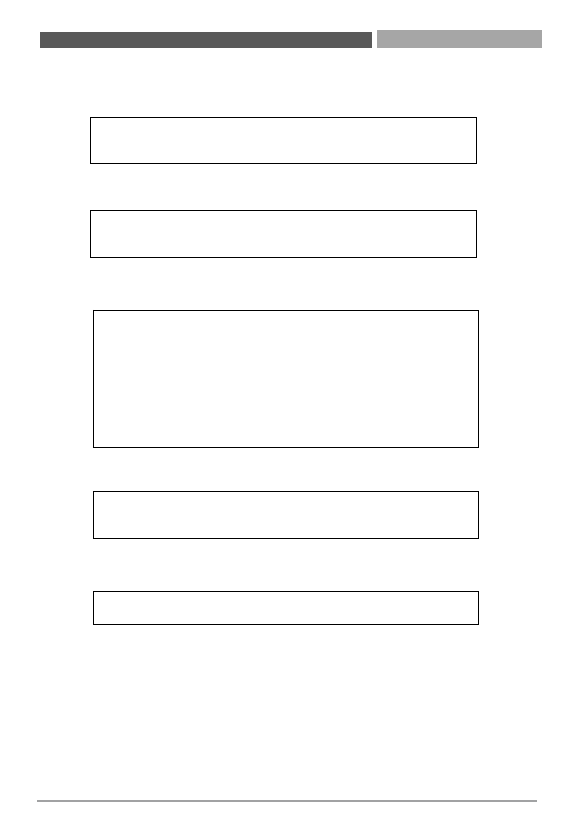
3.2.2 Psuedo Code
Enter_Config
Select Logical Device: 8
Set WDT Time Unit (Second Unit)
Set WDT Time Value
Exit_Config
34
Chapter 3: Features & Interface
Step1: outportb(0x2e, 0x87);
Step2: outportb(0x2e, 0x87);
Step1: outportb(0x2e, 0x07);
Step2: outportb(0x2e, 0x07);
Step1: outportb(0x2e, 0xf0);
Step2: buf2 = inportb(0x2f) & 0xf4; //clear "Select Watchdog Timer I count mode"
Step3: buf2 |= 0x02; //Enable the Watchdog Timer I output low pulse to
the KBRST# pin
Step4: // buf2 |= 0x08; //Bit3 = (1:Minute Mode/0:Second Mode)
Step5: outportb (0x2f, buf2); //Write back
Step1: outportb (0x2e, 0xf1)
Step2: outportb (0x2f, Time)
//Set watch dog time value
//Set watch dog time value
Step1: outportb(0x2e, 0xaa);
Page 35
CT-XSL01 | User’s Manual
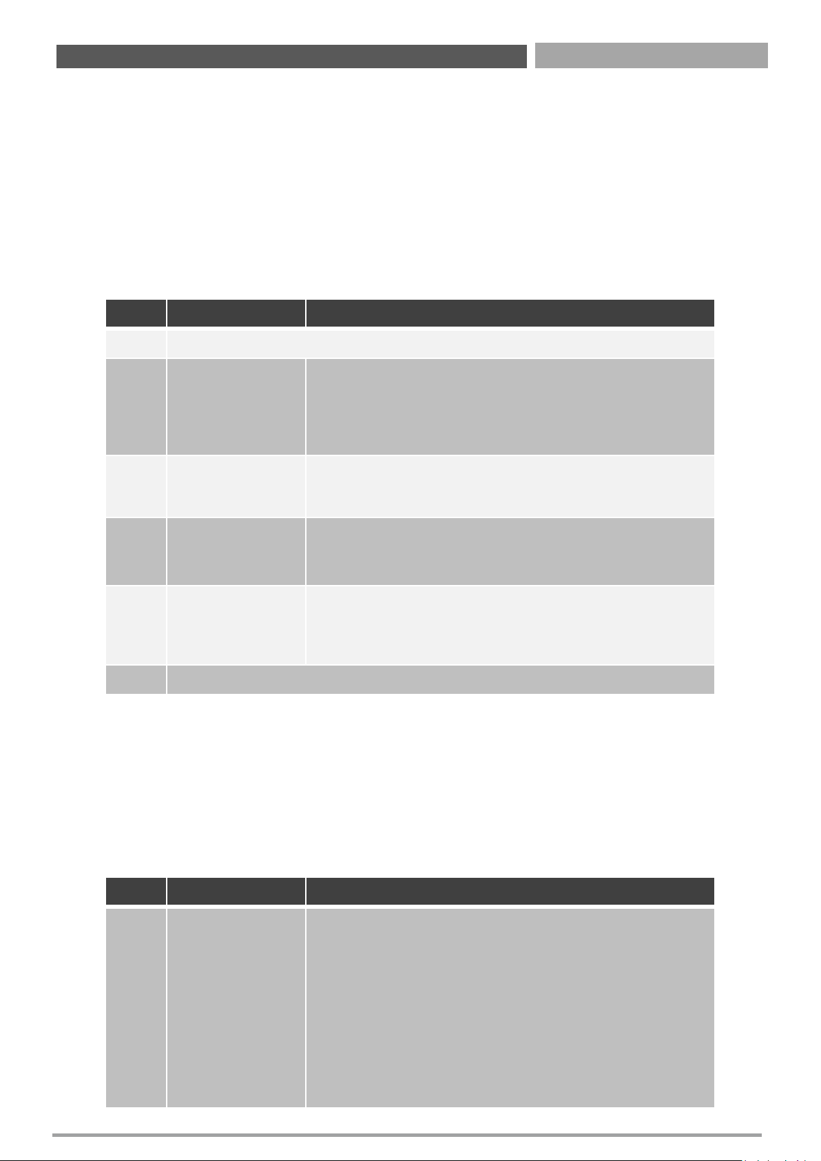
Watchdog Timer:
Logical Device: 8
CR F0h. Watchdog Timer I (WDT1) and KBC P20 Control Mode Register
Location: Address F0h
Attribute: Read/Write
Power Well: VCC
Reset by: LRESET# or PWROK
Default: 00h
Size: 8 bits
CR F1h. Watchdog Timer I (WDT1) Counter Register
Location: Address F1h
Attribute: Read/Write
Power Well: VCC
Reset by: LRESET# or PWROK
Default: 04h
Size: 8 bits
35
Chapter 3: Features & Interface
BIT READ / WRITE DESCRIPTION
7/5 Reserved.
4 R/W
Watchdog Timer | count mode is 1000 times faster.
0: Disable.
1: Enable.
(If bit-3 is 0, the count mode is 1/1000 second mode.)
(If bit-3 is 1, the count mode is 1/1000 minutes mode.)
3 R/W
Select Watchdog Timer | count mode.
0: Second Mode.
1: Minute Mode.
2 R/W
Enable the rising edge of KBC reset (P20) to issue a time-
out event.
0: Disable.
1: Enable.
1 R/W
Disable / Enable the Watchdog Timer | output low pulse to the
KBRST# pin (PIN59)
0: Disable.
1: Enable.
0 Reserved.
BIT READ / WRITE DESCRIPTION
7/0 R/W
Watchdog Timer I Time-out value. Writing a non-zero value to
this register causes the counter to load the value into the Watch
Dog Counter and start counting down. If CR F2h, bits 7 and 6 are
set, any Mouse Interrupt or Keyboard Interrupt event causes the
previously-loaded, non-zero value to be reloaded to the Watch
Dog Counter and the count down resumes. Reading this register
returns the current value in the Watch Dot Counter, not the
Watch Dog Timer Time-out value.
00h: Time-out Disable
01h: Time-out occurs after 5.03x10⁷CLKIN cycle time, by analogy.
(5.03x107x (1/48MHz) = 1.046s)
Page 36

Chapter 4
BIOS Setup
Page 37
CT-XSL01 | User’s Manual
37
4.1 BIOS Introduction
The system BIOS software is stored on EEPROM. The BIOS provides an interface to modify the
configuration. When the battery is removed, all the parameters will be reset.
BIOS Setup
Power on the embedded system and by pressing <Del> or <F2> immediately allows you to enter the
setup screens. If the message disappears before you respond and you still wish to enter the Setup, restart
the system by turning it OFF and ON or pressing the RESET button.
You may also restart the system by simultaneously pressing <Ctrl>, <Alt>, and <Delete> keys.
Main Setup
The main menu lists the setup functions you can make changes to. You can use the arrow keys ( ↑↓ ) to
select the item. The on-line description of the highlighted setup function is displayed at the bottom of
the screen.
General Help <F1>
The BIOS setup program provides a General Help screen. You can call up this screen from any menu by
simply pressing <F1>. The Help screen lists the appropriate keys to use and the possible selections for the
highlighted item. Press <Esc> to exit the Help screen.
Chapter 4: BIOS Setup
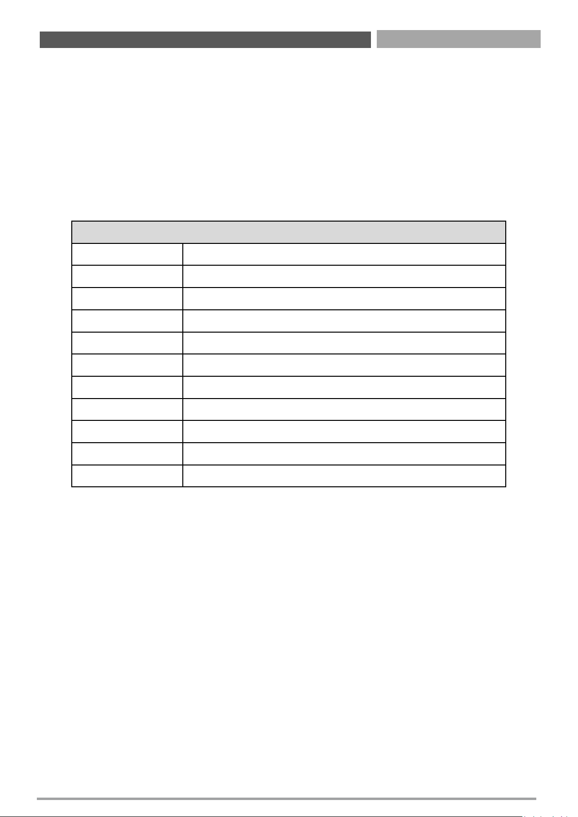
Control Keys
<←> <→>
Select Screen
<↑> <↓>
Select Item
<Enter>
Select
<Page Up/+>
Increases the numeric value or makes changes
<Page Down/
->
Decreases the numeric value or makes changes
<F1>
General Help
<F2>
Previous Value
<F3>
Load Optimized Defaults
<F4>
Save Configuration and Exit
<Tab>
Select Setup Fields
<Esc>
Exit BIOS Setup
Page 38
CT-XSL01 | User’s Manual
38
4.2 Main Setup
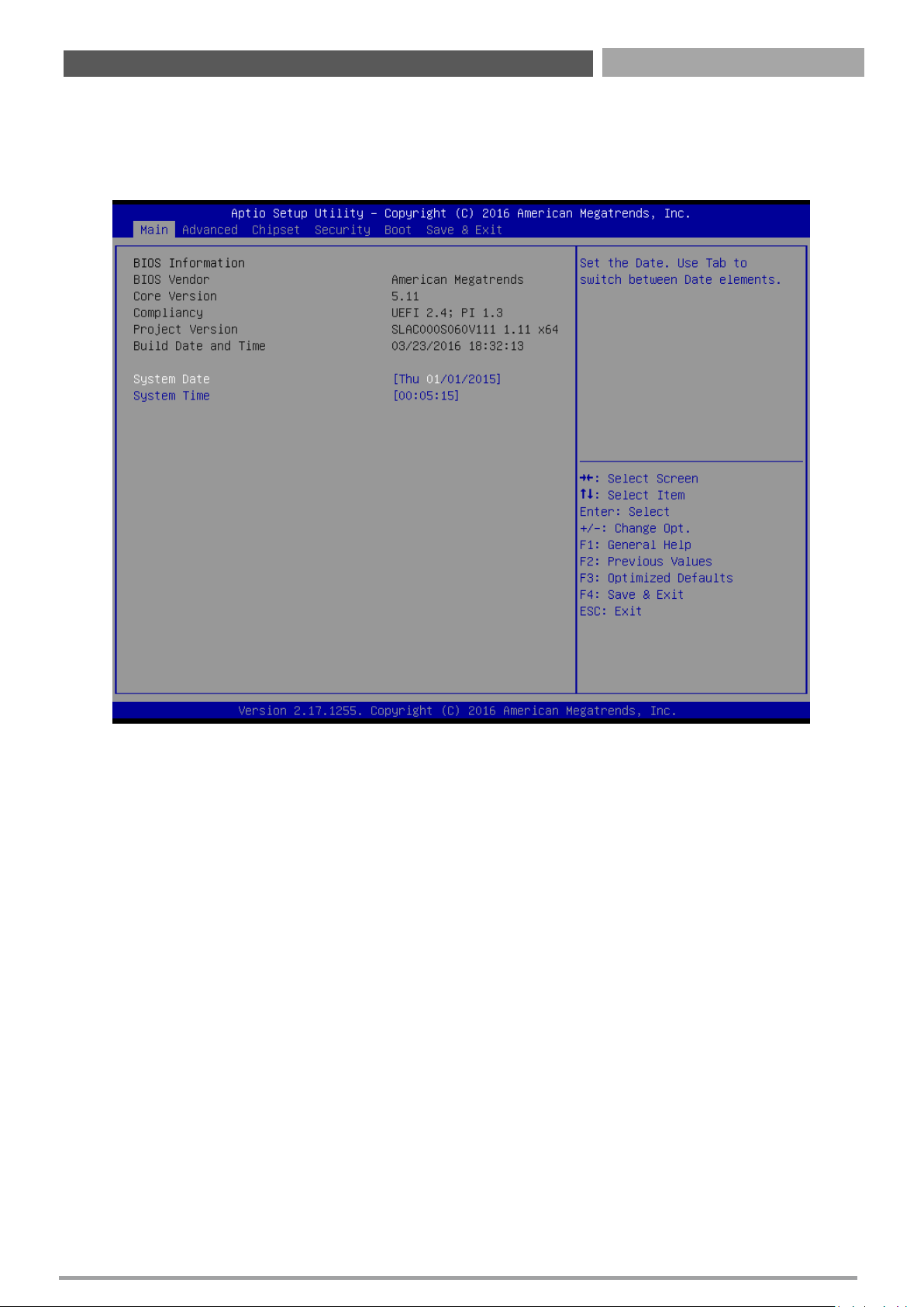
Press <Del> to enter BIOS CMOS Setup Utility. The Main setup screen is showed as following
when the setup utility is entered. System Date/Time is set up in the Main Menu.
4.2.1 System Date
Set the system date. Please use <Tab> to switch between data elements.
4.2.2 System Time
Set the system time. Please use <Tab> to switch between time elements.
Chapter 4: BIOS Setup
Page 39
CT-XSL01 | User’s Manual
39
4.3 Advanced Setup
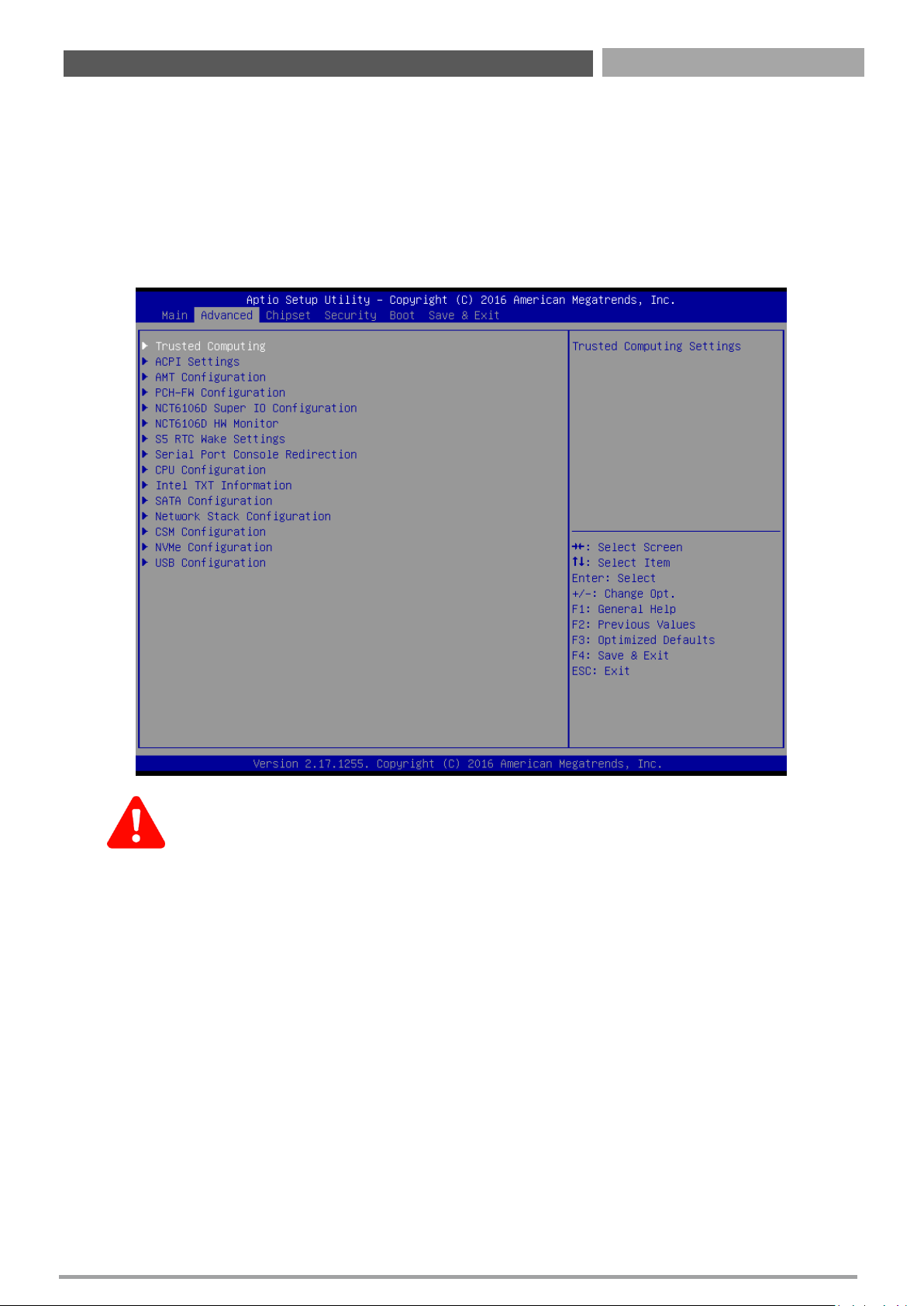
Select the Advanced tab from the setup screen to enter the Advanced BIOS Setup screen.
You can select any of the items in the left frame of the screen, such as Chipset configuration, to
go to the sub menu for that item. You can display an Advanced BIOS Setup option by highlighting
it using the <Arrow> keys. All Advanced BIOS Setup options are described in this section. The
Advanced BIOS Setup screen is shown below. The sub menus are described on the following
pages.
Take caution when changing the settings of the Advanced menu items. Incorrect
field values can cause the system to malfunction.
Chapter 4: BIOS Setup
Page 40
CT-XSL01 | User’s Manual
40
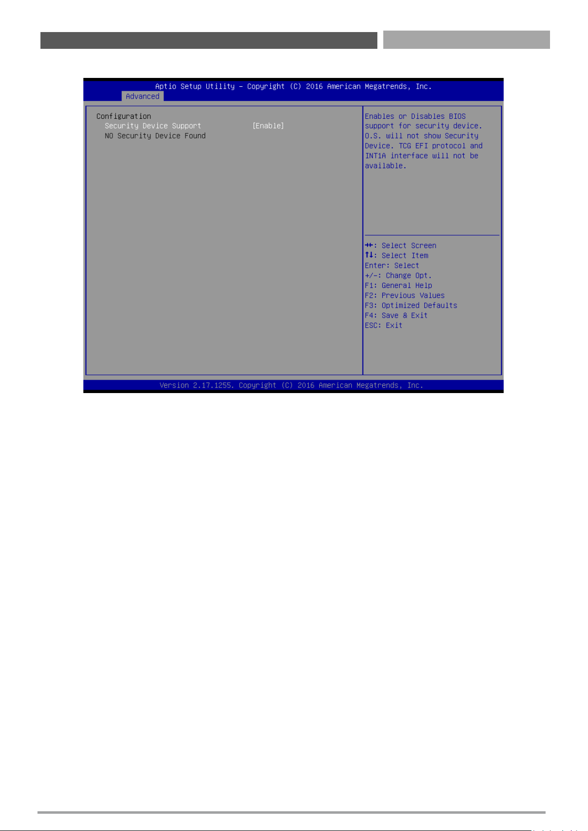
4.3.1 Trusted Computing
■ Security Device Support
This item allows you to enable or disable BIOS support for security device.
Chapter 4: BIOS Setup
Page 41
CT-XSL01 | User’s Manual
41
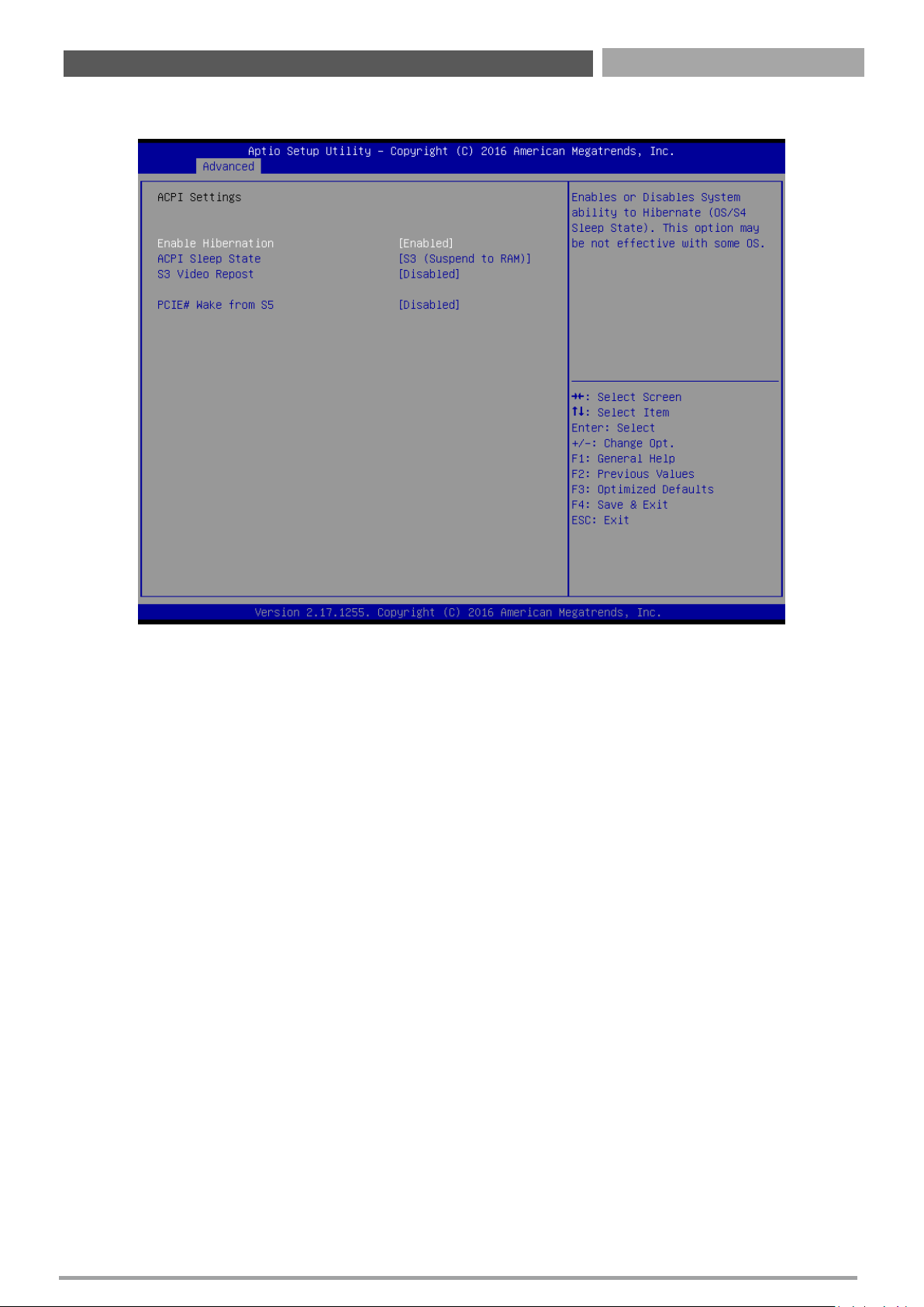
4.3.2 ACPI Settings
■ Enable Hibernation
Enable or Disable system ability to Hibernation.
Configuration options: [Enable] [Disable]
■ ACPI Sleep State
Select the highest ACPI sleep state the system will enter the SUSPEND button is press.
Configuration options: [Suspend Disable] [S3 only(suspend to RAM )]
■ S3 Video Repost
Enable or disable S3 video repost
Configuration options: [Disabled] [Enabled]
■ PCIE# Wake from S5
Enable or disable PCIE wake the system from S5.
Configuration options: [Disabled] [Enabled]
Chapter 4: BIOS Setup
Page 42
CT-XSL01 | User’s Manual
42
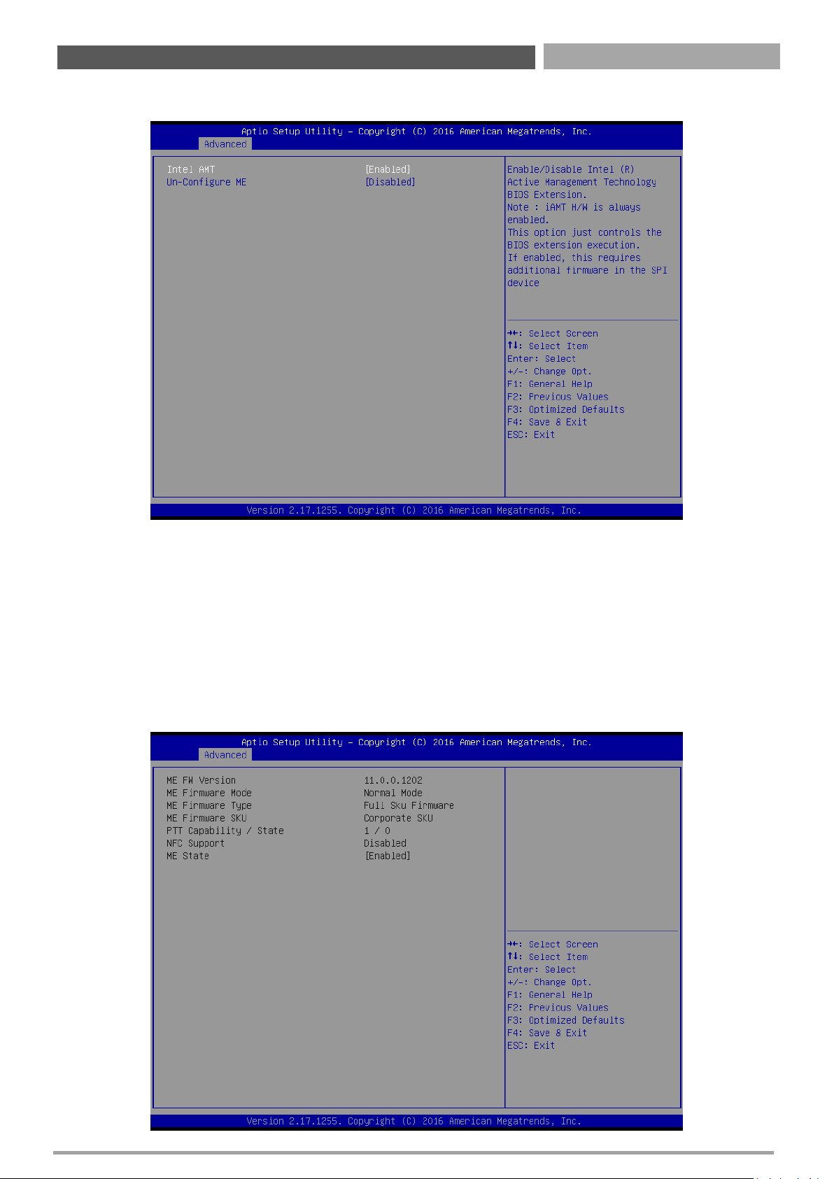
4.3.3 AMT Configuration
■ Intel AMT
Enable or Disable Intel AMT BIOS extension
Configuration options: [Disabled] [Enabled]
■ Un-configure ME
Un-configure ME with Password
Configuration options: [Disabled] [Enabled]
4.3.4 PCH FW Configuration
Chapter 4: BIOS Setup
Page 43
CT-XSL01 | User’s Manual
43
Chapter 4: BIOS Setup
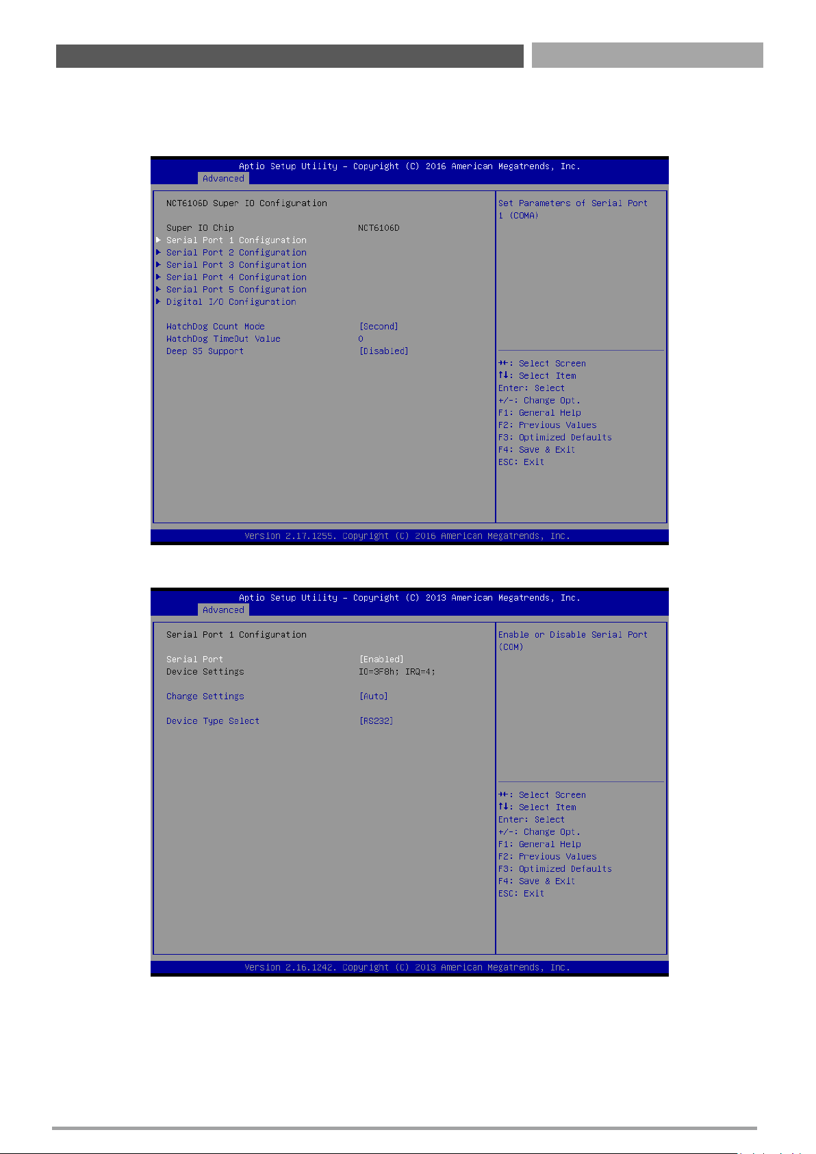
4.3.5 Super IO Configuration
This setting allows you to select options for the NCT6106D Super IO Configuration, and change
the value of the selected option.
■ Serial Port 1 Configuration
Serial Port
This item allows you to enable or disable serial port.
Change Settings
This item allows you to change the address & IRQ settings of the specified serial port.
Device Type Select
Change the Serial interface. Select <RS232> ,<RS422 Full Duplex> or <RS485 Half Duplex>
interface.
Page 44
CT-XSL01 | User’s Manual
44
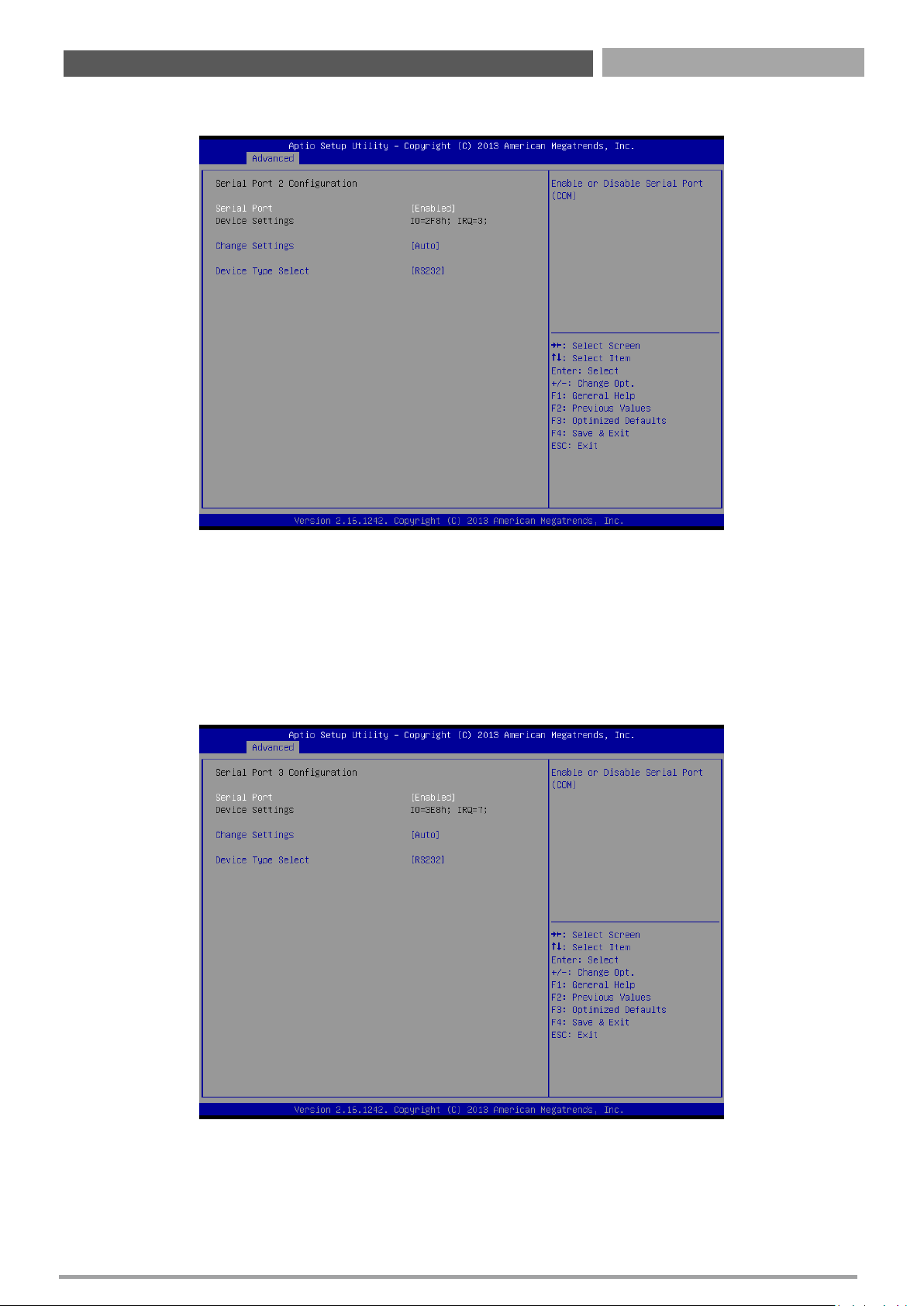
■ Serial Port 2 Configuration
Serial Port
This item allows you to enable or disable serial port.
Change Settings
This item allows you to change the address & IRQ settings of the specified serial port.
Device Type Select
Change the Serial interface. Select <RS232> ,<RS422 Full Duplex> or <RS485 Half Duplex> interface.
■ Serial Port 3 Configuration
Serial Port
This item allows you to enable or disable serial port.
Change Settings
This item allows you to change the address & IRQ settings of the specified serial port.
Device Type Select
Change the Serial interface. Select <RS232> ,<RS422 Full Duplex> or <RS485 Half Duplex> interface.
Chapter 4: BIOS Setup
Page 45
CT-XSL01 | User’s Manual
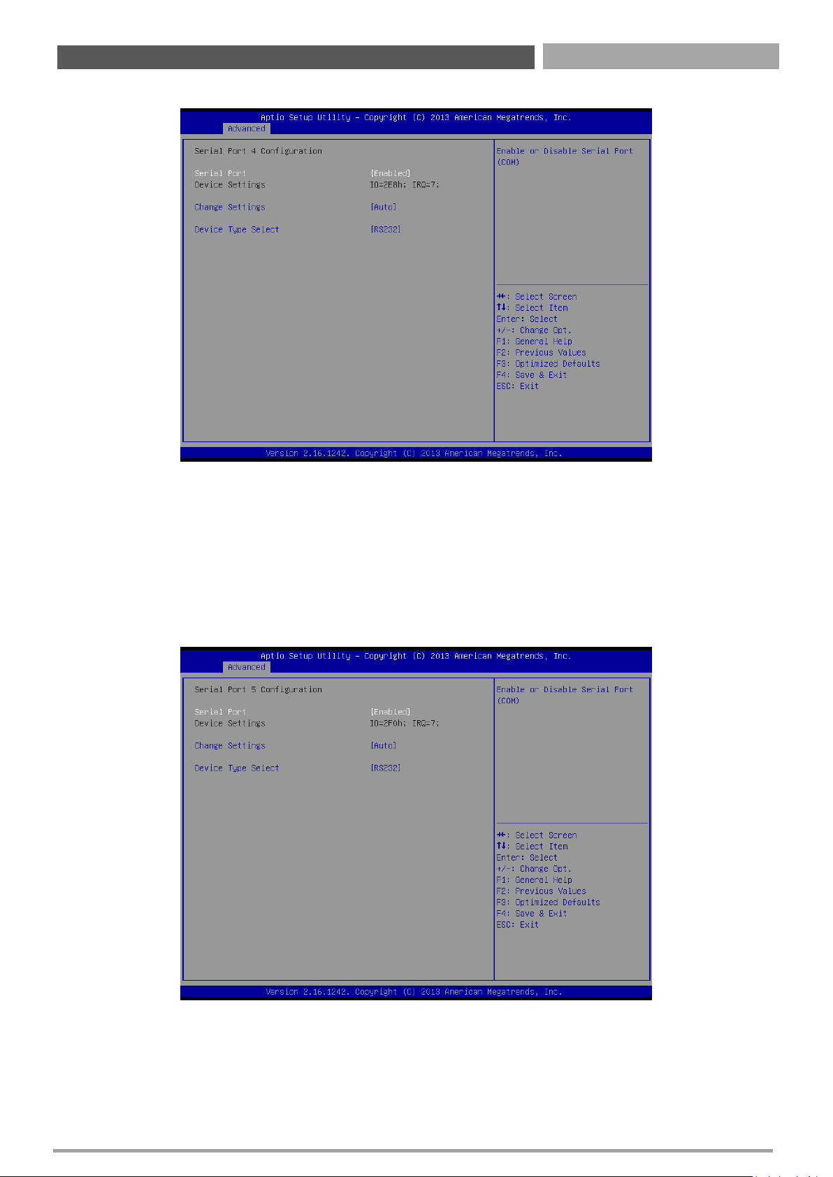
■ Serial Port 4 Configuration
Serial Port
This item allows you to enable or disable serial port.
Change Settings
This item allows you to change the address & IRQ settings of the specified serial port.
Device Type Select
Change the Serial interface. Select <RS232> ,<RS422 Full Duplex> or <RS485 Half Duplex> interface.
■ Serial Port 5 Configuration
Serial Port
This item allows you to enable or disable serial port.
Change Settings
This item allows you to change the address & IRQ settings of the specified serial port.
Device Type Select
Change the Serial interface. Select <RS232> ,<RS422 Full Duplex> or <RS485 Half Duplex> interface.
45
Chapter 4: BIOS Setup
Page 46
CT-XSL01 | User’s Manual
46
Chapter 4: BIOS Setup
■ Watch Dog Function
This setting allows you to setup the system watch-dog timer, a hardware timer that generates a reset
when the software that it monitors does not respond as expected each time the watch dog polls it.
Watch Dog Timer Count Mode
Change the Watch dog mode. Select <Second Mode> or <Minute Mode> mode.
Watch Dog Timer Time Out Value
User can set a value in the range of 0 to 255.
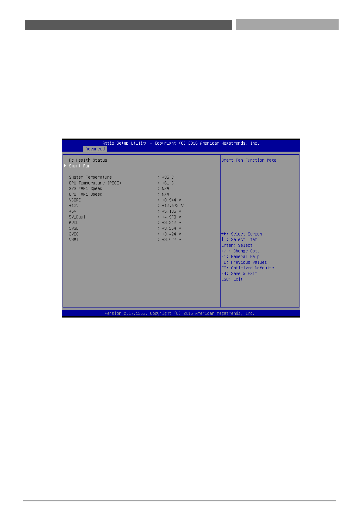
4.3.6 Hardware Monitor
These items display the current status of all monitored hardware devices/ components such as voltages
and temperatures.
■ Smart Fan
This setting allows you to setup the system watch-dog timer, a hardware timer that generates a reset
when the software that it monitors does not respond as expected each time the watch dog polls it.
Watch Dog Timer Count Mode
Change the Watch dog mode. Select <Second Mode> or <Minute Mode> mode.
Watch Dog Timer Time Out Value
User can set a value in the range of 0 to 255.
Page 47
CT-XSL01 | User’s Manual
47
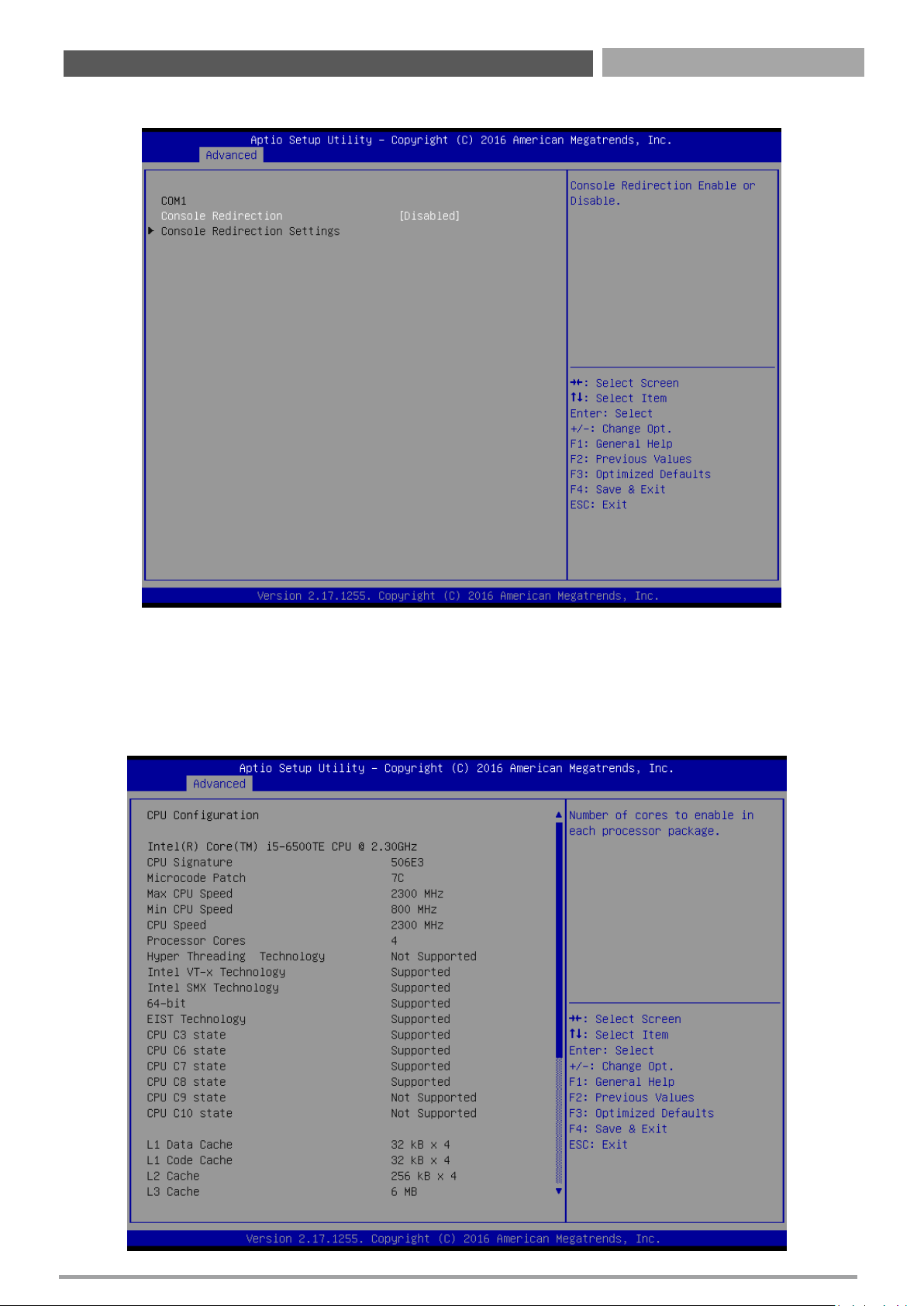
4.3.7 Serial Port Console Redirection
■ Console Redirection
These items allows you to enable or disable COM1~COM5 console redirection.
Chapter 4: BIOS Setup
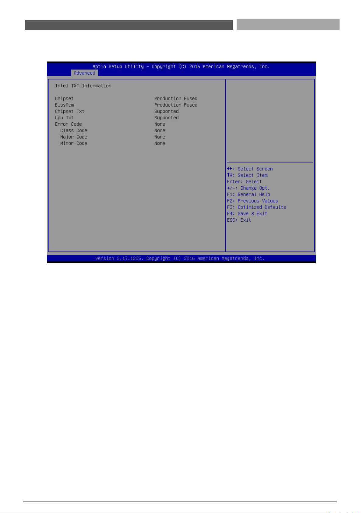
4.3.8 CPU Configuration
Page 48

CT-XSL01 | User’s Manual
48
Chapter 4: BIOS Setup
■ Hyper-Threading [Enabled]
Enabled or Disabled the hyper threading of Intel CPU
Configuration options: [Disabled][Enabled]
This depends on CPU sku.
■ Active Processor Core [All]
Number of Cores to enable in each processor package
Configuration options: [all] [1][2][3][4]
This depends on CPU sku.
■ Intel Virtualization Technology [Enabled]
When enabled, a VWM can utilize the additional hardware capabilities provided by
vanderpool Technology
Configuration options: [Disabled][Enabled]
■ Intel® SpeedStep™ [Enabled]
Allow more than two frequency ranges to be supported.
Configuration options: [Disabled][Enabled]
■ Turbo mode [Enabled]
Enable or disable Turbo mode
Configuration options: [Enabled] [Disabled]
■ CPU C states [Enabled]
Enable or disable CPU C states
Configuration options: [Enabled] [Disabled]
■ Enhanced C-states [Enabled]
Enable or disable C1E. When enabled, CPU will switch to minimum speed when all cores
enter C-state.
Configuration options: [Enabled] [Disabled]
■ Package C state limit [Auto]
Package C state limit
Configuration options: [C0/C1][C2][C3][C6][C7][C7s][C8][Auto]
■ Intel TXT(LT) Support [Disabled]
Enable or disable Intel TXT support
Configuration options: [Enabled] [Disabled]
■ SW Guard Extensions(SGX) [software controlled]
Enable or disables Guard Extensions
Configuration options:[Disabled][Enabled][Software Controlled]
■ Select owner EPOCH input type [No change in owner EPOCHs]
After user enters EPOCH values manually, the values will not be visible for security reasons
Configuration options:[No change in owner EPOCHs][change to new random owner
EPOCHs][Manual user defined owner EPOCHs]
Page 49
CT-XSL01 | User’s Manual
49
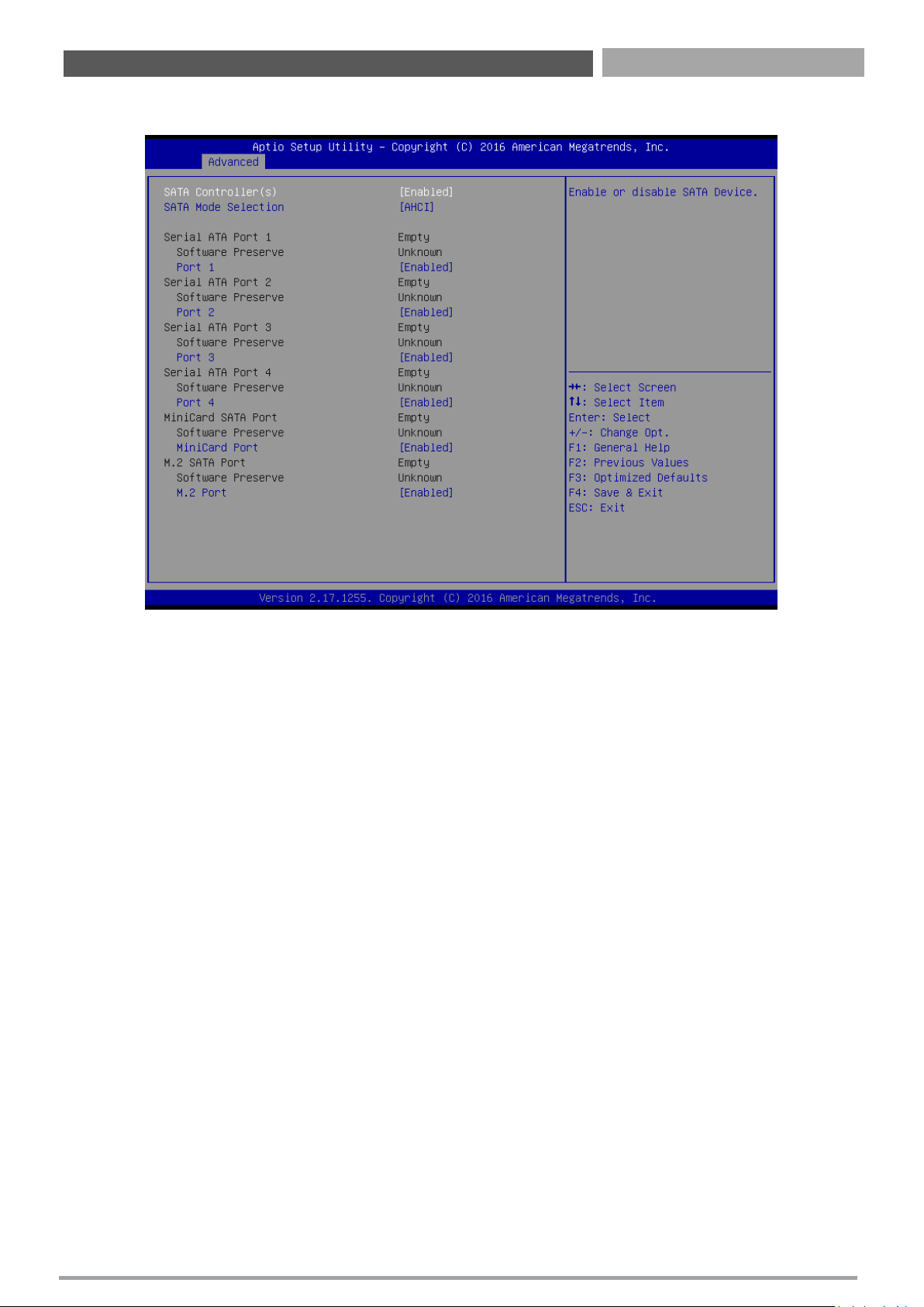
4.3.9 Intel TXT Information
Display Intel TXT information
Chapter 4: BIOS Setup
Page 50
CT-XSL01 | User’s Manual
50
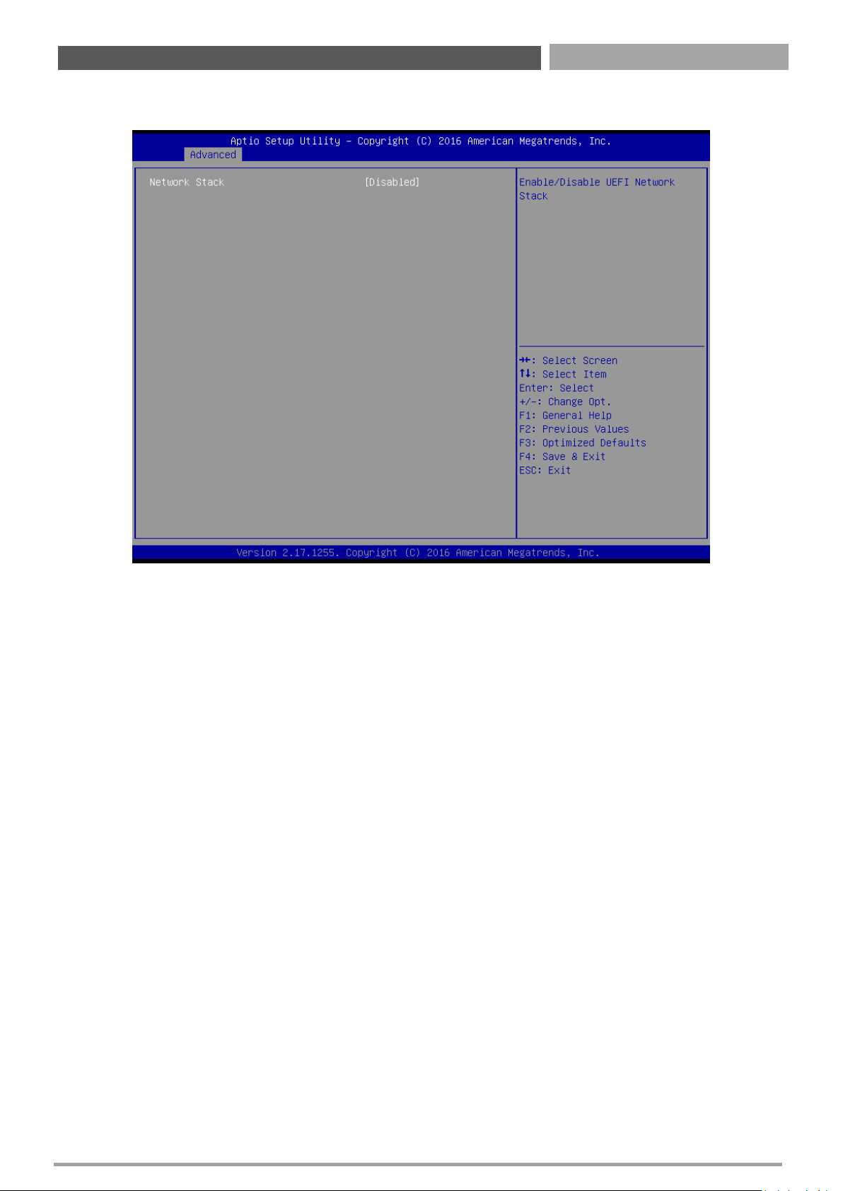
4.3.10 SATA Configuration
■ SATA Controller [Enabled]
Enable or Disable SATA device
Configuration options: [Enabled][Disabled]
■ SATA Mode Selection [AHCI]
Determines how SATA controller operate
Configuration options: [AHCI][RAID]
■ Serial – ATA Port 1
This item allows you to enable or disable Serial-ATA Port 1.
■ Serial – ATA Port 2
This item allows you to enable or disable Serial-ATA Port 2.
■ Serial – ATA Port 3
This item allows you to enable or disable Serial-ATA Port 3.
■ Serial – ATA Port 4
This item allows you to enable or disable Serial-ATA Port 4.
■ MiniCard SATA Port
This item allows you to enable or disable mSATA.
■ M.2 SATA Port
This item allows you to enable or disable M.2 SATA Port.
Chapter 4: BIOS Setup
Page 51
CT-XSL01 | User’s Manual
51
4.3.11 Network Stack Configuration
■ Network Stack [Disabled]
Enabled or disabled UEFI Network Stack
Configuration options: [Disabled] [Enabled]
Chapter 4: BIOS Setup
Page 52
CT-XSL01 | User’s Manual
52
4.3.12 Compatibility Support Module Configuration
■ CSM Support
Enabled or disabled CSM Support
Configuration options: [Disabled] [Enabled]
■ Boot option filter
This option controls Legacy/UEFI ROMs Priority
Configuration options: [UEFI and Legacy] [Legacy Only][UEFI Only]
■ Network [UEFI]
Control the execution of UEFI and Legacy PXE OpROM
Configuration options: [Do not launch] [UEFI][Legacy]
■ Storage [UEFI]
Control the execution of UEFI and Legacy Storage OpROM
Configuration options: [Do not launch] [UEFI][Legacy]
■ Video [UEFI]
Control the execution of UEFI and Legacy Video OpROM
Configuration options: [Do not launch] [UEFI][Legacy]
■ Other PCI devices [UEFI]
Determines OpROM execution policy for devices other than Network, Storage, or Video.
Configuration options: [Do not launch] [UEFI][Legacy]
Chapter 4: BIOS Setup
Page 53
CT-XSL01 | User’s Manual
53
4.3.13 NVMe Configuration
Chapter 4: BIOS Setup
Page 54
CT-XSL01 | User’s Manual
54
4.3.14 USB Configuration
■ Legacy USB Support [Enabled]
Enabled Legacy USB Support. Auto Option disables legacy support if no USB devices are
connected. Disabled option will keep USB devices available only for EFI application.
Configuration options: [Disabled] [Enabled][Auto]
■ XHCI Hand-off [Enabled]
This is a workaround for OSes without XHCI hand-off support. This XHCI ownership change
should be claimed by XHCI drivers
Configuration options: [Disabled] [Enabled]
■ USB Mass storage Driver Support[Enabled]
Enabled or Disabled USB Mass storage driver support.
Configuration options: [Disabled] [Enabled]
■ JetFlashTranscend 16GB 8.07 [Auto]
Mass storage device emulation type. ‘Auto’ enumerates devices according to their media
format. Optical drives are emulated as ‘CDROM’, drives with no media will be emulated
according to a drive type.
Configuration options: [Auto] [Floopy][Forced FDD][hard Disk][CD-ROM]
Chapter 4: BIOS Setup
Page 55
CT-XSL01 | User’s Manual
55
4.4 Chipset
4.4.1 System Agent Configuration
This section provides configure options for on-graphic, PEG port, and installed memory.
Chapter 4: BIOS Setup
Page 56
CT-XSL01 | User’s Manual
56
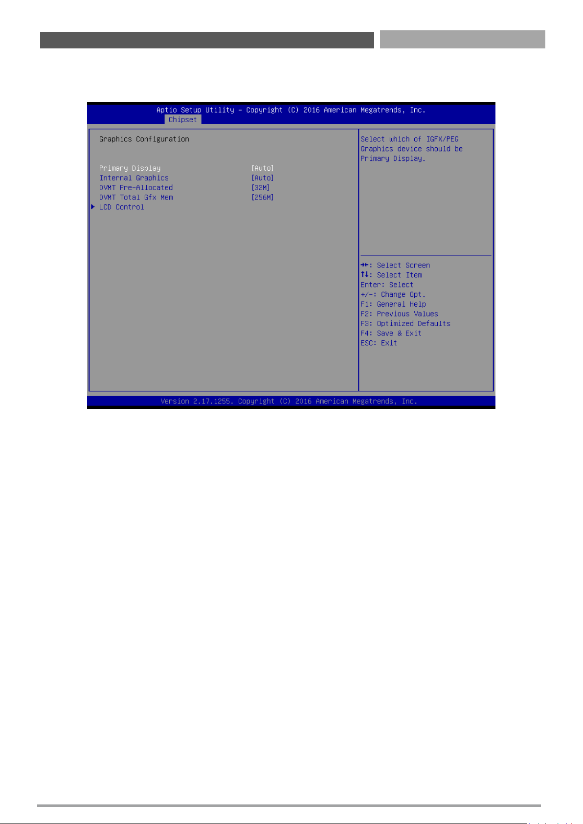
■ Graphic Configuration
This section provides onboard graphics-related configuration options.
Primary Display
Select which of IGFX/PEG/PCI graphic device should be primary display or select SG for switchable
GFx.
Configuration options: [Auto] [IGFX][PEG][PCIE]
Internal Graphics
Keep IGFX enabled based on the setup options
Configuration options: [Auto] [disabled][enabled]
DVMT Pre-Allocated
This item selects DVMT 5.0 Pre-Allocated (Fixed) Graphics Memory size used by the Internal
Graphics Device. . Select <64M>, <96M>, <128M>, <160M>, <192M>, <224M>, <256M>, <288M>,
<320M>, <352M>, <384M>, <416M>, <448M>, <480M>, <512M>, <1024M>, <1536M>, or
<2048>.
DVMT Total Gfx Mem
This item selects DVMT5.0 Total Graphic Memory size used by the Internal Graphics Device. Select
<128MB>, <256MB> or <Max>.
Chapter 4: BIOS Setup
Page 57
CT-XSL01 | User’s Manual
57
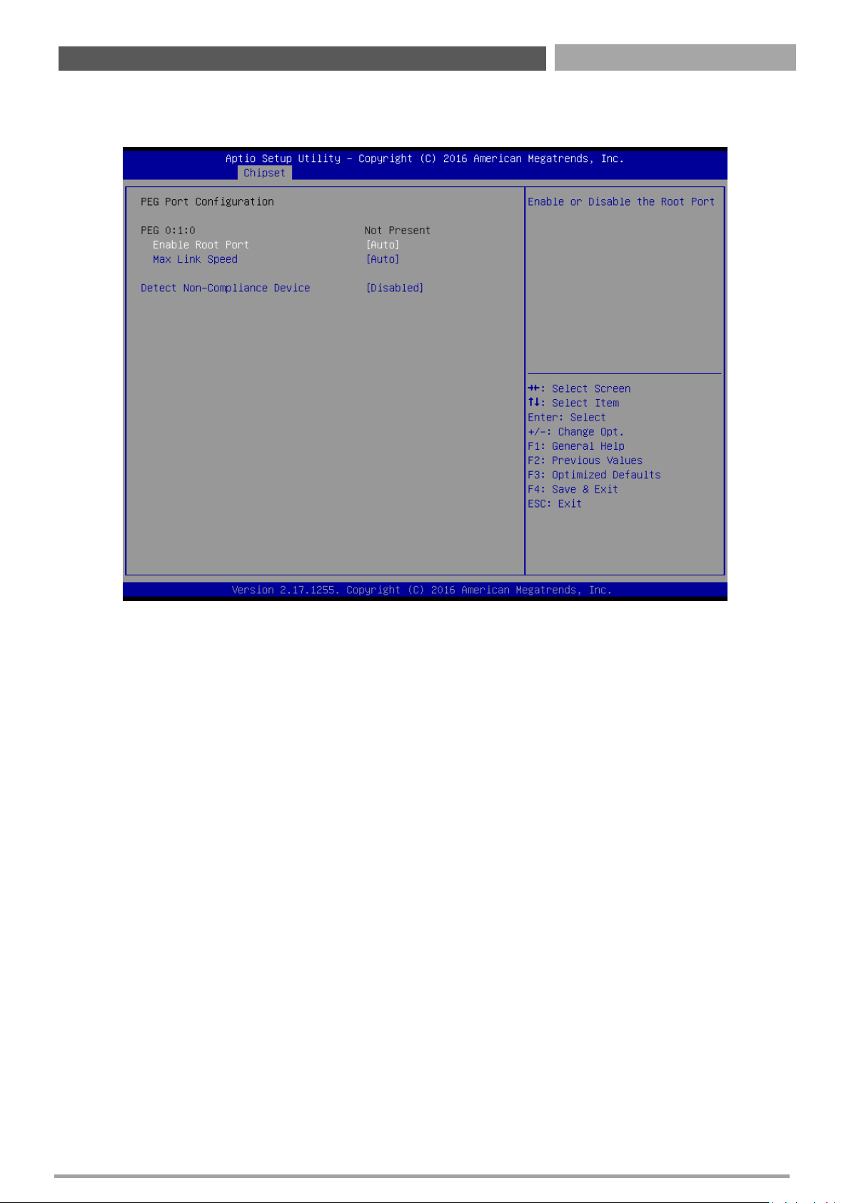
■ PEG Port Configuration
This section provides PEG Port configuration options.
Enable root Port [Auto]
Enable or Disable the root port
Configuration options: [Disabled][Enabled][Auto]
Max Link Speed [Auto]
Configure PEG 0:1:0 Max Speed
Configuration options: [Auto][Gen1][Gen2][Gen3]
Detect Non-Compliance Device [Disabled]
Detect non-compliance PCI express Device in PEG
Configuration options: [Disabled][Enabled]
Chapter 4: BIOS Setup
Page 58
CT-XSL01 | User’s Manual
58
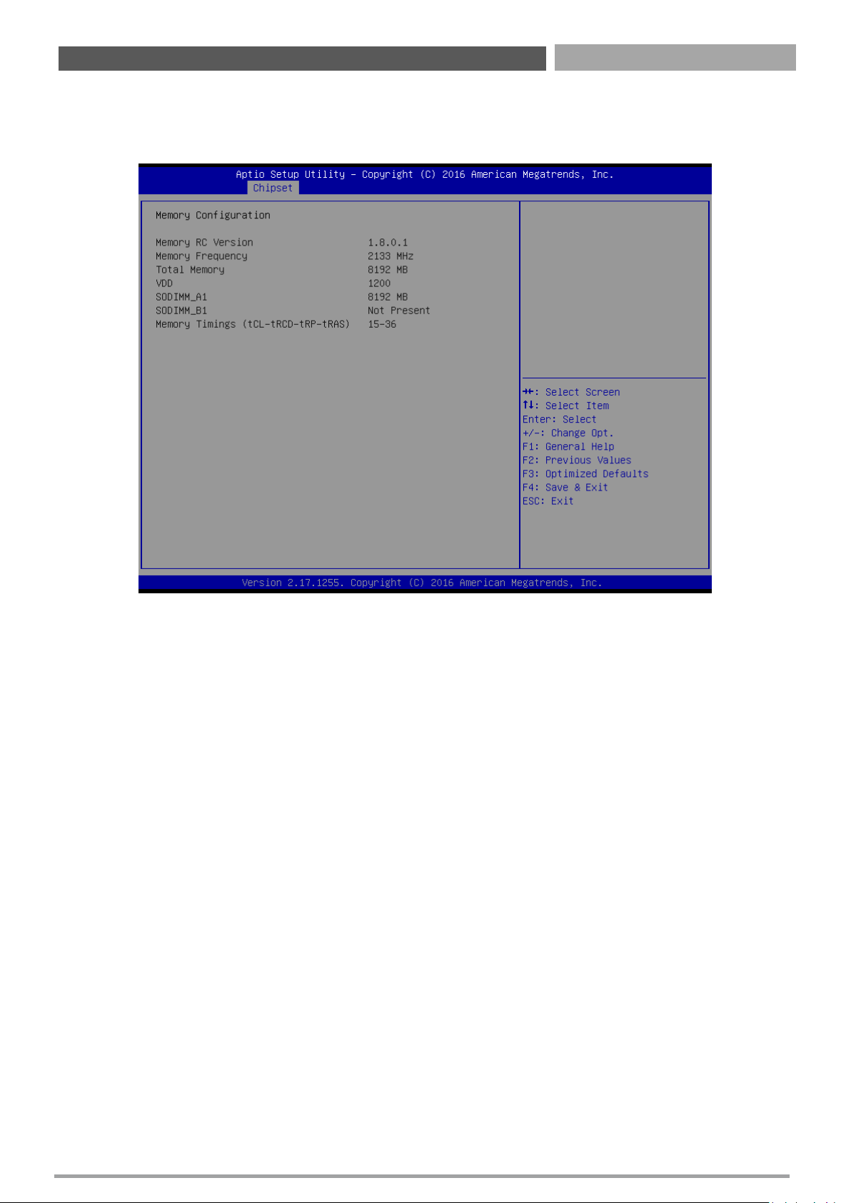
■ Memory Configuration
This section provides installed memory information.
Chapter 4: BIOS Setup
Page 59
CT-XSL01 | User’s Manual
59
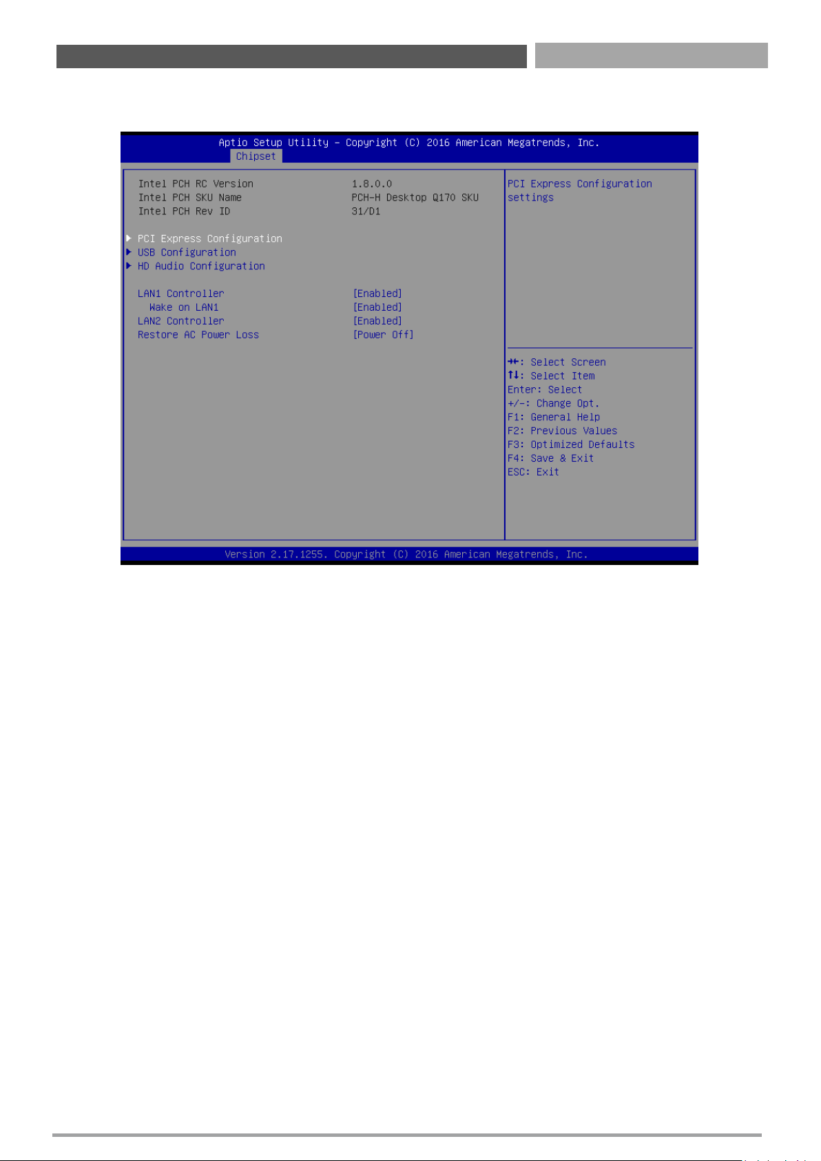
4.4.2 PCH-IO Configuration
■ Lan1 Controller [Enabled]
Enable or Disable onboard Lan1
Configuration options: [Disabled][Enabled]
■ Wake on lan [Auto]
Enable or Disable integrated LAN to wake the system
Configuration options: [Disabled][Enabled]
■ Lan2 Controller [Enabled]
Enable or Disable onboard Lan2
Configuration options: [Disabled][Enabled]
■ Restore AC power Loss [Power off]
Specify what state to go to when power is re-applied after a power failure.
Configuration options: [Power on][Power off][Last State]
Chapter 4: BIOS Setup
Page 60
CT-XSL01 | User’s Manual
60
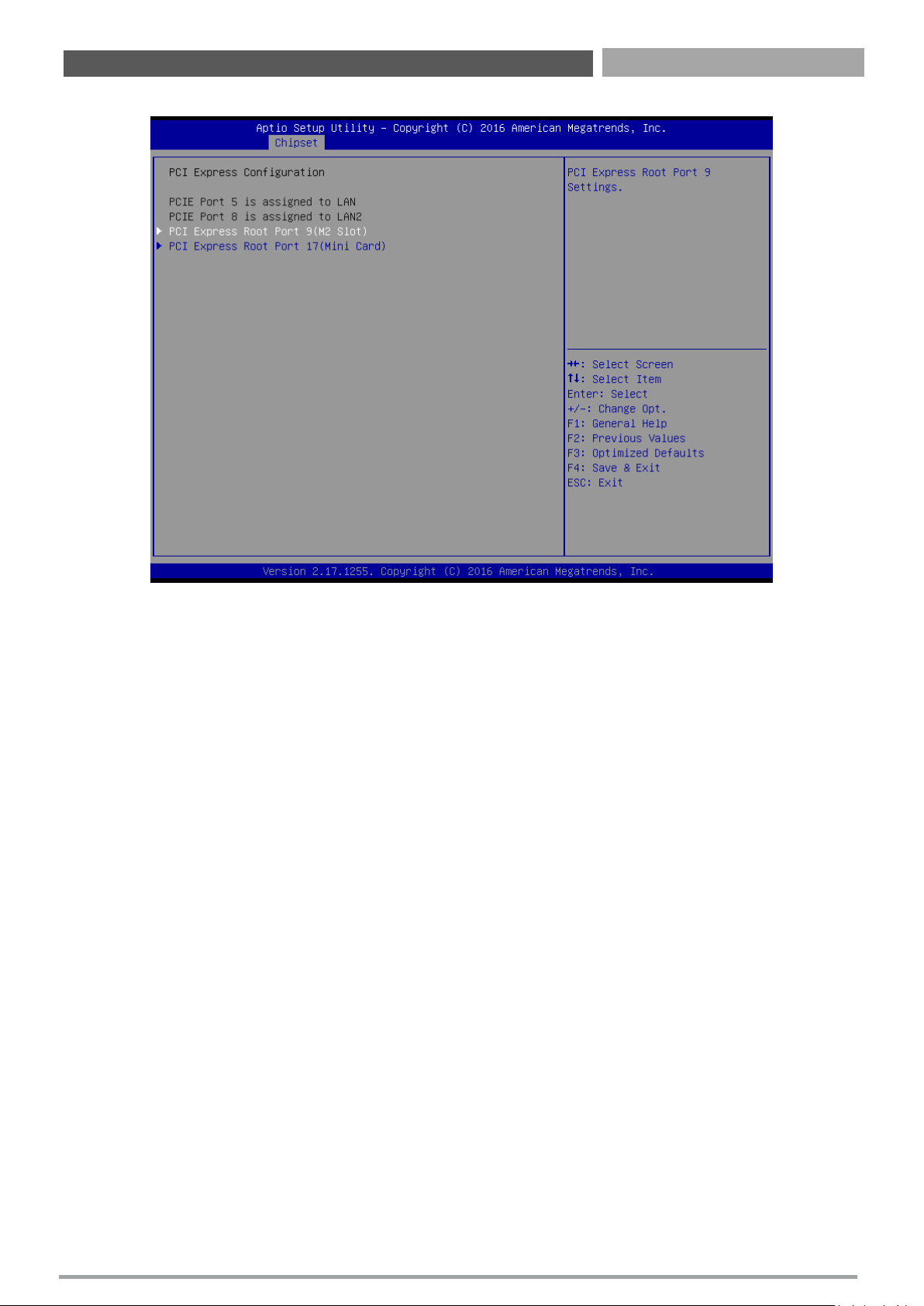
■ PCI Express Configuration
PCI Express Root Port 9 [Enabled]
Control the PCI Express Port
Configuration options: [Disabled][Enabled]
ASPM Support [Disabled]
Set the ASPM level: Force L0s- Force all links to L0s State; Auto- BIOS auto configure; DisabledDisables ASPM
Configuration options: [Disabled][L0s][L1][L0sL2][Auto]
PCIe Speed [Auto]
Select PCI Express Port speed
Configuration options: [Auto][Gen1][Gen2][Gen3]
Detect Non-compliance device [Disabled]
Detect non-compliance PCI express Device, If enabled, it will take more time at Post time.
Configuration options: [Disabled][Enabled]
PCI Express Root Port 17 [Enabled]
Control the PCI Express Port
Configuration options: [Disabled][Enabled]
ASPM Support [Disabled]
Set the ASPM level: Force L0s- Force all links to L0s State; Auto- BIOS auto configure; DisabledDisables ASPM
Configuration options: [Disabled][L0s][L1][L0sL2][Auto]
PCIe Speed [Auto]
Select PCI Express Port speed
Configuration options: [Auto][Gen1][Gen2][Gen3]
Detect Non-compliance device [Disabled]
Detect non-compliance PCI express Device, If enabled, it will take more time at Post time.
Configuration options: [Disabled][Enabled]
Chapter 4: BIOS Setup
Page 61
CT-XSL01 | User’s Manual
61
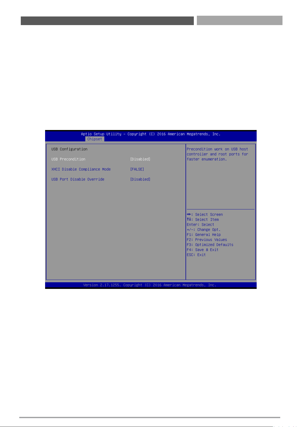
■ USB Configuration
USB Precondition[Disabled]
Precondition work on USB host controller and root ports for faster enumeration
Configuration options: [Disabled] [Enabled]
XHCI Disabled Compliance Mode [False]
Options to disable compliance mode.
Configuration options: [False][true]
USB Port Disable override [Disabled]
Selectively Enabled/Disabled the corresponding USB port from reporting a device connection to
the controller.
Configuration options: [Disabled] [Select Per-Pin]
Chapter 4: BIOS Setup
Page 62
CT-XSL01 | User’s Manual
62
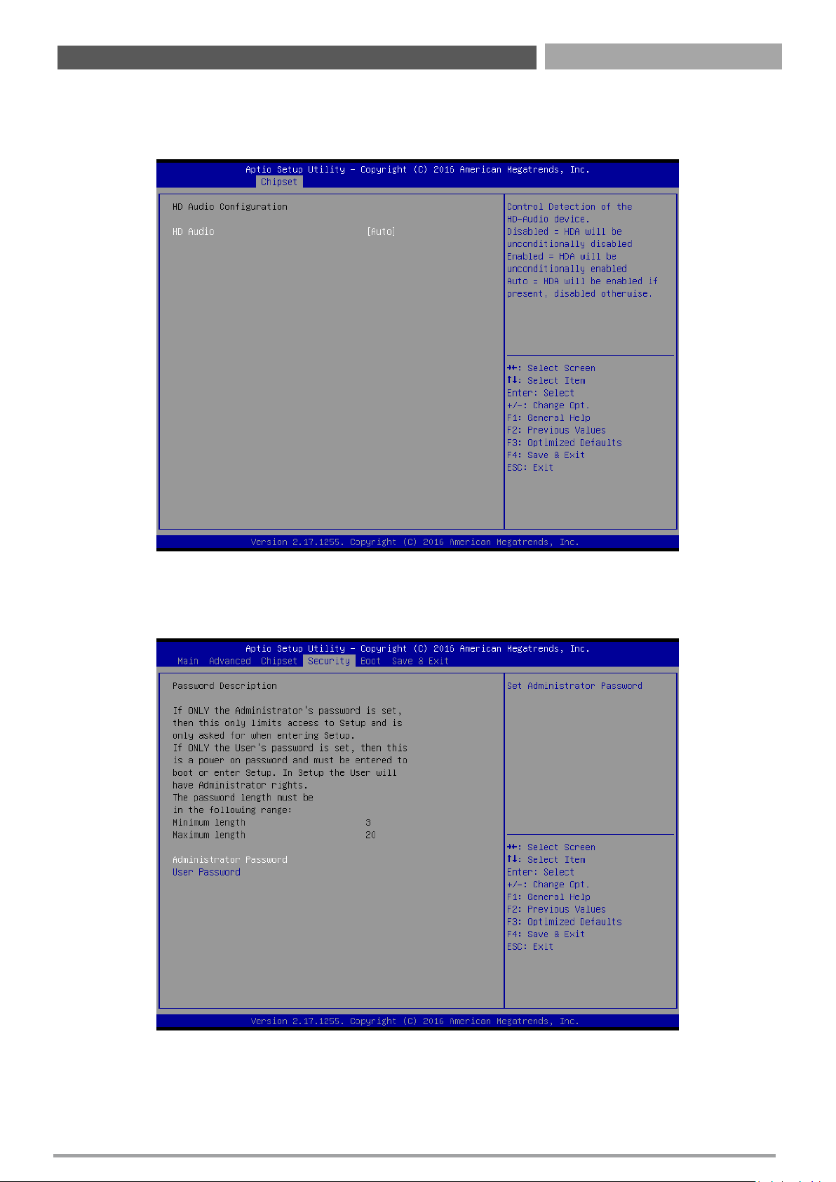
■ HD Audio Configuration
Control Detection of the HD-Audio device.
Configuration options: [Disabled] [Enabled][Auto]
4.5 Security
Security menu allow you to change administrator password and user password settings.
4.5.1 Administrator Password
This item allows you to set Administrator Password.
4.5.2 User Password
This item allows you to set User Password.
Chapter 4: BIOS Setup
Page 63
CT-XSL01 | User’s Manual
63
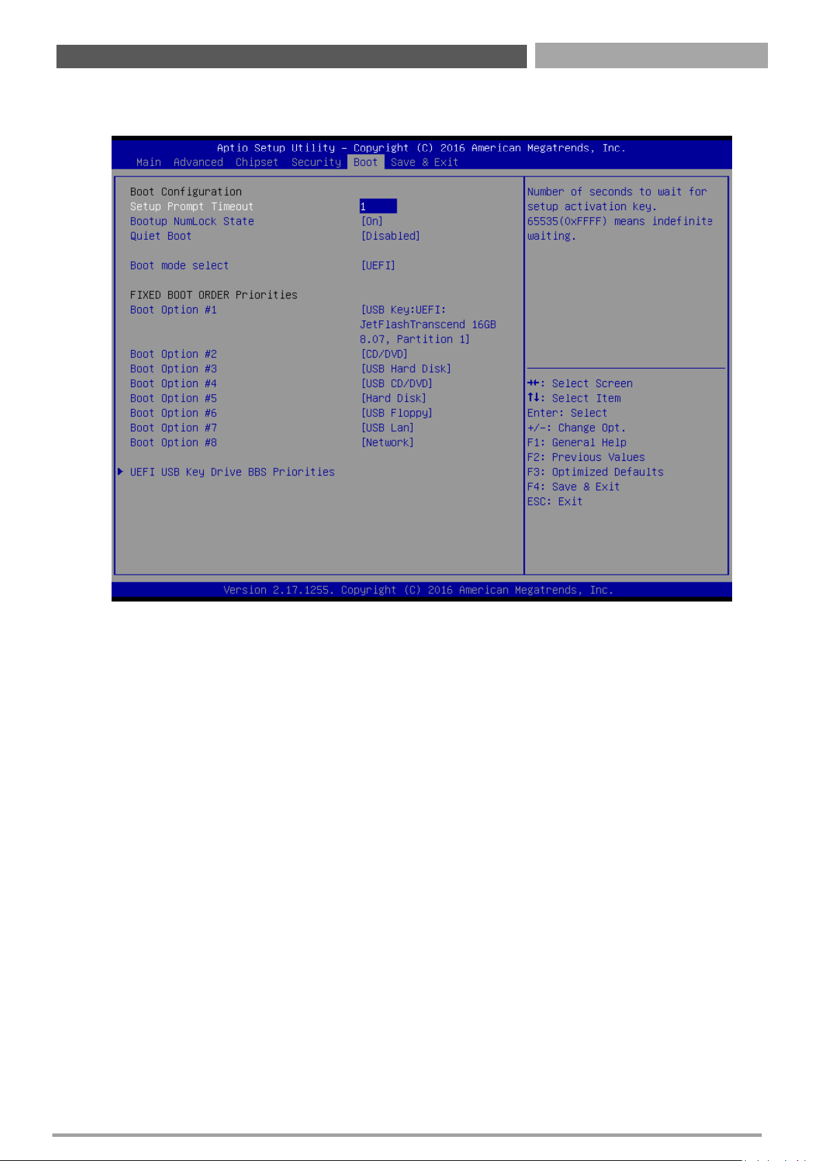
4.6 Boot
This menu allows you to setup the system boot options.
4.6.1 Setup Prompt Timeout
Number of seconds to wait for setup activation key. 65535(0xFFFF) means indefinite waiting.
4.6.2 Bootup NumLock State
This item selects the keyboard NumLock state. Select <On> or <Off>.
4.6.3 Quiet Boot
Enable or disable Quiet Boot option
Configuration options: [Disabled] [Enabled]
4.6.4 Boot mode select [UEFI]
Select boot mode LEGACY/UEFI
Configuration options: [LEGACY] [UEFI]
4.6.5 Boot Option Priorities
The items specify the boot device priority sequence from the available devices. The number of device
items that appears on the screen depends on the number of devices installed in the system.
4.6.6 UEFI USB Key Drive BBS Priorities
Specifies the boot device priority sequence from available UEFI USB key Drives.
Chapter 4: BIOS Setup
Page 64
CT-XSL01 | User’s Manual
64
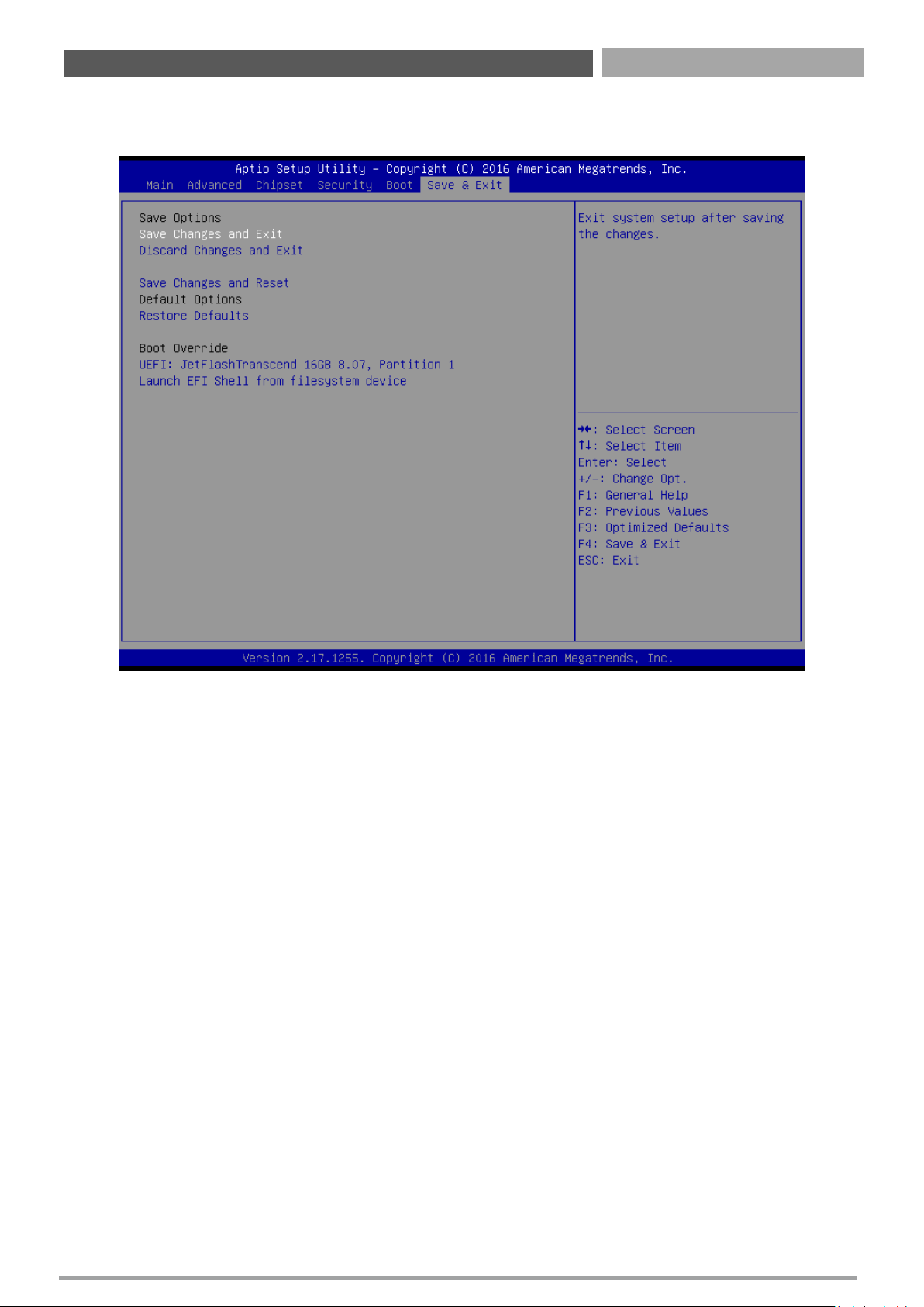
4.7 Save & Exit
This setting allows you to configure the boot settings.
4.7.1 Save Changes and Exit
This item allows you exit BIOS Setup after saving the changes.
4.7.2 Discard Changes and Exit
Select this option to quit Setup without making any permanent changes to the system configuration.
4.7.3 Save Changes and Reset
This item allows you reset the system after saving the changes.
4.7.4 Restore Defaults
This selection allows you to reload the BIOS when problem occurs during system booting sequence.
These configurations are factory settings optimized for this system.
4.7.5 Launch EFI Shell from Filesystem Device
Attempts to launch EFI shell application from one of the available filesystem devices.
Chapter 4: BIOS Setup
Page 65

Copyright © Premio Inc. All Rights Reserved
www.premioinc.com
 Loading...