

Premiertek HRU-221P3, HR-221P3 User Manual
1
AALLLL--IINN--OONNEE IINNTTEERRNNAALL CCAARRDD RREEAADDEERR//WWRRIITTEERR
USER MANUAL
(Rev.:1.0 )
INDEX
z Trademarks ----------------------------------------------------------------------
z Introductions --------------------------------------------------------------------
z Package contents ------------------------------------------------------------------
z Hardware requirements ------------------------------------------------------
z System Support -----------------------------------------------------------------
z How to install your card reader to a drive bay ---------------------------
z Pin assignment of USB cable -------------------------------------------------
z Media icon driver installation -----------------------------------------------
Windows
®
XP example -------------------------------------------------------
z How to load a media memory card -------------------------------------------
z Indicator description ----------------------------------------------------------
z USB port ----------------------------------------------------------------------------
z How to swap your front bezel ------------------------------------------------
z Product specifications -----------------------------------------------------------
z Notice for user application ------------------------------------------------------
2
2
2
2
2
2
3
4
4
7
9
9
10
10
11
2
Trademarks
All names and products mentioned below are registered trademarks of their respective companies.
Introductions
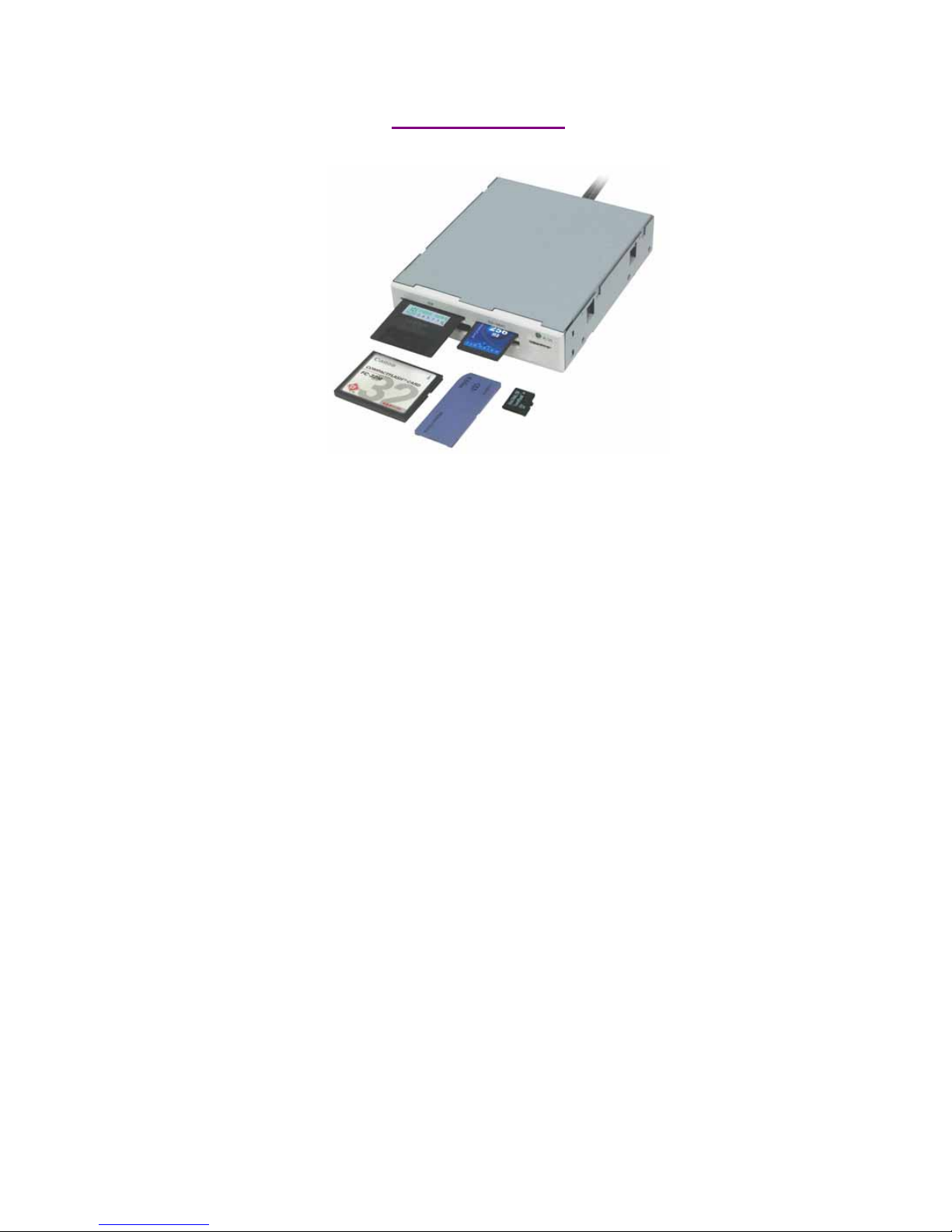
The All-in-1 internal Card Reader is ideal for 3.5 or 5.25inch drive bay installation. It is the best
solution for direct access to media cards in front of your computer.
The five media slots can support over twenty types of media cards, providing the advantages of
multiple card readers. The Card Reader directly accepts even the most popular small form-factor
flash cards such as Mini-SD, RS-MMC, MS-Duo and small T-flash, Micro SD, you can use them
without requiring any adapter. The card reader also supports standard media memory cards such as
Secure Digital card (SD), Multi Media card (MMC), Compact Flash™ (CF), IBM® Microdrive,
Smart Media™ (SM), Memory stick (MS), Memory stick pro, xD picture card and other compatible
memory cards.
Package contents
• Internal card reader
• Driver disc with manual
• Installing Screws
Hardware requirements
zIBM
®
PC computer with one available 3.5 or 5.25inch drive bay.
zOne dual USB2.0 on board host connector or USB host connector.
z5.25” carrier (optional item) will require when you install in 5.25” bay.
System Support
zWindows
®
98/SE, Windows®2000, Windows® ME, Windows® XP.
zLinux OS kernel versions 2.4.x or later.
How to Install Your Card Reader to a drive Bay
---------------------------------------------------------------------------------------------------------------------
CAUTION:
z Electrostatic discharge can damaged electronic components. Be sure you are properly grounded
before moving into next step.
z You can touch any metal parts of the computer’s chassis or power supply unit to discharge any static
charge that may have built up inside your body.
-----------------------------------------------------------------------------------------------------------------------
1. Turn your computer off and disconnect the power cord.
2. Remove the cover of your computer. (Refer to your computer’s
hardware reference manual and follow the instructions about
removing the cover)
3. Remove 3.5 or 5.25inch plastic cover on your PC’s front panel.
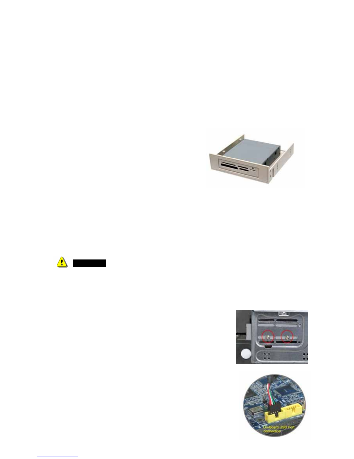
4. Put the internal card reader with USB cable into the drive bay.
5. Mount card reader firmly into drive carrier by four ISO 3φ*4mm
screws supplied in screw pack. (Refer to the illustration).
6. If your USB interface is a pin housing connector, please connect
USB cable end to your on-board USB connector that is a standard
ten male pin-header on your motherboard. (Please refer to following
USB pin assignment description and check your computer’s
on-board pin assignment that is the same definition. You can refer to
your computer’s hardware reference manual.)
3
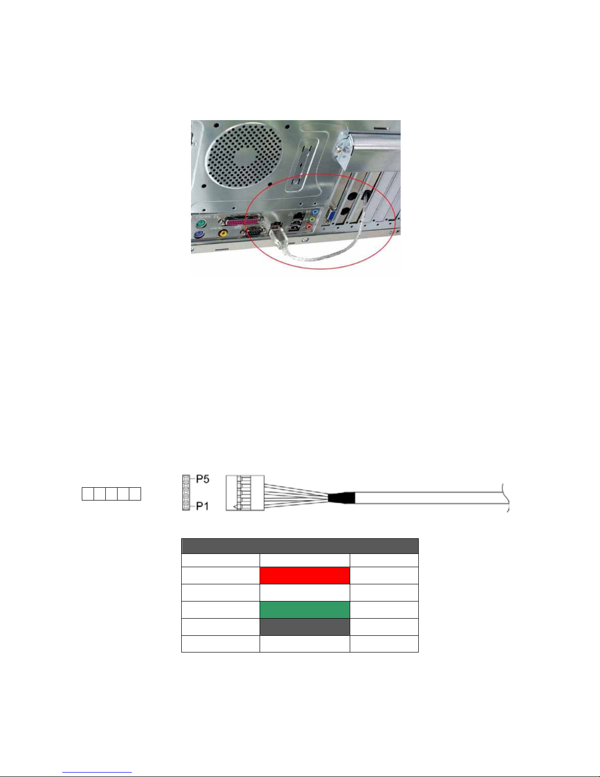
7. If your USB interface is an USB A-type plug, please replace a free PCI slot’s metal cover and
connect USB plug to an external USB port via the PCI slot. (Refer to the following illustration)
8. Check every connection is correct and do not leave any tools or screws inside of your computer
before you close the cover.
9. Replace your power cord and restart your computer.
Pin assignment of USB cable
Please read the following pin assignment descriptions carefully, it would help you how to connect
cable to your onboard USB connector correctly.
5-Pin USB cable housing pin assignment: (Apply to Model HR-221P3)
Single-row USB cable pin assignment
5 Pin Housing Wire color Assignment
P1 RED VBUS
P2 WHITE DP3 GREEN D+
P4 BLACK/ Shield GND
P5 NC NC
① ② ③ ④ ⑤
4
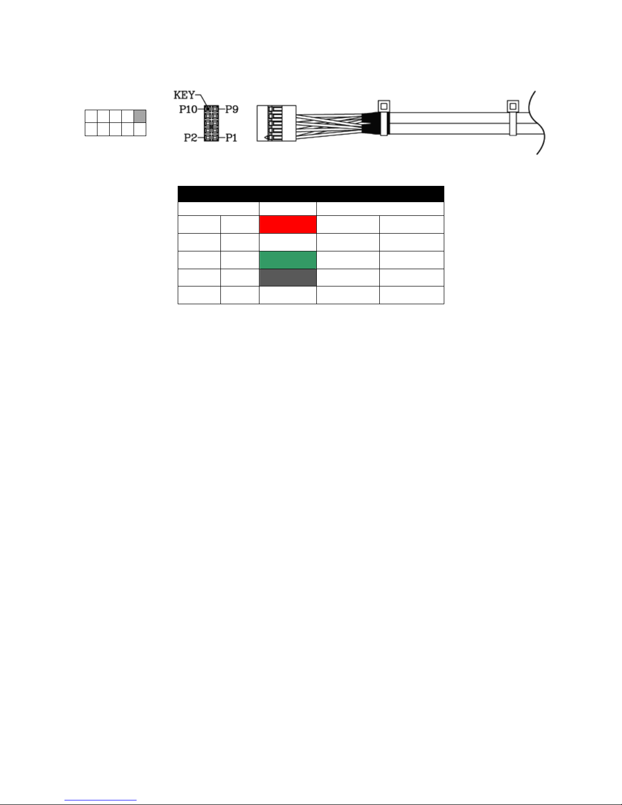
Dual-row USB cable housing Pin assignment: (Apply to Model HRU-221P3)
Dual USB cable pin assignment
2*5 Pin Housing Wire color Assignment
P1 P2 RED VBus VBus
P3 P4 WHITE D- DP5 P6 GREEN D+ D+
P7 P8 BLACK GND GND
P9 P10 Shield -
KEY
Note: The USB housing pin1 marks with symbol “”.
Media icon driver installation
For easy recognizing media icon on your computer, you need to install an application driver for all
Windows platforms to enable the media icons, you can find the software program in bundle disc and
follow the next example steps to complete the driver installation.
Windows® XP example:
1. Close all of your exist executing file.
2. Insert driver disc into the CD-ROM drive.
3. Double click on ” Driver” folder.
4. Double click on ” setup” icon.
5. Click “Next” button to begin software installing.
② ④ ⑥ ⑧ ⑩
① ③ ⑤ ⑦ ⑨
 Loading...