

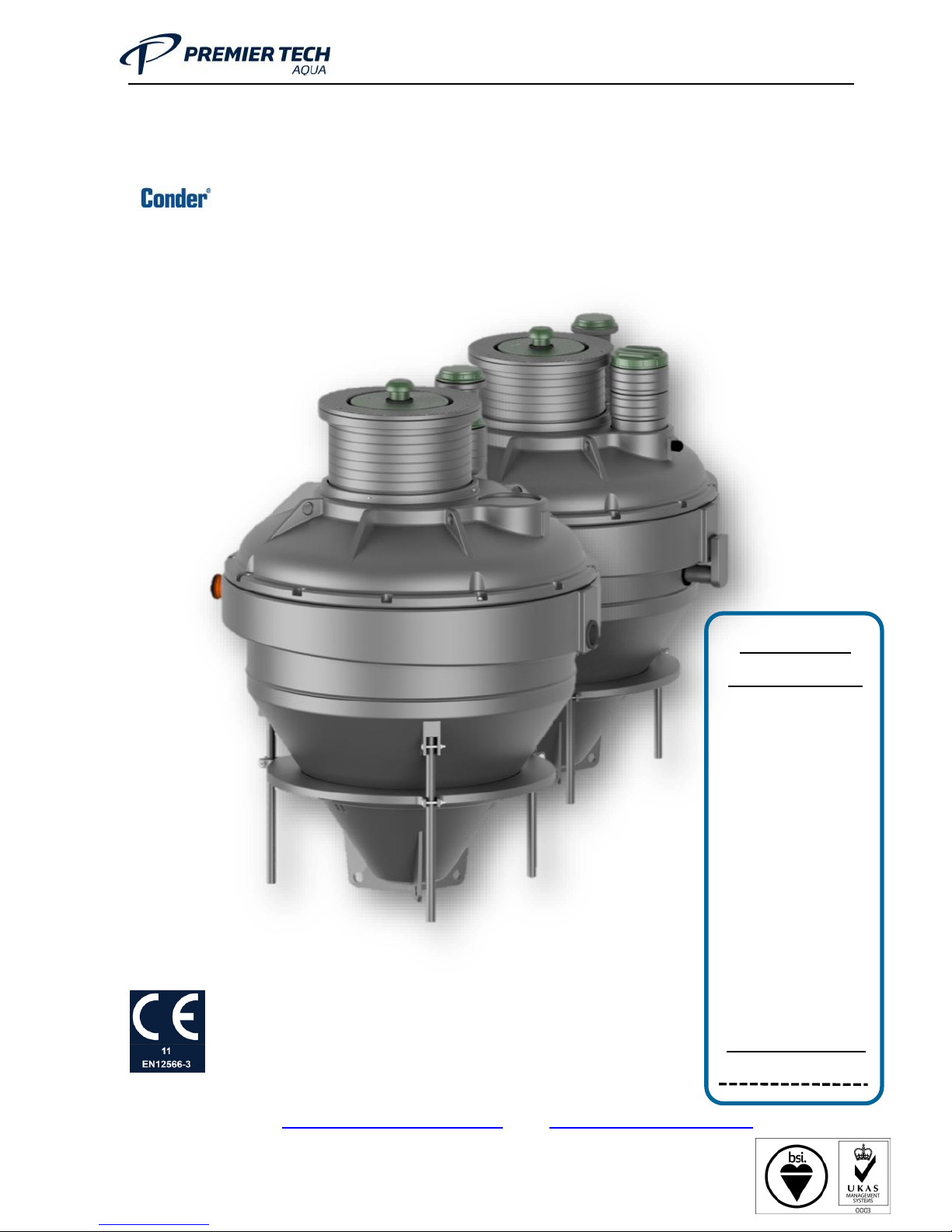
Premier Tech Aqua Conder ASP Series, ASP06P, ASP08, ASP08P, ASP12 Installation, Operation And Maintenance Manual
...Page 1
OM0006 Conder ASP HDPE Rev 5.2
1
Installation, Operation, and Maintenance Manual
for
ASP HDPE Package Sewage Treatment Plants
Standard Discharge Level:
20BOD/30SS/20NH3-N
Prem ier Tech Aqua Ltd
2 W hitehouse Way
S o uth West Industrial Estate
P eterlee, County Durham,
SR8 2RA
Tel : +44 (0) 8702 640004, Fax: +44 (0) 8702 640005
Ema il: [email protected], Web:www.premiertechaqua.co.uk
136249
Unit Installed
(please tick):
ASP06 ASP06P
ASP08 ASP08P
ASP12 ASP12P
ASP16 ASP16P
ASP20 ASP20P
ASP25 ASP25P
Serial number
Page 2
OM0006 Conder ASP HDPE Rev 5.2
2
•
•
•
Page 3
OM0006 Conder ASP HDPE Rev 5.2
3
•
•
Table of Contents
2
5
7
7
8
’ 9
– 10
– 12
– 14
15
16
18
20
21
35
36
36
37
Page 4
OM0006 Conder ASP HDPE Rev 5.2
4
38
39
40
43
44
51
’ ’ 53
60
61
62
63
64
66
Page 5
OM0006 Conder ASP HDPE Rev 5.2
5
•
•
•
•
•
•
Page 6
OM0006 Conder ASP HDPE Rev 5.2
6
•
•
•
Page 7

OM0006 Conder ASP HDPE Rev 5.2
7
Page 8
OM0006 Conder ASP HDPE Rev 5.2
8
•
•
Page 9
OM0006 Conder ASP HDPE Rev 5.2
9
’
Page 10
OM0006 Conder ASP HDPE Rev 5.2
10
–
Page 11

OM0006 Conder ASP HDPE Rev 5.2
11
Page 12

OM0006 Conder ASP HDPE Rev 5.2
12
–
Page 13

OM0006 Conder ASP HDPE Rev 5.2
13
Page 14
OM0006 Conder ASP HDPE Rev 5.2
14
–
Page 15
OM0006 Conder ASP HDPE Rev 5.2
15
Page 16
OM0006 Conder ASP HDPE Rev 5.2
16
Page 17

OM0006 Conder ASP HDPE Rev 5.2
17
”
Page 18
OM0006 Conder ASP HDPE Rev 5.2
18
•
Page 19

OM0006 Conder ASP HDPE Rev 5.2
19
Page 20
OM0006 Conder ASP HDPE Rev 5.2
20
Page 21
OM0006 Conder ASP HDPE Rev 5.2
21
’
Page 22
OM0006 Conder ASP HDPE Rev 5.2
22
–
–
’
–
–
Page 23
OM0006 Conder ASP HDPE Rev 5.2
23
Page 24
OM0006 Conder ASP HDPE Rev 5.2
24
–
Page 25
OM0006 Conder ASP HDPE Rev 5.2
25
7.
Integrated blower ventilation
Air inlets
Page 26
OM0006 Conder ASP HDPE Rev 5.2
26
Page 27
OM0006 Conder ASP HDPE Rev 5.2
27
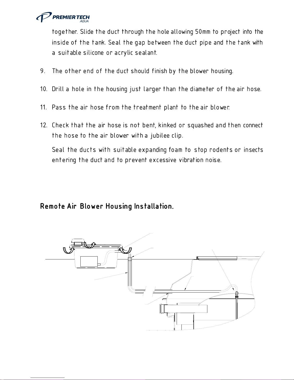
13.
HOSETAI
AIR HOSE
HOLE IN HOUSING
FOR AIR HOSE
AIR INLET
AIR INLET
AIR OUTLET
CUT HOLE FOR DUCT
AND SEAL AFTER
DUCT
(MIN.50mm)
GROUND LEVEL
BLOWER
FIX WITH JUBILEE
CLIP ONTO
BRASS FITTING
GROUND LEVEL
SEAL WITH
EXPANDED FOAM
Page 28
OM0006 Conder ASP HDPE Rev 5.2
28
Page 29
OM0006 Conder ASP HDPE Rev 5.2
29
Page 30
OM0006 Conder ASP HDPE Rev 5.2
30
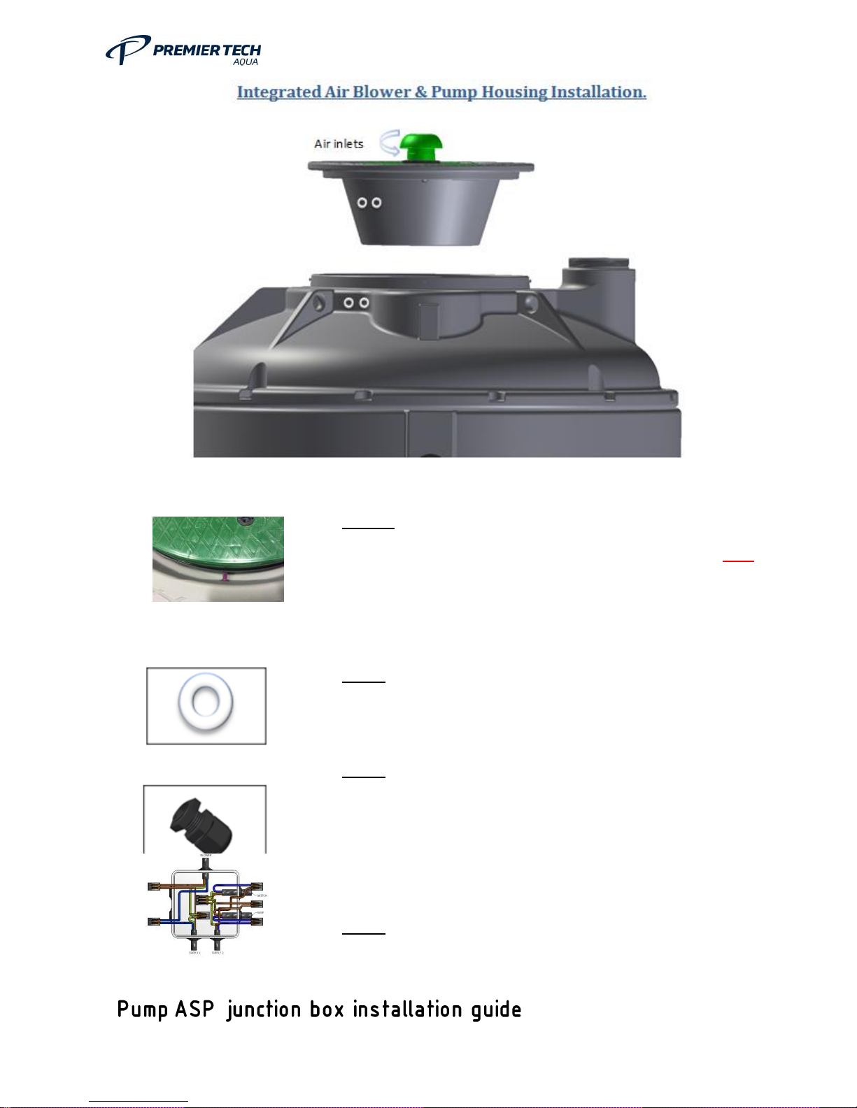
STEP 1
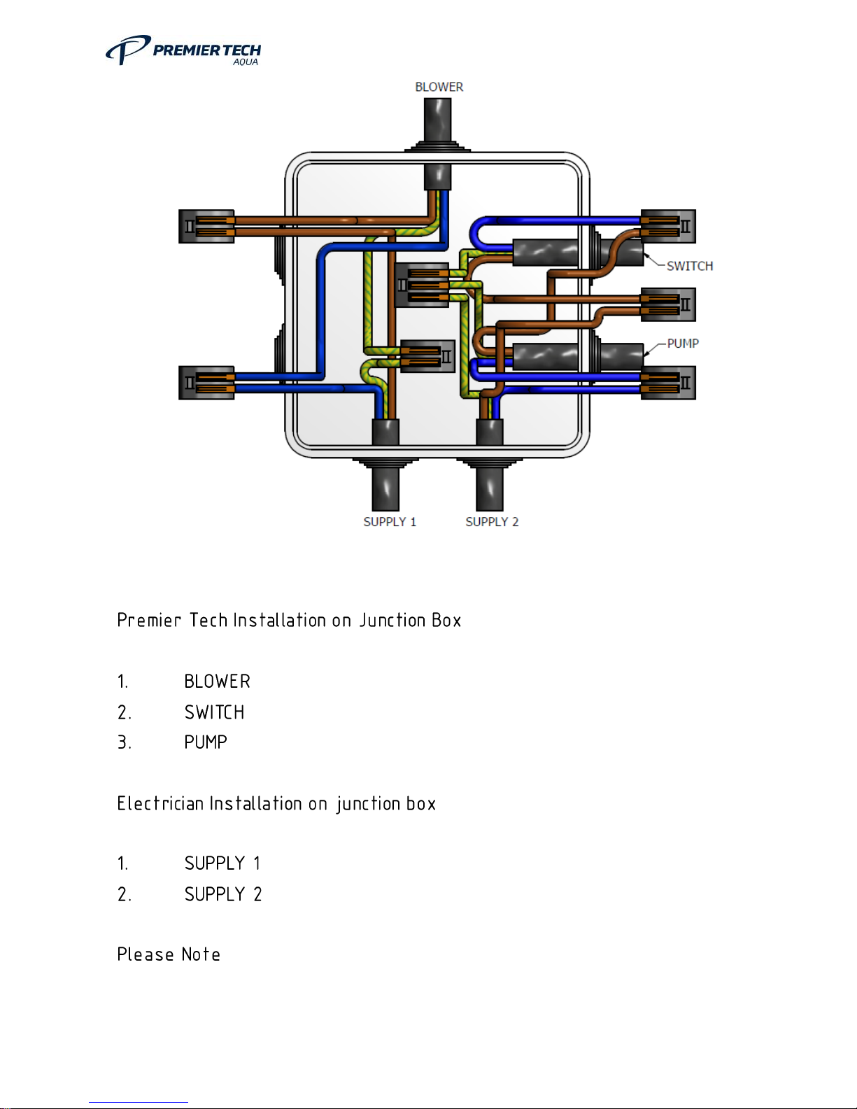
When Plant arrives, it is fitted with rubber plug. This plug Must
be removed before operating
STEP 2 - Drill 2 holes for supply 1 and 2 (on Main lid & Blower
box) Diameter to suit cable gland accordingly
STEP 3 - Fit Cable Gland for supply 1 and 2 on Main lid and
blower box showing in the picture above making sure this is fully
sealed. (Allowing cable to fit through main lid and inside blower
box where the junction box is situated. (Glands NOT supplied)
STEP 4 - Qualified Electrician to connect as instructed in O&M
Page 31
OM0006 Conder ASP HDPE Rev 5.2
31
Page 32
OM0006 Conder ASP HDPE Rev 5.2
32
Page 33
OM0006 Conder ASP HDPE Rev 5.2
33
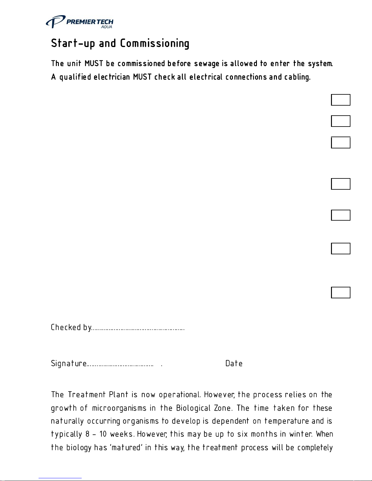
Check that the air line from the air blow er to the plant is unobstructed
Ensure there are no dirt or materials in the tank
Ensure the unit is f illed w ith clean w ater and there is a discharge from the outlet.
This is best done by using a hosepipe in the inlet manhole or by running several taps
in the connected household(s)
Check the electrical supply has been installed by a qualified electrician
Sw itch the Blow er Isolator to ON. Check the air blow er runs. Check the aeration
pattern in the bio-zone
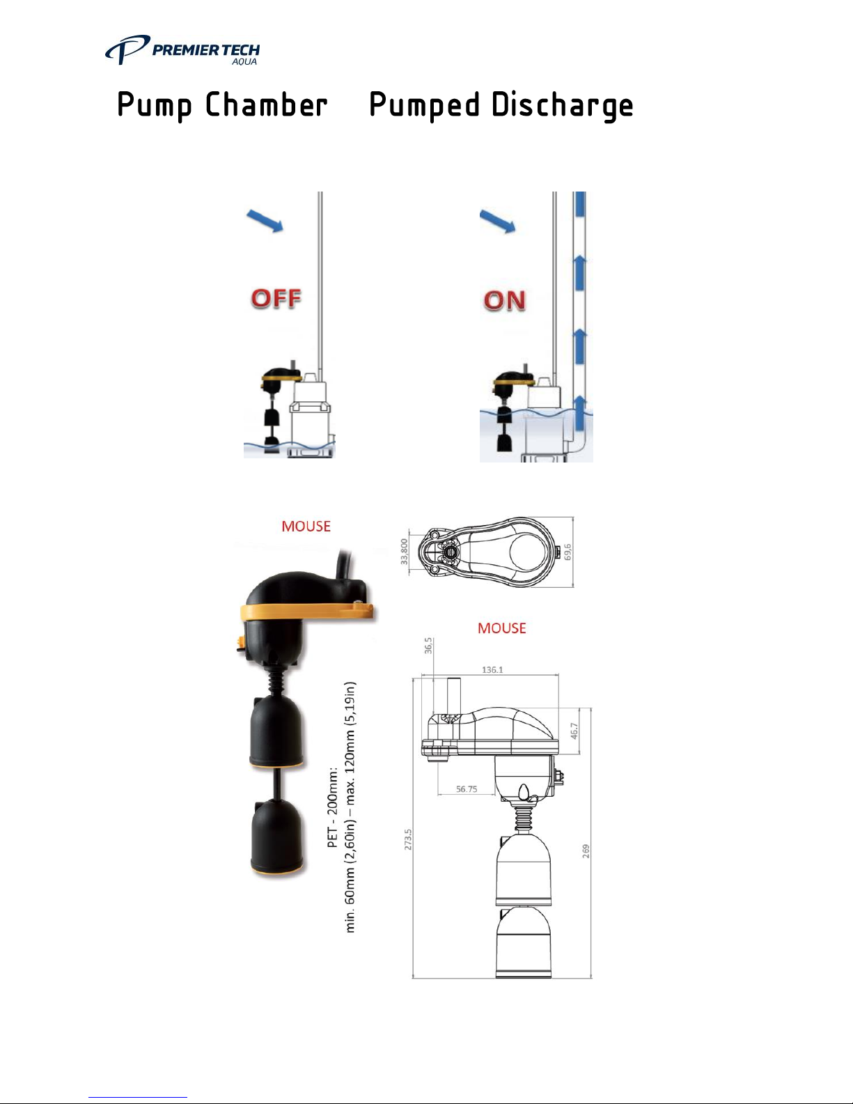
Where f itted, check that the outlet pump integral float sw itch can move freely. Ensure
there is sufficient w ater in the pump chamber f or the pump to operate i.e. the pump
float is raised
Sw itch the Pump (w hen applicable) Isolator to ON. Check that the pump operates.
The level in the pump chamber should drop until the float sw itch stops the pump
…… …………………
Page 34
OM0006 Conder ASP HDPE Rev 5.2
34
•
•
•
•
Page 35
OM0006 Conder ASP HDPE Rev 5.2
35
Page 36
OM0006 Conder ASP HDPE Rev 5.2
36
•
•
•
•
•
•
•
•
Page 37
OM0006 Conder ASP HDPE Rev 5.2
37
•
• Obtain a sample of the final effluent to check that the plant is operating correctly. This may
require introducing a small flow into the treatment unit to obtain the sample.
•
•
•
•
•
•
•
’
•
•
Page 38
OM0006 Conder ASP HDPE Rev 5.2
38
•
•
•
•
•
•
•
•
’
Page 39
OM0006 Conder ASP HDPE Rev 5.2
39
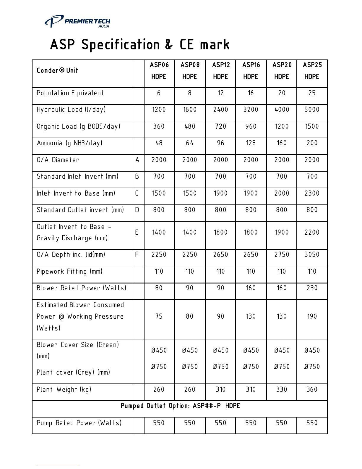
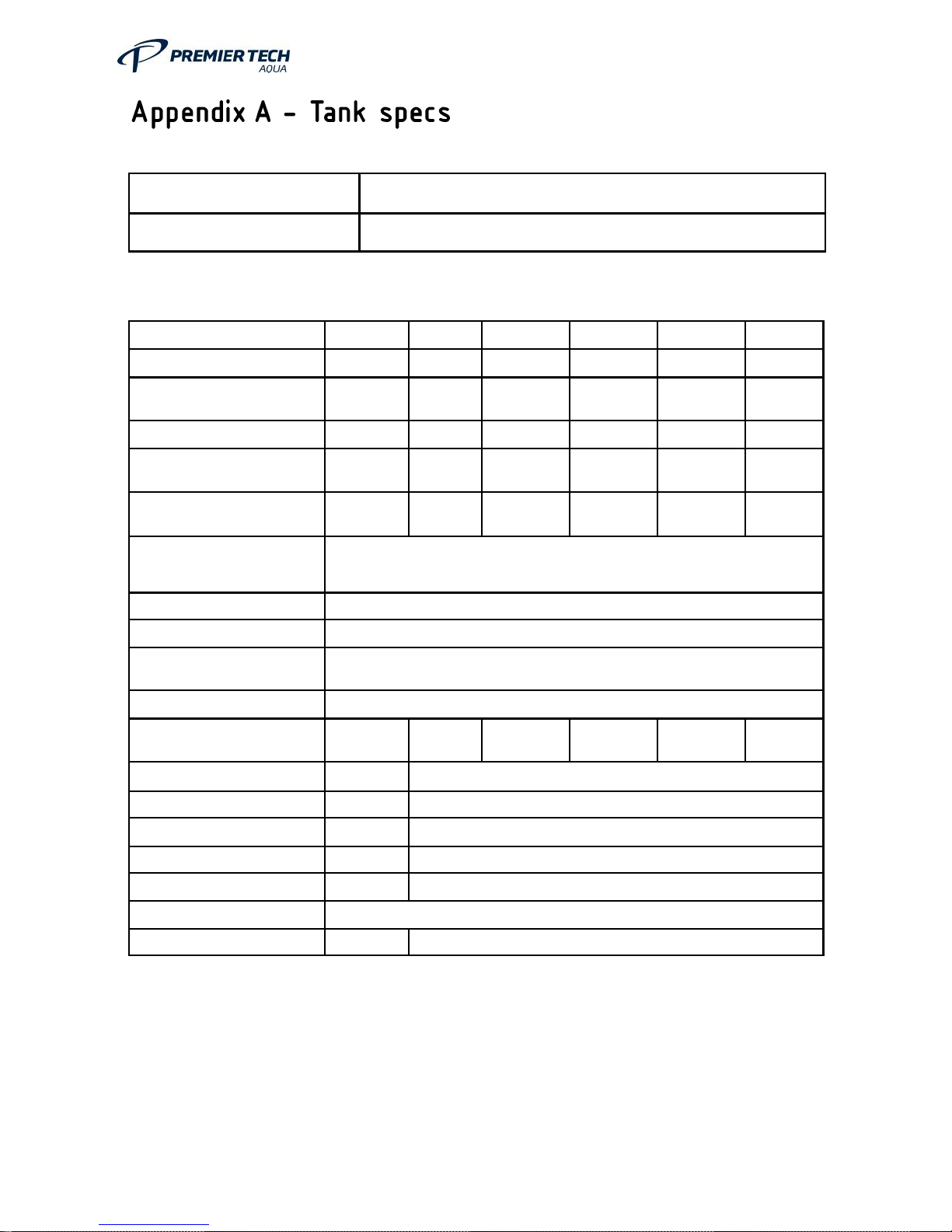
ASP06
ASP08
ASP12
ASP16
ASP20
ASP25
Design Loadings (max.)
Population Equiv alent
[P.E.]
6 8 12
16
20
25
Hydraulic Load [l/day ]
1200
1600
2400
3200
4000
5000
Organic Load
[g BOD/day ]
360
480
720
960
1200
1500
Ammonia Load
[g NH3/d]
48
64
96
128
160
200
Dimensions
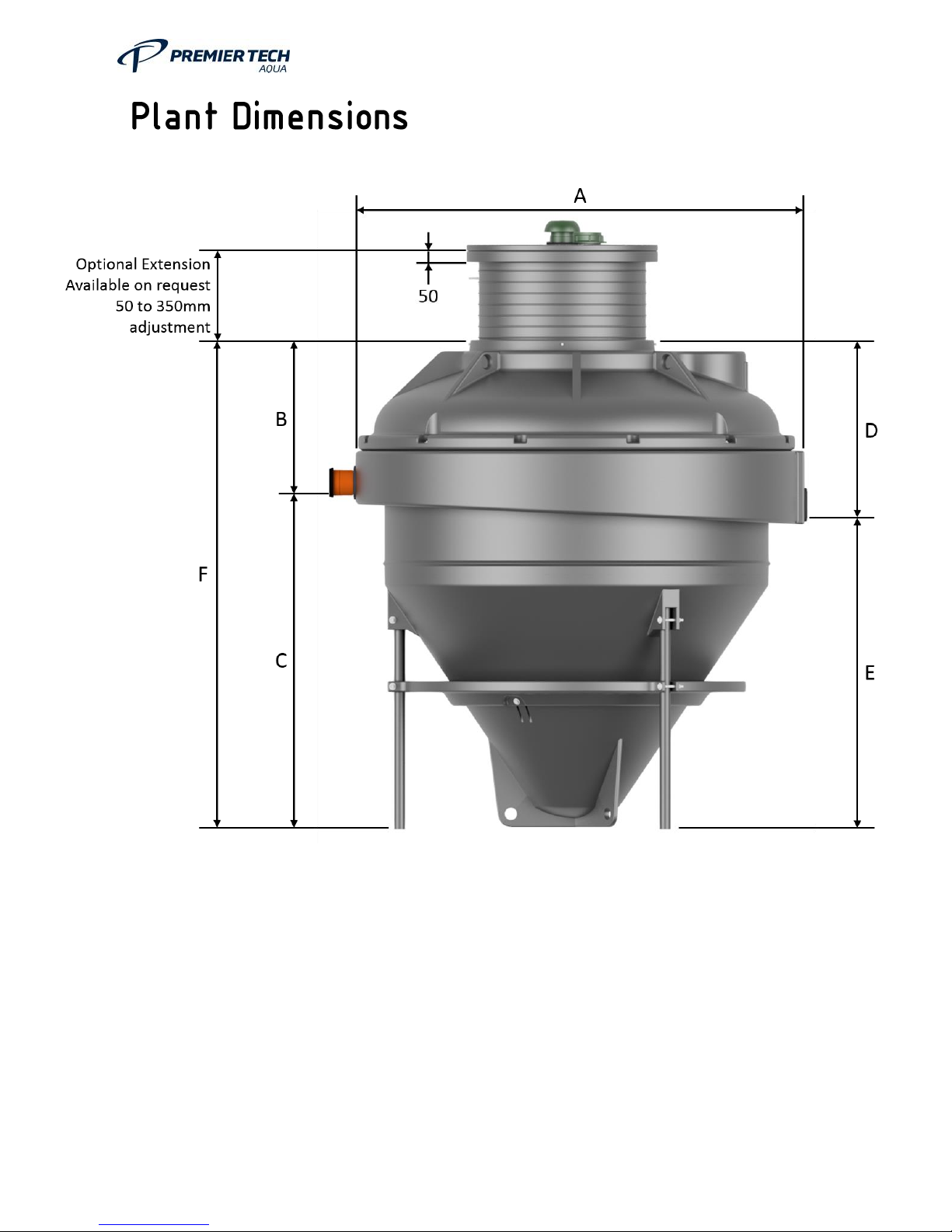
See page 12 for dimensions
Drain Inlet Invert [m]
See page 12 for dimensions
Depth from Inlet Invert
[m]
See page 12 for dimensions
Pipew ork Connections
110 Socket inlet / 110 rubber grommet outlet
Approx imate Weight
(empty ) [kg]
260
260
310
310
330
360
Blower
Pow er consumption
See page 12 for details
Pow er Supply
Single Phase, 240V, 50Hz
Pum p
Pow er consumption
See page 12 for details
Pow er Supply
Single Phase, 240V, 50Hz
Material Specification:
High Density Polyethylene.
Colour:
Natural Grey
Page 40
OM0006 Conder ASP HDPE Rev 5.2
40
Page 41
OM0006 Conder ASP HDPE Rev 5.2
41
Page 42
OM0006 Conder ASP HDPE Rev 5.2
42
Page 43
OM0006 Conder ASP HDPE Rev 5.2
43
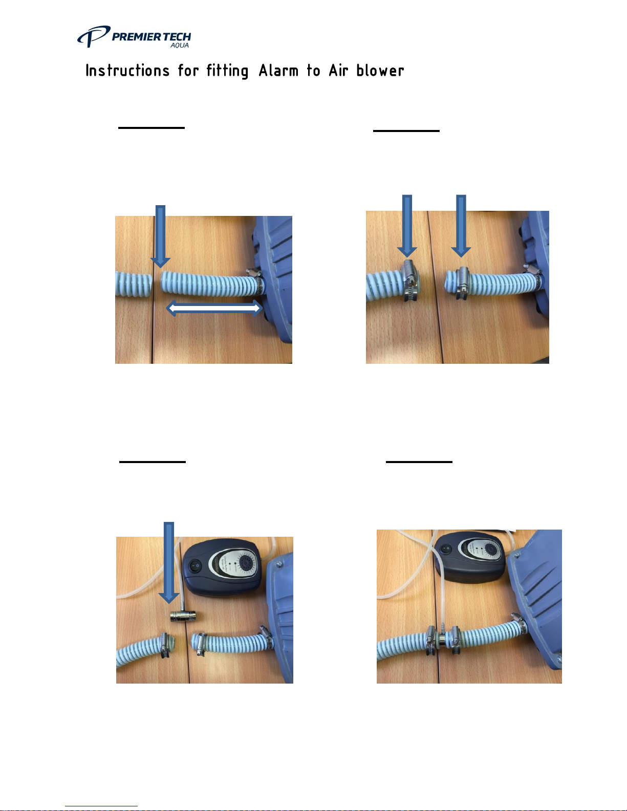
STEP 1
Cut hose approximately 100mm
from blower
STEP 2
Place Jubilee clips over hose
STEP 3
Place T-piece in the middle of the
hose pipe
STEP 4
Tighten all Jubilee clips up
securely
Page 44
OM0006 Conder ASP HDPE Rev 5.2
44
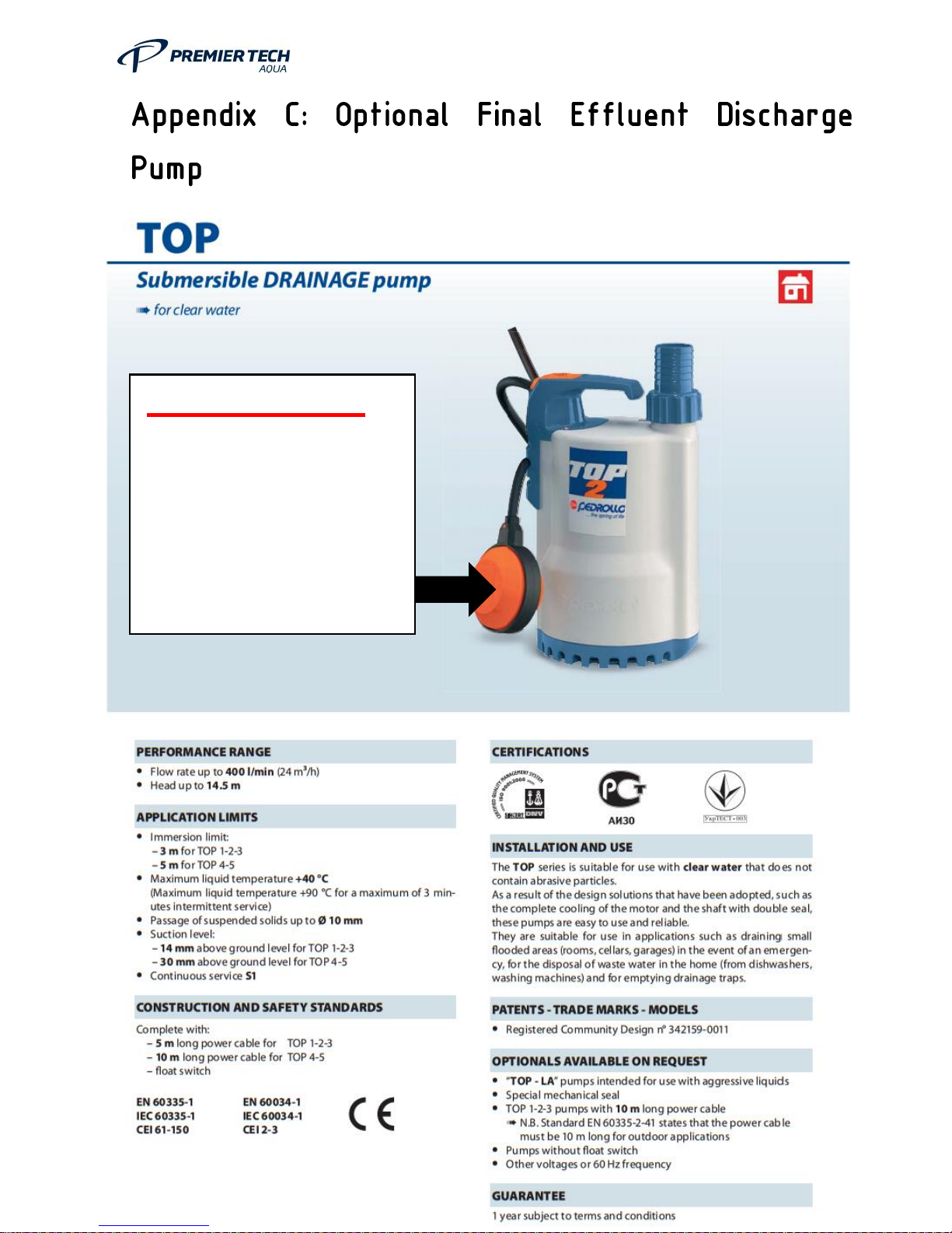
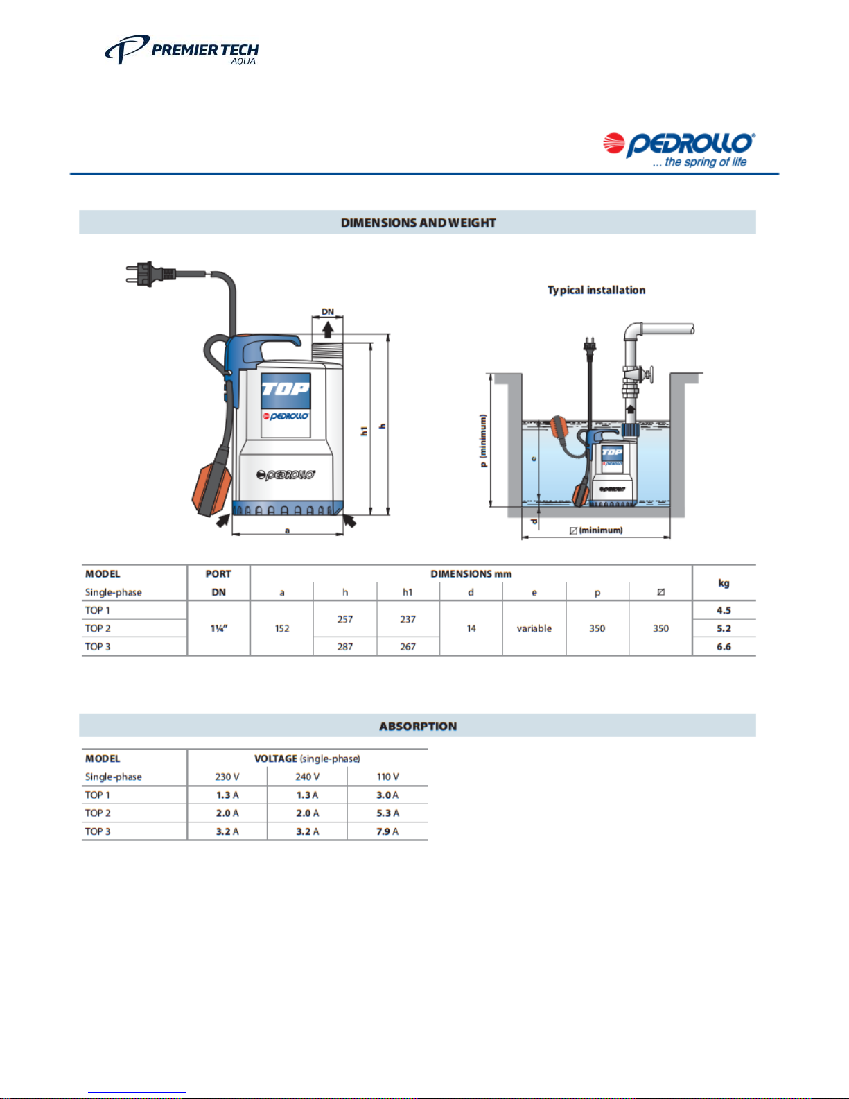
PLEASE NOTE:
Round Float will NOT be
fitted to top 2 pump.
Vertical Switch will be fitted
(See Page 10&11 for details)
Page 45
OM0006 Conder ASP HDPE Rev 5.2
45
Page 46
OM0006 Conder ASP HDPE Rev 5.2
46
Page 47
OM0006 Conder ASP HDPE Rev 5.2
47
Page 48
OM0006 Conder ASP HDPE Rev 5.2
48
“ ”
Page 49
OM0006 Conder ASP HDPE Rev 5.2
49
Page 50

OM0006 Conder ASP HDPE Rev 5.2
50
Page 51
OM0006 Conder ASP HDPE Rev 5.2
51
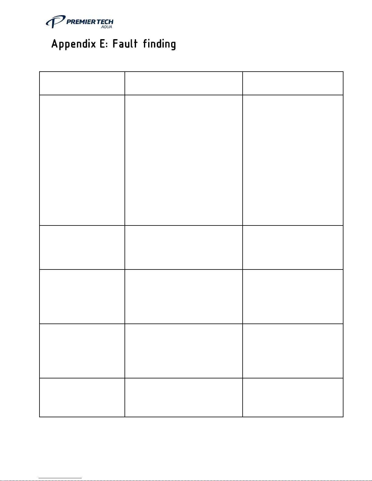
Symptom
Cause
Action
Strong Odour
Excess chemicals in the plant
Excessive laundry use
Carry out a settlement test
Drains inadequately venting
Nothing obvious can be found
Lack of aeration
See appendix F
See appendix F
See appendix D
Check that a high level vent is
fitted to the house and is
working correctly.
Carryout 12month service and
correct any faults found.
Check air blower.
Air blower stopped
Switched off at the mains isolator
Power Failure
Switch on
Check the supply board for a
trip or fuse.
Air blower is running
but no turbulence
Air pipe has been blocked or
squashed or has a problem such as
the hose is split
Air blower diaphragm split
Inspect pipe and check all
joints for any leaks or splits.
Replace air blower diaphragm.
Poor final effluent
Check the air blower is operating
and delivering air to the bio-zone
Carry out a settlement test in
appendix D
Check and repair any faulty
parts.
Follow the fault finding guide in
appendix E.
Bio-zone chamber has
grey colour
Check there is good supply of air to
the plant(turbulent pattern in Bio-
zone).
Check air blower is operating
correctly.
Page 52
OM0006 Conder ASP HDPE Rev 5.2
52
Symptom
Cause
Action
Bio-zone has greyish to
black colour and an
offensive odour
Excessive laundry use
See do & don’ts section of this
manual re laundry detergents.
Bio-zone has a very
light brown colour and
has few suspended
solids. White suds.
Lightly loaded
If plant has just started or the
effluent quality is OK, no
further action. Otherwise
contact Premier Tech Aqua for
advice.
Check that no surface water is
entering the plant.
Bio-zone is black in
appearance
Plant is organically over-loaded
Not enough air is getting to the biozone
Check load to plant or if a desludge is required.
Check air blower and air lines.
Grease particles in the
bio-zone.
Too much grease in effluent.
Excessive laundry use
Reduce grease in kitchen
waste.
See laundry section of do &
Don’ts.
Final effluent contains
many Solids.
Carry out 12-month service
Only empty the plant of sludge
if required.
Final Effluent Discharge
Pump not running
Switched off at the mains isolator
Power Failure
Switch on.
Check the supply board for a
trip or fuse.
Final Effluent Discharge
Pump running but
effluent not being
pumped
Pump float switch jammed – no
effluent to pump in pump chamber
Debris blocking pump
Pump non return valve blocked
Isolate pump, remove and free
float switch.
Isolate pump, remove and
remove debris.
Isolate pump, remove pump
and free non return valve.
Page 53
OM0006 Conder ASP HDPE Rev 5.2
53
’ ’
n
Page 54
OM0006 Conder ASP HDPE Rev 5.2
54
Do:
•
•
Page 55
OM0006 Conder ASP HDPE Rev 5.2
55
Don't:
Page 56
OM0006 Conder ASP HDPE Rev 5.2
56
Page 57
OM0006 Conder ASP HDPE Rev 5.2
57
Page 58
OM0006 Conder ASP HDPE Rev 5.2
58
Page 59
OM0006 Conder ASP HDPE Rev 5.2
59
“ ”
Page 60
OM0006 Conder ASP HDPE Rev 5.2
60
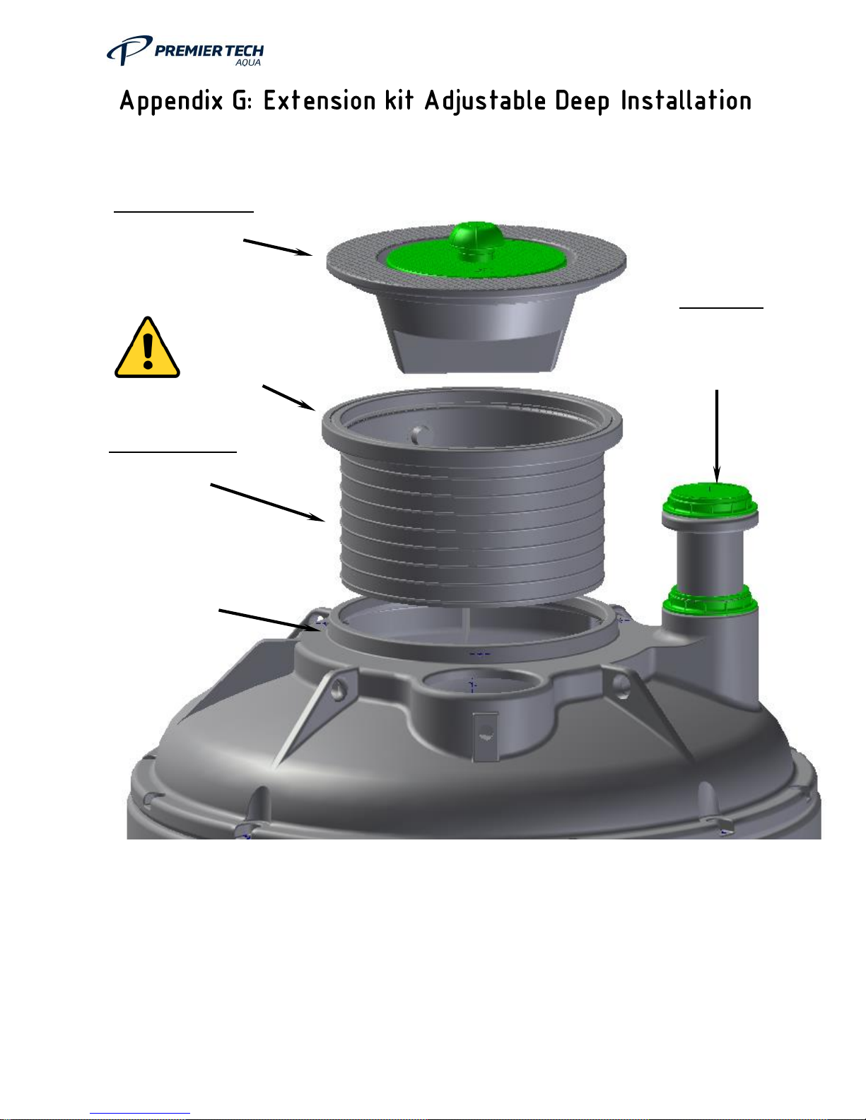
PLEASE NOTE:
Upon installation of the extension shaft please ensure extension shaft is fully
sealed to prevent backfill entering the system.
Blower container
To be fitted to the
extension.
.
Ground level
must not exceed
this level.
Extension Shaft
To be adjusted to
suit ground level.
Secure extension
to the ASP collar
with 70mm long
tek-screws x 4.
De-sludge
Extension to be
adjusted to suit
ground level.
Page 61
OM0006 Conder ASP HDPE Rev 5.2
61
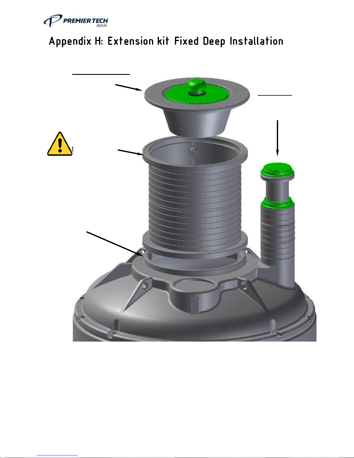
NOTE: With a fixed extension kit you can still have the neck adjustable to suit your
requirements by cutting off the bottom of the shaft, also adjust the de-sludge fitting to
suit ground level. After cutting the shaft please refer to APPENDIX G for installation
guide.
PLEASE NOTE: Upon installation of the extension shaft please ensure
extension shaft is fully sealed to prevent backfill entering the system.
Ground level
must not exceed
this. level
Secure
extension to the
ASP collar with
70mm long tek-
screws x 4.
Blower container
To be fitted to the
extension.
De-sludge
Extension to be
adjusted to suit
ground level.
Page 62

OM0006 Conder ASP HDPE Rev 5.2
62
Do:
Read this O&M Manual including appendices for full details
Keep this manual together with any drawings that were issued and any other
communication (order acknowledge, quotation, etc.)
Take care when offloading the unit – external and internal pipe work & electrical
equipment could be damaged!
Ensure adequate ventilation – the treatment plant is part of the foul drainage
system and requires venting (see section “Installation Instructions“, p. 10)
Use a suitable rated cable to connect the socket inside the Conder® ASP unit
to the electrical equipment (see “Electrical Installation “, p. 16)
Don’t:
Install any Conder® ASP units deeper than the supplied access turrets (i.e. do
not extend the turrets)
Incorporate a standard household earth leakage circuit breaker (RCD) in the
power supply to the unit, unless required by IEE regulations. Then a dedicated
device should be provided (see section “Electrical Installation “).
Important Warning:
The standard Tank is designed for an installation depth of up to 1 metres from
the Inlet Invert with a Water Table up to Grade when installed in a concrete
backfill and incorporating the manufacturers Deep Installation Extension Kit.
Failure to comply with these requirements will result in the invalidation of the
manufacturer’s warranty.
Page 63
OM0006 Conder ASP HDPE Rev 5.2
63
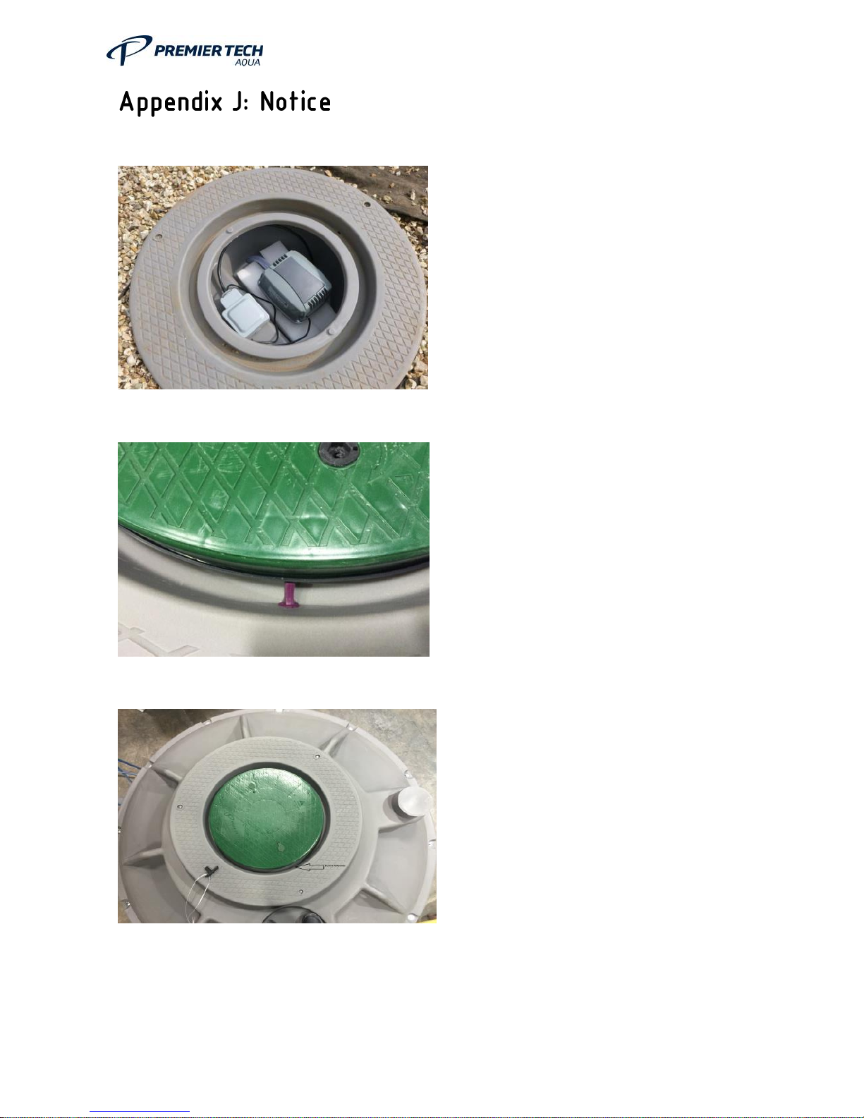
Please remove transport packaging
(Foam, Plastic Bag) before
operating this plant.
When the plant arrives, it is fitted
with a rubber plug. This Must be
removed before operating.
Rubber Plug is removed before
operation.
Page 64
OM0006 Conder ASP HDPE Rev 5.2
64
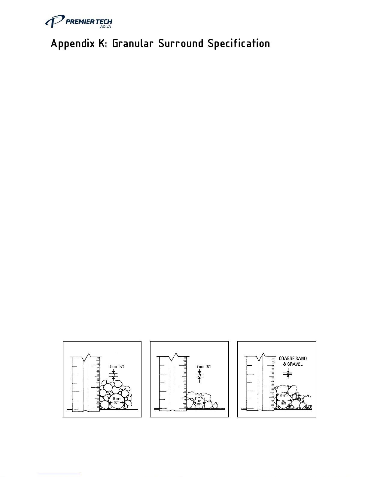
Pea Gravel
MUST be naturally rounded aggregate with a particle size greater than 3 mm
and less than 18mm.
Gravel MUST be clean and free flowing, free from large rocks, dirt, sand,
roots, organic materials or debris.
Upon screening analysis, the backfill material MUST have no more than 5% by
weight passing 2.38mm Sieve.
Crushed Stone
MUST be crushed stone or gravel with particle size not less than 3 mm and
not greater than 12 mm.
Aggregate MUST be clean and free flowing, free from large rocks, dirt, sand,
roots, organic materials or debris. Material MUST be washed or screened to
remove fine particles.
Upon screening analysis, the backfill material MUST have no more than 5% by
weight passing 2.38 mm Sieve.
Use of other than specified backfill and bedding materials will void the tank
warranty.
NOTE: All backfill material shall be free of ice and snow at time of installation.
Backfill material shall not be frozen or contain lumps of frozen material at any
time during placement.
Pea Gravel
Crushed Stone
Secondary Backfill
Page 65

OM0006 Conder ASP HDPE Rev 5.2
65
Secondary Backfill Specification
Secondary backfill shall not be used adjacent to the tank. It MUST only be used
only at 450mm from the tank walls. The following are approved as Secondary
Backfill materials:
Gravel
The Gravel MUST not contain any rocks larger than 36 mm on largest
dimension.
Backfill materials MUST be clean and free flowing, free from dirt, clay, fine sand,
roots, organic materials or debris.
Upon screening analysis, this backfill material MUST have no more than 5% by
weight passing through a 0.075mm Sieve.
During placement, this backfill material must be compacted to 95% Relative
Compaction.
Page 66

OM0006 Conder ASP HDPE Rev 5.2
66
Concrete Specification
The specification for the concrete mix to surround the tank should be selected
by the tank installer considering the site conditions and application
requirements.
For a typical non-structural application in good ground conditions, with non-
aggressive soils, a concrete with a 28-day compressive strength of 20 to
30N/mm2 with a 25 to 50mm slump, complying with the relevant BS EN, is
generally suitable. For non-typical applications, aggressive soils or structural
applications specialist advice should be obtained.
Lift height (rate of rise)
Determine the lift height (m), or rate of rise (m/h) for the specific concrete type
used, to ensure that a design pressure (P max) of 15kN/m2 on the tank IS NOT
exceeded.
Vibration
The design of the tank assumes minimal compaction of the surrounding
concrete. Where necessary, this may be extended to include light internal
vibration. Do not use deep re-vibration which will substantially increase the
pressure on the tank, possibly causing failure.
Impact of Concrete on Discharge
The effects of concrete discharge impact are considerable. These effects must
be considered to ensure the maximum pressure of 15kN/m2 on the tank is not
exceeded. UNDER NO CIRCUMSTANCES should concrete be discharged
directly onto the tank.
Live Load
If the tank is installed in an area where traffic, or other superimposed loadings
can be applied, a structural engineer should be consulted, to design a reinforced
concrete slab spanning over the tank. This is to prevent the load being
transmitted to the tank (or its concrete surround). If this slab is constructed
immediately above the tank, it should be separated from the concrete
surrounding the tank by compressible material.
Page 67

OM0006 Conder ASP HDPE Rev 5.2
67
Control of Groundwater
Tanks must not be subjected to buoyant forces during installation, taking
account of ground water levels and surface water run-off, and their accumulation
in the tank excavation.
Installation Procedure
Maintain a completely dry excavation until the final pour of concrete has set.
Failure to do this may result in voids beneath the tank.
Fill the tank with clean water to a depth of 300mm and recheck the pipework
levels and connections. Commence backfilling evenly around the tank with
concrete ensuring there are no voids. Continue filling the tank with water whilst
evenly backfilling with concrete around the tank ensuring that the progressive
water level is no more than 300mm above the concrete level.
Page 68
OM0006 Conder ASP HDPE Rev 5.2
68
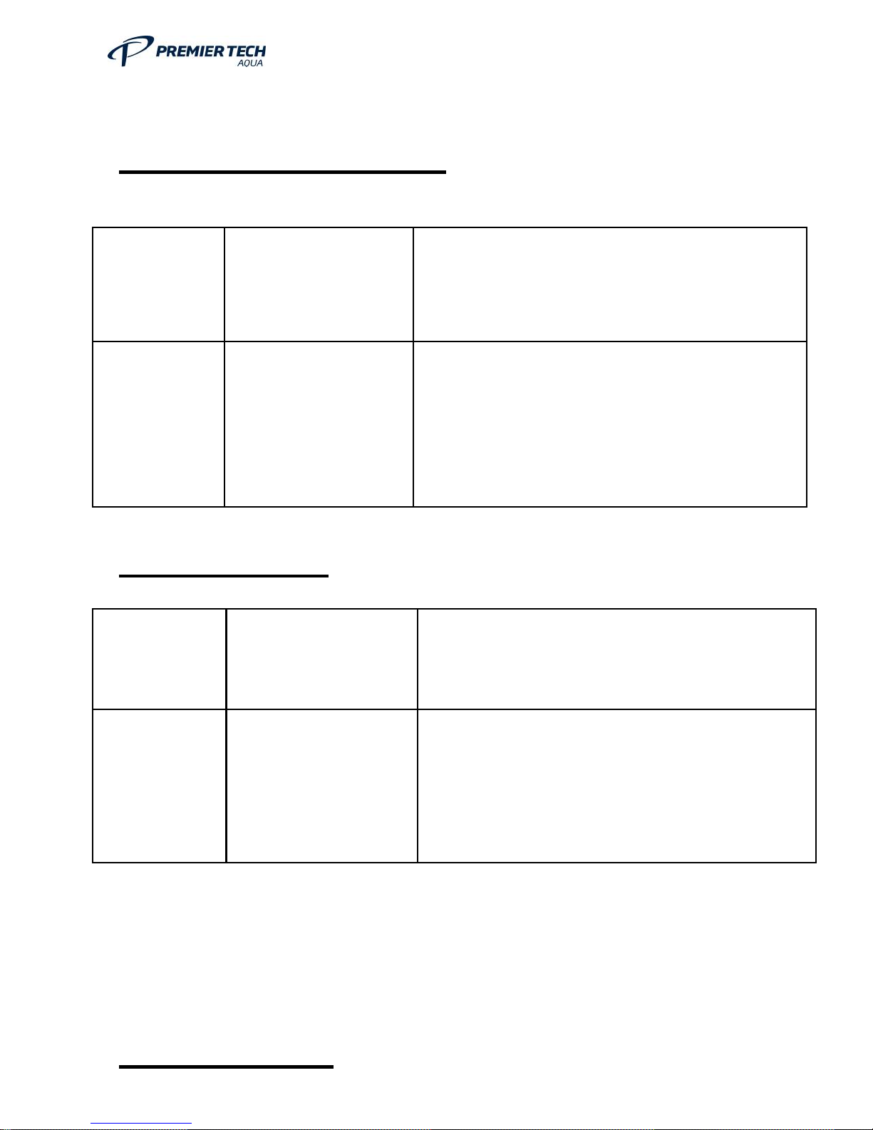
Maintenance records
Plant Commissioning
Date
Commissioning
Company
Notes
1st Plant Service
Date
Co
2nd Plant Service
Page 69
OM0006 Conder ASP HDPE Rev 5.2
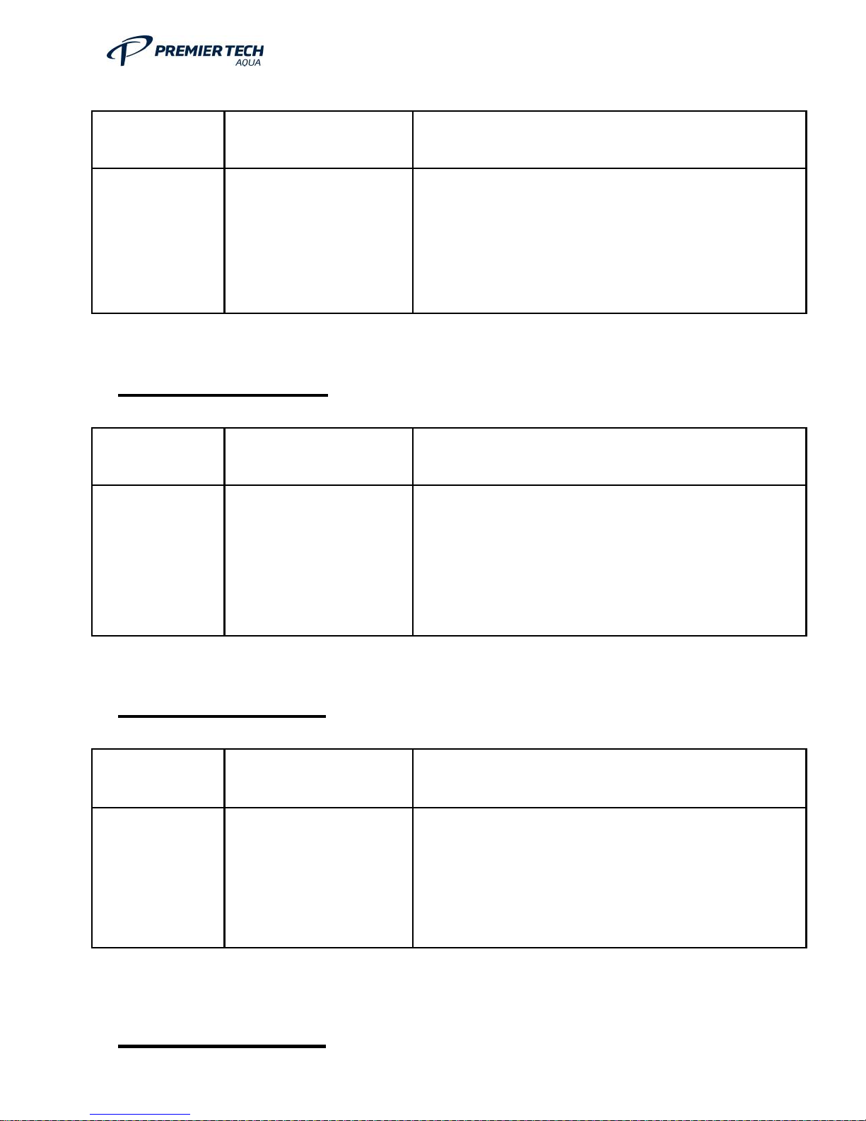
69
Date
Servicing Company
Notes
3rd Plant Service
Date
Servicing Company
Notes
4th Plant Service
Date
Servicing Company
Notes
5th Plant Service
Page 70
OM0006 Conder ASP HDPE Rev 5.2
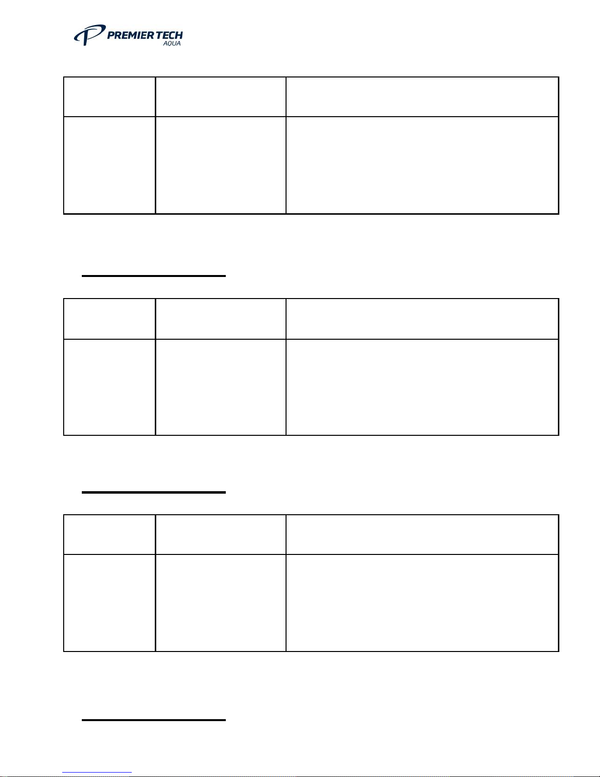
70
Date
Servicing Company
Notes
6th Plant Service
Date
Servicing Company
Notes
7th Plant Service
Date
Servicing Company
Notes
8th Plant Service
Page 71
OM0006 Conder ASP HDPE Rev 5.2
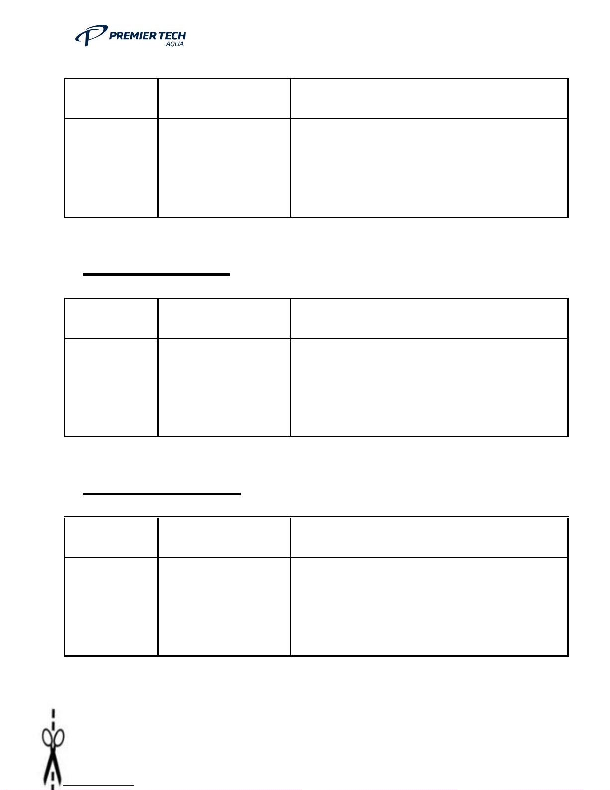
71
Date
Servicing Company
Notes
9th Plant Service
Date
Servicing Company
Notes
10th Plant Service
Date
Servicing Company
Notes
Page 72

OM0006 Conder ASP HDPE Rev 5.2
72
Thank you for
choosing Premier Tech Aqua. Your product must be registered to activate the standard warranty and any extended warranty offer
ed on certain product
ranges.
Products installed to protect the environment and avoid EA prosecution must be maintained and service
d regularly to ensure that they operate efficiently and effectively.
Premier Tech Aqua has a nationwide network of service partners that can offer complete service and maintenance packages for p
eace of mind.
Our service partners can also commission your
products should you wish.
In order to activate your extended warranty and a free post installation check, please use one of the following options:
Option 1:
Log onto
www.premiertechaqua.co.uk
and complete th
e online Product Warranty Activation Form
Option 2:
Complete and return this form to us:
Name ____________________________________
_________________________________________
Address _____________________________________
________________________________________
Postcode __
___________________________________________________________________________
Telephone Number _____________________________________________
________________________________
Email Address
_____________________________________________________________________________
Site Address (if different) __________________________________
___________________________________________
Product Purchased ____________________________________________
_________________________________
Reference Number (if known)
_____________________________________________________________________________
Where Purchased ____________________________________________
_______________________________
__
Proof of Purchase __________________________________________
___________________________________
Please contact me regarding: Commissioning quo
tations Service and maintenance quotations
PRODUCT WARRANTY ACTIVATION FORM
2 Whitehouse Way, South West Industrial Estate, Peterlee, Co. Durham, SR8 2RA, UNITED KINGDOM
Page 73
OM0006 Conder ASP HDPE Rev 5.2
73
Prem ier Tech Aqua,
2 Whi tehouse Way,
Sou th West Indus trial Estate,
Pete rlee,
Co. Du rham,
SR8 2 RA
Premier Tech Aqua Ltd 2 Whitehouse Way,
South West Industrial Estate, Peterlee, Co. Durham, SR8 2RA
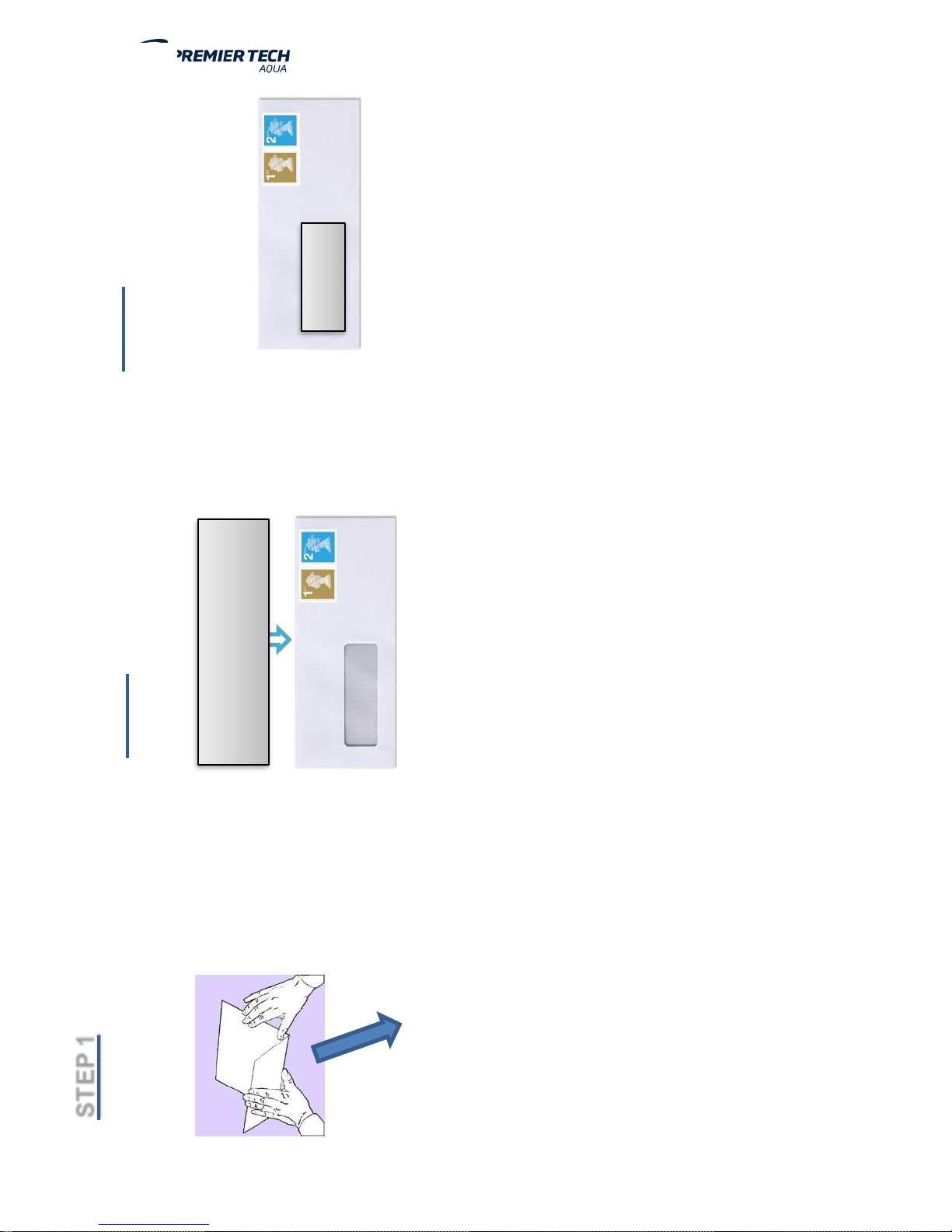
STEP 2
Fit Warranty Activation Form inside
Envelope (see reverse for details)
STEP 1
Fold on Line
STEP 3
Apply correct amount of Stamps
Premier Tech Aqua, 2 Whitehouse Way, South West Industrial Estate,
Peterlee,
Co. Durham,
SR8 2RA
 Loading...