

PremierOne MUV-403H Installation & Maintenance Instructions Manual
MUV-403H MultiVoltage
Oxidizing UVC System
Installation & Maintenance Instructions
UNPACKING THE UNIT
Each unit is shipped with the 5” lamp installed and the germicidal lamp
placed in a box with protective packaging. Carefully remove lamp from
the tube taking care to not touch the glass portion of the lamp with bare
hands. Oils from the hands can cause “hot spots” which reduce lamp life.
Handle by the end caps or use a soft cloth. If you accidentally touch
a lamp, clean it using the included alcohol cleaning pad or a soft cloth
dampened with rubbing alcohol. The lamp is fragile and proper care
must be taken when removing from packaging.
The following parts are included: • MUV-403H Unit
• Germicidal Twin H Lamp (packed in lamp box)
• Four Sheet Metal Screws
• Installation & maintenance instructions
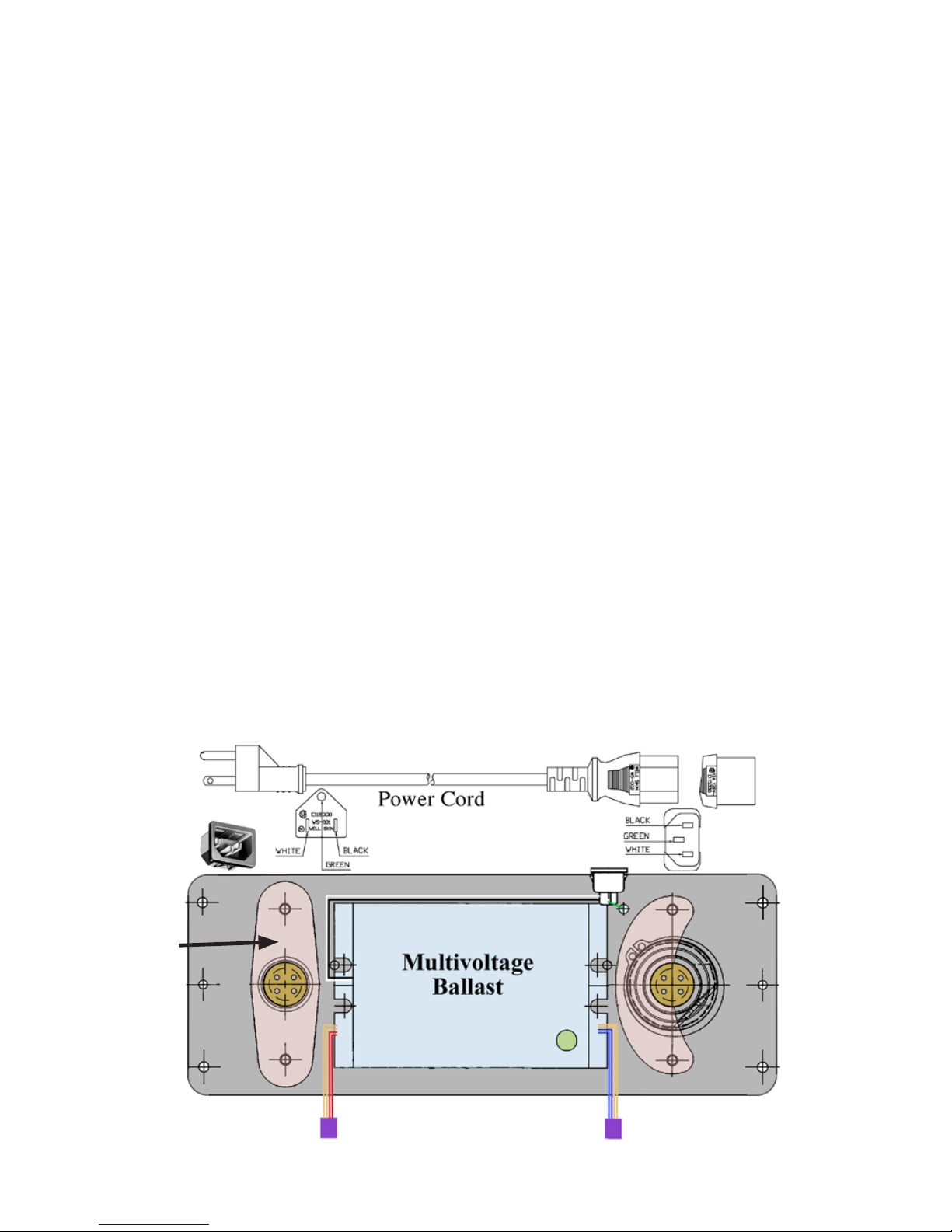
• 120 VAC Power Cord (PC-120)
• Alcohol pad for cleaning lamps
When installing and using this electrical equipment, basic safety precautions
should always be followed including the following:
1. READ AND FOLLOW ALL INSTRUCTIONS.
2. Minimum living space for this product is 1,200 square feet.
3. Always be sure the unit is unplugged during installation or service procedures.
4. The ultraviolet light produced by the UV lamp is harmful to your eyes. Do not look directly at
the lamp. Should it become necessary to view the lamp, use UV-protected sunglasses.
Lors de l’installation et de l’utilisation de cet équipement, des précautions devront être suivies.
1- Lire et suivre les étapes attentivement.
2- Espace minimum d’une habitation pour ce produit est de 1,200 pi. carrés
3- Assurez vous de toujours débrancher avant l installation ou le service.
4- Ne pas regarder la lampe directement avec les yeux. Si nécessaire de le faire,
veuillez porter les lunettes de soleil contre les rayons U.V.
IMPORTANT: SAFETY INSTRUCTIONS
Important: Instructions de securité
3099107
INSTALLATION: Living space, 1,200 square feet minimum.
Best results are achieved when the unit is installed where the HVAC system air temperature is most constant.
Therefore, the preferred installation is on the return side of the furnace. If return side installation is not possible,
install the unit on the supply side. Mount the MUV-403H upstream when installing in combination with a polarized
media air cleaner.
If there is a device that creates ozone in the space such as an ionizing air cleaner, it is recommended the MUV-403H
not be used in the application. For example, an MUV-401H could be substituted. Homes with multiple air handlers:
install one MUV-403H on the main level air handler and an MUV-401H or MUV7-50PS on the other air handler(s).
Do not locate the unit within 20” of plastic materials that will be directly exposed to the UV light, such as wiring,
return side humidier or certain types of air lters. Check with the lter manufacturer to see if their material is UV
resistant. Over time, UV light may degrade some plastics and petroleum based materials.
Do not touch the glass portion of the lamps with bare hands because oils from the hands can cause “hot spots”
which reduce lamp life. Handle either by the end caps or use a soft cloth. If you accidentally touch a lamp, wipe it
off using the included alcohol cleaning pad or a soft cloth dampened with rubbing alcohol.
1. Cut out the shaded area of the installation template. (Please see insert.)
2. Center the template on the longitudinal axis of the plenum and attach with tape.
Trace the hole pattern for the unit and mark centers for mounting screws. (Airow direction is marked on the unit.)
3. Cut openings for the unit using a 2” hole saw or tin snips.
4. Remove the cover from the unit by removing the top and bottom retaining nuts using an 11/32 size
nut driver and set aside. Do not remove the oxidation control knob.
(For easier installation rotate control knob to the center position before removing cover.)
5. Attach the unit to the air duct using the four self tapping sheet metal screws provided.
6. Remove the germicidal lamp holder using a 11/32 size nut driver (Figure A).
7. Slide the germicidal lamp into lamp opening.
8. Reinstall the lamp holder and plug lamp into connector.
10. Replace cover and align the oxidizing control knob with adjustment linkage by gently turning the knob until the
linkage clicks into place. Secure cover using the two retaining nuts.
Figure A
Germicidal
lamp holder
16”lamp connector
5”lamp connector
 Loading...