

Premier Mounts XUT-3763 User Manual
INSTALLATION GUIDE: XUT-3763
Victory Tilt Screen Wall Mounting System
The Victory Tilt Screen Wall Mounting System is designed for secure installation of flat screen displays up
to 63”.
Warning Statements
THE WALL STRUCTURE MUST BE CAPABLE OF SUPPORTING AT LEAST A
MINIMUM WEIGHT OF 350 LBS. IF NOT, THE WALL MUST BE REINFORCED.
PROPER INSTALLATION PROCEDURE BY A QUALIFIED SERVIC E TECHNICIAN,
AS OUTLINED IN THE INSTALLATION INSTRUCTIONS, MU ST BE ADHERED T O.
FAILURE TO DO SO COULD RESULT IN SERIOUS PERSONAL IN JURY, OR EVEN
DEATH. DO NOT PLACE A UNIT WEIGHING MORE THAN 175LBS. ON THIS
MOUNT.
SAFETY MEASURES MUST BE PRACTICED AT ALL TIMES DURING THE
INSTALLATION OF THIS PRODUCT. USE PROPER SAF ETY GEAR AND TOOLS
FOR THE INSTALLATION PROCEDURE TO PREVENT PERSONAL INJURY.
PRIOR TO THE INSTALLATION OF THIS PRODUCT, THE INSTALLATION
INSTRUCTIONS SHOULD BE READ AND COMPLETELY UNDERSTOOD. THE
INSTALLATION INSTRUCTIONS MUST BE READ TO PREVENT PERSONAL
INJURY AND PROPERTY DAMAGE. KEEP THESE INSTALLATION
INSTRUCTIONS IN AN EASILY ACCESSIBLE LOCATION FOR FUTURE
REFERENCE.
A secure structure must support the weight, or load, of the display. When mounting to a
wall that contains wooden studs, dead center of the wooden stud must be confirmed prior to
installation.
Do not install on a structure that is prone to vibration, movement or chance of impact.
Failure to do so could result in damage to the display and/or damage to the mounting
surface.
Do not install near heater, fireplace, direct sunlight, air conditioning or any other source of
direct heat energy. Failure to do so may result in damage to the display and could increase
the risk of fire.
At least two qualified people should perform the installation procedure. Injury and/or
damage can result from dropping or mishandling the display.
Recommended mounting surfaces: wooden studs and solid-flat concrete. If the mount is to
be installed on any surface other than wooden studs, use suitable hardware (which is
commercially available).
Contact Victory Mounts with any technical/installation questions.
Included Hardware
Universal Washer
(Qty 8)
Flat Washers (Qty 6)
1/4" Nylon spacers
(large)
(Qty 6)
1/2" Nylon spacers
(large)
(Qty 12)
5/16" Flat washers
(metal)
(Qty 6)
1/4" Nylon spacers
(small)
(Qty 6)
Tool List
Phillips Head Screw Driver
Electronic Stud Finder
½” Socket and Wrench
Portable Drill
Masonry Bit for Concrete Installation
1/4” Drill Bit for Wood Installations
Level (Commercially Available)
Wood Stud Mounting
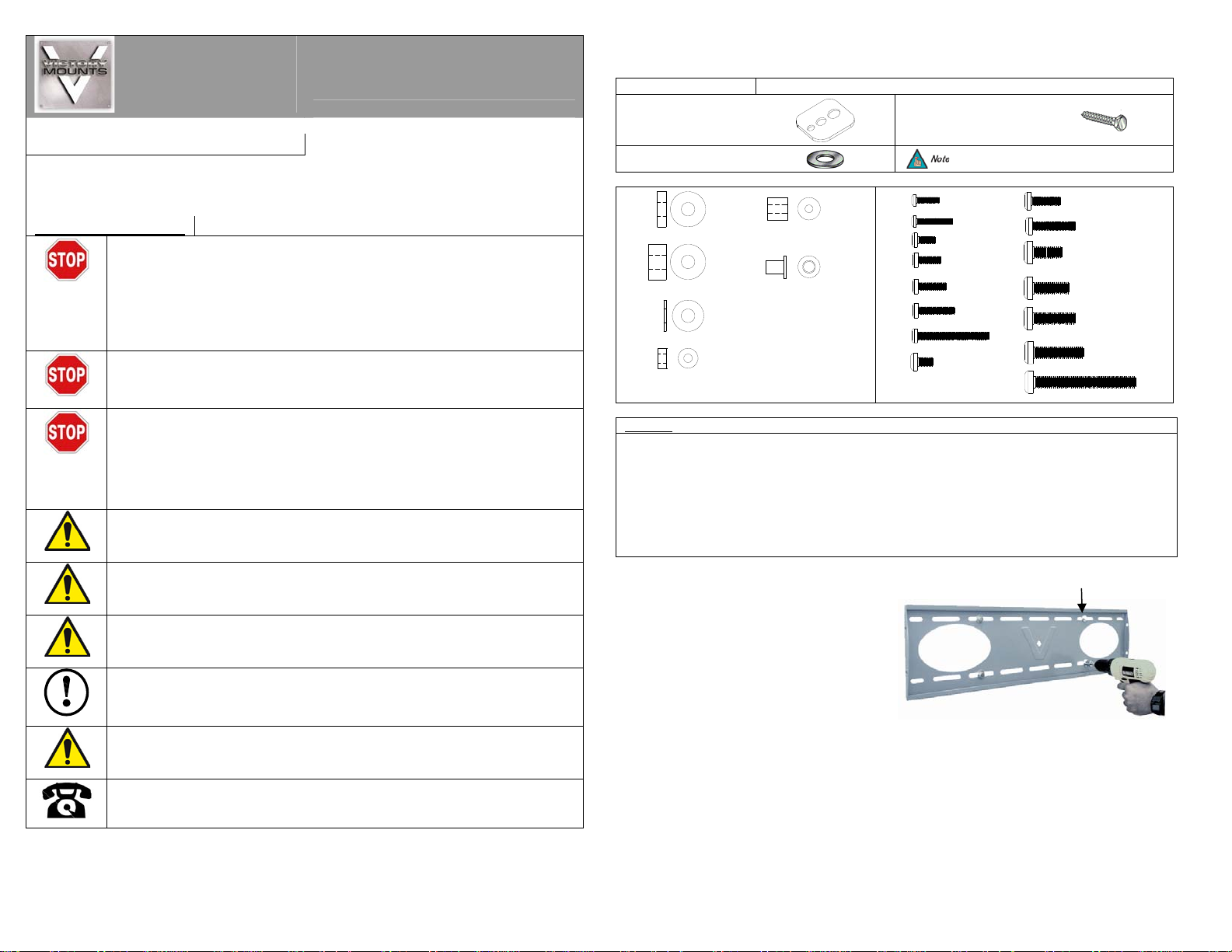
1. For secure wood stud mounting, the wall plat e must be
mounted to two studs at least 16” apart.
2. Use a high-quality electronic stud finder (commercially
available) to locate two adjacent studs and mark their
locations with a pencil.
3. With the help of an assistant, use a level (commercially
available) and position the wall plate agains t the wal l in
the desired mounting location.
4. Mark the right, upper and lower and the left (upper
and lower), positions of the small horizontal slots
that are in alignment with the studs.
5. You should mark four positions total.
6. Next, pre-drill a 1/4” hole in the wall stud at each
marked location.
9/16" Nylon spacers
(Qty 6)
Nylon sleeves
(Qty 4)
3” Lag Bolts
(Qty 6)
M4 x 16
M4 x 25
M5 x 12
M5 x 16
M5 x 20
M5 x 25
M5 x 50
M6 x 12
To correctly determine your hardware, please
refer to the hardware list below.
(Qty 8)
(Qty 8)
(Qty 8)
(Qty 6)
(Qty 6)
(Qty 4)
(Qty 4)
M6 x 20
M6 x 30
M8 x 20
M8 x 25
M8 x 30
(Qty 4)
M8 x 35
M8 x 70
(Qty 6)
(Qty 6)
(Qty 6)
(Qty 6)
(Qty 6)
(Qty 4)
Lag Bolt and Washer
Continued on back page
(Qty 4)
9531-015-122-06
Continued from front page
7. With the help of an assistant, position the wall plate against the wall and line up the mounting slots with
drilled holes.
8. For each location, insert a lag bolt and washer into the wall.
9. Tighten each bolt with an open ended socket wrench by turning clockwise until tight.
Do NOT over-tighten lag bolts when attaching the mount to the wall. Improper installation may
result in personal injury or damage to property.
Concrete Mounting
1. Begin by placing the wall plate into position against the wall, using the bubble guide to
keep it level.
2. Mark off six holes to be used for securing the mount and place the wall plate aside.
3. Next, drill holes using an electric drill and masonry bit.
4. Insert a concrete anchor into each hole.
5. If necessary, a hammer can be used to lightly tap each anchor into place so that they are flush with the
wall.
6. Once all of the anchors are in place, move the wall plate back into position.
7. Attach the nut onto the threaded shaft that is protruding from the wall.
8. Do not tighten until all nuts are in place.
Do not release the wall plate until it is properly mounted and secured to the wall.
The concrete anchors must be used for concrete installation. They can be purchased at your local
hardware store.
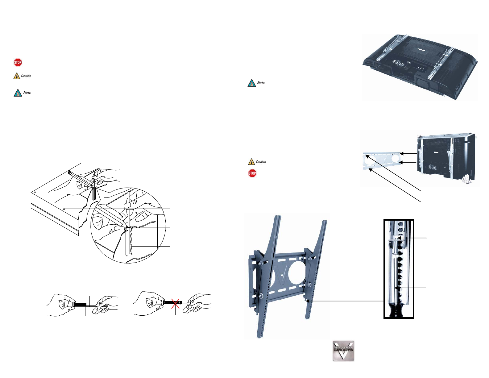
How to Determine Thread Depth
Inverted Flat
Panel Display
Marking the
Depth
Thread Insert
Thread Depth
Indicator
Figure 1
Screw
Screw
Figure 2
Marking
Stir Straw
or
Toothpick
Marking
Stir Straw
or
Toothpick
Figure 3
Display Bracket Installation
1. To ensure optimal installation, this kit includes various
screws of different diameters and lengths.
2. Place your flat panel screen down on a soft, flat surface,
and locate the threaded mounting points that are located
on the back of the display.
3. Determine which screw is the correct length by carefully
inserting a straw, o r toothpick, and mark how deep the
mounting point is.
4. If your display has a curved back or a recessed thread
mounting point, a spacer must be used.
5. Place the spacer between the mounting bracket and
the display.
6. If a smaller screw is being used (M4, M5, or M6)
please use a square griplate with each screw for
added stability.
7. Attach each bracket to the display by aligning the
holes on each bracket, with the threaded inserts on
the back panel of your display, inserting the screws
through both and turning clockwise until they are fully
inserted.
8. Tighten with a Phillips head screw driver.
Final Installation
1. To complete the installation of your new plasma
mount, carefully place the flat panel brackets over the
upper and lower mounting lips.
2. Use a Phillips head screwdriver to tighten the two (2)
security bracket screws (see inset below).
Select the spacer that is closest in depth to the
recess to keep your bracket as close to the display
as possible.
Two people are required for this step.
MAKE SURE THE LOCKING SCREW IS FLUSH
WITH THE LOCKING SCREW TAB BEFORE
INSTALLATION.
Upper Mounting Lip
Lower Mounting Lip
Progressive Marketing Products, Inc.
3130 E. Miraloma Ave.
Anaheim, CA 92806
800-368-9700
victory@mounts.com
Locking Screw
Screwdriver
 Loading...