

Premier Mounts WMK-027 User Manual
ViewSonic by Premier Mounts
INSTALLATION INSTRUCTIONS
WMK-027
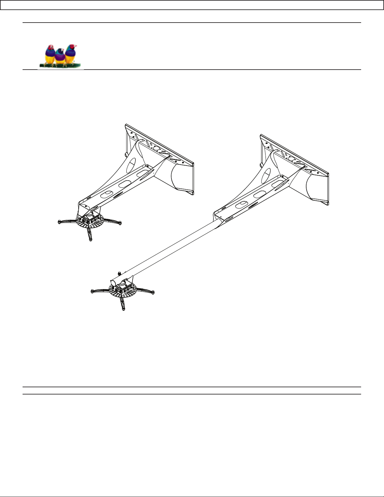
Universal Short Throw Wall Mount
NORTH AMERICA
3130 East Miraloma Avenue
Anaheim, CA 92806 USA
USA and Canada –
Phone: 800-368-9700
Fax: 800-832-4888
Other Locations – Phone: (001)-714-632-7100; Fax: (001)-714-632-1044
©Premier Mounts 2009
9530-070-353-00
EUROPE
Swallow House,
Shilton Industrial Estate,
Shilton, Coventry, England CV79JY
Phone: +44 (0) 2476 614700
Fax: +44 (0) 2476 614710

WMK-027
Table of Contents
Warning Statements 2
Parts List 3
Installation Tools 3
Determining the Installation Height 4
Wood Stud Installation 5
Solid Surface Installation 6
Utilizing the Storage Feature 7
Attaching the Projector Arm 7
Throw Distance Calculation 8
Upper Mounting Bracket Installation 9
Extension Arm Installation 10
Base Box Installation 10
Cable Management 11
Set Screw Installation (Optional) 11
Technical Specications 12
Warranty 13
Warning Statements
PRIOR TO THE INSTALLATION OF THIS PRODUCT, THE INSTALLATION INSTRUCTIONS SHOULD BE READ AND COMPLETELY UNDERSTOOD. THE INSTALLATION INSTRUCTIONS MUST BE READ TO PREVENT PERSONAL INJURY AND
PROPERTY DAMAGE. KEEP THESE INSTALLATION INSTRUCTIONS IN AN EASILY ACCESSIBLE LOCATION FOR FUTURE
REFERENCE.
PREMIER MOUNTS DOES NOT WARRANT AGAINST DAMAGE CAUSED BY THE USE OF ANY PREMIER MOUNTS PRODUCT
FOR PURPOSES OTHER THAN THOSE FOR WHICH IT WAS DESIGNED OR DAMAGE CAUSED BY UNAUTHORIZED ATTACHMENTS OR MODIFICATIONS, AND IS NOT RESPONSIBLE FOR ANY DAMAGES, CLAIMS, DEMANDS, SUITS, ACTIONS OR
CAUSES OF ACTION OF WHATEVER KIND RESULTING FROM, ARISING OUT OF OR IN ANY MANNER RELATING TO ANY
SUCH USE, ATTACHMENTS OR MODIFICATIONS.
THE SURFACE MUST BE CAPABLE OF SUPPORTING AT LEAST FIVE TIMES THE WEIGHT OF THE PROJECTOR. IF NOT,
THE STRUCTURE MUST BE REINFORCED. THE MAXIMUM WEIGHT THAT CAN BE USED WITH THIS PRODUCT IS 75LBS.
PROPER INSTALLATION PROCEDURE BY A QUALIFIED SERVICE TECHNICIAN, AS OUTLINED IN THE INSTALLATION
INSTRUCTIONS, MUST BE ADHERED TO. FAILURE TO DO SO COULD RESULT IN SERIOUS PERSONAL INJURY, OR EVEN
DEATH.
SAFETY MEASURES MUST BE PRACTICED AT ALL TIMES DURING THE ASSEMBLY OF THIS PRODUCT. USE PROPER
SAFETY GEAR AND TOOLS FOR THE ASSEMBLY PROCEDURE TO PREVENT PERSONAL INJURY.
At least two qualied people should perform the assembly procedure. Injury and/or damage can result from dropping or mishandling the
projector.
If mounting to studs, make sure that the mounting screws are anchored into the center of the studs. Use of an edge-to-edge stud nder is
recommended.
Be aware of the mounting environment. If drilling and/or cutting into the mounting surface, always make sure that there are no electrical wires
in wall. Cutting/drilling into an electrical line may cause serious injury.
Make sure there are no water lines inside the wall where the mount is to be located. Cutting/drilling into a water line may cause severe water
damage to the mounting surface.
This product is intended for indoor use only. Use of this product outdoors could lead to product failure and personal injury.
Do not install near sources of high heat. Do not install on a structure that is prone to vibration, movement or chance of impact
Contact Premier Mounts with any questions
(800) 368-9700
techsupport@mounts.com
Page 2 Installation Instructions
WMK-027
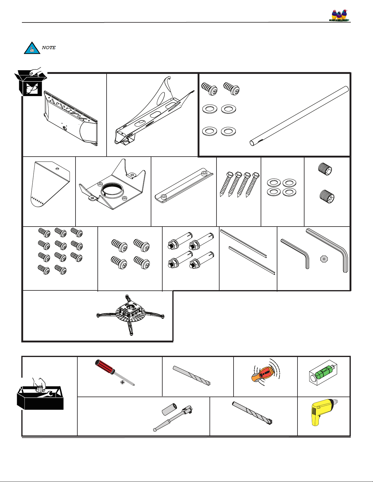
Parts List
This mount is shipped with all proper installation hardware and components. Make sure that none of these parts are
missing and/or damaged before beginning installation. If there are parts missing and/or damaged, please stop the
installation and contact Premier Mounts (800) 368-9700.
Extension Hardware Pack
M6 x 12mm Security (Qty 2)
1/4” Flat Washer (Qty 2)
Wall Plate (Qty 1)
End Cover (Qty 1)
Upper Mounting Bracket
M5 x 12mm Security Head
Screws (Qty 11)
PDS-PLUS Projector
Mount
Arm Assembly (Qty 1)
(Qty 1)
M6 x 12mm Security
Head Screws (Qty 4)
1/4” Nylon Spacer
(Qty 2)
Inner Slide Plate (Qty 1)
3/8” Concrete Wedge
Anchors (Qty 4)
5/16 x 3” Lag
Bolts (Qty 4)
Back Plate
Covers (Qty 2)
Extension Arm - Optional (Qty 1)
included with the WMK-027
Non-Security (Qty 1)
5/16 Flat
Security (Qty 1)
M6 Set Screws
Washers (Qty 4)
M5
M3
Security Wrenches
(PDS-PLUS Hardware Pack)
Installation Tools (not supplied)
Phillips Screwdriver
1/2” Socket and Socket
Wrench
1/4” Drill Bit
Electronic Stud Finder
3/8” Masonry Drill Bit
Installation Instructions Page 3
Level
Drill
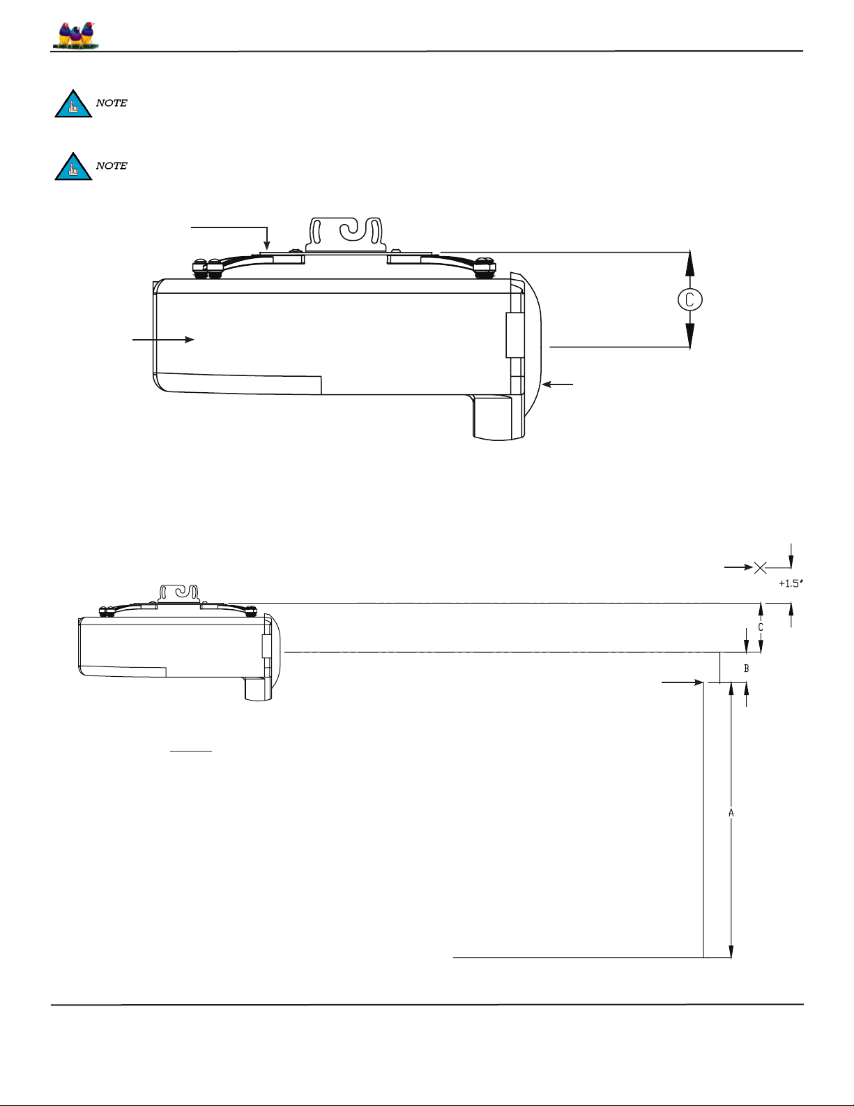
Determining the Installation Height
In order to determine the installation height and throw distance, the PDS-PLUS projector bracket must be mounted to the
projector. Please refer to the PDS-PLUS Installation Instructions prior to performing the following steps.
Refer to the projectors User’s Manual to determine the offset of the projector lens to the top of the screen/whiteboard.
PDS-PLUS Bracket
Projector
WMK-027
Lens
Step 1. Measure distance from center of lens to the top of the PDS-PLUS bracket.
Step 2. Add the distance from the ground to the top of the screen (A), the recommended offset from the projector manual (B),
the measurement from Step 1 (C), and then add 1.5”.
(Example: A + B + C + 1.5” = ?)
Step 3. Measure the calculated distance from the top edge of the viewable area of the screen/whiteboard and mark the wall. This mark
will represent the lower edge of the wall plate.
Mark
Top of Screen
Legend
A - Distance from ground to the top of the
screen/whiteboard (viewable area).
B - Manufacturers recommended offset
measurement. This measurement will be
listed in the Users Manual.
C - Center of the lens to the top of the
PDS-PLUS bracket.
Add 1.5” to the calculated total. This total distance
will be the location for the bottom rail on the wall
Ground
plate.
Page 4 Installation Instructions
 Loading...