

Page 1
INSTALLATION INSTRUCTIONS
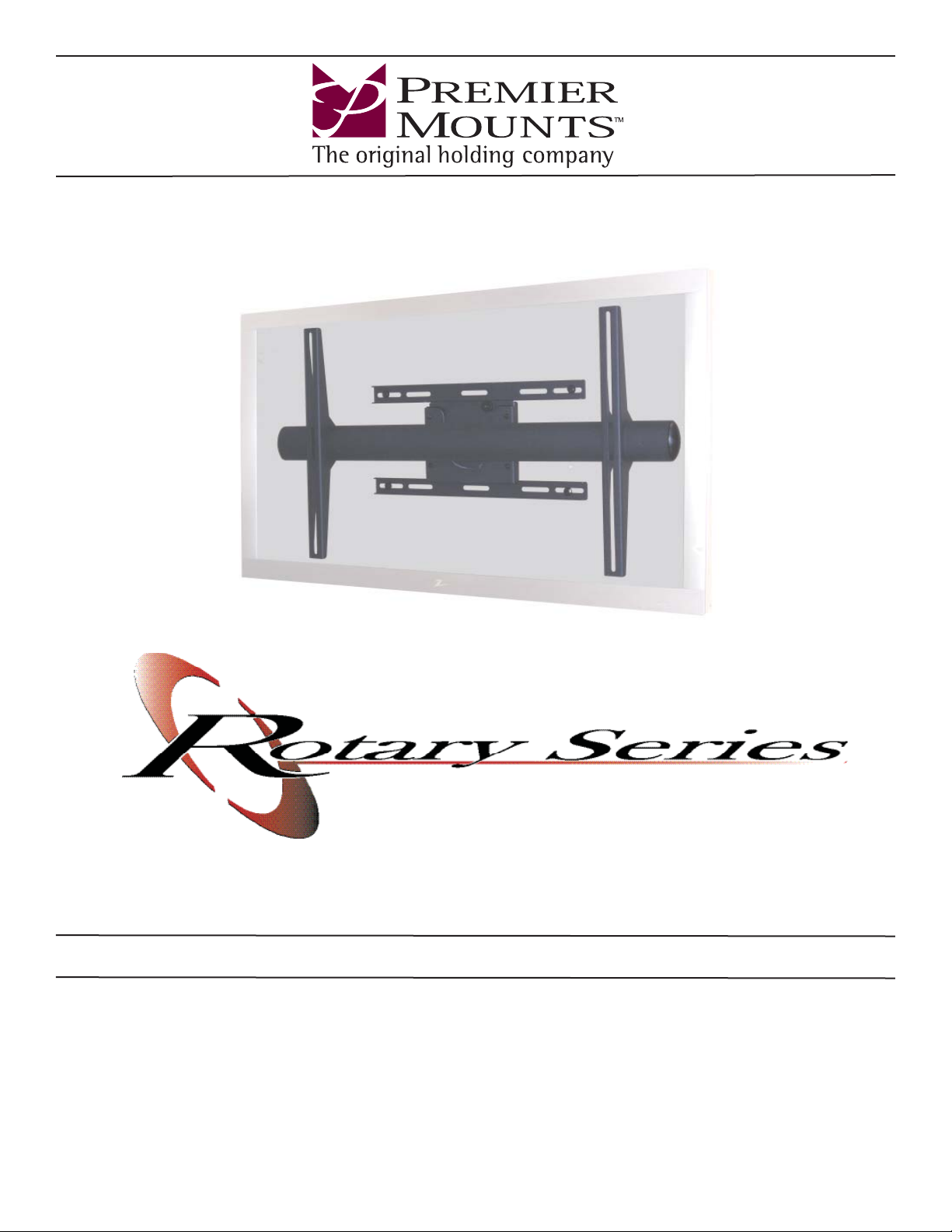
Rotary Flat Mount
Model: RFM
NORTH AMERICA
3130 East Miraloma Avenue
Anaheim, CA 92806 USA
USA and Canada –
Phone: 800-368-9700
Fax: 800-832-4888
Other Locations – Phone: (001)-714-632-7100; Fax: (001)-714-632-1044
©Premier Mounts 2008
9531-009-041-03
Shilton Industrial Estate,
Shilton, Coventry, England CV79JY
Phone: +44 (0) 2476 614700
Fax: +44 (0) 2476 614710
EUROPE
Swallow House,
AUSTRALIA, NEW ZEALAND, OCEANIA
(DISTRIBUTOR)
P.O. Box 295
Mordialloc Victoria 3195
Australia
Phone: 039586 6330
www.premiermounts.com.au
Page 2
Table of Contents
Contact Premier Mounts 2
Warning Statements 3
Parts List 4
Installation Tools 4
Thread Depth Indicator 7
Mount Installation 8
Concrete Mounting 9
Universal Mounting Bracket Installation 9
Display Orientation 11
Technical Specifications 11
Warranty 12
Warning Statements
PRIOR TO THE INSTALLATION OF THIS PRODUCT, THE INSTALLATION INSTRUCTIONS SHOULD BE READ AND
COMPLETELY UNDERSTOOD. THE INSTALLATION INSTRUCTIONS MUST BE READ TO PREVENT PERSONAL
INJURY AND PROPERTY DAMAGE. KEEP THESE INSTALLATION INSTRUCTIONS IN AN EASILY ACCESSIBLE
LOCATION FOR FUTURE REFERENCE.
PREMIER MOUNTS DOES NOT WARRANT AGAINST DAMAGE CAUSED BY THE USE OF ANY PREMIER MOUNTS
PRODUCT FOR PURPOSES OTHER THAN THOSE FOR WHICH IT WAS DESIGNED OR DAMAGE CAUSED BY
UNAUTHORIZED ATTACHMENTS OR MODIFICATIONS, AND IS NOT RESPONSIBLE FOR ANY DAMAGES, CLAIMS,
DEMANDS, SUITS, ACTIONS OR CAUSES OF ACTION OF WHATEVER KIND RESULTING FROM, ARISING OUT OF OR
IN ANY MANNER RELATING TO ANY SUCH USE, ATTACHMENTS OR MODIFICATIONS.
RFM
THE SURFACE MUST BE CAPABLE OF SUPPORTING AT LEAST FIVE TIMES THE WEIGHT OF THE DISPLAY. IF NOT,
THE SURFACE STRUCTURE MUST BE REINFORCED. THE MAXIMUM WEIGHT THAT CAN BE USED WITH THIS
PRODUCT IS 160LBS. PROPER INSTALLATION PROCEDURE BY A QUALIFIED SERVICE TECHNICIAN, AS OUTLINED
IN THE INSTALLATION INSTRUCTIONS, MUST BE ADHERED TO. FAILURE TO DO SO COULD RESULT IN SERIOUS
PERSONAL INJURY, OR EVEN DEATH.
SAFETY MEASURES MUST BE PRACTICED AT ALL TIMES DURING THE ASSEMBLY OF THIS PRODUCT. USE
PROPER SAFETY GEAR AND TOOLS FOR THE ASSEMBLY PROCEDURE TO PREVENT PERSONAL INJURY.
At least two qualified people should perform the assembly procedure. Injury and/or damage can result from dropping or mishandling
the display.
If mounting to studs, make sure that the mounting screws are anchored into the center of the studs. Use of an edge-to-edge stud finder
is recommended.
Be aware of the mounting environment. If drilling and/or cutting into the mounting surface, always make sure that there are no electrical wires in wall. Cutting/drilling into an electrical line may cause serious injury.
Make sure there are no water lines inside the wall where the mount is to be located. Cutting/drilling into a water line may cause
severe water damage to the mounting surface.
This product is intended for indoor use only. Use of this product outdoors could lead to product failure and personal injury.
Do not install near sources of high heat. Do not install on a structure that is prone to vibration, movement or chance of impact
Contact Premier Mounts with any questions
(800) 368-9700
[email protected]
Page 2 Installation Instructions
Page 3
RFM
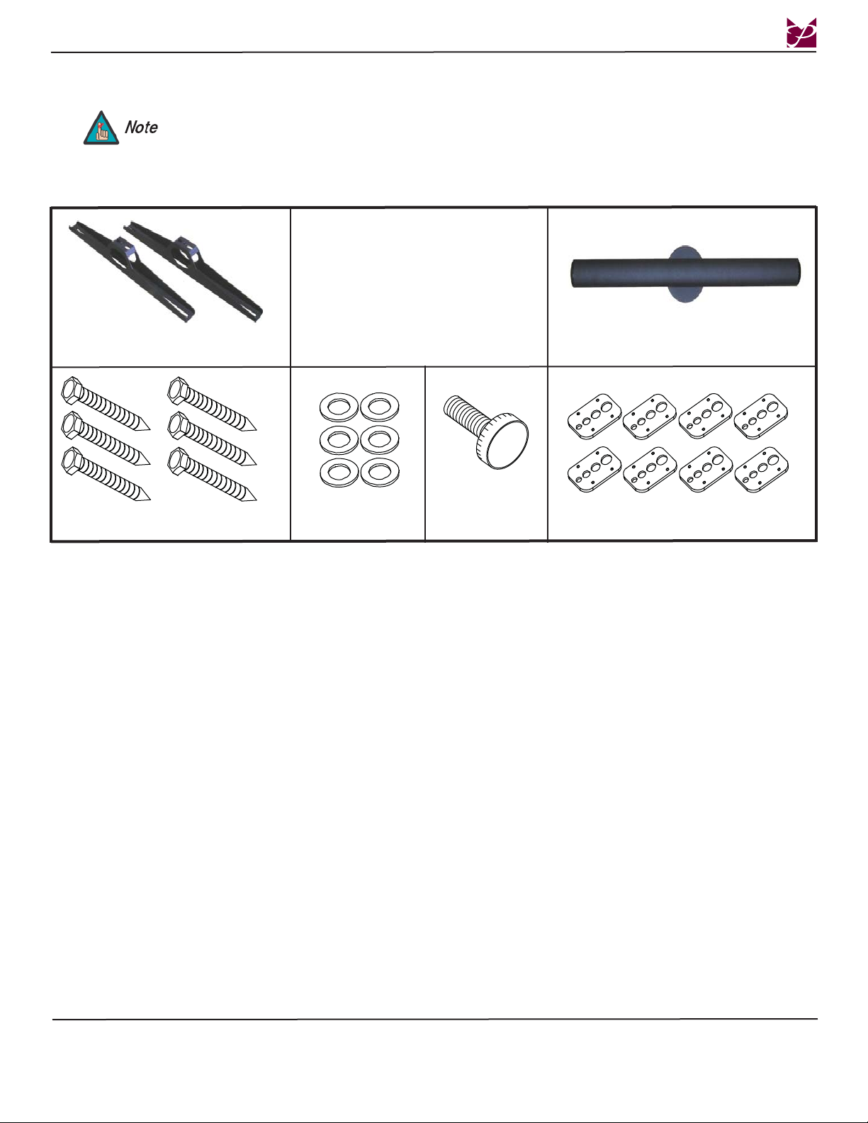
Parts List
Universal Mounting Brackets (Qty 2)
5/16” x 3” Lag Bolts - wooden studs
This mount is shipped with all installation hardware and components. Make sure that none of these parts are
missing and/or damaged before beginning installation. If there are parts missing and/or damaged, please stop and
contact Premier Mounts (800) 368-9700.
only (Qty 6)
5/16” Flat Washers
(Qty 6)
M6 Knurl Knob
(Qty 1)
Rotating Universal Bracket Bar (Qty 1)
Griplate™ (Qty 8)
Installation Tools
Phillips Head Screw Driver Soft Material/Blanket 1/2” Socket and Wrench
Pencil Tape Measure Drill Gun
Level (Supplied) M5 Allen Wrench (Supplied) 5/32” Allen Wrench (Supplied)
1/4” Drill Bit (Pilot Holes) Thread Depth Indicator (Supplied)
Masonry Drill Bit (Concrete Applications - Commercially Available)
Installation Instructions Page 3
Page 4
RFM
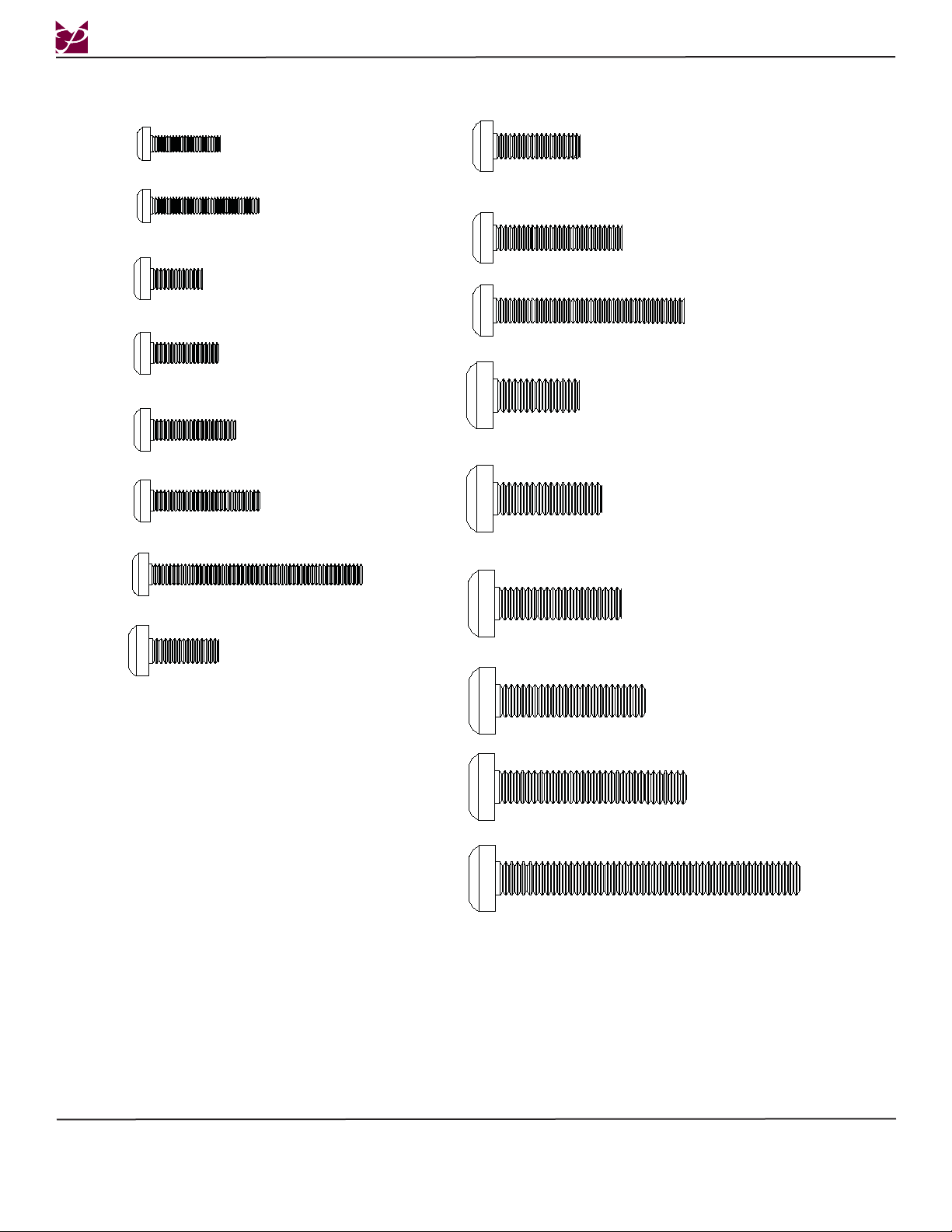
M4 x 16
M4 x 25
M5 x 12
M5 x 16
M5 x 20
M5 x 25
M5 x 50
(Qty 8)
(Qty 8)
(Qty 8)
(Qty 8)
(Qty 8)
(Qty 8)
M6 x 20
M6 x 30
M6 x 45
M8 x 20
M8 x 25
(Qty 8)
(Qty 8)
(Qty 8)
(Qty 8)
(Qty 8)
(Qty 8)
M6 x 16
(Qty 8)
M8 x 30
M8 x 35
M8 x 45
M8 x 70
(Qty 8)
(Qty 8)
(Qty 8)
(Qty 4)
Page 4 Installation Instructions
Page 5
RFM
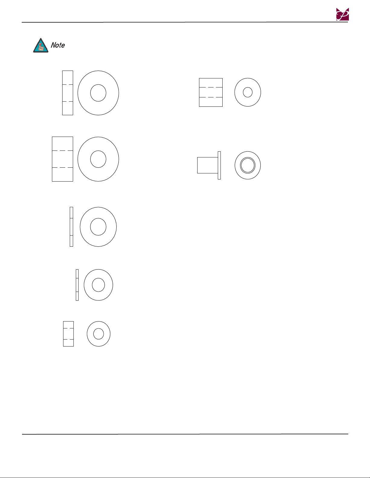
The nylon spacers may be stacked to achieve proper spacing.
1/4" Nylon spacer
(large
)
s
9/16" Nylon spacers
(Qty 8
)
(Qty 8)
1/2" Nylon spacers
(large
)
(Qty 12)
Nylon sleeves
(Qty 8)
5/16" Flat washers
(metal
)
(Qty 8)
1" Nylon Spacers
(Qty 8
)
1/4" Nylon spacer
(small
)
(Qty 8)
s
Installation Instructions Page 5
Page 6
RFM
Thread Depth Indicator
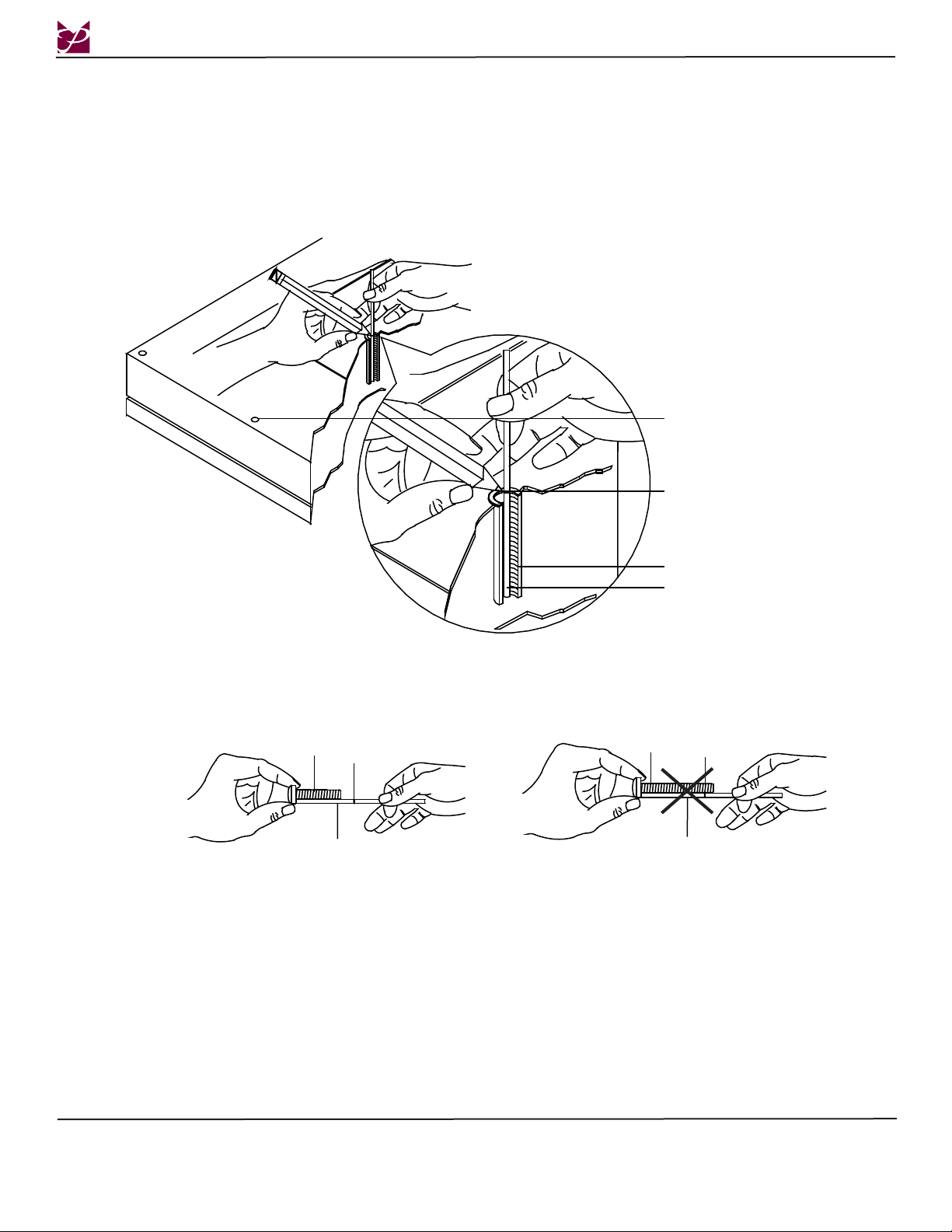
1. Insert the thread depth indicator (supplied) through the thread inserts found on the back of the fl at panel to make sure the inserts
measure the same full depth and mark it (Figure 1).
2. Locate the correct diameter screw for the thread insert. Compare your marking to the screws (supplied).
3. If your selected screw is longer than the marking on the thread depth indicator, DO NOT USE this screw.
4. The screw length must not bypass the marking. Select another screw size (Figure 2 and 3), until you fi nd one that comes closest to
your mark without going past.
Inverted Flat
Panel Display
Marking the
Depth
Screw
Thread Depth
Indicato
Marking
Thread Insert
Thread Depth
Indicato
Scre
w
Thread Depth
r
Indicator
r
Marking
Page 6 Installation Instructions
Page 7
RFM
Mount Installation
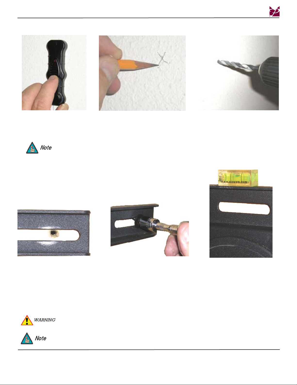
Step 1
Determine where the mount location will be. Use a stud finder
to locate the nearest wall stud.
For ease of installation, it is recommended that two people perform the installation. One person should hold the
mount while the other person installs the lag bolt and washer. Making sure that the mount is level, the person not
holding the mount must mark and drill the second mounting hole and secure the second lag bolt and washer.
Step 2 Step 3
Once the stud has been located, use a pencil
to mark the spot.
Using a 1/4” drill bit, drill the upper mounting hole where the mark was made.
Step 4
After the holes have been pre-drilled,
line up the mounting slot openings
with the pre-drilled holes.
Do NOT over-tighten lag bolts when attaching the mount to the wall. Improper installation may result in personal
injury or damage to property.
If the studs are 12” (304.8mm) apart, use three (3) 3” (76.2mm) lag bolts for the top rail and three (3) 3” (76.2mm)
lag bolts for the lower rail. If the studs are 16”(406.4mm), 18” (457.2mm) or 24” (609.6mm) apart, use two (2) 3”
lag bolts for the top rail and two (2) 3” lag bolts for the lower rail.
Step 5
Insert two (2) 5/16” x 3” lag bolts
and washers into the mounting holes
and tighten (see WARNING: below
Place a level (supplied) on the top
rail and make sure that the mount is
level. Once the mount is level, Drill
pilot holes in the lower mounting
slots and install two (2) 5/16” x 3”
lag bolts and washers into the mounting holes and tighten.
Step 6
Installation Instructions Page 7
Page 8
Concrete Mounting
RFM
1. Begin by placing the mount into position against the wall, keeping it level.
2. Mark off four holes to be used for securing the mount.
3. Next, drill holes using a masonry bit for your anchors (recommended masonry bit).
4. Insert a commercially available concrete anchor into each hole (recommended 3/8” wedge anchors).
5. If necessary, a hammer can be used to lightly tap each anchor into place so that they are flush with the wall.
6. Once all of the anchors are in place, move the wall bracket into position.
7. Attach the nut onto the threaded shaft that is protruding from the wall.
8. Do not tighten until all nuts are in place.
Concrete anchors must be used for concrete installation. They can be purchased at your local hardware store. The
mounting surface must be a minimum 6” thick.
Universal Mounting Bracket Assembly
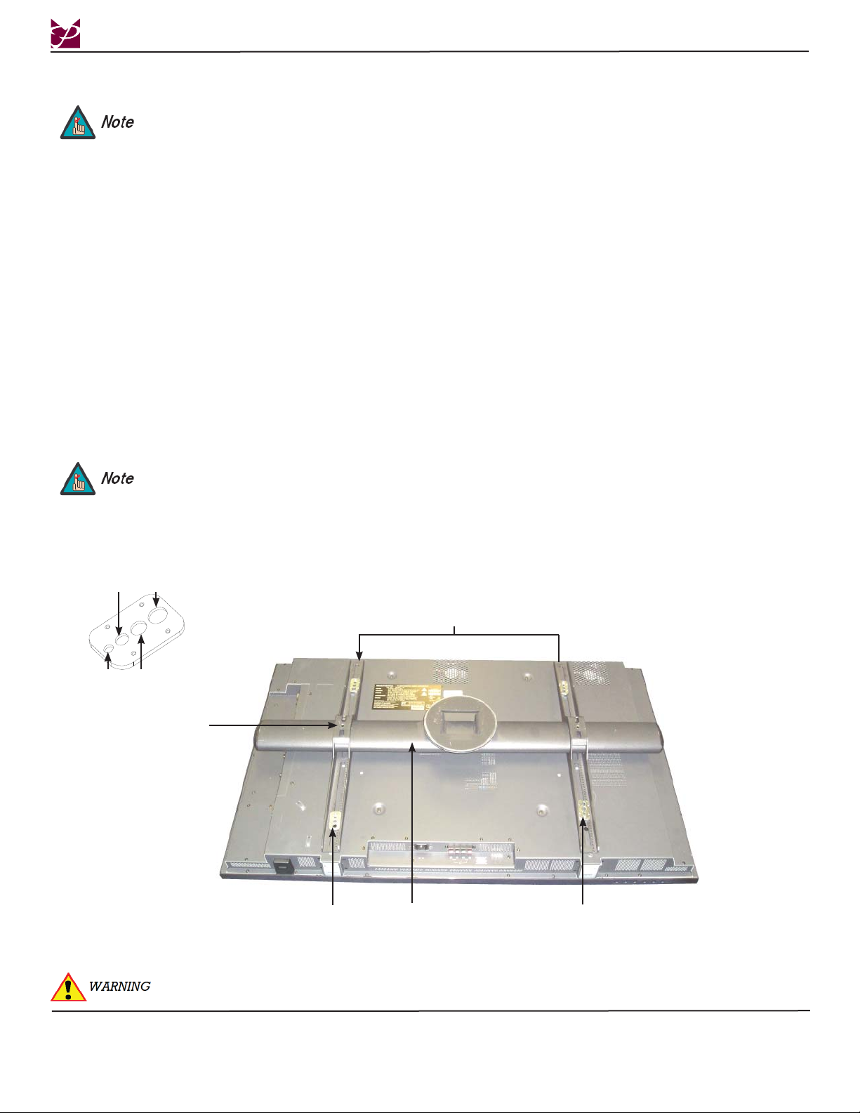
1. Place the universal bracket bar and the universal brackets on a flat surface.
2. Slide the universal brackets onto the universal bracket bar (as shown below) with the set screws facing up. At this
time, do not tighten the set screws that are located on the universal bracket.
3. Place the display on a soft, flat surface, face-down. Next, place the universal bracket assembly on the back of the
display, with the universal brackets resting directly over the display mounting points.
4. Once the desired position has been determined, place the Griplate™ washers over each mounting point and secure
them using the appropriate hardware (see Page 5).
5. At this time, center the universal bracket bar and tighten the set screws that are located on the universal brackets.
For the two upper mounting points, the Griplate™ flat side must be facing up. For the two lower mounting points, the
Griplate™ flat side must be facing down.
M5
M4
M8
Universal Mounting Brackets
M6
Set Screw
Griplate™
IT WILL TAKE TWO PEOPLE TO COMPLETE THE NEXT INSTALLATION STEP.
Universal Bracket Bar
Griplate™
Page 8 Installation Instructions
Page 9
RFM
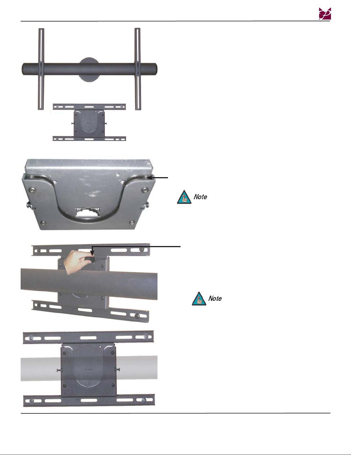
6. Lower the universal bracket bar with attached
display into the cradle (as shown to the left).
Nylon
Sleeve
After loosening the tension bolts, be sure that the
nose piece is held together tightly before rotating.
Knurl Knob Mounting Point/M6 x 12mm Security Head and
M6 Lock Washer Mounting Point.
7. Insert an M6 Knurl Knob/M6 x 12mm Security
Head and M6 Lock Washer into the knurl knob/
security screw mounting point and tighten.
To access the knurl knob/security screw
location while the display is attached, the
RFM must be rotated to the “portrait”
position (vertical position
8. Tighten the two (2) Phillips head screws (located
on the side of the mounting block) once the final
position is attained.
Installation Instructions Page 9
Page 10
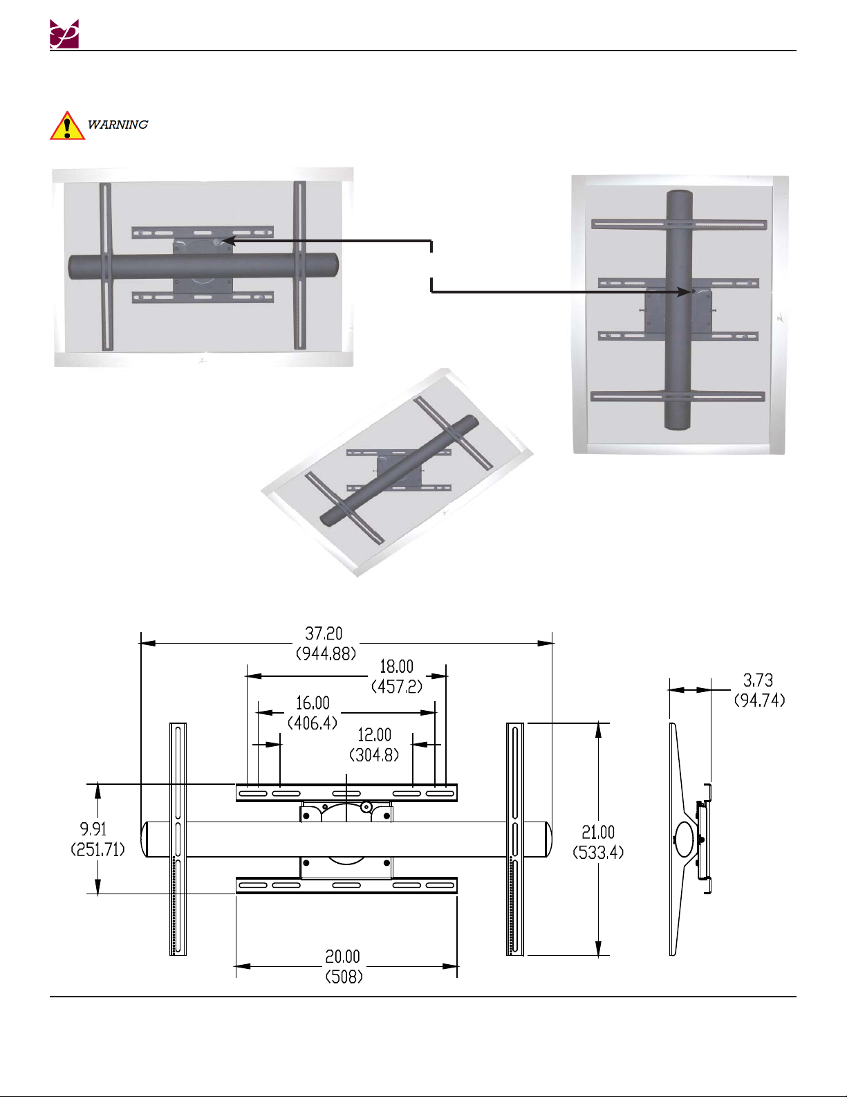
Display Orientation
The RFM will allow the user to adjust the display a full 360°.
BEFORE ROTATING THE RFM, MAKE SURE THAT THE M6 KNURL KNOB IS SECURELY FASTENED
TO THE RFM. ALSO, PLEASE MAKE SURE YOU ALLOW ENOUGH CABLE AND WIRE CLEARANCE
FOR FULL ROTATION.
M6 Knurl Knob
1. To adjust the RFM, rotate the display either
clockwise or counter-clockwise.
RFM
Technical Specifications
All measurements are in inches (mm).
2. Tighten the two Phillips
head locking screws (see Step 8,
Page 10).
Page 10 Installation Instructions
Page 11

RFM
Warranty
PREMIER MOUNTS
LIMITED LIFETIME WARRANTY
What and Who is Covered by this Limited Warranty and for How Long
Premier Mounts warrants this product to be free from defects in material and workmanship for the lifetime of
the original owner of this product. The limited warranty is valid only for the original purchaser of the product.
What Premier Mounts Will Do
At the sole option of Premier Mounts, Premier Mounts will repair or replace any product or product part that is
defective. If Premier Mounts chooses to replace a defective product or part, a replacement product or part will
be shipped to you at no charge, but you must pay any labor costs.
What is Not Covered; Limitations
PREMIER MOUNTS DISCLAIMS ANY LIABILITY FOR DAMAGE TO MOUNTS, ADAPTERS,
DISPLAYS, PROJECTORS, OTHER PROPERTY, OR PERSONAL INJURY RESULTING, IN
WHOLE OR IN PART, FROM IMPROPER INSTALLATION, MODIFICATION, USE OR MISUSE
OF ITS PRODUCTS.
PREMIER MOUNTS DISCLAIMS ALL OTHER WARRANTIES, EXPRESS OR IMPLIED, INCLUDING WARRANTIES OF MERCHANTABILITY AND FITNESS FOR A PARTICULAR PURPOSE. PREMIER MOUNTS IS NOT RESPONSIBLE FOR INCIDENTAL OR CONSEQUENTIAL
DAMAGES, INCLUDING BUT NOT LIMITED TO, INABILITY TO USE ITS PRODUCTS OR LABOR COSTS FOR REMOVING AND REPLACING DEFECTIVE PRODUCTS OR PARTS. SOME
STATES DO NOT ALLOW THE EXCLUSION OR LIMITATION OF INCIDENTAL OR CONSEQUENTIAL DAMAGES, SO THE ABOVE LIMITATION OR EXCLUSION MAY NOT APPLY TO
YOU.
What Customers Must Do for Limited Warranty Service
If you discover a problem that you think may be covered by the warranty you MUST REPORT it in writing to
the address below within thirty (30) days. Proof of purchase (an original sales receipt) from the original consumer purchaser must accompany all warranty claims. Warranty claims must also include a description of the
problem, the purchaser’s name, address, and telephone number. General inquiries can be addressed to Premier
Mounts Customer Service at 1-800-368-9700. Warranty claims will not be accepted over the phone or by fax.
Premier Mounts
Attn: Warranty Claim
3130 E. Miraloma Avenue
Anaheim, CA 92806
How State Law Applies
THIS WARRANTY GIVES YOU SPECIFIC LEGAL RIGHTS, AND YOU MAY ALSO HAVE OTHER
RIGHTS WHICH VARY FROM STATE TO STATE.
Installation Instructions Page 11
 Loading...